EP2987471A2 - Rehabilitationsschuhwerk - Google Patents
Rehabilitationsschuhwerk Download PDFInfo
- Publication number
- EP2987471A2 EP2987471A2 EP14193649.2A EP14193649A EP2987471A2 EP 2987471 A2 EP2987471 A2 EP 2987471A2 EP 14193649 A EP14193649 A EP 14193649A EP 2987471 A2 EP2987471 A2 EP 2987471A2
- Authority
- EP
- European Patent Office
- Prior art keywords
- guard pad
- fastener
- back guard
- buckle
- lateral sides
- Prior art date
- Legal status (The legal status is an assumption and is not a legal conclusion. Google has not performed a legal analysis and makes no representation as to the accuracy of the status listed.)
- Withdrawn
Links
- 239000004744 fabric Substances 0.000 claims description 7
- 230000002146 bilateral effect Effects 0.000 claims description 4
- 210000002683 foot Anatomy 0.000 description 34
- 238000011084 recovery Methods 0.000 description 10
- 210000000988 bone and bone Anatomy 0.000 description 9
- 210000004872 soft tissue Anatomy 0.000 description 8
- 210000003423 ankle Anatomy 0.000 description 5
- 238000000034 method Methods 0.000 description 3
- 230000002708 enhancing effect Effects 0.000 description 2
- 239000011505 plaster Substances 0.000 description 2
- 208000010392 Bone Fractures Diseases 0.000 description 1
- 208000034656 Contusions Diseases 0.000 description 1
- 206010017076 Fracture Diseases 0.000 description 1
- 206010024453 Ligament sprain Diseases 0.000 description 1
- 208000010040 Sprains and Strains Diseases 0.000 description 1
- 208000027418 Wounds and injury Diseases 0.000 description 1
- 230000009519 contusion Effects 0.000 description 1
- 230000006378 damage Effects 0.000 description 1
- 208000014674 injury Diseases 0.000 description 1
- 238000001356 surgical procedure Methods 0.000 description 1
Images




Classifications
-
- A—HUMAN NECESSITIES
- A61—MEDICAL OR VETERINARY SCIENCE; HYGIENE
- A61F—FILTERS IMPLANTABLE INTO BLOOD VESSELS; PROSTHESES; DEVICES PROVIDING PATENCY TO, OR PREVENTING COLLAPSING OF, TUBULAR STRUCTURES OF THE BODY, e.g. STENTS; ORTHOPAEDIC, NURSING OR CONTRACEPTIVE DEVICES; FOMENTATION; TREATMENT OR PROTECTION OF EYES OR EARS; BANDAGES, DRESSINGS OR ABSORBENT PADS; FIRST-AID KITS
- A61F5/00—Orthopaedic methods or devices for non-surgical treatment of bones or joints; Nursing devices ; Anti-rape devices
- A61F5/01—Orthopaedic devices, e.g. long-term immobilising or pressure directing devices for treating broken or deformed bones such as splints, casts or braces
- A61F5/0195—Shoe-like orthopaedic devices for protecting the feet against injuries after operations
-
- A—HUMAN NECESSITIES
- A61—MEDICAL OR VETERINARY SCIENCE; HYGIENE
- A61F—FILTERS IMPLANTABLE INTO BLOOD VESSELS; PROSTHESES; DEVICES PROVIDING PATENCY TO, OR PREVENTING COLLAPSING OF, TUBULAR STRUCTURES OF THE BODY, e.g. STENTS; ORTHOPAEDIC, NURSING OR CONTRACEPTIVE DEVICES; FOMENTATION; TREATMENT OR PROTECTION OF EYES OR EARS; BANDAGES, DRESSINGS OR ABSORBENT PADS; FIRST-AID KITS
- A61F5/00—Orthopaedic methods or devices for non-surgical treatment of bones or joints; Nursing devices ; Anti-rape devices
- A61F5/01—Orthopaedic devices, e.g. long-term immobilising or pressure directing devices for treating broken or deformed bones such as splints, casts or braces
- A61F5/0102—Orthopaedic devices, e.g. long-term immobilising or pressure directing devices for treating broken or deformed bones such as splints, casts or braces specially adapted for correcting deformities of the limbs or for supporting them; Ortheses, e.g. with articulations
- A61F5/0104—Orthopaedic devices, e.g. long-term immobilising or pressure directing devices for treating broken or deformed bones such as splints, casts or braces specially adapted for correcting deformities of the limbs or for supporting them; Ortheses, e.g. with articulations without articulation
- A61F5/0111—Orthopaedic devices, e.g. long-term immobilising or pressure directing devices for treating broken or deformed bones such as splints, casts or braces specially adapted for correcting deformities of the limbs or for supporting them; Ortheses, e.g. with articulations without articulation for the feet or ankles
-
- A—HUMAN NECESSITIES
- A61—MEDICAL OR VETERINARY SCIENCE; HYGIENE
- A61F—FILTERS IMPLANTABLE INTO BLOOD VESSELS; PROSTHESES; DEVICES PROVIDING PATENCY TO, OR PREVENTING COLLAPSING OF, TUBULAR STRUCTURES OF THE BODY, e.g. STENTS; ORTHOPAEDIC, NURSING OR CONTRACEPTIVE DEVICES; FOMENTATION; TREATMENT OR PROTECTION OF EYES OR EARS; BANDAGES, DRESSINGS OR ABSORBENT PADS; FIRST-AID KITS
- A61F5/00—Orthopaedic methods or devices for non-surgical treatment of bones or joints; Nursing devices ; Anti-rape devices
- A61F5/01—Orthopaedic devices, e.g. long-term immobilising or pressure directing devices for treating broken or deformed bones such as splints, casts or braces
- A61F5/0102—Orthopaedic devices, e.g. long-term immobilising or pressure directing devices for treating broken or deformed bones such as splints, casts or braces specially adapted for correcting deformities of the limbs or for supporting them; Ortheses, e.g. with articulations
- A61F5/0127—Orthopaedic devices, e.g. long-term immobilising or pressure directing devices for treating broken or deformed bones such as splints, casts or braces specially adapted for correcting deformities of the limbs or for supporting them; Ortheses, e.g. with articulations for the feet
Definitions
- the present invention relates to a rehabilitation footwear, especially to a rehabilitation footwear that can fix bones of an injured foot and has adjustable functions according to different stages of recovery and rehabilitation.
- An injured person's foot after surgery, fracture, sprain or contusion needs to be fixed with plaster to fix soft tissues as well as bones in a right position.
- the purpose of using plaster is to prevent the soft tissues and the bones from shifting and causing a secondary injury and to enhance rehabilitation of the foot.
- a rehabilitation footwear is available on the market.
- Conventional rehabilitation footwear includes an ankle rehabilitation footwear and a rehabilitation footwear.
- the ankle rehabilitation footwear is used for protecting a sole and an ankle of the foot.
- the high leg rehabilitation footwear is used for protecting a shank of the leg.
- the ankle rehabilitation footwear is restricted to rehabilitate an injured region of the sole and ankle of the foot.
- the high leg rehabilitation footwear is designed with an adjustable or nonadjustable height.
- the high leg rehabilitation footwear with adjustable height can be adjusted according to the injured region of the foot.
- the high leg rehabilitation footwear with adjustable height lacks a design for full cover protection and for different recovery stages of the foot.
- the conventional rehabilitation footwear lacks the adjustable function based on the recovery stages of the foot to enhance the recovery rate of the soft tissues as well as the bones of the injured person.
- the present invention provides a rehabilitation footwear to mitigate or obviate the aforementioned problems.
- the main objective of the invention is to provide a rehabilitation footwear with an adjustable function according to the recovery stages of an injured person's foot.
- the rehabilitation footwear in accordance with the present invention has a shoe body, multiple fasteners, a back guard pad, a front guard pad, two supporting frames and an encircling band.
- the shoe body comprises multiple buckles and two concave grooves.
- Each of the multiple fasteners comprises a buckle ring and a band ring.
- the buckle ring is fastened with one of the multiple buckles of the shoe body.
- the back guard pad comprises a lower back guard pad, a middle back guard pad, and an upper back guard pad.
- the lower back guard pad comprises two protrusion parts, multiple holes and multiple perforations.
- the two protrusion parts of the back guard pad are interlocked with the two concave grooves of the shoe body.
- the middle back guard pad comprises multiple buckles and multiple clasps.
- the multiple buckles of the middle back guard pass through the multiple holes of the lower back guard pad and are fastened with the buckle rings of the multiple fasteners.
- the multiple clasps of the middle back guard are clasped with the perforations of the lower back guard pad.
- the upper back guard pad comprises multiple buckles and multiple clasps.
- the multiple buckles of the upper back guard pad pass through the multiple holes of the lower back guard pad and are fastened with the buckle rings of the multiple fasteners.
- the multiple clasps of the upper back guard pad are clasped with the multiple perforations of the lower back guard pad.
- the front guard pad comprises a lower front guard pad, a middle front guard pad, and an upper front guard pad.
- the lower front guard pad comprises a clasp.
- the middle front guard pad comprises a perforation clasped with the clasp of the lower front guard pad.
- the upper front guard pad comprises a perforation clasped with the clasp of the lower front guard pad.
- Each of the two supporting frames comprises a protrusion part and multiple band rings.
- the protrusion part of each of the two supporting frames is interlocked with each of the two concave grooves of the shoe body.
- the encircling band passes through the multiple band rings of the two supporting frames that are positioned correspondingly to each other.
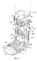
- a full-cover rehabilitation footwear is built up by combination of the shoe body, the lower back guard pad, the upper back guard pad, the lower front guard pad and the upper front guard pad, and fixed with the injured person's foot by the encircling band passing through the band rings of the multiple fasteners corresponding to each other.
- a supporting-type rehabilitation footwear is built up by combination of the shoe body, the lower back guard pad, the middle back guard pad, the lower front guard pad and the middle front guard pad, and fixed with the injured person's foot by the encircling band passing through the band rings of the multiple fasteners corresponding to each other.
- a frame-type rehabilitation footwear is built up by combination of the shoe body and the two supporting frames, and fixed with the injured person's foot by the encircling band passing through the multiple band rings of the two supporting frames corresponding to each other.
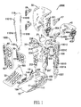
- a first embodiment of a rehabilitation footwear in accordance with the present invention comprises a shoe body 10, a back guard pad 1000, a front guard pad 2000, a first fastener 11, a second fastener 12, a third fastener 13, a fourth fastener 14, a fifth fastener 15, a sixth fastener 16, a seventh fastener 17, an eighth fastener 18, a first fill A and a second fill B.
- the shoe body 10 comprises two lateral sides and a back end respectively corresponding to bilateral sides and a heel of a human's foot.
- the two lateral sides and the back end of the shoe body 10 form a capacity space for accommodating the human's foot.
- the two lateral sides comprise a first buckle 111, a second buckle 122, a third buckle 133, and a fourth buckle 144.
- the back end of the shoe body 10 comprises a first concave groove 155 and a second concave groove 166.
- the back guard pad 1000 comprises a lower back guard pad 20 and an upper back guard pad 30.
- the lower back guard pad 20 comprises three lateral sides connected with each other at nearly right angle, allowing to be formed a lower capacity space for accommodating a back of a human's shank.
- the lower capacity space comprises a lower end and an upper end.
- Two of the lateral sides of the lower back guard pad 20 opposite each other and corresponding to the lower end of the lower capacity space extend and form a first protrusion part 201 and a second protrusion part 202.
- the first protrusion part 201 and the second protrusion part 202 are respectively interlocked with the first concave groove 155 and the second concave groove 166 of the shoe body10, allowing the back guard pad 1000 to be fixed with the shoe body 10.
- the two opposite lateral sides of the lower back guard pad 20 comprise a first hole 203 and a second hole 204.
- the two lateral sides of the lower back guard pad 20 opposite each other and corresponding to the upper end of the capacity space extend outwards and form a small capacity space.
- the small capacity space corresponding to the two lateral sides of the lower back guard pad 20 opposite each other forms a third hole 205, a fourth hole 206, a fifth hole 207, a sixth hole 208, a first perforation 209, a second perforation 210, a third perforation 211 and a fourth perforation 212.
- the upper back guard pad 30 comprises three lateral sides connected with each other at nearly right angle, allowing to be formed an upper capacity space for accommodating the back of the human's shank.
- the upper capacity space comprises a lower end and an upper end.
- Two of the lateral sides of the upper back guard pad 30 opposite each other and corresponding to the upper end of the upper capacity space comprise a first upper buckle 301 and a second upper buckle.
- the two lateral sides of the upper back guard pad 30 opposite each other and corresponding to the lower end of the upper capacity space comprise a third upper buckle 303 and a fourth upper buckle.
- the third upper buckle 303 and the fourth upper buckle respectively pass through the first hole 203 and the second hole 204 of the lower back guard pad 20.
- the two lateral sides of the upper back guard pad 30 opposite each other and corresponding to the lower end of the upper capacity space extend outwards and form protrusion structures.
- One of the protrusion structures is a protrusion structure 30A.
- the protrusion structure 30A comprises a surrounding a recess, and the first fill A is placed in the recess of the protrusion structure 30A.
- the protrusion structure 30A is fitted into the small capacity space of the lower back guard pad 20.
- the other one of the protrusion structures is identical to the protrusion structure 30A and positioned oppositely to the protrusion structure 30A of the upper back guard pad 30.
- the other one of the protrusion structures comprises a surrounding wall having a recess, and the second fill B is placed in the recess of the other one of the protrusion structures.
- the protrusion structure 30A and the second fill B are fit into the small capacity space of the two opposite lateral sides of the lower back guard pad 20.
- the first fill A comprises a first bump A1 and a second bump A2.
- the second fill B comprises a third bump B1 and a fourth bump.
- the first bump A1 passes through the third hole 205 of the lower back guard pad 20, and the second bump A2 passes through the fourth hole 206 of the lower back guard pad 20.
- the third bump B1 passes through the fifth hole 207 of the lower back guard pad 20, and the fourth bump passes through the sixth hole 208 of the lower back guard pad 20.
- Two lateral sides of the surrounding wall of the protrusion structure 30A comprise a first clasp 305 and a second clasp 306 formed toward outside of the recess.
- the first clasp 305 passes through and is clasped with the first perforation 209 of the lower back guard pad 20.
- the second clasp 306 passes through and is clasped with the second perforation 210 of the lower back guard pad 20, allowing the lower back guard pad 20 to be fixed with the upper back guard pad 30.
- the first fastener 11, the second fastener 12, the third fastener 13, the fourth fastener 14, the fifth fastener 15, the sixth fastener 16, the seventh fastener 17 and the eighth fastener 18 each comprises two ends.
- One end of each of the first fastener 11, the second fastener 12, the third fastener 13, the fourth fastener 14, the fifth fastener 15, the sixth fastener 16, the seventh fastener 17 and the eighth fastener 18 comprises a buckle ring respectively corresponding to the first buckle 111, the second buckle 122, the third buckle 133, the fourth buckle 144, and the first upper buckle 301, the second upper buckle, the third upper buckle 303 and the fourth upper buckle of the upper back guard pad 30.
- each of the first fastener 11, the second fastener 12, the third fastener 13, the fourth fastener 14, the fifth fastener 15, the sixth fastener 16, the seventh fastener 17 and the eighth fastener 18 comprises a band ring, allowing an encircling band 80 to be passed through.
- the encircling band 80 comprises a fabric hook and loop fastener.
- the front guard pad 2000 comprises a lower front guard pad 50 and an upper front guard pad 60.
- the lower front guard pad 50 comprises a front end and a back end.
- the back end of the lower front guard pad 50 comprises a clasp 501.
- the upper front guard pad 60 comprises a front end.
- the front end of the upper front guard pad 60 comprises a clasp 601.
- a method for using the first embodiment comprises:
- the first embodiment allows soft tissues as well as bones of the injured person's foot to be protected by fixing in a full-cover rehabilitation footwear, and avoids shifting of the soft tissues and bones to enhance recovery.
- a second embodiment of the rehabilitation footwear in accordance with the present invention comprises a shoe body 10, a back guard pad 1000, a front guard pad 2000, a first fastener 11, a second fastener 12, a third fastener 13, a fourth fastener 14, a fifth fastener 15, a sixth fastener 16, a first fill A and a second fill B.
- the shoe body 10 comprises two lateral sides and a back end corresponding to bilateral sides and a heel of a human's foot, respectively.
- the two lateral sides and the back end of the shoe body 10 form a capacity space for accommodating the human's foot.
- the two lateral sides comprise a first buckle 111, a second buckle 122, a third buckle 133, and a fourth buckle 144.
- the back end of the shoe body 10 comprises a first concave groove 155 and a second concave groove 166.
- the back guard pad 1000 comprises a lower back guard pad 20 and a middle back guard pad 40.
- the lower back guard pad 20 comprises three lateral sides connected with each other at nearly right angle, allowing to be formed a lower capacity space for accommodating the back of the human's shank.
- the lower capacity space comprises a lower end and an upper end.
- Two of the lateral sides of the lower back guard pad 20 opposite each other and corresponding to the lower end of the lower capacity space extend and form a first protrusion part 201 and a second protrusion part 202.
- the first protrusion part 201 and the second protrusion part 202 are respectively interlocked with the first concave groove 155 and the second concave groove 166 of the shoe body10, allowing the back guard pad 1000 to be fixed with the shoe body 10.
- the two opposite lateral sides of the lower back guard pad 20 comprise a first hole 203 and a second hole 204.
- the two lateral sides of the lower back guard pad 20 opposite with each other and corresponding to the upper end of the capacity space extend outwards and form a second small capacity space.
- the second small capacity space corresponding to the two opposite lateral sides of the lower back guard pad 20 forms a third hole 205, a fourth hole 206, a fifth hole 207, a sixth hole 208, a first perforation 209, a second perforation 210, a third perforation 211 and a fourth perforation 212.
- the middle back guard pad 40 is smaller than the upper back guard pad 30 and comprises three lateral sides connected with each other at nearly right angle, allowing to be formed a middle capacity space for accommodating the back of the human's shank.
- the middle capacity space comprises a lower end and an upper end.
- the two lateral sides of the middle back guard pad 40 opposite each other and corresponding to the lower end of the middle capacity space comprise a first middle buckle 401 and a second middle buckle.
- the first middle buckle 401 and the second middle buckle pass through the first hole 203 and the second hole 204 of the lower back guard pad 20, respectively.
- Two of the lateral sides of the middle back guard pad 40 opposite each other and corresponding to the upper end of the middle capacity space extend outwards and form protrusion structures.
- One of the protrusion structures is a second protrusion structure 40A.
- the second protrusion structure 40A comprises a surrounding wall having a second recess, and the first fill A is placed in the second recess of the second protrusion structure 40A.
- the second protrusion structure 40A is fitted into the small capacity space of the lower back guard pad 20.
- the other one of the protrusion structures is identical to the second protrusion structure 40A and positioned oppositely to the second protrusion structure 40A of the middle back guard pad 40.
- the other one of the protrusion structures comprises a surrounding wall having a recess formed threin, and the second fill B is placed in the recess of the other one of the protrusion structures.
- the second protrusion structure 40A and the second fill B are fit into the small capacity space of the two opposite lateral sides of the lower back guard pad 20.
- the first fill A comprises a first bump A1 and a second bump A2.
- the second fill B comprises a third bump B1 and a fourth bump.
- the first bump A1 passes through the third hole 205 of the lower back guard pad 20, and the second bump A2 passes through the fourth hole 206 of the lower back guard pad 20.
- the third bump B1 passes through the fifth hole 207 of the lower back guard pad 20, and the fourth bump passes through the sixth hole 208 of the lower back guard pad 20.
- Two lateral sides of the surrounding wall of the second protrusion structure 40A comprise a third clasp 403 and a fourth clasp 404 formed toward outside of the recess.
- the third clasp 403 passes through and is clasped with the first perforation 209 of the lower back guard pad 20.
- the fourth clasp 404 passes through and is clasped with the second perforation 210 of the lower back guard pad 20, allowing the lower back guard pad 20 to be fixed with the middle back guard pad 40.
- the first fastener 11, the second fastener 12, the third fastener 13, the fourth fastener 14, the fifth fastener 15, the sixth fastener 16, the seventh fastener 17 and the eighth fastener 18 each comprise two ends.
- One end of each of the first fastener 11, the second fastener 12, the third fastener 13, the fourth fastener 14, the fifth fastener 15, the sixth fastener 16, the seventh fastener 17 and the eighth fastener 18 comprises a buckle ring corresponding respectively to the first buckle 111, the second buckle 122, the third buckle 133, the fourth buckle 144, and the first middle buckle 401, the second middle buckle of the middle back guard pad 40.
- each of the first fastener 11, the second fastener 12, the third fastener 13, the fourth fastener 14, the fifth fastener 15, and the sixth fastener 16 comprises a band ring, allowing an encircling band 80 to be passed through.
- the encircling band 80 comprises a fabric hook and loop fastener.
- the front guard pad 2000 comprises a lower front guard pad 50 and a middle front guard pad 70.
- the lower front guard pad 50 comprises a front end and a back end.
- the back end of the lower front guard pad 50 comprises a clasp 501.
- the middle front guard pad 70 comprises a front end.
- the front end of the middle front guard pad 70 comprises a clasp 701.
- the rehabilitation footwear of the fist embodiment can be replaced by the second embodiment.
- the rehabilitation footwear of the second embodiment allows the soft tissues as well as bones of the injured person's foot to be protected by fixing in a supporting-type rehabilitation footwear further for enhancing the rate of recovery.
- a third embodiment of the rehabilitation footwear in accordance with the present invention comprises a shoe body 10, frames, a first fastener 11, a second fastener 12, a third fastener 13, a fourth fastener 14, a fifth fastener 15 and a sixth fastener 16.
- the shoe body 10 comprises two lateral sides and a back end corresponding to bilateral sides and a heel of a human's foot, respectively.
- the two lateral sides and the back end of the shoe body 10 form a capacity space for accommodating the human's foot.
- the two lateral sides comprise a first buckle 111, a second buckle 122, a third buckle 133, and a fourth buckle 144.
- the back end of the shoe body 10 comprises a first concave groove 155 and a second concave groove 166.
- the frames comprise a first supporting frame 100 and a second supporting frame 110.
- Each of the first supporting frame 100 and the second supporting frame 110 comprises a lower end, a middle end, an upper end and two lateral sides.
- the lower ends of the first supporting frame 100 and the second supporting frame 110 extend and respectively form a first protrusion part 1001 and a second protrusion part 1101.
- the first protrusion part 1001 of the first supporting frame 100 and the second protrusion part 1101 of the second supporting frame 110 are respectively interlocked with the first concave groove 155 and the second concave groove 166 of the shoe body10.
- the two lateral sides of the middle end of the first supporting frame 100 comprise a first band ring 1001A and a second band ring 1001B; the two lateral sides of the upper end of the first supporting frame 100 comprise a third band ring 1001C and a fourth band ring 1001D.
- the two lateral sides of the middle end of the second supporting frame 110 comprise a fifth band ring 1101A and a sixth band ring 1101B; the two lateral sides of the upper end of the second supporting frame 110 comprises a seventh band ring 1101C and an eighth band ring 1101D.
- the first fastener 11, the second fastener 12, the third fastener 13, the fourth fastener 14, the fifth fastener 15 and the sixth fastener 16 each comprise two ends.
- One end of each of the first fastener 11, the second fastener 12, the third fastener 13, the fourth fastener 14, the fifth fastener 15 and the sixth fastener 16 comprises a buckle ring corresponding respectively to the first buckle 111, the second buckle 122, the third buckle 133, the fourth buckle 144, allowing an encircling band 80 to be passed through.
- the encircling band 80 comprises a fabric hook and loop fastener.
- a method for using the first embodiment comprises:
- the rehabilitation footwear of the second embodiment can be replaced by the third embodiment.
- the rehabilitation footwear of the second embodiment allows the soft tissues as well as bones of the injured person's foot to be protected by fixing in a frame-type rehabilitation footwear further for enhancing the rate of recovery.
Landscapes
- Health & Medical Sciences (AREA)
- Nursing (AREA)
- Orthopedic Medicine & Surgery (AREA)
- Engineering & Computer Science (AREA)
- Biomedical Technology (AREA)
- Heart & Thoracic Surgery (AREA)
- Vascular Medicine (AREA)
- Life Sciences & Earth Sciences (AREA)
- Animal Behavior & Ethology (AREA)
- General Health & Medical Sciences (AREA)
- Public Health (AREA)
- Veterinary Medicine (AREA)
- Footwear And Its Accessory, Manufacturing Method And Apparatuses (AREA)
Applications Claiming Priority (1)
| Application Number | Priority Date | Filing Date | Title |
|---|---|---|---|
| TW103128358A TWI538666B (zh) | 2014-08-18 | 2014-08-18 | Rehabilitation shoes |
Publications (2)
| Publication Number | Publication Date |
|---|---|
| EP2987471A2 true EP2987471A2 (de) | 2016-02-24 |
| EP2987471A3 EP2987471A3 (de) | 2016-04-20 |
Family
ID=51951627
Family Applications (1)
| Application Number | Title | Priority Date | Filing Date |
|---|---|---|---|
| EP14193649.2A Withdrawn EP2987471A3 (de) | 2014-08-18 | 2014-11-18 | Rehabilitationsschuhwerk |
Country Status (4)
| Country | Link |
|---|---|
| US (1) | US20160045354A1 (de) |
| EP (1) | EP2987471A3 (de) |
| CA (1) | CA2900717A1 (de) |
| TW (1) | TWI538666B (de) |
Families Citing this family (9)
| Publication number | Priority date | Publication date | Assignee | Title |
|---|---|---|---|---|
| EP3431056B1 (de) * | 2016-03-15 | 2021-12-01 | Kim, Choonghwan | Beinschutz |
| EP3474697B1 (de) | 2016-06-23 | 2023-03-15 | Darco International, Inc. | Medizinischer schuh mit multidichte-umspritzen |
| EP3474696B1 (de) * | 2016-06-23 | 2020-11-18 | Darco International Inc. | Medizinischer schuh mit mehreren aussensohlenprojektionen |
| USD861180S1 (en) | 2017-10-27 | 2019-09-24 | Foot Defender, LLC | Cam walker |
| CN108354701B (zh) * | 2018-03-29 | 2023-12-08 | 北京大学第三医院 | 一种跟腱靴支具及其制作方法 |
| DE102018110900A1 (de) * | 2018-05-07 | 2019-11-07 | Condor Medtec Gmbh | Extensions-Fußmanschette |
| US11253383B2 (en) | 2018-09-20 | 2022-02-22 | Foot Defender Llc | CAM walker with removable collar |
| TWD203324S (zh) | 2019-07-17 | 2020-03-11 | 豐利國際有限公司 | 復健鞋的部分 |
| US12611324B2 (en) | 2022-09-02 | 2026-04-28 | Ossur Iceland Ehf | Orthopedic walker |
Family Cites Families (9)
| Publication number | Priority date | Publication date | Assignee | Title |
|---|---|---|---|---|
| US7597674B2 (en) * | 2002-07-23 | 2009-10-06 | össur hf | Versatile orthopaedic leg mounted walker |
| US7303538B2 (en) * | 2002-07-23 | 2007-12-04 | Ossur Hf | Versatile orthopaedic leg mounted walkers |
| US7524295B1 (en) * | 2007-06-25 | 2009-04-28 | Ultra Athlete Llc | Convertible ankle brace |
| CN101827568A (zh) * | 2007-10-15 | 2010-09-08 | 奥索集团公司 | 具有患者顺从性系统的整形外科装置 |
| US7666157B2 (en) * | 2007-10-31 | 2010-02-23 | Jeff Win | Surgical protective tool positioning apparatus |
| US20090306565A1 (en) * | 2008-06-05 | 2009-12-10 | Shu-Chen Chan | Rehabilitation walking boot |
| US9180038B2 (en) * | 2010-08-05 | 2015-11-10 | Ossur Hf | Walker having height adjustment and method for doing the same |
| US10449078B2 (en) * | 2013-03-15 | 2019-10-22 | Ovation Medical | Modular system for an orthopedic walking boot |
| US9839550B2 (en) * | 2013-09-25 | 2017-12-12 | Ossur Hf | Orthopedic device |
-
2014
- 2014-08-18 TW TW103128358A patent/TWI538666B/zh not_active IP Right Cessation
- 2014-11-17 US US14/542,836 patent/US20160045354A1/en not_active Abandoned
- 2014-11-18 EP EP14193649.2A patent/EP2987471A3/de not_active Withdrawn
-
2015
- 2015-08-18 CA CA2900717A patent/CA2900717A1/en not_active Abandoned
Non-Patent Citations (1)
| Title |
|---|
| None |
Also Published As
| Publication number | Publication date |
|---|---|
| TW201607523A (zh) | 2016-03-01 |
| CA2900717A1 (en) | 2016-02-18 |
| TWI538666B (zh) | 2016-06-21 |
| EP2987471A3 (de) | 2016-04-20 |
| US20160045354A1 (en) | 2016-02-18 |
Similar Documents
| Publication | Publication Date | Title |
|---|---|---|
| EP2987471A2 (de) | Rehabilitationsschuhwerk | |
| US7125392B2 (en) | Ankle-foot orthotic device and method | |
| US4323058A (en) | Ankle brace | |
| US7905850B2 (en) | Device and method for combining an athletic shoe and conventional ankle brace to limit active ankle inversion | |
| US10383404B2 (en) | Lace-tongue attachment for ankle stabilizing device | |
| KR200480494Y1 (ko) | 발가락 교정기 | |
| US20100050473A1 (en) | Exercise sneaker having a plurality of attachment points along an outer peripheral thereof for attaching an elastic band to perform exercise movements | |
| US9603736B1 (en) | Enhanced forefoot protection for orthopedic rehabilitation devices | |
| JP2015071039A (ja) | 靴 | |
| US11607332B2 (en) | Relief orthosis | |
| US20170367865A1 (en) | Ankle reinforcing device | |
| US1562294A (en) | Leg and foot developer | |
| US7267656B2 (en) | Ankle brace | |
| US20170172248A1 (en) | Arch Support | |
| CN110913807B (zh) | 用于鞋类的速率相关系统 | |
| KR102462175B1 (ko) | 발가락 스트레칭기 | |
| CA2908912A1 (en) | Shoe interfaced ankle support apparatus | |
| JP6346874B2 (ja) | 靴 | |
| US20070039207A1 (en) | Pant protector | |
| CN105361990A (zh) | 复健鞋 | |
| CN204033560U (zh) | 复健鞋 | |
| US20240091040A1 (en) | Orthotic ankle support device | |
| EP2929795A1 (de) | Einspannvorrichtung für Schuhwerk und Schuhwerk mit solcher Einspannvorrichtung | |
| KR200391874Y1 (ko) | 탭댄스용 덧신 | |
| JP2015054186A (ja) | 締結ベルト付きリハビリ靴 |
Legal Events
| Date | Code | Title | Description |
|---|---|---|---|
| PUAI | Public reference made under article 153(3) epc to a published international application that has entered the european phase |
Free format text: ORIGINAL CODE: 0009012 |
|
| AK | Designated contracting states |
Kind code of ref document: A2 Designated state(s): AL AT BE BG CH CY CZ DE DK EE ES FI FR GB GR HR HU IE IS IT LI LT LU LV MC MK MT NL NO PL PT RO RS SE SI SK SM TR |
|
| AX | Request for extension of the european patent |
Extension state: BA ME |
|
| PUAL | Search report despatched |
Free format text: ORIGINAL CODE: 0009013 |
|
| AK | Designated contracting states |
Kind code of ref document: A3 Designated state(s): AL AT BE BG CH CY CZ DE DK EE ES FI FR GB GR HR HU IE IS IT LI LT LU LV MC MK MT NL NO PL PT RO RS SE SI SK SM TR |
|
| AX | Request for extension of the european patent |
Extension state: BA ME |
|
| RIC1 | Information provided on ipc code assigned before grant |
Ipc: A61F 5/01 20060101AFI20160314BHEP |
|
| STAA | Information on the status of an ep patent application or granted ep patent |
Free format text: STATUS: THE APPLICATION HAS BEEN PUBLISHED |
|
| STAA | Information on the status of an ep patent application or granted ep patent |
Free format text: STATUS: THE APPLICATION IS DEEMED TO BE WITHDRAWN |
|
| 18D | Application deemed to be withdrawn |
Effective date: 20161021 |