EP2987914A1 - Stossdämpfende vorrichtung für leitplankenende - Google Patents
Stossdämpfende vorrichtung für leitplankenende Download PDFInfo
- Publication number
- EP2987914A1 EP2987914A1 EP14786109.0A EP14786109A EP2987914A1 EP 2987914 A1 EP2987914 A1 EP 2987914A1 EP 14786109 A EP14786109 A EP 14786109A EP 2987914 A1 EP2987914 A1 EP 2987914A1
- Authority
- EP
- European Patent Office
- Prior art keywords
- guardrail
- opened
- connection flange
- column part
- connection
- Prior art date
- Legal status (The legal status is an assumption and is not a legal conclusion. Google has not performed a legal analysis and makes no representation as to the accuracy of the status listed.)
- Withdrawn
Links
- 230000035939 shock Effects 0.000 title claims abstract description 69
- 125000006850 spacer group Chemical group 0.000 claims abstract description 56
- 230000000903 blocking effect Effects 0.000 claims description 10
- 230000000149 penetrating effect Effects 0.000 abstract description 3
- 239000000470 constituent Substances 0.000 description 5
- 230000006378 damage Effects 0.000 description 4
- 229910000831 Steel Inorganic materials 0.000 description 3
- 230000000712 assembly Effects 0.000 description 3
- 238000000429 assembly Methods 0.000 description 3
- 238000000034 method Methods 0.000 description 3
- 230000002265 prevention Effects 0.000 description 3
- 239000010959 steel Substances 0.000 description 3
- 238000010521 absorption reaction Methods 0.000 description 2
- 230000000694 effects Effects 0.000 description 2
- 238000009434 installation Methods 0.000 description 2
- 230000002787 reinforcement Effects 0.000 description 2
- 239000002023 wood Substances 0.000 description 2
- 102100026827 Protein associated with UVRAG as autophagy enhancer Human genes 0.000 description 1
- 101710102978 Protein associated with UVRAG as autophagy enhancer Proteins 0.000 description 1
- 208000027418 Wounds and injury Diseases 0.000 description 1
- 238000004873 anchoring Methods 0.000 description 1
- 238000010276 construction Methods 0.000 description 1
- 208000014674 injury Diseases 0.000 description 1
- 239000000463 material Substances 0.000 description 1
- 238000012986 modification Methods 0.000 description 1
- 230000004048 modification Effects 0.000 description 1
- 230000002093 peripheral effect Effects 0.000 description 1
- 230000003068 static effect Effects 0.000 description 1
- 238000003466 welding Methods 0.000 description 1
Images







Classifications
-
- E—FIXED CONSTRUCTIONS
- E01—CONSTRUCTION OF ROADS, RAILWAYS, OR BRIDGES
- E01F—ADDITIONAL WORK, SUCH AS EQUIPPING ROADS OR THE CONSTRUCTION OF PLATFORMS, HELICOPTER LANDING STAGES, SIGNS, SNOW FENCES, OR THE LIKE
- E01F15/00—Safety arrangements for slowing, redirecting or stopping errant vehicles, e.g. guard posts or bollards; Arrangements for reducing damage to roadside structures due to vehicular impact
- E01F15/14—Safety arrangements for slowing, redirecting or stopping errant vehicles, e.g. guard posts or bollards; Arrangements for reducing damage to roadside structures due to vehicular impact specially adapted for local protection, e.g. for bridge piers, for traffic islands
- E01F15/143—Protecting devices located at the ends of barriers
-
- E—FIXED CONSTRUCTIONS
- E01—CONSTRUCTION OF ROADS, RAILWAYS, OR BRIDGES
- E01F—ADDITIONAL WORK, SUCH AS EQUIPPING ROADS OR THE CONSTRUCTION OF PLATFORMS, HELICOPTER LANDING STAGES, SIGNS, SNOW FENCES, OR THE LIKE
- E01F15/00—Safety arrangements for slowing, redirecting or stopping errant vehicles, e.g. guard posts or bollards; Arrangements for reducing damage to roadside structures due to vehicular impact
- E01F15/14—Safety arrangements for slowing, redirecting or stopping errant vehicles, e.g. guard posts or bollards; Arrangements for reducing damage to roadside structures due to vehicular impact specially adapted for local protection, e.g. for bridge piers, for traffic islands
Definitions
- the present invention relates to a guardrail end shock absorbing device, and more particularly, to a guardrail end shock absorbing device that is adapted to absorb shock when a vehicle runs into an end of a guardrail.
- a guardrail assembly is an installation that is referred to as a protection fence and is installed along a centerline or a perimeter of a road so as to prevent a vehicle from deviating from its lane or moving out from the road.
- a protection fence is installed along a centerline or a perimeter of a road so as to prevent a vehicle from deviating from its lane or moving out from the road.
- fatal accidents that have been caused by vehicles that ran into guardrail assemblies occupy about 10% of the fatal accidents that have occurred due to vehicles that ran into, for example, street trees, telephone poles, and protection fences that are installed along perimeters of roads.
- side collision accidents occupy 75% and end collision accidents occupy 25%.
- guardrail assemblies installed for the purpose of vehicle safety which causes damage to vehicles and even the loss of lives.
- the end of the guardrail assembly may penetrate the vehicle and may directly inflict injury on a passenger.
- a measure to minimize vehicle damage or life damage when a vehicle runs into an end of a guardrail assembly is required.
- a number of techniques to absorb impact when a vehicle runs into an end of a guardrail assembly by employing a shock absorbing configuration in the guardrail assembly have been proposed.
- the techniques are adapted to absorb shock when a vehicle collision is caused.
- Korean Patent No. 10-912464 discloses a guardrail that includes shock-absorbing zone, in which a plurality of longitudinal slots are formed in the middle of the body of the guardrail so as to absorb shock energy when a vehicle runs into a side end of the guardrail in a longitudinal direction.
- the guardrail includes a support column that is fixed by accommodating therein first and second fitting members that are fixed by a blockout and are configured to be vertically separable from each other.
- the support column includes an upper column part and a lower column part that are formed of a pipe with a circular cross-section, and reinforcement against side collision is provided using a connection cable.
- a method of absorbing shock in the configuration as described above is as follows: since the guardrail includes a plurality of longitudinal slots, when the guardrail is subjected to a head-on collision, the guardrail buckles to disperse the collision energy. That is, the plastic deformation of the guardrail is used.
- the flanges for connecting the upper column part and the lower column part are connected with a dovetail structure.
- the upper column part and the lower column part are configured to be separated in a head-on collision direction so as to be broken away, but not to be separated in a side collision direction.
- problems may occurs in that the dovetail structures of the flanges are difficult to form and thus costs a lot. Since the guardrail is easily bent at the time of side collision due to the longitudinal slots formed in the guardrail, the maximum collision deformation distance may exceed a prescribed value.
- a support column is configured not to be vertically separated, and a connection cable is provided in a configuration that allows a guardrail to connect support columns so as to provide reinforcement against side collision.
- a rectangular wood or a steel I-beam is used for the support column.
- the U.S. Patent uses the fact that the rectangular wood or the steel I-beam has a section coefficient of material mechanics that exhibits a strength in the side collision direction that is five or more times a strength in the head-on collision direction so that when a head-on collision occurs, the support column is fractured or bent to be broken away and when a side collision occurs, the support column is not broken away since the strength is high.
- the support column is fractured or bent due to a vehicle collision, and thus it is necessary to repair, there is a cumbersome problem in that it is necessary to pull out the support column and drive a new support column into the ground.
- an object of the present invention is to configure each of support columns, on which a plurality of guardrails are mounted, to be capable of being separated into a lower column part and an upper column part in order to absorb shock, which is applied thereto due to a collision, by frictional force generated when the plurality of guardrails are sequentially moved, in which the upper column part and the lower column part are normally rigidly fixed, and the upper column part and the lower column part are configured to be separated from each other when a head-on collision accident occurs and a force of a predetermined level or higher is applied thereto, but not to be separated when a side collision occurs.
- Another object of the present invention is to cause the separated upper column part to move smoothly when the upper column part and the lower column part are separated from each other.
- Still another object of the present invention is to cause the separated upper column part to move along a correct track.
- Still another object of the present invention is to allow the lower column part to be fixed to a ground more simply.
- Yet another object of the present invention is to allow more shock to be absorbed by friction between spacer bars and guardrails.
- the present invention provides a guardrail end shock absorbing device including: a plurality of support columns at predetermined intervals, each support column including a lower column part installed on a ground and an upper column part fastened to an upper portion of the lower column part; a plurality of sequentially installed guardrails, each guardrail being installed by being connected to adjacent upper column parts at opposite ends thereof, and being installed to be movable in relation to an adjacent column part together with an upper column part of one side; a first connection flange provided on an upper end of each of the lower column parts; and a second connection flange coupled to the first connection flange, the second connection flange being separated from the first connection flange by external shock.
- a guide portion is formed to be inclined downwardly toward the guide, in which the guide portion is configured to guide the second connection flange of the upper column part that is moved in by being separated from the adjacent support column by the external shock.
- the first connection flange and the second connection flange are formed to be inclined upwardly in a direction where the upper column part is separated from the lower column part and moved by the external shock.
- the lower column parts are installed by being buried in the ground.
- Each of the lower column parts is provided with an anchor plate to be fixed to the ground by an anchor bolt.
- the guardrails are installed in a row along one side of the upper column parts, and a connection cable is installed so that ends of the connection cable are connected to a first upper column part and a second upper column part, respectively.
- the guardrails are installed in a row along each side of the upper column parts.
- the guardrail end shock absorbing device further includes a collision head that is installed to an end of a first one among the guardrails so that shock is applied to the collision head.
- the guardrails are mounted on the upper column parts using rail brackets, in which on each rail bracket, an end of a guardrail having a fixing and fastening hole is positioned first, then an end of a guardrail having a rail long-hole is positioned, then a first spacer bar is positioned, and then a third fastener is fastened by sequentially passing through the first spacer bar, the rail long-hole, the fixing and fastening hole, and a mounting hole of the rail bracket.
- the guardrails are installed in such a manner that in every two adjacent guardrails, the guardrail positioned at the front end side is installed on the outside of the guardrail positioned at the rear end side.
- a second spacer bar is in close contact with a surface of the outer guardrail by the third fastener passing through both the rail long-holes of these guardrails, and a close contact bracket, to which the third fastener is fastened, is in close contact with an inner surface of the inner guardrail.
- a first spacer bar is installed on the outer surface of the guardrail formed with the rail long-hole by the third fastener.
- the first and second spacer bars have opposite ends that extend at a predetermined angle so that the first and second spacer bars are in close contact with the outer surface of the guardrail in an elastically deformed state by the third fastener.
- an interlock step is further formed so that the first and second spacer bars are guided toward the inner surface of the guardrail when the guardrail moves.
- the first connection flange is formed with a first opened fastening hole that is opened to an edge of the first connection flange
- the second connection flange is formed with a second opened fastening hole that is opened to an edge of the second connection flange.
- the second connection flange is formed at a position corresponding to the first opened fastening hole, and the first fastener is fastened through the first and second opened fastening holes so as to fasten the first and second connection flanges to each other.
- First and second opened fastening holes are formed to be opened to the edges in the side collision direction side among the edges of the first and second connection flanges.
- the first and second opened fastening holes extend to be inclined in relation to the direction that the upper column part is moving and to be opened to the edges of the first and second connection flanges.
- the first opened fastening hole is formed with a first guide slope
- the second opened fastening hole is formed with a second guide slope to be inclined opposite to the first guide slope.
- the first opened fastening hole is opened such that its center is exposed when viewed from the edges of the first and second connection flanges
- the second opened fastening hole is opened such that its center is invisible from the edges of the first and second connection flanges.
- a blocking protrusion is formed in the second opened fastening hole at a position corresponding to the opened position of the first opened fastening hole.
- the first opened fastening hole is opened such that its center is invisible from the edges of the first and second connection flanges
- the second opened fastening hole is opened such that its center is exposed when viewed from the edges of the first and second connection flanges.
- a blocking protrusion is formed in the first opened fastening hole at a position corresponding to the opened position of the second opened fastening hole.
- the upper columns are installed on the upper ends of the lower column parts fixed to the ground, respectively.
- the upper column parts are configured to be separable from the lower column parts when a head-on collision occurs at an end of the guardrails, so that collision energy can be absorbed as frictional force by the relative movements between the spacer bars and the guardrails.
- the upper column parts and the lower column parts are not separated from each other.
- the first connection flange of each of the upper column parts and the second connection flange of each of the lower column parts are formed to be inclined so as to have a predetermined upward inclination in relation to the ground in the direction where the upper column parts are separated and moved.
- a guide portion is provided on the first flange so that the lower column part does not disturb the movement of the upper column part at the front side when the upper column part at the front side is moved so that the operation of the shock absorbing device can be smoothly performed.
- the present invention includes an embodiment in which the lower column part is fixed to the ground in an anchor fixing manner.
- the construction of the support columns can be more simplified.
- the friction between the guardrail and spacer bars can be maximized such that shock absorption can be achieved more reliably.
- all the third fasteners passing through the spacer bars are configured to pass through the rail long-holes of the guardrails installed in the outside so that the area of the guardrails overlapped with the spacer bars increases.
- the shock absorption performance can be further improved.
- support columns 10 are installed on a ground 1.
- the support columns 10 are installed in a median strip or a road side ground 1.
- Each support column 10 is divided into a lower column part 11 and an upper column part 12.
- the lower column part 11 is installed on the ground 1, and the upper column part 12 is connected to the lower column part 11 to protrude upwardly.
- Each of the lower column part 11 and the upper column part 12 may have, but not necessarily, a cylindrical shape.
- the support column 10 may be formed in various shapes from, for example, a pipe with a polygonal cross section, a C-shape pipe, and an H-beam.
- the lower column part 11 is provided with a rotation prevention plate 13 to protrude from the outer surface of the lower column part 11.
- the rotation prevention plate 13 is laid underground so as to serve to prevent the lower column part 11 from being rotated when a head-on collision occurs.
- a pair of rotation prevention plates 13 are placed at symmetrical positions on the outer surface of the lower column part 11.
- the side collision refers to a collision of a vehicle against the outer surface of the guardrail 30 of the guardrail end shock absorbing device.
- the head-on collision refers to a collision of a vehicle against an end of the guardrail 30 in the longitudinal direction of the guardrail 30.
- the first connection flange 14 has a plate shape and protrudes from the outer surface of the lower column part 11 at the upper end of the lower column part 11.
- the first connection flange 14 is formed with a first opened fastening hole 15.
- the first opened fastening hole 15 is a portion that a first fastener 19 to be described below penetrates.
- Four first opened fastening holes 15 are formed, in which two first opened fastening holes are formed in each end of the first connection flange 14.
- the number of the first opened fastening holes 15 may vary depending on a design condition. While the first opened fastening holes 15 are formed in the opposite ends of the first connection flange 14 in the present embodiment, the first opened connection holes 15 may be formed in only one end of the first connection flange 14.
- Each first opened fastening hole 15 is formed to be opened in one side, in which the opened direction of the first opened fastening hole 15 corresponds to a direction orthogonal to a direction of facing an adjacent support column 10, i.e., a side collision direction.
- a first guide slope 15' is formed in the opened portion of each first opened fastening hole 15.
- the first guide slope 15' is formed such that its extension direction is inclined at a predetermined angle with respect to the head-on collision direction.
- the upper column part 12 includes a second connection flange 16 that is provided in the lower portion thereof.
- the second connection flange 16 is shaped the same as the first connection flange 14.
- the first and second connection flanges 14 and 16 do not necessarily have to be formed in the same shape.
- the second connection flange 16 includes second opened fastening holes 17 that are formed at the positions corresponding to the first opened fastening holes 15.
- the centers of the first opened fastening holes 15 and the centers of the second opened fastening holes 17 may coincide with each other.
- Each second opened fastening hole 17 is also opened at one side.
- the second opened fastening holes 17 are opened such that the centers thereof are invisible in the side collision direction or in the head-on collision direction when viewed with reference to the corresponding edges of the second connection flange 16.
- the first opened fastening holes 15 are opened such that the centers thereof are visible in the side collision direction from the corresponding edges of the first connection flange 14.
- each second opened fastening hole 17 is also inclined in relation to the head-on collision direction, and a second guide slope 17' is formed along a side of the opened direction.
- the inclined direction of the second guide slope 17' is opposite to the inclined direction of the first guide slope 15'.
- the second opened fastening hole 17 is configured such that its center is not directly invisible when viewed from the corresponding edge of the second connection flange 16.
- a blocking protrusion 18 is formed in each second opened fastening hole 17. The blocking protrusion 18 prevents the second opened fastening hole 17 from being directly opened in the side collision direction of the second connection flange 16 so as to allow the first fastener 19 to hold the first and second connection flanges 14 and 16 so as not to be relatively moved when a side collision occurs.
- the first and second connection flanges 14 and 16 are fastened to each other by the first fasteners 19.
- the first fasteners 19 may be, for example, bolts and nuts.
- Each of the first fasteners 19 is installed to pass through, for example, one of the first opened fastening holes 15 of the first connection flange 14 and one of the second opened fastening holes 17 of the second connection flange 16 simultaneously.
- a total of four first fasteners 19 are used so as to fasten the first and second connection flanges 14 and 16.
- the support column 10 is provided with a rail bracket 20. More specifically, a rail bracket 20 is provided on the upper end of the upper column part 12 so as to mount a guardrail 30 to be described below.
- the rail bracket 20 is formed with mounting holes 22.
- the rail bracket 20 is formed approximately in a " ⁇ " shape when viewed in a plan view and allows the guardrail 30 (described below) to be mounted at a position that is spaced apart from the outer surface of the upper column part 12 by a predetermined distance.
- the rail bracket 20 is mounted on a connector 24 fastened to the upper column part 12 in the present embodiment.
- both the mounting of the rail bracket 20 on the connector 24 and the fastening of the connector 24 to the upper column part 12 are performed by the second fasteners 26.
- the second fasteners 26 bolts and nuts are employed.
- the guardrail 30 is provided alone on only one end of the support column 10
- the rail bracket 20 is provided on only one side of the support column 10.
- the rail brackets 20 are provided on both sides of the support column.
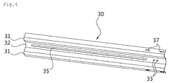
- the guardrail 30 is a substantially rectangular plate that is fabricated to extend in one direction.
- the guardrail 30 is formed with peaks 31 and valleys 32 to extend parallel to each other in the longitudinal direction so as to reinforce the strength of the guardrail 30.
- the peaks 31 and the valleys 32 are alternately formed, and the arrangements thereof are opposite to each other on both surfaces of the guardrail 30.
- fixing and fastening holes 33 are formed in one end portions of the guardrail 30, fixing and fastening holes 33 are formed. In the present embodiment, two fixing and fastening holes 33 are formed. However, two or more fixing and fastening holes may be formed.
- a rail long-hole 35 is formed in a slot shape along the widthwise center of the guardrail 30 to be elongated in the longitudinal direction. As can be seen from FIG. 4 , the rail long-hole 35 is formed over almost all the region of the guard rail 30 except the opposite end portions of the guardrail 30 in the longitudinal direction.
- the rail long-hole 35 is provided so as to allow the guardrail 30 to be relatively moved in relation to the support column 10 connected thereto when a head-on collision is applied. That is, when third fasteners 38 to be described below, which fasten the guardrail 30 to the rail bracket 20, penetrate the rail long-hole 35, the guardrail 30 can be moved by a force (shock) of a predetermined level even if third fasteners 38 are fastened to the rail bracket 20 of the support column 10.
- connection rail fastening holes 37 for fastening a collision head 40 to be described.
- the connection rail fastening holes 37 are formed only in the guardrail 30 used at the endmost portion among the guardrails 30, in which one pair of holes are formed at each side of one end of the guardrail 30. That is, a total of four holes are formed.
- the number of the connection rail fastening holes 37 is not necessarily limited to that illustrated in the present embodiment. Two or more connection rail fastening holes 37 may be formed at each side of the end of the guardrail 30. This is to rigidly fix the collision head 40 such that collision head 40 is not movable.
- the third fasteners 38 are used.
- the third fasteners 38 are fastened in a state where a spacer bar 39 is positioned on the outer surface of a guardrail 30. That is, the third fasteners 38 are fastened through the spacer bar 39, the rail long-hole 35 of a guardrail 30 of one side, the fixing and fastening holes 33 of a guardrail 30 of the other side, and the mounting holes 22 of a rail bracket 20.
- bolts and nuts may also be used as the third fasteners 38.
- the spacer bar 39 functions to compress the third fasteners 38 while causing the fastening force of the third fasteners 38 to uniformly act on a wider region of the guardrail 30.
- the spacer bar 39 is formed in an approximately rectangular shape, and has extension portions extending at a very small inclination from the opposite ends thereof so that the spacer bar 39 can be in close contact with the outer surface of the guardrail 30 in a state where the spacer par 39 is slightly elastically deformed.
- the spacer bar 39 is also formed with two through-holes (no reference numeral is given).
- a plurality of support columns 10 are used and guardrails 30 are mounted on both sides of each of the support columns 10, respectively, so that a plurality of guardrails 30 are used.
- the guardrails 30 should be arranged such that the inner surface of a guardrail 30 of one side is seated on the outer surface of the next guardrail 30.
- the guardrails 30 may be arranged such that the outer surface of a guardrail 30 of one side may be arranged to be seated on the inner surface of the next guardrail 30.
- the collision head 40 is attached to a portion corresponding to the front end of the apparatus of the present invention so as to widen the collision surface when a vehicle collides with the collision head 40, thereby preventing the front end of the guardrail 30 from penetrating the vehicle.
- the collision head 40 is provided with a collision plate 41.
- the collision plate 41 is attached to the end of the guardrail 30 at a position corresponding to the widthwise central portion of the rear surface of the collision plate 41.
- a nose position 42 is installed on the front surface of the collision plate 41.
- the nose portion 42 is made of a high-density PE plate in an arch shape. The nose portion 42 is provided so as to alleviate the psychological burden of drivers and to improve the external appearance.
- connection rail 44 to be connected with the guardrail 30 is provided.
- the cross-sectional configuration of the connection rail 44 is the same as that of the guardrail 30. This is to allow the connection rail 44 to be connected to the guardrail 30 in the state where the connection rail 44 partially overlaps the guardrail 30.
- connection rail 44 is also formed with fastening holes 45, through which the fourth fasteners 47 can pass, at the positions corresponding to the connection rail fastening holes 37, so that the connection rail 44 is fastened to the guardrail 30 by using the fourth fasteners 47.
- the fourth fasteners 47 are fastened through the fastening holes 45 and the connection rail fastening holes 37 so that the connection rail 44 and the guardrail 30 are fastened to each other.
- the connection rail 44 is fastened to the rail bracket 20 placed on the support column 10 together with the first guardrail 30 by using the third fasteners 38 and the spacer bar 39.
- connection cable 50 is provided so as to connect the first support column 10 and the second support column 10 with each other.
- the connection cable 50 is made of a steel wire rope, and is used so as to reinforce resistance against a side collision. Both ends of the connection cable 50 are provided with connecting links 51.
- the connecting links 51 are made by forming each end portion of the connection cable 50 in a closed curve shape.
- a cable bracket 52 is provided on a side of the first support column 10. To the cable bracket 52, the connecting link 51 at one side of the connection cable is hooked.
- a sleeve 54 is fixed to the rail bracket 20 by welding, and an eye-bolt 56 is installed through the sleeve 54. Since a connecting ring 57 is present on one end of the eye-bolt 56, the other end of the connection cable 50 is hooked to the connecting ring 57.
- a nut 58 is fastened in a state where the sleeve 54 is penetrated by the eye-bolt 56. Depending on the fastened position of the nut 58 on the eye-bolt 56, the tension of the connection cable 50 is adjusted.
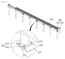
- FIGS. 9 to 12 illustrate another embodiment of the present invention.
- the constituent elements corresponding to those described above are denoted by 100-added reference numerals, and only the major components will be described.
- support columns 110 are installed in a row on the ground 1 at a predetermined interval.
- Each of the support columns 110 includes a lower column part 111 installed by being buried in the ground, and an upper column part 112 coupled to the top end of the lower column part 111.
- the guardrails 130 are installed along both sides of the support columns 110.
- two connection rails 144 are provided on the rear surfaces of the collision plate 141 of the collision head 140. This is due to the fact that the guardrails 130 are provided on both sides of the upper column parts 112.
- the structure of installing the guardrails 130 to the support columns 110, the structure of arranging the guardrails 130 are substantially the same as the embodiment described above.
- the structure, in which the guardrails 130 are disposed on both sides of the support columns 110 as described above, will be used when such a structure is installed along the centerline of a road or when a structure of a high level is required even if such a structure is installed on a side of the road.
- the connection cable may not be used.
- FIG. 13 the configuration of another embodiment of the present invention illustrated in FIG. 13 will be described.
- the constituent elements corresponding to those of the embodiment described above are denoted by 200-added reference numerals and only the major components will be described.
- an anchor plate 211' is provided on each of the lower column parts 211.
- the anchor plate 211' serves to fix the corresponding lower column part 211 to the ground. That is, by anchoring the anchor plate 211' to the ground by using an anchor bolt, it is not necessary to dig in the ground in order to install the lower column part 211.
- first connection flange 214 installed on the lower column part 211 and the second connection flange 216 installed on the upper column part 212 are installed to be inclined in relation to the ground. That is, the first connection flange 214 is installed on the upper end of the lower column part 211 to be inclined in relation to the height direction of the lower column part 211, and the second connection flange 216 is installed on the lower end of the upper column part 212 to have the same inclined angle as the first connection flange 214.
- the first connection flange 214 and the second connection flange 216 are inclined such that they are upwardly inclined in the direction where the upper column part 212 moves when a head-on collision occurs. This is to prevent the upper column part 212 from being disturbed by an object protruding from the ground in the vicinity of the support column 210 while the upper column part 212 is moving.
- a guide portion 214' is formed on the first connection flange 214 at an end of the guide portion 214' located at a relatively lower position.
- the guide portion 214' serves to guide the second connection flange 216 of the upper column part 212 that is moving in, to the guide portion 214'. That is, the guide portion 214' is to allow the second connection flange 216 of the moving-in upper column part 212 to easily move onto the first connection flange 214 of the lower column part 211 fixed to the ground without being caught to the other portion.
- FIG. 14 illustrates still another embodiment of the present invention. In the present embodiment, also for the convenience of description, the constituent elements corresponding to those described above will be denoted by 300-added reference numerals, and only the principal components will be described.
- a first connection flange 314 is provided on the upper end of a lower column part 311 buried in the ground, and a guide portion 314' protrudes from the first connection flange 314.
- the guide portion 314' guides the second connection flange 316 placed on the upper column part 312 that is moving in, to the upper side of the first connection flange 314.
- the guide portion 314' is formed to be downwardly inclined toward an adjacent support column 310. That is, the guide portion 314' is integrally formed at one end of the first connection flange 314 and is bent to be downwardly inclined toward the adjacent support column 310. In the present embodiment, the first connection flange 314 is installed parallel to the ground.
- FIG. 15 illustrates still another embodiment of the present invention.
- the constituent elements corresponding to those described above will be denoted by 400-added reference numerals, and only the principal components will be described.
- a lower column part 411 that constitutes a support column 410 is installed to the ground through an anchor plate 411'. That is, the lower column part 411 is fixed to the ground by anchor bolts rather than being buried in the ground.
- an anchor plate 411' is integrally provided at the lower end of the lower column part 411.
- a first connection flange 414 is provided on the upper end of the lower column part 411 and a guide portion 414' protrudes from the first connection flange 414.
- the guide portion 414' guides the second connection flange 416 placed on the upper column part 412 that is moving in, to the upper side of the first connection flange 414.
- the guide portion 414' is formed to be downwardly inclined toward an adjacent support column 410. That is, the guide portion 414' is integrally formed at one end of the first connection flange 414 and is bent to be downwardly inclined toward the adjacent support column 410. In the present embodiment, the first connection flange 414 is installed parallel to the ground.
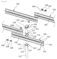
- FIGS. 16 to 19 illustrate still another embodiment of the present invention.
- the support columns 510 are installed to the ground 1.
- the support columns 510 are installed to a median strip or a ground 1 of a road side.
- Each support column 510 is divided into a lower column part 511 and an upper column part 512.
- the greater part of the lower column part 511 is buried under the ground 1, and upper column part 512 is installed such that the upper column part 512 is connected to the lower column part 511 and protrudes upwardly.
- the lower column part 511 and the upper column part 512 are formed in a cylindrical shape, but it is not absolutely the case.
- the support column 510 may have various shapes from, for example, a pipe with a polygonal cross section, a C-shape pipe, and an H-beam.
- a first connection flange 514 is provided on the upper end of the lower column part 511.
- the first connection flange 514 has a plate shape and protrudes over the outer surface of the lower column part 511 on the upper end of the lower column part 511. From the front end of the first connection flange 514, a guide portion 514' protrudes. When an adjacent upper column part 512 moves in when a head-on collision occurs, the guide portion 514' allows a second connection flange 516, which is placed on the upper column part 512 that moves in to the upper side of the first connection flange 514, to be smoothly guided to the top surface of the first connection flange 514.
- the first connection flange 514 is formed with first opened fastening holes 515.
- First fasteners 519 to be described are inserted through the first opened fastening holes 515.
- Two first opened fastening holes 515 are formed at each of the opposite ends of the first connection flange 514. That is, a total of four first opened fastening holes 515 are formed in the first connection flange 514.
- the number of the first opened fastening holes 515 may vary according to a design condition. While the first opened fastening holes 515 are formed at the opposite ends of the first connection flange 514 in the present embodiment, they may be formed at only one end of the first connection flange 514.
- the first opened fastening holes 515 are opened such that the centers are not seen in a side collision direction when viewed with reference to the edges of the first connection flange 514.
- the opened direction of each of the first opened fastening holes 515 is inclined in relation to a head-on collision direction, and a first guide slope 515' is formed to be inclined along one side of the opened portion.
- the first opened fastening holes 515 are formed such that the centers thereof are not directly seen when viewed from the edges of the first connection flange 514, and with this configuration, each of the first opened fastening holes 515 is formed with a blocking protrusion 515" .
- the blocking protrusions 515" prevent the first opened fastening holes 515 from being directly opened in the side collision direction of the first connection flange 514, and thus, when a side collision occurs, the blocking protrusions 515" serve to hold the first fasteners 519 such that the first and second connection flanges 514 and 516 do not move in relation to each other.
- connection flange 516 is provided below the upper column part 512.
- the second connection flange 516 is formed in the same shape as the first connection flange 514.
- first and second connection flanges 514 and 516 are not necessarily made to have the same shape.
- second opened fastening holes 517 are formed at the positions that correspond to the first opened fastening holes 515, respectively.
- the centers of the first opened fastening holes 515 may coincide with the centers of the second opened fastening holes 517, respectively.
- Each of the second opened fastening holes 517 is also opened to one side thereof. Unlike the first opened fastening holes 515, the second opened fastening holes 517 are opened such that the centers thereof are seen in the side collision direction when viewed with reference to the edges of the second connection flange 516.
- the opened directions of the second opened fastening holes 517 are also inclined in relation to the head-on collision direction, and a second guide slope 517' is formed to be inclined along a side of the opened portion of each of the second opened fastening holes 517.
- the inclined direction of the second guide slopes 517' is opposite to the inclined direction of the first guide slopes 515'.
- Each second opened fastening hole 517 is formed to be opened to one side, in which the opened direction of the second opened fastening hole 517 is a direction orthogonal to the direction facing the adjacent support column 510, that is, the side collision direction.
- the arrangement of the first opened fastening holes 515 formed in the first connection flange 514 and the arrangement of the second opened fastening holes 517 formed in the second connection flange 516 in the present embodiment are positioned opposite to those of the embodiment illustrated in FIG. 1 . That is, the arrangement of the first opened fastening holes 15 of the embodiment illustrated in FIG. 1 is the same as that of the second opened fastening holes 517, and the arrangement of the second opened fastening holes 17 of the embodiment illustrated in FIG. 1 are the same as that of the first opened fastening holes 515.
- the opened fastening holes 515 and 517 may be formed in any of the first and second connection flanges 514 and 516. This is also applicable to all the other embodiment of the present specification.
- the first and second connection flanges 514 and 516 are fastened to each other by the first fasteners 519.
- an example of the first fasteners 519 includes bolts and nuts.
- the first fasteners 519 may be inserted through, for example, both the first fastening holes 515 of the first connection flange 514 and the second opened fastening holes 517 of the second connection flange 516, respectively.
- a total of four first fasteners 519 are used for fastening the first and second connection flanges 514 and 516.
- the support column 510 is provided with a rail bracket 520. More precisely, a rail bracket 520 is installed to the upper end of the upper column part 512 so as to mount a guardrail 530 to be described below.
- the rail bracket 520 is formed with a mounting hole 522.
- the rail bracket 520 of the present embodiment is illustrated in a plan view, the rail bracket 520 is formed substantially in a " ⁇ " shape, so that the guardrail 530 to be described below is mounted at a positon spaced apart from the outer surface of the upper column part 512 by a predetermined distance.
- the rail bracket 520 is mounted on a connector 524 fastened to the upper column part 512.
- both the mounting of the rail bracket 520 on the connector 524 and the fastening of the connector 524 to the upper column part 512 are performed by second fasteners 526.
- second fasteners 526 bolts and nuts are employed.
- guardrails 530 are provided along both sides of the support columns 510. Accordingly, the rail brackets 520 are provided on both sides of each of the support columns 510.
- the guardrail 530 is a substantially rectangular plate that is made to be elongated in one direction.
- peaks 531 and valleys 532 are formed parallel to each other and to extend in the longitudinal direction of the guardrail 530.
- the arrangements of the peaks 531 and valleys 532, which are alternately formed, are opposite to each other on the both side surfaces of the guard rail 530.
- Fixing and fastening holes 533 are formed in one end of the guardrail 530. Although two fixing and fastening holes 533 are formed in the present embodiment, the number of the fixing and fastening holes 533 may be two or more.
- the fixing and fastening holes 533 are provided so as to fasten the support column 510 to a guardrail 530 using third fasteners 538 to be described below.
- a rail long-hole 535 is formed in the guard rail 530 in a slot shape to extend in the longitudinal direction along the widthwise center of the guardrail 530. As can be seen from FIG. 18 , the rail long-hole 535 is formed over almost all the region of the guard rail 530 except both ends of the guardrail 530 in the longitudinal direction.
- an interlocking step 536 at a position corresponding to the rail long-hole 535.
- the interlocking step 536 serves to smoothen the movement of the guardrail 530 by allowing the spacer bars 539 and 539' , which are positioned at the rear end, to enter to the inner surface side of the guardrail 530 when the guardrail 530 has moved in.
- connection rail fastening holes 537 for fastening a collision head 540 to be described below.
- the connection rail fastening holes 537 are formed only in the guardrail 530 to be used at the endmost portion and one pair of connection fastening holes 537 are formed at each side of one end of the guardrail 530. That is, a total of four connection fastening holes 537 are formed.
- the number of the connection rail fastening holes 537 is not necessarily limited to that illustrated in the present embodiment.
- Two or more connection rail fastening holes 537 may be formed at each side of the end of the endmost guardrail 530. This is to rigidly fix the collision head 540 such that the collision head 540 is not movable.
- third fasteners 538 are used.
- the third fasteners 538 are fastened in a state where a first spacer bar 539 is positioned on the outer surface of a guardrail 530. That is, the third fasteners 538 are fastened through the first spacer bar 539, a rail long-hole 535 of an outer guardrail 530, a fixing and fastening holes 533 of an inner guardrail 530, and the mounting holes 522 of the rail bracket 520.
- bolts and nuts may also be used as the third fasteners 538.
- a second spacer bar 539' is installed adjacent to the first spacer bar 539.
- a second spacer bar 539' is positioned at a relatively rear end side in relation to the first spacer bar 539, that is, at the opposite side to the collision head 540 to be described below.
- the third fasteners 538 inserted through the second spacer bar 539' are fastened to a close contact bracket 539" through the second spacer bar 539', the rail long-hole 535 of the outer guardrail 530, through the rail long-holes 535 of the inner guardrail 530.
- the close contact bracket 539" has a shape corresponding to that of a part of the inner surface of the guardrail 530, and is installed to be in close contact with the inner surface of the guardrail 530.
- the close contact bracket 539" is formed with fastening holes 539s so that the third fasteners 538 are fastened thereto.
- the spacer bars 539 and 539' serve to compress such that the fastening force of the third fasteners 538 uniformly acts on a wider region of the guardrail 530.
- the spacer bars 539 and 539' are formed in a substantially rectangular plate shape and have portions extending at a very small inclination at both ends thereof so that the spacer bars 539 and 539' can be in close contact with the outer surface of the guardrail 530 in a slightly elastically deformed state.
- the spacer bars 539 and 539' are also formed with two through-holes (no reference numeral is assigned) so that the third fasteners 538 pass therethrough.
- a plurality of support columns 510 are arranged in a row to be used, and guardrails 530 are mounted on both sides of the support columns 510 so that a plurality of guardrails 530 are used.
- the guardrails 530 should be arranged such that the inner surface of a guardrail 530 of one side is seated on the outer surface of the next guardrail 530.
- the guardrails 530 may be arranged such that the outer surface of a guardrail 530 of one side may be arranged to be seated on the inner surface of the next guardrail 530.
- the collision head 540 is attached to a portion corresponding to the front end of the apparatus of the present invention so as to widen the collision surface when a vehicle collides with the collision head 540, thereby preventing the front end of the guardrail 530 from penetrating the vehicle.
- the collision head 540 is provided with a collision plate 541.
- the collision plate 541 is attached to the end of the guardrail 530 at a position corresponding to the widthwise central portion of the rear surface of the collision plate 541.
- a nose position 542 is installed on the front surface of the collision plate 541.
- the nose portion 542 is made of a high-density PE plate in an arch shape. The nose portion 542 is provided so as to alleviate drivers' psychological burden and improve an external appearance.
- connection rail 544 to be with the guardrail 530 is provided on the rear surface of the collision plate 541.
- the cross-sectional configuration of the connection rail 544 is the same as that of the guardrail 530. This is to allow the connection rail 544 to be connected to the guardrail 530 in the state where the connection rail 544 partially overlaps the guardrail 530.
- connection rail 544 is also formed with fastening holes 545, through which the fourth fasteners 547 can pass, at the positions corresponding to the connection rail fastening holes 537, so that the connection rail 544 is fastened to the guardrail 530 by using the fourth fasteners 547.
- the fourth fasteners 547 are fastened through the fastening holes 545 and the connection rail fastening holes 537 so that the connection rail 544 and the guardrail 530 are fastened to each other.
- the connection rail 544 is fastened to the rail bracket 520 placed on the support column 510 together with the first guardrail 530 by using the third fasteners 538 and the first spacer bar 539.
- guardrail end shock absorbing device having the configuration as described above according to the present invention will be described in detail.
- FIG. 1 illustrates a state in which the shock absorbing device of the present invention is installed.
- the device of the present invention is installed to be placed in an end of a general guardrail assembly.
- seven support columns 10 are installed to the ground 1.
- the guardrails 30 are installed to one side of the support columns 10 and arranged to be stacked sequentially such that each two adjacent support columns 10 partially overlap each other.
- connection rail 44 is fastened to the upper column part 12 together with the guardrails 30, the collision head 40, the connection rail 44, the guardrail 30 of the endmost side, and the upper column part 12, to which the guardrail 30 of the endmost side is fastened, are moved in unison.
- the upper column part 12 of the first support column 10 should be separated from the lower column part 11.
- the upper column part 12 should be relatively moved in relation to the lower column part 11 due to the configuration of the first opened fastening holes 15 and the second opened fastening holes 17 that are formed in the first connection flange 14 and the second connection flange 16, respectively.
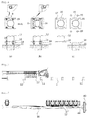
- FIG. 6a illustrates a state in which the first and second connection flanges 14 and 16 of the upper column part 12 and the lower column part 11 are coupled to each other by the first fasteners 19
- FIG. 6b illustrates an intermediate step in which the upper column part 12 is separated as a collision is applied thereto in a direction A
- FIG. 6c illustrates a state where the collision is continuously applied to the upper column part 12 so as to move the upper column part 12 such that the first fasteners 19 are completely released to the outside of the first and second connection flanges 14 and 16 and the upper column part 12 is completely separated from the lower column part 11.
- the upper column part 12 is moved in relation to the lower column part 11 installed to the ground, and the upper column part 12 separated from the lower column part 11 begins to move together with the guardrail 30.
- the state in which the spacer bar 39 is in close contact with the rail bracket 20 by the third fasteners 38 should be overcome. That is, since the spacer bar 39 is in close contact with the valley 32 of the guardrail 30 as the third fasteners 38 are tightened with a predetermined torque, the shock is absorbed as the frictional force, generated therebetween when the guardrail 30 is moved, is turned into and dissipated as heat.
- the third fasteners 38 which have passed through the fixing and fastening holes 33 of the adjacent guardrail 30, passes through the rail long-hole 35. Accordingly, the third fasteners 38, which have passed the fixing and fastening holes 33 of the adjacent guardrail 30, are guided along the rail long-hole 35 of the guardrail 30 of the collision head 40 side.
- the third fasteners 38 which are fastened to the upper column part 12 together with the first guardrail 30, pass through the fixing and fastening holes 33 in the second guardrail 30. Accordingly, the second guardrail 30 and the second upper column part 12 can be moved in unison.
- the third fasteners 38 which are fastened to the upper column part 12 together with the third guardrail 30, pass through the rail long-hole 35 of the second guardrail 30, the second guardrail 30 can be moved in relation to the third guardrail 30.
- the guard rails 130 are arranged on both sides of the support columns 110, the guardrails 130 of both sides are also moved in unison so that the movement of the upper column parts 112 will be generated along a predetermined track.
- the front end of the second connection flange 216 in the moving direction is adapted to be directed toward a relatively higher side.
- the second connection flange 216 can move without interference with a peripheral object so that the operation of the entire device can be smoothly performed.
- the guide portion 314' is formed at one end of the first connection flange 314 installed to the upper end of the lower column part 311 is bent to be inclined downwardly toward the ground. Accordingly, the guide portion 314' can move the second connection flange 316 of the upper column part 312, which is separated from the adjacent support column 310 and moved in, onto the first connection flange 314, so that the operation of the device can be performed smoothly.
- the anchor plate 411' of the lower column part 411 is configured to be fixed to the ground by anchor bolts, and when the upper column part 412 of the adjacent support column 410 is separated and moved in, second connection flange 416, which is moved in together with the upper column part 412, is guided onto the first connection flange 414, so that the operation of the device can be performed smoothly.
- the first spacer bar 539 and the second spacer bar 539' connect the guardrails 530, which are adjacent to overlap each other.
- the third fasteners 538 that pass through the first spacer bar 539 are fastened to the mounting holes 522 of the rail bracket 520 through the rail long-hole 535 of the outer guardrail 530 and the fixing and fastening holes 533 of the inner guardrail 530.
- the third fasteners 538 which pass through the second pacer bar 539', pass both the rail long-hole 535 of the outer guardrail 530 and the rail long-hole 535 of the inner guardrail 530 to be fastened to the fastening holes 539s of the close contact bracket 539".
- the second spacer bar 539' also generates friction with the guardrail 530 to absorb shock. Accordingly, relatively large shock can be absorbed.
- the interlocking step 536 guides the spacer bars 539 and 539' to enter to the inner surface side of the guardrail 530 without being caught by the rear end of the guardrail 530 so that friction is generated well between the spacer bars 539 and 539' and the inner surface of the guardrail 530.
- the second connection flange 516 of the upper column part 512 is guided by the guide portion 514' of the first connection flange 514 of the lower column part 511 to be smoothly moved along the top surface of the first connection flange 514 so that the operation of the entire shock absorbing device is performed smoothly.
- first and second opened fastening holes 15 and 17, which enables the relative movement of the upper column part 12 in relation to the lower column part 11, may be opened in the edges of the first and second connection flange in various forms other than those illustrated in the drawings. That is, in the embodiments described above, all the opened fastening holes 15 and 17 are provide with first and second guide slopes 15' and 17' at opposite sides of the side collision direction to be inclined in the direction of the opened edge directions, respectively. However, specific configurations or the like of the guide slopes 15', 17' may be different from each other.
- respective configurations in the illustrated embodiments may be combined with each other so as to make another embodiment.
- the support columns 10, 110, 210, 310, 410, and 510 have different configurations
- the configurations of the support columns 10, 110, 210, 310, 410, and 510 may be variously combined in each of the illustrated embodiments.
- the inclined first and second connection flanges 214 and 216 of the embodiment of FIG. 13 may also be applied to the embodiment illustrated in FIG. 1 or FIG. 9 .
- connection rails 44 and 544 connected with the collision head 40 are not necessarily required.
- the collision head 40 may be directly connected to the guardrail 530.
- the end shock absorbing device enables shock, which is applied when a vehicle collides head-on therewith, to be smoothly absorbed as well as prevents a support column from being damaged by shock, which is applied when a vehicle collides laterally therewith. Accordingly, when the end shock absorbing device is installed on a road, safe driving of vehicles can be secured more reliably by preventing the vehicles from getting out of the road, and elements that constitute the end shock absorbing device as described above can be manufactured in an industrial manner.
Landscapes
- Engineering & Computer Science (AREA)
- Architecture (AREA)
- Civil Engineering (AREA)
- Structural Engineering (AREA)
- Refuge Islands, Traffic Blockers, Or Guard Fence (AREA)
Applications Claiming Priority (3)
| Application Number | Priority Date | Filing Date | Title |
|---|---|---|---|
| KR20130042804 | 2013-04-18 | ||
| KR1020130092255A KR101339447B1 (ko) | 2013-04-18 | 2013-08-02 | 가드레일 단부 충격흡수장치 |
| PCT/KR2014/003137 WO2014171672A1 (ko) | 2013-04-18 | 2014-04-11 | 가드레일 단부 충격흡수장치 |
Publications (2)
| Publication Number | Publication Date |
|---|---|
| EP2987914A1 true EP2987914A1 (de) | 2016-02-24 |
| EP2987914A4 EP2987914A4 (de) | 2016-12-07 |
Family
ID=49987870
Family Applications (1)
| Application Number | Title | Priority Date | Filing Date |
|---|---|---|---|
| EP14786109.0A Withdrawn EP2987914A4 (de) | 2013-04-18 | 2014-04-11 | Stossdämpfende vorrichtung für leitplankenende |
Country Status (3)
| Country | Link |
|---|---|
| EP (1) | EP2987914A4 (de) |
| KR (1) | KR101339447B1 (de) |
| WO (1) | WO2014171672A1 (de) |
Cited By (1)
| Publication number | Priority date | Publication date | Assignee | Title |
|---|---|---|---|---|
| CN111501624A (zh) * | 2020-05-28 | 2020-08-07 | 天台台润交通设施有限公司 | 一种快装护栏 |
Families Citing this family (15)
| Publication number | Priority date | Publication date | Assignee | Title |
|---|---|---|---|---|
| KR101835101B1 (ko) * | 2014-07-04 | 2018-03-08 | 정도산업 주식회사 | 가드레일 단부 충격흡수장치 |
| KR101471067B1 (ko) * | 2014-07-15 | 2014-12-10 | 동아에스텍 주식회사 | 중앙 분리대 단부처리 구조체 |
| KR101659995B1 (ko) * | 2015-07-09 | 2016-09-26 | 채종술 | 충격흡수형 도로용 단부시설물 |
| KR101638290B1 (ko) * | 2015-07-27 | 2016-07-08 | 우신그린산업(주) | 가드레일 단부 충격흡수장치 |
| KR101749544B1 (ko) | 2015-10-20 | 2017-06-21 | 정도산업 주식회사 | 가드레일 지주어셈블리 및 이를 구비하는 가드레일 단부 완충장치 |
| KR101683851B1 (ko) | 2016-03-07 | 2016-12-09 | (주) 금동강건 | 단부 충격흡수장치가 구비된 도로용 가드레일 |
| KR101974968B1 (ko) * | 2016-08-31 | 2019-05-03 | 채종술 | 충격 흡수형 단부시설물 |
| KR101964396B1 (ko) * | 2016-12-09 | 2019-04-01 | 주식회사 온길 | 방호울타리 단부 충격흡수장치 |
| KR101898252B1 (ko) * | 2017-10-12 | 2018-10-25 | 다스코 주식회사 | 가드레일의 단부처리 구조체 시공방법 |
| KR102130154B1 (ko) * | 2017-12-19 | 2020-07-03 | 주식회사 국제에스티 | 가드레일 단부의 충격흡수장치 |
| KR101902962B1 (ko) * | 2018-01-16 | 2018-10-08 | 다스코 주식회사 | 충격흡수 구조체 |
| KR102239903B1 (ko) | 2020-11-03 | 2021-04-13 | 세라코 주식회사 | 가드레일이 장착된 분리형 충격흡수시설 |
| CN115288061B (zh) * | 2022-08-03 | 2025-03-18 | 北京中路安交通科技有限公司 | 一种分离弯、剪受力的波形梁护栏结构及其布设方法 |
| CN116220457B (zh) * | 2022-12-29 | 2023-08-18 | 山东赛纳石油科技有限公司 | 智能间距可调的井场间距护栏 |
| KR102747308B1 (ko) * | 2024-08-22 | 2024-12-27 | 주식회사 가온씨앤디 | 어린이 보호구역에 주행안내등이 구비된 방호울타리 |
Family Cites Families (11)
| Publication number | Priority date | Publication date | Assignee | Title |
|---|---|---|---|---|
| AU583726B2 (en) * | 1986-05-01 | 1989-05-04 | Energy Absorption Systems Inc. | Highway barrier |
| US5775675A (en) | 1997-04-02 | 1998-07-07 | Safety By Design, Inc. | Sequential kinking guardrail terminal system |
| KR200150858Y1 (ko) | 1997-04-25 | 1999-07-15 | 김기중 | 안전성이 강화된 가드레일(Guard rail) |
| KR200272031Y1 (ko) | 2002-01-09 | 2002-04-13 | 윤길호 | 충격을 흡수하는 가드레일 및 가드레일 충격흡수판. |
| KR200281806Y1 (ko) | 2002-03-18 | 2002-07-13 | 안세준 | 충격흡수 및 높이조절이 가능한 도로 가드레일 |
| KR100727058B1 (ko) * | 2006-09-21 | 2007-06-12 | 재 술 나 | 충격흡수용 가드레일 |
| KR100912464B1 (ko) | 2007-10-18 | 2009-08-14 | 한국도로공사 | 단부 충격흡수기능이 구비된 가드레일장치 |
| KR20100007313U (ko) * | 2009-01-08 | 2010-07-16 | 김훈식 | 가드레일 보강제 지주 완충 충격흡수 패킹 |
| KR20120007395A (ko) * | 2010-07-14 | 2012-01-20 | 동원엔지니어링(주) | 충격흡수성 및 형태복원성을 보강한 가드레일구조물 |
| KR101215087B1 (ko) * | 2011-06-21 | 2012-12-24 | (주)대흥이엔지 | 충격흡수용 방호울타리 |
| KR101141690B1 (ko) * | 2011-12-06 | 2012-05-04 | 주식회사 현대표지 | 비대칭 충격흡수부재가 장착된 가드레일 |
-
2013
- 2013-08-02 KR KR1020130092255A patent/KR101339447B1/ko active Active
-
2014
- 2014-04-11 WO PCT/KR2014/003137 patent/WO2014171672A1/ko not_active Ceased
- 2014-04-11 EP EP14786109.0A patent/EP2987914A4/de not_active Withdrawn
Cited By (1)
| Publication number | Priority date | Publication date | Assignee | Title |
|---|---|---|---|---|
| CN111501624A (zh) * | 2020-05-28 | 2020-08-07 | 天台台润交通设施有限公司 | 一种快装护栏 |
Also Published As
| Publication number | Publication date |
|---|---|
| KR101339447B1 (ko) | 2013-12-10 |
| EP2987914A4 (de) | 2016-12-07 |
| WO2014171672A1 (ko) | 2014-10-23 |
Similar Documents
| Publication | Publication Date | Title |
|---|---|---|
| EP2987914A1 (de) | Stossdämpfende vorrichtung für leitplankenende | |
| US10900182B2 (en) | Vehicle safety catch fence | |
| ES2712149T3 (es) | Barrera de seguridad | |
| US7731159B2 (en) | Continuous metallic system for safety barriers applicable as protection for motorcyclists made up of a bottom continuous horizontal metallic screen supported on the barrier by means of metallic arms arranged at regular intervals | |
| MX2011010257A (es) | Ensamble de valla de seguridad, poste de soporte de separacion para una valla de seguridad y metodos para el ensamble y uso de los mismos. | |
| KR101448982B1 (ko) | 충격흡수장치 | |
| US10851503B2 (en) | Tension end treatment for guardrail safety system | |
| US8960647B2 (en) | Barrier system | |
| KR101670836B1 (ko) | 가드레일 연결형 충격흡수장치 | |
| KR101283970B1 (ko) | 도로변의 동, 식물 차단장치 | |
| KR101911241B1 (ko) | 생태통로 유도용 안전난간 | |
| US20060243954A1 (en) | High tension cable to metal beam guide fence transition | |
| KR100970934B1 (ko) | 차량 방호 울타리 | |
| KR20090048222A (ko) | 도로 가드레일의 동물 진입 차단장치 | |
| GB2450352A (en) | Wire rope vehicle restraining fence | |
| KR101259931B1 (ko) | 가드레일 단부 충격흡수장치 | |
| KR100872088B1 (ko) | 차량용 방호울타리 | |
| KR20050032561A (ko) | 도로용 가드레일 | |
| JP2023041907A (ja) | ケーブル式道路防護柵用支柱 | |
| KR101898252B1 (ko) | 가드레일의 단부처리 구조체 시공방법 | |
| KR102429514B1 (ko) | 태양광패널 부착용 완충부재를 구비한 차량 방호울타리 | |
| JP6345959B2 (ja) | 衝撃吸収柵 | |
| KR20160027702A (ko) | 차량방호울타리 레일 프레임 | |
| KR101214012B1 (ko) | 2단 가드레일 | |
| JP3680208B2 (ja) | ロープの間隔保持装置 |
Legal Events
| Date | Code | Title | Description |
|---|---|---|---|
| PUAI | Public reference made under article 153(3) epc to a published international application that has entered the european phase |
Free format text: ORIGINAL CODE: 0009012 |
|
| 17P | Request for examination filed |
Effective date: 20150825 |
|
| AK | Designated contracting states |
Kind code of ref document: A1 Designated state(s): AL AT BE BG CH CY CZ DE DK EE ES FI FR GB GR HR HU IE IS IT LI LT LU LV MC MK MT NL NO PL PT RO RS SE SI SK SM TR |
|
| AX | Request for extension of the european patent |
Extension state: BA ME |
|
| DAX | Request for extension of the european patent (deleted) | ||
| A4 | Supplementary search report drawn up and despatched |
Effective date: 20161109 |
|
| RIC1 | Information provided on ipc code assigned before grant |
Ipc: E01F 15/14 20060101AFI20161103BHEP |
|
| STAA | Information on the status of an ep patent application or granted ep patent |
Free format text: STATUS: THE APPLICATION IS DEEMED TO BE WITHDRAWN |
|
| 18D | Application deemed to be withdrawn |
Effective date: 20170607 |