EP2987944A1 - Screeninganordnung mit einem schnursystem und vorrichtung zur einstellung der schnurlänge - Google Patents
Screeninganordnung mit einem schnursystem und vorrichtung zur einstellung der schnurlänge Download PDFInfo
- Publication number
- EP2987944A1 EP2987944A1 EP15181360.7A EP15181360A EP2987944A1 EP 2987944 A1 EP2987944 A1 EP 2987944A1 EP 15181360 A EP15181360 A EP 15181360A EP 2987944 A1 EP2987944 A1 EP 2987944A1
- Authority
- EP
- European Patent Office
- Prior art keywords
- cord
- screening arrangement
- adjustment member
- receiving
- side rail
- Prior art date
- Legal status (The legal status is an assumption and is not a legal conclusion. Google has not performed a legal analysis and makes no representation as to the accuracy of the status listed.)
- Granted
Links
Images





Classifications
-
- E—FIXED CONSTRUCTIONS
- E06—DOORS, WINDOWS, SHUTTERS, OR ROLLER BLINDS IN GENERAL; LADDERS
- E06B—FIXED OR MOVABLE CLOSURES FOR OPENINGS IN BUILDINGS, VEHICLES, FENCES OR LIKE ENCLOSURES IN GENERAL, e.g. DOORS, WINDOWS, BLINDS, GATES
- E06B9/00—Screening or protective devices for wall or similar openings, with or without operating or securing mechanisms; Closures of similar construction
- E06B9/56—Operating, guiding or securing devices or arrangements for roll-type closures; Spring drums; Tape drums; Counterweighting arrangements therefor
- E06B9/58—Guiding devices
-
- E—FIXED CONSTRUCTIONS
- E06—DOORS, WINDOWS, SHUTTERS, OR ROLLER BLINDS IN GENERAL; LADDERS
- E06B—FIXED OR MOVABLE CLOSURES FOR OPENINGS IN BUILDINGS, VEHICLES, FENCES OR LIKE ENCLOSURES IN GENERAL, e.g. DOORS, WINDOWS, BLINDS, GATES
- E06B9/00—Screening or protective devices for wall or similar openings, with or without operating or securing mechanisms; Closures of similar construction
- E06B9/24—Screens or other constructions affording protection against light, especially against sunshine; Similar screens for privacy or appearance; Slat blinds
- E06B9/40—Roller blinds
- E06B9/42—Parts or details of roller blinds, e.g. suspension devices, blind boxes
-
- E—FIXED CONSTRUCTIONS
- E06—DOORS, WINDOWS, SHUTTERS, OR ROLLER BLINDS IN GENERAL; LADDERS
- E06B—FIXED OR MOVABLE CLOSURES FOR OPENINGS IN BUILDINGS, VEHICLES, FENCES OR LIKE ENCLOSURES IN GENERAL, e.g. DOORS, WINDOWS, BLINDS, GATES
- E06B9/00—Screening or protective devices for wall or similar openings, with or without operating or securing mechanisms; Closures of similar construction
- E06B9/56—Operating, guiding or securing devices or arrangements for roll-type closures; Spring drums; Tape drums; Counterweighting arrangements therefor
- E06B9/58—Guiding devices
- E06B2009/583—Cords or cables
-
- E—FIXED CONSTRUCTIONS
- E06—DOORS, WINDOWS, SHUTTERS, OR ROLLER BLINDS IN GENERAL; LADDERS
- E06B—FIXED OR MOVABLE CLOSURES FOR OPENINGS IN BUILDINGS, VEHICLES, FENCES OR LIKE ENCLOSURES IN GENERAL, e.g. DOORS, WINDOWS, BLINDS, GATES
- E06B9/00—Screening or protective devices for wall or similar openings, with or without operating or securing mechanisms; Closures of similar construction
- E06B9/56—Operating, guiding or securing devices or arrangements for roll-type closures; Spring drums; Tape drums; Counterweighting arrangements therefor
- E06B9/58—Guiding devices
- E06B2009/587—Mounting of guiding devices to supporting structure
Definitions
- the present invention relates to a screening arrangement for a window adapted to be mounted in a frame of the window, having a supply condition and a mounted condition including at least two installation positions, the screening arrangement comprising a screening body and two side rails each defining a longitudinal direction between a lower end and an upper end, and having a predefined length corresponding to a first installation position, the side rails each being configured to form a break-off section and a remaining section for providing at least one adjusted length corresponding to a respective at least one other installation position, the adjusted length being shorter than the length of the side rail in the first installation position, the screening arrangement further comprising at least one cord system having a cord for guiding the screening body between a screening position and a non-screening position.
- the invention furthermore relates to a method of mounting such a screening arrangement in a window frame.
- the side rails positioned at the side pieces of the window serve i.a. the purpose of improving the light-proofing properties of the screening arrangement, as they overlap the side edges of the screening body. Furthermore, cords and other operating or guidance devices, which are present in the screening arrangement, are hidden behind the side rails. Eventually, depending on the type of screening body and the installation position, the side rails and the cords contribute to holding the screening body in position.
- such a side rail has a cross-section shaped substantially as an L or a T having two perpendicularly extending flanges, of which the first flange abuts the inner side face of the frame side piece, i.e. the face closest to the pane of the window.
- the second flange overlaps the side edges of the screening body etc. as described in the above, and possibly also part of the front face of the frame side piece.
- windows come in a number of different sizes entails that screening arrangements are traditionally delivered in a corresponding range of sizes.
- the side rails and the cords are delivered in predetermined sizes fitting the dimensions of the window to which the screening arrangement is installed.
- a window, which at first sight appears to be of identical size and model as another window might require a particular screening arrangement different from that of the other window so that the screening arrangement of one window might not be suitable to be mounted in another window.
- a need for providing a screening arrangement with adjustable parts fitting different kind of windows and which is easy to install is therefore of relevance.
- a screening arrangement comprising adjustment means including an extension member for connection to the side rail and other screening arrangement adapting means for adapting the screening arrangement to a particular installation position is suggested in Applicant's earlier published international application No. WO 2006/039926 A1 .
- this solution requires an adjustment of the cord to fit the adjusted side rail.
- a suitable solution for adjusting the cord length of the screening arrangement could be a simple shortening of the cord to fit the desired length of the particular installation.
- the shortening of the cord is often provided as an irreversible shortening, by simple cutting of an end of the cord to obtain the desired length or as by simply binding a knot on the cord so that knot not only shortens the cord but might also function as a stopping element.
- Another solution could be to wind up the cord onto an axle until the desired length is obtained, where the winding could for example be done by a user.
- the mounting of such solutions may be troublesome in that the screening arrangement often requires a specific cord tension fitting the dimensions of the screening arrangement for guiding of the screening body in a proper manner. Thus a certain length of the cord corresponding to the dimensions of the screening arrangement is required.
- a screening arrangement of the kind mentioned in the introduction which is furthermore characterized in that the cord system further comprises a cord adjustment means intended to be connected to at least a part of the frame and/or the side rail and having a tortuous path, the tortuous path having a predefined length corresponding to the length of the break-off section for providing an adjusted length of the cord in the at least one other installation position.
- the cord system By providing the cord system with a cord adjustment unit of this kind, the versatile applicability of one and the same side rail in more than one installation position aimed at is achieved, while at the same time maintaining a proper cord tensioning of the cord to guide the screening arrangement.
- the cord adjustment may simply take place by leading the cord in the tortuous path so that the cord length is adjusted, preferably shortened, to fit the length of the side rail in the at least one other installation position. In this way the cord may simply be adapted for use in two different installation positions of the window so that a preferred proper cord tension of the screening arrangement is maintained.
- the term "tortuous path" should be understood as any path in which a cord may be led or guided so that the effective length of the cord is adjusted. The path could simply be a loop or some way of winding up the cord in order to adjust the length to a predetermined length thereof.
- the adjustment of the side rails into the at least one other installation position may be obtained by simply bending the side rail about an axis parallel to a weakening portion.
- the side rails each includes at least one weakening portion such that a break-off section and a remaining section are formed of the side rail, the length of the remaining section corresponding to the at least one other installation position, and the length of the tortuous path corresponds to the length of the break-off section.
- the tortuous path may in this way be predetermined to a desired effective length of the cord so that the amount of cord which is wound up in the tortuous path preferably fits the length of the break-off section. In this way the adjusted length of the cord fits precisely the length of the adjusted side rail.
- the bending of the side rail may in principle take place in any direction, but bending the front sides of the break-off section and the remaining section towards each other results in the cleanest break surface.
- the cord adjustment means includes a cord adjustment unit having a receiving fitting and a cord holder configured to hold the cord, the receiving fitting in the mounted condition being arranged to be connected to the frame and/or the side rail, the receiving fitting in the mounted condition furthermore being configured to be connected to a cord adjustment member comprising the tortuous path.
- the tortuous path is configured so that the cord in the at least one other installation position is wound up in the cord adjustment member. Accordingly, the cord adjustment member provides for accommodating the remaining cord, which would otherwise extend beyond the length of side rail. In this way the cord may be adjusted prior to connecting the cord adjustment members and the receiving fitting so as to form the cord adjustment unit.
- the cord holder is configured to be connected to a first slit in the cord adjustment member and to a second slit in the receiving fitting, the first and second slits, in the mounted condition facing each other so that the cord holder in the at least one other installation position is accommodated in the first and second slits, the slits substantially having a shape corresponding to the shape of the cord holder.
- the cord holder is hidden in the cord adjustment unit.
- the cord holder is in a fixed position in the first and second slits so that an unintended adjustment of the cord is prevented.
- the predetermined length of the cord is kept in place so that the preferred cord tension of the screening arrangement is maintained after mounting.
- the slits having the same shape as the cord holder it provides the cord adjustment unit with an easy installation, which may be done by simply inserting the cord holder into either the first and second slit prior to connecting the receiving fitting and the cord adjustment member.
- the shape of the cord holder is substantially T-shaped.
- the tortuous path runs in the cord adjustment member substantially in a loop around the first slit of the cord adjustment member. Accordingly, the cord is led substantially in a loop around part of the interior of the cord adjustment member, so that the cord does not end up filtering together. This effects easy installation and the maintaining of a predetermined cord tensioning in the installation position, which again provides for a smooth operation of the screening arrangement.
- the tortuous path comprises cord guiding means for guiding the cord to the side rail.
- the cord is guided from the tortuous path of the cord adjustment member to the side rail without being filtered together or hanging loose from the screening arrangement.
- the guiding means also provides an easy installation, where the cord is simply clicked and/or snapped in to engagement with the guiding means where it is kept in place.
- the cord guiding means is provided in connection with the cord adjustment member so that the cord guiding means is configured as an entry groove for leading the cord from the tortuous path of the cord adjustment member to a guiding groove, the guiding groove leading the cord to an exit groove so that the cord is guided into the side rail in a direction towards the upper end of the side rail.
- the cord is guided in a precise manner to the side rail, so that a smooth operation of the screening arrangement is achieved. Accordingly, the cord is guided to the side rail so that it enters into a track of the side rail in a substantially longitudinal direction in relation to said track.
- this embodiment the ease of installation is improved since the cord is kept in place during mounting of the cord adjustment unit.
- the receiving fitting For mounting the cord adjustment unit to the frame and the side rail, the receiving fitting preferably comprises a mounting side intended to face a side piece of the window frame in the mounted condition and an opposite facing receiving side intended to be connected with a back side of the cord adjustment member, the mounting side having mounting means for mounting the receiving fitting to the side piece of the window frame and connecting means for connecting the receiving fitting to the side rail.
- the receiving side of the receiving fitting may thus in a further development of this embodiment comprise a first receiving means for connecting with an attachment means provided substantially on the back side of the cord adjustment member.
- Providing each of the receiving fitting and the cord adjustment member with means for connecting the two parts may thus facilitate an easy installation, where the attachment means of the cord adjustment member is simply clicked into the first receiving means of the receiving fitting. Therefore, no screws or additional mounting means are required for connecting the two parts.
- the side rail comprises a first leg adapted to be mounted on an inner side face of a side piece of a window frame and a second leg extending in a general plane at an angle to the first leg the first leg of the side rail is provided with a first flange portion extending substantially in parallel with the general plane of the second leg, a second flange portion at the free edge of the first flange portion, and a third flange portion extending substantially in parallel with the general plane of the second leg at a bottom part of the first leg.
- the connecting means of the receiving fitting is configured as a flange portion having a groove adapted to be engaged with the third flange portion of the first leg of the side rail so that the third flange portion is received in the flange portion.
- the connecting means is configured so that the groove is adapted to be engaged with the third flange portion of the first leg by a snap engagement.
- the snap engagement thus provides for a mounting situation without the need for using screws or other mounting means. The mounting may therefore be done by a user simply clicking the groove into the third flange portion of the first leg.
- the receiving fitting and the cord adjustment member is formed so that the receiving means of the receiving fitting and the connection means of the cord adjustment member may be connected through a snap engagement.
- the receiving fitting and the cord adjustment member in the mounted condition is mounted behind the side rail so as to be hidden behind the front side of the side rails. Thus, neither the receiving fitting nor the cord adjustment member can be seen from the interior of the room.
- a method of mounting such a screening arrangement in a window frame is provided.
- window frame 2 is an openable sash adapted to be mounted in a stationary frame to be installed in an inclined roof surface.
- window frame 2 is an openable sash adapted to be mounted in a stationary frame to be installed in an inclined roof surface.
- the terms "sash” or "frame” are to be understood as incorporating any substantially rectangular structure positioned in any opening in a building, whether in a wall or the roof, and surrounding an aperture to be screened.
- the screening arrangement in the present invention is arranged on the inside of the window, i.e. the side intended to face the interior of a room.
- the screening arrangement could be arranged in a similar manner on the outside of the window.
- the window frame 2 is substantially rectangular and has a top piece 21, two side pieces 22, 23 and a bottom piece 24.
- the screening arrangement 1 comprises two side rails 8 and 9 mounted at the side pieces 22, 23.
- the side rails 8, 9 are installed on a left-hand of the window frame and a right-hand of the window frame, respectively, the terms “left-hand” and “right-hand” refer to the orientation shown in for instance Fig. 1 , and are utilized for reasons of convenience only.
- the terms “front” and “back” are utilized to denote the sides of the screening arrangement 1, "front” being the side intended to face inwards into the interior of a building, and “back” the outwards facing side.
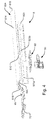
- the screening arrangement comprises a screening body 6, a top element 4 and a bottom element 7, between which the screening body 6 extends as illustrated in Fig. 1 .
- Fig. 2 the window frame is shown with parts removed, so that only the right-hand side rail 9 is present, which illustration is only shown for practical explanation of details of the cord adjustment unit in the following. Reference however will be made to both the left-hand side rail 8 and the right-hand side rail 9.
- the screening arrangement 1 comprises a screening body 6 and two side rails 8, 9 each defining a longitudinal direction between a lower end 818 and an upper end 819 and having a predefined length corresponding to a first installation position, the side rails 8, 9 each being configured to form a break-off section 8a and a remaining section 8b for providing at least one adjusted length corresponding to a respective at least one other installation position, the adjusted length being shorter than the length of the side rail 8, 9 in the first installation position, the screening arrangement further comprising at least one cord system having a cord (not shown) for guiding the screening body between a screening position and a non-screening position.
- the cord system further comprises a cord adjustment means 10, 20, 30, 40 intended to be connected to at least a part of the frame 2 and/or the side rail 8, 9 and having a tortuous path 222, the tortuous path 222 having a predefined length corresponding to the length of the break-off section (8a) for providing an adjusted length of the cord 410 in the at least one other installation position.
- the cord adjustment means includes a cord adjustment unit 10 having a receiving fitting 30 and a cord holder 40, configured to hold the cord 410, the receiving fitting 30 in the mounted condition furthermore being configured to be connected to a cord adjustment member 20 comprising the tortuous path 222.
- the receiving fitting 30 is arranged to be connected to the frame 2 and the side rail 8, and a cord adjustment member 20 which is configured to receive the cord holder 40, the cord adjustment member having a tortuous path 222 for providing at least one adjusted length of the cord 410 corresponding to the at least one adjusted length of the at least one other installation position, the cord adjustment member 20 in the mounted condition being connected to the receiving fitting 30.
- connection to should in the present context not be construed as limited to a physical connection in the form of fittings or equivalent means holding parts together in proximity. It should merely be understood as the parts being positioned in the installation position adjacent to or in the vicinity to each other in such as way that they may interact with each other according to the intended purpose, e.g. the cord adjustment unit is connected to the side rail in such as way that the cord may be provided from the cord adjusting unit to the track of the side rail.
- Ways to connect parts and/or mount parts to each other may include gluing, screwing or for example welding.
- each side rail 8, 9 includes at least one weakening portion 810 such that a break-off section 8a and a remaining section 8b are formed of the side rail 8 best illustrated in Fig. 4 , and the length of the remaining section 8b corresponds to the at least one other installation position so that the length of the tortuous path corresponds to the length of the break-off section 8a.
- the predefined length of the break-off section 8a to be broken off in a second installation position defines the length of the tortuous path, i.e. the length that the cord should be adjusted to for fitting the at least one other installation position.
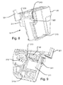
- the cord adjustment unit 10 is provided with a tortuous path, which cannot be adjusted in the mounted condition, i.e. the length of the cord is maintained. Accordingly, the cord holder 40 is configured to be connected to a first slit 230 in the cord adjustment member 20 and to a second slit 320 in the receiving fitting 30 as illustrated in Figs 10 and 11 . In this way the first and second slits 230, 320 in the mounted condition faces each other so that the cord holder 40 in the at least one other installation position is accommodated in the first and second slits 230, 320, the slits 230, 320 substantially has a shape corresponding to the shape of the cord holder 40.
- the cord is supplied in a length corresponding to the unadjusted length of the side rail, and is guided along the tortuous path to provide a shortened effective length.
- the invention may also be applicable to such cases, in which the side rail is able to be elongated, for instance by means of an extension.
- the cord may be supplied guided along the tortuous path and the released to attain a longer effective length. Guiding the cord along a second, shorter tortuous path is also conceivable as an alternative.
- the shape of the cord holder 40 is substantially T-shaped.
- other suitable geometrical shapes could be used as long as the slits 230, 240 of the receiving fitting 20 and the cord adjustment member are able to accommodate the cord holder in the provided shape.
- the cord 410 is embedded in the material of the cord holder 40 so that only one free end of the cord 410 is present. It is also important that the shape of the cord holder 40 facilitates maintaining the cord holder 40 fixed in the slits 230, 320.
- the tortuous path 222 is configured so that the cord 410 in the installation position is wound up in the cord adjustment member 20.
- the tortuous path 222 runs in the cord adjustment member 20 substantially in a loop around the first slit 230 of the cord adjustment member 20.
- the tortuous path comprises a first path part 222a, a second path part 222b and a third path part 222c, illustrated in detail in Figs 6a to 6d .
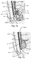
- the cord holder 40 is adapted to be engaged in the first slit 230 of the cord adjustment member 20 so that the cord 410 in the mounted condition, best illustrated in Fig. 7a , extends towards the upper end 819 of the side rail and into the first path part 222a.
- the cord From the first path part 222a the cord is to be moved along the first path part 222a in a direction towards the upper end 819 of the side rail 8. From here it is to be led to the second path part 222b so that the cord 410 extends around an end of the first slit 230, facing the upper end 819 of the side rail to the third path part 222c of the cord adjustment member 20, where the cord 410 extends towards the lower end (818) of the side rail 8. In this way the cord 410 is guided substantially in a rectangular shaped loop on a back side 211 of the cord adjustment member.
- the cord 410 is led from the third path part 222c to guiding means provided in the cord adjustment member so that the cord may be guided into the side rail.
- the cord adjustment member 20 comprises cord guiding means 225, 226, 227 for guiding the cord 410 to the side rail 8.
- cord guiding means 225, 226, 227 for guiding the cord 410 to the side rail 8.
- the cord guiding means is provided in connection with the cord adjustment member 20 so that the cord guiding means is configured as an entry groove 225 for leading the cord 410 from the third path part 222c of the tortuous path to a guiding groove 226, a guiding groove 226 leading the cord 410 to an exit groove 227 so that the cord 410 is guided into the side rail 8 in a direction towards the upper end 819 of the side rail 8.
- the tortuous path is configured to have a predetermined length ranging from about 3 to 8 cm, preferably ranging from about 4 to 7 cm and most preferably ranging from about 5 to 6 cm.
- the length of the path could be any other length suitable for adjusting a cord length to any kind of window screening arrangement dimensions.
- the side rail 8 comprises a first leg 823 adapted to be mounted on an inner side face of a side piece of a window frame and a second leg 824 extending in a general plane at an angle to the first leg and adapted to cover side edges of the screening body 6 in the mounted condition.
- at least the second leg 824 is provided with the weakening portion 810 for breaking the side rail 8 into the break-off section 8a and the remaining section 8b.
- the second leg 824 has a front side 814 and a back side 815 including a track 820 extending in the longitudinal direction.
- the first leg 823 of the side rail is provided with a first flange portion 823a extending substantially in parallel with the general plane of the second leg 824 to form a guiding track 821 for the side edges of the screening body and a second flange portion 823b at the free edge of the first flange portion 823a, and a third flange portion 823c extending substantially in parallel with the general plane of the second leg 824 at a bottom part of the first leg 823 opposite to the extension of the second leg 824.
- the receiving fitting For mounting the receiving fitting onto for example a side rail corresponding to that of the embodiment in Fig. 4 , the receiving fitting comprises, as illustrated partly in Figs 5 and 7a , a mounting side 310 intended to face a side piece of the window frame in the mounted condition and an opposite facing receiving side 311 intended to be connected with a back side 211 of the cord adjustment member 20, where the mounting side 310 has mounting means 312 for mounting the receiving fitting 30 to the side piece of the window frame and connecting means 313, 313a for connecting the receiving fitting 30 to the side rail 8 of the screening arrangement 1.
- the connecting means of the receiving fitting 30 is configured as a flange portion 313 having a groove 313a adapted to be engaged with the third flange portion 823c of the first leg 823 of the side rail 8 so that the third flange portion 823c is received in the flange portion 313.
- the groove 313a is adapted to be engaged with the third flange portion 823c of the first leg 823 by a snap or click engagement, as illustrated in Fig. 5 .
- the mounting means of the receiving fitting 30 is configured as a hole 312 arranged to receive a mounting element, such as a screw for fastening the receiving fitting to the frame side piece.
- the receiving fitting may therefore be mounted to the frame and side rail prior to connecting the receiving fitting with the cord adjustment member, thus providing an easy installation of the cord adjustment unit.
- the receiving side 311 of the receiving fitting 30 comprises first receiving means 321, 322, 323 for connecting with attachment means 241, 242, 243 provided substantially on the back side 211 of the cord adjustment member 20 as illustrated more clearly in Figs 10 to 12 .
- the first receiving means of the receiving side comprise a finger portion 321 extending substantially from the plane provided by the receiving side 311, in the mounted condition in a direction towards the back side 815 of the second leg 824 so as to be engaged with a second finger portion 241 of the cord adjustment member 20, where the second finger portion 241 in the mounted condition extend in parallel with the first flange 823a of the first leg 823.
- the receiving means of the receiving side 311 comprise a prolonged hook portion 322 extending from the receiving side 311 substantially in parallel with the first flange 823a of the first leg 823 so as to engage with a side groove 243 on a side of the cord adjustment member 20. That is the prolonged hook portion 322 forms a grip with the side groove 243 of the cord adjustment member 20.
- the receiving side 311 is provided with a protrusion 323 extending substantially in the plane of the extension of the first leg 824 so as to be engaged with a correspondingly shaped groove 242 on the cord adjustment member 20.
- This connection between the protrusion 323 and the groove 242 provides for a closure of the guiding groove 226 in the mounted condition.
- the receiving means 321, 322, 323 mentioned above are all connected with the connecting means 241, 242, 243 at the same time in a mounted condition, where the connection may be provided as a snap engagement, the user simply clicking the cord adjustment member 20 on to the receiving fitting 30 as illustrated in Fig. 7b .
- the receiving fitting 30 and the cord adjustment member 20 is thus connected through a snap or click engagement as illustrated in Fig. 7b .
- the receiving fitting 30 and the cord adjustment member 20 in the mounted condition is mounted behind the side rail so as to be hidden behind the front side 814 of the side rails 8, 9 as illustrated in Figs 1 , 3 and 7b .
- the screening arrangement may be provided with a spacer member 50 for bridging the break-off section 8a and the remaining section 8b, and a reinforcement member 60, for reinforcing the weakening portion 810 of the side rail 8 so that unintended bending is prevented.
- a spacer member 50 for bridging the break-off section 8a and the remaining section 8b
- a reinforcement member 60 for reinforcing the weakening portion 810 of the side rail 8 so that unintended bending is prevented.
- an end member and a brake device may be provided in the supply condition.
- the method furthermore comprises the steps of providing an end member 75 and connecting the end member with a free end 818 of at least the remaining section 8b of the side rail 8, and optionally connecting a brake device 65 with the end member 75.
Landscapes
- Engineering & Computer Science (AREA)
- Structural Engineering (AREA)
- Architecture (AREA)
- Civil Engineering (AREA)
- Curtains And Furnishings For Windows Or Doors (AREA)
Priority Applications (1)
| Application Number | Priority Date | Filing Date | Title |
|---|---|---|---|
| PL15181360T PL2987944T3 (pl) | 2014-08-18 | 2015-08-18 | Urządzenie zasłaniające zawierające system linkowy oraz środki do regulacji długości linki |
Applications Claiming Priority (1)
| Application Number | Priority Date | Filing Date | Title |
|---|---|---|---|
| DKPA201470493 | 2014-08-18 |
Publications (2)
| Publication Number | Publication Date |
|---|---|
| EP2987944A1 true EP2987944A1 (de) | 2016-02-24 |
| EP2987944B1 EP2987944B1 (de) | 2018-05-02 |
Family
ID=54035126
Family Applications (1)
| Application Number | Title | Priority Date | Filing Date |
|---|---|---|---|
| EP15181360.7A Active EP2987944B1 (de) | 2014-08-18 | 2015-08-18 | Abschirmung mit einem schnursystem und einer vorrichtung zur einstellung der schnurlänge |
Country Status (2)
| Country | Link |
|---|---|
| EP (1) | EP2987944B1 (de) |
| PL (1) | PL2987944T3 (de) |
Cited By (1)
| Publication number | Priority date | Publication date | Assignee | Title |
|---|---|---|---|---|
| EP4717871A1 (de) * | 2024-09-25 | 2026-04-01 | VKR Holding A/S | Externe abschirmanordnung mit einem rückführelement und verfahren zur montage und demontage einer externen abschirmanordnung |
Citations (2)
| Publication number | Priority date | Publication date | Assignee | Title |
|---|---|---|---|---|
| WO2009052822A1 (en) * | 2007-10-26 | 2009-04-30 | Vkr Holding A/S | A screening arrangement including a fitting for fixation, and method of mounting such a screening arrangement |
| EP2216485A2 (de) * | 2009-02-09 | 2010-08-11 | Blöcker Zweigniederlassung der Hunter Douglas Holding GmbH | Schnurspannvorrichtung und damit ausgerüstete Vorhanganlage |
-
2015
- 2015-08-18 PL PL15181360T patent/PL2987944T3/pl unknown
- 2015-08-18 EP EP15181360.7A patent/EP2987944B1/de active Active
Patent Citations (2)
| Publication number | Priority date | Publication date | Assignee | Title |
|---|---|---|---|---|
| WO2009052822A1 (en) * | 2007-10-26 | 2009-04-30 | Vkr Holding A/S | A screening arrangement including a fitting for fixation, and method of mounting such a screening arrangement |
| EP2216485A2 (de) * | 2009-02-09 | 2010-08-11 | Blöcker Zweigniederlassung der Hunter Douglas Holding GmbH | Schnurspannvorrichtung und damit ausgerüstete Vorhanganlage |
Cited By (1)
| Publication number | Priority date | Publication date | Assignee | Title |
|---|---|---|---|---|
| EP4717871A1 (de) * | 2024-09-25 | 2026-04-01 | VKR Holding A/S | Externe abschirmanordnung mit einem rückführelement und verfahren zur montage und demontage einer externen abschirmanordnung |
Also Published As
| Publication number | Publication date |
|---|---|
| EP2987944B1 (de) | 2018-05-02 |
| PL2987944T3 (pl) | 2018-09-28 |
Similar Documents
| Publication | Publication Date | Title |
|---|---|---|
| JP5952970B2 (ja) | 引戸クローザーセット | |
| RU138236U1 (ru) | Устройство дверей | |
| KR101361064B1 (ko) | 방충망 고정용 프레임 조립체 | |
| CN107923223B (zh) | 用于扇叶门的手指保护装置 | |
| US20130306255A1 (en) | Roller Tube Having Fabric Attachment Channel | |
| WO2007062623A1 (de) | Haltevorrichtung für eine lichtschranke sowie verwendungen derselben | |
| EP2987944B1 (de) | Abschirmung mit einem schnursystem und einer vorrichtung zur einstellung der schnurlänge | |
| JP6247227B2 (ja) | 開閉体開閉装置 | |
| US9462908B2 (en) | Window covering fastener particularly suitable for arched coverings | |
| JP6301077B2 (ja) | 障子保持部材、及び、建具 | |
| CN111032987A (zh) | 手指保护设备 | |
| EP3330476B1 (de) | Spannseilmontage | |
| KR200459938Y1 (ko) | 방충망 고정장치 | |
| KR20200114953A (ko) | 슬라이딩 높이 조절 창 | |
| EP3124735B1 (de) | Gefaltete insektengittervorrichtung sowie verfahren zu deren befestigung | |
| EP4077861B1 (de) | Rollschirm mit einer reihe von verbindungselementen | |
| JP4160551B2 (ja) | 網戸枠の取付構造 | |
| KR20120005887U (ko) | 도어 힌지 조립체 및 이를 구비한 캐비닛 | |
| JP6216648B2 (ja) | スクリーン装置 | |
| EP3385492B1 (de) | Schnurhalterung | |
| KR101995627B1 (ko) | 창호 또는 방충망의 이탈 방지용 브래킷 | |
| EP2987943B1 (de) | Abschirmungsanordnung mit längenverstellbaren seitenschienen und verfahren zur montage dieser abschirmungsanordnung | |
| GB2498926A (en) | Restrictor assembly for a friction stay hinge | |
| KR200395376Y1 (ko) | 환기구 마감재 | |
| KR20150105147A (ko) | 방충망 장치 |
Legal Events
| Date | Code | Title | Description |
|---|---|---|---|
| PUAI | Public reference made under article 153(3) epc to a published international application that has entered the european phase |
Free format text: ORIGINAL CODE: 0009012 |
|
| AK | Designated contracting states |
Kind code of ref document: A1 Designated state(s): AL AT BE BG CH CY CZ DE DK EE ES FI FR GB GR HR HU IE IS IT LI LT LU LV MC MK MT NL NO PL PT RO RS SE SI SK SM TR |
|
| AX | Request for extension of the european patent |
Extension state: BA ME |
|
| 17P | Request for examination filed |
Effective date: 20160824 |
|
| RBV | Designated contracting states (corrected) |
Designated state(s): AL AT BE BG CH CY CZ DE DK EE ES FI FR GB GR HR HU IE IS IT LI LT LU LV MC MK MT NL NO PL PT RO RS SE SI SK SM TR |
|
| GRAP | Despatch of communication of intention to grant a patent |
Free format text: ORIGINAL CODE: EPIDOSNIGR1 |
|
| RIC1 | Information provided on ipc code assigned before grant |
Ipc: E06B 9/58 20060101AFI20171030BHEP |
|
| INTG | Intention to grant announced |
Effective date: 20171129 |
|
| GRAS | Grant fee paid |
Free format text: ORIGINAL CODE: EPIDOSNIGR3 |
|
| GRAA | (expected) grant |
Free format text: ORIGINAL CODE: 0009210 |
|
| AK | Designated contracting states |
Kind code of ref document: B1 Designated state(s): AL AT BE BG CH CY CZ DE DK EE ES FI FR GB GR HR HU IE IS IT LI LT LU LV MC MK MT NL NO PL PT RO RS SE SI SK SM TR |
|
| REG | Reference to a national code |
Ref country code: GB Ref legal event code: FG4D |
|
| REG | Reference to a national code |
Ref country code: AT Ref legal event code: REF Ref document number: 995443 Country of ref document: AT Kind code of ref document: T Effective date: 20180515 Ref country code: CH Ref legal event code: EP |
|
| REG | Reference to a national code |
Ref country code: DE Ref legal event code: R096 Ref document number: 602015010614 Country of ref document: DE |
|
| REG | Reference to a national code |
Ref country code: IE Ref legal event code: FG4D |
|
| REG | Reference to a national code |
Ref country code: FR Ref legal event code: PLFP Year of fee payment: 4 |
|
| REG | Reference to a national code |
Ref country code: NL Ref legal event code: FP |
|
| REG | Reference to a national code |
Ref country code: LT Ref legal event code: MG4D |
|
| PG25 | Lapsed in a contracting state [announced via postgrant information from national office to epo] |
Ref country code: SE Free format text: LAPSE BECAUSE OF FAILURE TO SUBMIT A TRANSLATION OF THE DESCRIPTION OR TO PAY THE FEE WITHIN THE PRESCRIBED TIME-LIMIT Effective date: 20180502 Ref country code: BG Free format text: LAPSE BECAUSE OF FAILURE TO SUBMIT A TRANSLATION OF THE DESCRIPTION OR TO PAY THE FEE WITHIN THE PRESCRIBED TIME-LIMIT Effective date: 20180802 Ref country code: NO Free format text: LAPSE BECAUSE OF FAILURE TO SUBMIT A TRANSLATION OF THE DESCRIPTION OR TO PAY THE FEE WITHIN THE PRESCRIBED TIME-LIMIT Effective date: 20180802 Ref country code: FI Free format text: LAPSE BECAUSE OF FAILURE TO SUBMIT A TRANSLATION OF THE DESCRIPTION OR TO PAY THE FEE WITHIN THE PRESCRIBED TIME-LIMIT Effective date: 20180502 Ref country code: LT Free format text: LAPSE BECAUSE OF FAILURE TO SUBMIT A TRANSLATION OF THE DESCRIPTION OR TO PAY THE FEE WITHIN THE PRESCRIBED TIME-LIMIT Effective date: 20180502 Ref country code: ES Free format text: LAPSE BECAUSE OF FAILURE TO SUBMIT A TRANSLATION OF THE DESCRIPTION OR TO PAY THE FEE WITHIN THE PRESCRIBED TIME-LIMIT Effective date: 20180502 |
|
| PG25 | Lapsed in a contracting state [announced via postgrant information from national office to epo] |
Ref country code: LV Free format text: LAPSE BECAUSE OF FAILURE TO SUBMIT A TRANSLATION OF THE DESCRIPTION OR TO PAY THE FEE WITHIN THE PRESCRIBED TIME-LIMIT Effective date: 20180502 Ref country code: HR Free format text: LAPSE BECAUSE OF FAILURE TO SUBMIT A TRANSLATION OF THE DESCRIPTION OR TO PAY THE FEE WITHIN THE PRESCRIBED TIME-LIMIT Effective date: 20180502 Ref country code: GR Free format text: LAPSE BECAUSE OF FAILURE TO SUBMIT A TRANSLATION OF THE DESCRIPTION OR TO PAY THE FEE WITHIN THE PRESCRIBED TIME-LIMIT Effective date: 20180803 Ref country code: RS Free format text: LAPSE BECAUSE OF FAILURE TO SUBMIT A TRANSLATION OF THE DESCRIPTION OR TO PAY THE FEE WITHIN THE PRESCRIBED TIME-LIMIT Effective date: 20180502 |
|
| REG | Reference to a national code |
Ref country code: AT Ref legal event code: MK05 Ref document number: 995443 Country of ref document: AT Kind code of ref document: T Effective date: 20180502 |
|
| PG25 | Lapsed in a contracting state [announced via postgrant information from national office to epo] |
Ref country code: AT Free format text: LAPSE BECAUSE OF FAILURE TO SUBMIT A TRANSLATION OF THE DESCRIPTION OR TO PAY THE FEE WITHIN THE PRESCRIBED TIME-LIMIT Effective date: 20180502 Ref country code: EE Free format text: LAPSE BECAUSE OF FAILURE TO SUBMIT A TRANSLATION OF THE DESCRIPTION OR TO PAY THE FEE WITHIN THE PRESCRIBED TIME-LIMIT Effective date: 20180502 Ref country code: DK Free format text: LAPSE BECAUSE OF FAILURE TO SUBMIT A TRANSLATION OF THE DESCRIPTION OR TO PAY THE FEE WITHIN THE PRESCRIBED TIME-LIMIT Effective date: 20180502 Ref country code: CZ Free format text: LAPSE BECAUSE OF FAILURE TO SUBMIT A TRANSLATION OF THE DESCRIPTION OR TO PAY THE FEE WITHIN THE PRESCRIBED TIME-LIMIT Effective date: 20180502 Ref country code: RO Free format text: LAPSE BECAUSE OF FAILURE TO SUBMIT A TRANSLATION OF THE DESCRIPTION OR TO PAY THE FEE WITHIN THE PRESCRIBED TIME-LIMIT Effective date: 20180502 Ref country code: SK Free format text: LAPSE BECAUSE OF FAILURE TO SUBMIT A TRANSLATION OF THE DESCRIPTION OR TO PAY THE FEE WITHIN THE PRESCRIBED TIME-LIMIT Effective date: 20180502 |
|
| REG | Reference to a national code |
Ref country code: DE Ref legal event code: R097 Ref document number: 602015010614 Country of ref document: DE |
|
| PG25 | Lapsed in a contracting state [announced via postgrant information from national office to epo] |
Ref country code: IT Free format text: LAPSE BECAUSE OF FAILURE TO SUBMIT A TRANSLATION OF THE DESCRIPTION OR TO PAY THE FEE WITHIN THE PRESCRIBED TIME-LIMIT Effective date: 20180502 Ref country code: SM Free format text: LAPSE BECAUSE OF FAILURE TO SUBMIT A TRANSLATION OF THE DESCRIPTION OR TO PAY THE FEE WITHIN THE PRESCRIBED TIME-LIMIT Effective date: 20180502 |
|
| PLBE | No opposition filed within time limit |
Free format text: ORIGINAL CODE: 0009261 |
|
| STAA | Information on the status of an ep patent application or granted ep patent |
Free format text: STATUS: NO OPPOSITION FILED WITHIN TIME LIMIT |
|
| PG25 | Lapsed in a contracting state [announced via postgrant information from national office to epo] |
Ref country code: MC Free format text: LAPSE BECAUSE OF FAILURE TO SUBMIT A TRANSLATION OF THE DESCRIPTION OR TO PAY THE FEE WITHIN THE PRESCRIBED TIME-LIMIT Effective date: 20180502 |
|
| REG | Reference to a national code |
Ref country code: CH Ref legal event code: PL |
|
| 26N | No opposition filed |
Effective date: 20190205 |
|
| PG25 | Lapsed in a contracting state [announced via postgrant information from national office to epo] |
Ref country code: LI Free format text: LAPSE BECAUSE OF NON-PAYMENT OF DUE FEES Effective date: 20180831 Ref country code: LU Free format text: LAPSE BECAUSE OF NON-PAYMENT OF DUE FEES Effective date: 20180818 Ref country code: CH Free format text: LAPSE BECAUSE OF NON-PAYMENT OF DUE FEES Effective date: 20180831 |
|
| REG | Reference to a national code |
Ref country code: BE Ref legal event code: MM Effective date: 20180831 |
|
| REG | Reference to a national code |
Ref country code: IE Ref legal event code: MM4A |
|
| PG25 | Lapsed in a contracting state [announced via postgrant information from national office to epo] |
Ref country code: SI Free format text: LAPSE BECAUSE OF FAILURE TO SUBMIT A TRANSLATION OF THE DESCRIPTION OR TO PAY THE FEE WITHIN THE PRESCRIBED TIME-LIMIT Effective date: 20180502 |
|
| PG25 | Lapsed in a contracting state [announced via postgrant information from national office to epo] |
Ref country code: IE Free format text: LAPSE BECAUSE OF NON-PAYMENT OF DUE FEES Effective date: 20180818 |
|
| PG25 | Lapsed in a contracting state [announced via postgrant information from national office to epo] |
Ref country code: BE Free format text: LAPSE BECAUSE OF NON-PAYMENT OF DUE FEES Effective date: 20180831 |
|
| PG25 | Lapsed in a contracting state [announced via postgrant information from national office to epo] |
Ref country code: AL Free format text: LAPSE BECAUSE OF FAILURE TO SUBMIT A TRANSLATION OF THE DESCRIPTION OR TO PAY THE FEE WITHIN THE PRESCRIBED TIME-LIMIT Effective date: 20180502 |
|
| PG25 | Lapsed in a contracting state [announced via postgrant information from national office to epo] |
Ref country code: MT Free format text: LAPSE BECAUSE OF NON-PAYMENT OF DUE FEES Effective date: 20180818 |
|
| PG25 | Lapsed in a contracting state [announced via postgrant information from national office to epo] |
Ref country code: TR Free format text: LAPSE BECAUSE OF FAILURE TO SUBMIT A TRANSLATION OF THE DESCRIPTION OR TO PAY THE FEE WITHIN THE PRESCRIBED TIME-LIMIT Effective date: 20180502 |
|
| PG25 | Lapsed in a contracting state [announced via postgrant information from national office to epo] |
Ref country code: PT Free format text: LAPSE BECAUSE OF FAILURE TO SUBMIT A TRANSLATION OF THE DESCRIPTION OR TO PAY THE FEE WITHIN THE PRESCRIBED TIME-LIMIT Effective date: 20180502 |
|
| PG25 | Lapsed in a contracting state [announced via postgrant information from national office to epo] |
Ref country code: MK Free format text: LAPSE BECAUSE OF NON-PAYMENT OF DUE FEES Effective date: 20180502 Ref country code: CY Free format text: LAPSE BECAUSE OF FAILURE TO SUBMIT A TRANSLATION OF THE DESCRIPTION OR TO PAY THE FEE WITHIN THE PRESCRIBED TIME-LIMIT Effective date: 20180502 Ref country code: HU Free format text: LAPSE BECAUSE OF FAILURE TO SUBMIT A TRANSLATION OF THE DESCRIPTION OR TO PAY THE FEE WITHIN THE PRESCRIBED TIME-LIMIT; INVALID AB INITIO Effective date: 20150818 |
|
| PG25 | Lapsed in a contracting state [announced via postgrant information from national office to epo] |
Ref country code: IS Free format text: LAPSE BECAUSE OF FAILURE TO SUBMIT A TRANSLATION OF THE DESCRIPTION OR TO PAY THE FEE WITHIN THE PRESCRIBED TIME-LIMIT Effective date: 20180902 |
|
| PGFP | Annual fee paid to national office [announced via postgrant information from national office to epo] |
Ref country code: NL Payment date: 20230719 Year of fee payment: 9 |
|
| REG | Reference to a national code |
Ref country code: NL Ref legal event code: MM Effective date: 20240901 |
|
| PG25 | Lapsed in a contracting state [announced via postgrant information from national office to epo] |
Ref country code: NL Free format text: LAPSE BECAUSE OF NON-PAYMENT OF DUE FEES Effective date: 20240901 |
|
| PGFP | Annual fee paid to national office [announced via postgrant information from national office to epo] |
Ref country code: DE Payment date: 20250702 Year of fee payment: 11 |
|
| PGFP | Annual fee paid to national office [announced via postgrant information from national office to epo] |
Ref country code: PL Payment date: 20250714 Year of fee payment: 11 |
|
| PGFP | Annual fee paid to national office [announced via postgrant information from national office to epo] |
Ref country code: GB Payment date: 20250703 Year of fee payment: 11 |
|
| PGFP | Annual fee paid to national office [announced via postgrant information from national office to epo] |
Ref country code: FR Payment date: 20250721 Year of fee payment: 11 |