EP2987961B1 - Gasturbinenmotorsystem sowie dazugehöriges verfahren - Google Patents
Gasturbinenmotorsystem sowie dazugehöriges verfahren Download PDFInfo
- Publication number
- EP2987961B1 EP2987961B1 EP15181010.8A EP15181010A EP2987961B1 EP 2987961 B1 EP2987961 B1 EP 2987961B1 EP 15181010 A EP15181010 A EP 15181010A EP 2987961 B1 EP2987961 B1 EP 2987961B1
- Authority
- EP
- European Patent Office
- Prior art keywords
- turbine engine
- clutch
- electric machine
- gas turbine
- fuel pump
- Prior art date
- Legal status (The legal status is an assumption and is not a legal conclusion. Google has not performed a legal analysis and makes no representation as to the accuracy of the status listed.)
- Active
Links
Images


Classifications
-
- F—MECHANICAL ENGINEERING; LIGHTING; HEATING; WEAPONS; BLASTING
- F02—COMBUSTION ENGINES; HOT-GAS OR COMBUSTION-PRODUCT ENGINE PLANTS
- F02C—GAS-TURBINE PLANTS; AIR INTAKES FOR JET-PROPULSION PLANTS; CONTROLLING FUEL SUPPLY IN AIR-BREATHING JET-PROPULSION PLANTS
- F02C7/00—Features, components parts, details or accessories, not provided for in, or of interest apart form groups F02C1/00 - F02C6/00; Air intakes for jet-propulsion plants
- F02C7/32—Arrangement, mounting, or driving, of auxiliaries
-
- F—MECHANICAL ENGINEERING; LIGHTING; HEATING; WEAPONS; BLASTING
- F01—MACHINES OR ENGINES IN GENERAL; ENGINE PLANTS IN GENERAL; STEAM ENGINES
- F01D—NON-POSITIVE DISPLACEMENT MACHINES OR ENGINES, e.g. STEAM TURBINES
- F01D15/00—Adaptations of machines or engines for special use; Combinations of engines with devices driven thereby
- F01D15/10—Adaptations for driving, or combinations with, electric generators
-
- F—MECHANICAL ENGINEERING; LIGHTING; HEATING; WEAPONS; BLASTING
- F02—COMBUSTION ENGINES; HOT-GAS OR COMBUSTION-PRODUCT ENGINE PLANTS
- F02C—GAS-TURBINE PLANTS; AIR INTAKES FOR JET-PROPULSION PLANTS; CONTROLLING FUEL SUPPLY IN AIR-BREATHING JET-PROPULSION PLANTS
- F02C3/00—Gas-turbine plants characterised by the use of combustion products as the working fluid
- F02C3/04—Gas-turbine plants characterised by the use of combustion products as the working fluid having a turbine driving a compressor
- F02C3/107—Gas-turbine plants characterised by the use of combustion products as the working fluid having a turbine driving a compressor with two or more rotors connected by power transmission
-
- F—MECHANICAL ENGINEERING; LIGHTING; HEATING; WEAPONS; BLASTING
- F02—COMBUSTION ENGINES; HOT-GAS OR COMBUSTION-PRODUCT ENGINE PLANTS
- F02C—GAS-TURBINE PLANTS; AIR INTAKES FOR JET-PROPULSION PLANTS; CONTROLLING FUEL SUPPLY IN AIR-BREATHING JET-PROPULSION PLANTS
- F02C6/00—Plural gas-turbine plants; Combinations of gas-turbine plants with other apparatus; Adaptations of gas-turbine plants for special use
- F02C6/20—Adaptations of gas-turbine plants for driving vehicles
-
- F—MECHANICAL ENGINEERING; LIGHTING; HEATING; WEAPONS; BLASTING
- F02—COMBUSTION ENGINES; HOT-GAS OR COMBUSTION-PRODUCT ENGINE PLANTS
- F02C—GAS-TURBINE PLANTS; AIR INTAKES FOR JET-PROPULSION PLANTS; CONTROLLING FUEL SUPPLY IN AIR-BREATHING JET-PROPULSION PLANTS
- F02C7/00—Features, components parts, details or accessories, not provided for in, or of interest apart form groups F02C1/00 - F02C6/00; Air intakes for jet-propulsion plants
- F02C7/22—Fuel supply systems
-
- F—MECHANICAL ENGINEERING; LIGHTING; HEATING; WEAPONS; BLASTING
- F02—COMBUSTION ENGINES; HOT-GAS OR COMBUSTION-PRODUCT ENGINE PLANTS
- F02C—GAS-TURBINE PLANTS; AIR INTAKES FOR JET-PROPULSION PLANTS; CONTROLLING FUEL SUPPLY IN AIR-BREATHING JET-PROPULSION PLANTS
- F02C9/00—Controlling gas-turbine plants; Controlling fuel supply in air- breathing jet-propulsion plants
- F02C9/26—Control of fuel supply
- F02C9/28—Regulating systems responsive to plant or ambient parameters, e.g. temperature, pressure, rotor speed
-
- F—MECHANICAL ENGINEERING; LIGHTING; HEATING; WEAPONS; BLASTING
- F05—INDEXING SCHEMES RELATING TO ENGINES OR PUMPS IN VARIOUS SUBCLASSES OF CLASSES F01-F04
- F05D—INDEXING SCHEME FOR ASPECTS RELATING TO NON-POSITIVE-DISPLACEMENT MACHINES OR ENGINES, GAS-TURBINES OR JET-PROPULSION PLANTS
- F05D2220/00—Application
- F05D2220/30—Application in turbines
- F05D2220/32—Application in turbines in gas turbines
- F05D2220/323—Application in turbines in gas turbines for aircraft propulsion, e.g. jet engines
-
- F—MECHANICAL ENGINEERING; LIGHTING; HEATING; WEAPONS; BLASTING
- F05—INDEXING SCHEMES RELATING TO ENGINES OR PUMPS IN VARIOUS SUBCLASSES OF CLASSES F01-F04
- F05D—INDEXING SCHEME FOR ASPECTS RELATING TO NON-POSITIVE-DISPLACEMENT MACHINES OR ENGINES, GAS-TURBINES OR JET-PROPULSION PLANTS
- F05D2260/00—Function
- F05D2260/40—Transmission of power
- F05D2260/402—Transmission of power through friction drives
- F05D2260/4023—Transmission of power through friction drives through a friction clutch
-
- F—MECHANICAL ENGINEERING; LIGHTING; HEATING; WEAPONS; BLASTING
- F05—INDEXING SCHEMES RELATING TO ENGINES OR PUMPS IN VARIOUS SUBCLASSES OF CLASSES F01-F04
- F05D—INDEXING SCHEME FOR ASPECTS RELATING TO NON-POSITIVE-DISPLACEMENT MACHINES OR ENGINES, GAS-TURBINES OR JET-PROPULSION PLANTS
- F05D2260/00—Function
- F05D2260/42—Storage of energy
-
- F—MECHANICAL ENGINEERING; LIGHTING; HEATING; WEAPONS; BLASTING
- F05—INDEXING SCHEMES RELATING TO ENGINES OR PUMPS IN VARIOUS SUBCLASSES OF CLASSES F01-F04
- F05D—INDEXING SCHEME FOR ASPECTS RELATING TO NON-POSITIVE-DISPLACEMENT MACHINES OR ENGINES, GAS-TURBINES OR JET-PROPULSION PLANTS
- F05D2260/00—Function
- F05D2260/84—Redundancy
-
- F—MECHANICAL ENGINEERING; LIGHTING; HEATING; WEAPONS; BLASTING
- F05—INDEXING SCHEMES RELATING TO ENGINES OR PUMPS IN VARIOUS SUBCLASSES OF CLASSES F01-F04
- F05D—INDEXING SCHEME FOR ASPECTS RELATING TO NON-POSITIVE-DISPLACEMENT MACHINES OR ENGINES, GAS-TURBINES OR JET-PROPULSION PLANTS
- F05D2270/00—Control
- F05D2270/01—Purpose of the control system
- F05D2270/05—Purpose of the control system to affect the output of the engine
-
- F—MECHANICAL ENGINEERING; LIGHTING; HEATING; WEAPONS; BLASTING
- F05—INDEXING SCHEMES RELATING TO ENGINES OR PUMPS IN VARIOUS SUBCLASSES OF CLASSES F01-F04
- F05D—INDEXING SCHEME FOR ASPECTS RELATING TO NON-POSITIVE-DISPLACEMENT MACHINES OR ENGINES, GAS-TURBINES OR JET-PROPULSION PLANTS
- F05D2270/00—Control
- F05D2270/30—Control parameters, e.g. input parameters
- F05D2270/335—Output power or torque
Definitions
- the present disclosure relates generally to gas turbine engines for aerospace applications. More specifically, the present disclosure relates to the use of electric machines for power distribution in aerospace applications of gas turbine engines.
- Gas turbine engines are used to power aircraft, watercraft, power generators, and the like.
- Gas turbine engines typically include one or more compressors, a combustor, and one or more turbines.
- a fan or propeller is used to draw air into the engine and feeds the drawn-in air to the gas turbine core.
- the compressor includes alternating stages of rotating blades and static vanes, which increase the pressure of the drawn-in air as it travels through the gas turbine core. The compressor thus outputs higher-pressure air, which it delivers to the combustor.
- a fuel pump supplies pressurized fuel (such as kerosene) to the combustor, typically via one or more fuel injectors.
- the fuel is mixed with the higher-pressure air and is ignited by an igniter.
- the products of the combustion reaction that occurs in the combustor e.g., hot gas
- the turbine is typically made up of an assembly of discs with blades, which are attached to turbine shafts, nozzle guide vanes, casings, and other structures.
- the turbine converts the thermal energy supplied by the combustion products into kinetic energy.
- the work extracted from the combustion products by the turbine may be used to drive the fan, the compressor, and, sometimes, an output shaft. Leftover products of the combustion are exhausted out of the engine and may provide thrust in some configurations.
- Aerospace applications of gas turbine engines include turboshaft, turboprop, and turbofan engines.
- the gas turbine engine provides thrust to propel the aircraft, and also supplies power for engine accessories and aircraft accessories.
- Typical engine accessories include an engine control unit, a starter, fuel pumps, oil pumps, etc.
- Typical aircraft accessories include hydraulic pumps and electric generators to supply hydraulic and/or electrical power to the aircraft cabin and/or aircraft electrical systems.
- the gas turbine engine provides thrust via the main engine shafting, which is driven by the turbine as a result of the combustion reaction.
- the gas turbine engine also powers engine accessories and aircraft accessories by one or more accessory drives, as further explained below.
- Some gas turbine engines also output bleed air, which is compressed air produced by the compressor but not delivered to the combustor. Bleed air can be used by the engine to, for example, generate propulsion thrust, drive a pneumatic actuator or provide engine cooling, or may be supplied to the aircraft for cabin pressurization or other purposes.
- a central shaft typically links the turbine and compressor sections of the turbine engine.
- a high pressure shaft may link a high pressure compressor with a high pressure turbine, while a low pressure shaft links the fan with a low pressure turbine.
- the low pressure shaft may be concentric with and disposed within the high pressure shaft.
- one or more mechanical or electrical "accessory” drives transmit power from the engine mainline shafts to the engine and aircraft accessories.
- a bevel gear alone or in combination with other components (such as a stub shaft, idler, spur gears and splines), may be driven by a mainline shaft.
- the bevel gear may drive an accessory gearbox, which in turn runs the engine accessories and/or aircraft accessories.
- an accessory drive can be used "in reverse" to transmit power from a starter to the engine.
- Classic "power take-off" systems include mechanical drives that transmit power from the gears mounted on the engine mainline shafts to an accessory gearbox to drive accessories such as pumps and generators.
- the conventional accessory gearbox can be replaced by "more electric” systems that have embedded electrical starter/motor/generators mounted directly on the engine mainline shafts.
- Power electronics can convert the variable frequency electrical power that the engine delivers into alternating current (AC) or direct current (DC) as need by the engine and aircraft accessories.
- FR2983248 describes an aircraft turbo machine comprising a turbine shaft and a pump module comprising a pump shaft connected to the turbine shaft.
- a fuel supply of the engine is adapted to deliver a fuel flow according to the speed of rotation of the turbine shaft and an electrical device is adapted in a first mode of operation, for driving said pump shaft in rotation to operate a feed pump and, in a second mode of operation, to be rotated by the pump shaft to electrically supply equipment.
- DE3502578 describes an auxiliary power unit for at least one gas-turbine engine.
- GB988817 describes a gas turbine engine having a combustion chamber, an air compressor and a fuel pump both supplying said chamber, an air compressor and a fuel pump both supplying said chamber, an electric motor being arranged to drive the compressor and pump until the engine becomes self-driving, and to drive thereafter the fuel pump without driving the air compressor.
- a gas turbine engine system 100 include a gas turbine engine 110, an accessory subsystem 300, and a control unit 154.
- a clutch 138 selectively couples and decouples an electric machine 140 and a fuel pump 144 from a main drive (e.g., a high pressure shaft or "HPS" 120) of the turbine engine 110 via a power take-off (PTO) assembly 146.
- the illustrative PTO assembly 146 includes an accessory-driving gear 132 and an accessory gearbox 134.
- components of the accessory subsystem 300 may be embodied as a "more" electric engine rather than as a gearbox-driven power distribution system.
- the clutch 138 selectively couples and decouples the electric machine 140 and the fuel pump 144 directly from a main drive of the turbine engine 110 (e.g., HPS 120), rather than via the accessory gearbox 134. That is, whereas in the illustrative embodiments, the electric machine 140 and the fuel pump 144 are mechanically coupled to the turbine engine 110 and to one another by the power take-off assembly 146, in other embodiments, the electric machine 140 and the fuel pump 144 may be directly or electrically coupled to a main drive of the turbine engine 110 (e.g., HPS 120), using more electric technology.
- a main drive of the turbine engine 110 e.g., HPS 120
- aspects of the power management techniques disclosed herein can be used in connection with conventional fuel pumps that are mechanically driven by a main drive of the turbine engine 110 (via the PTO assembly 146), and can also incorporate newer, more efficient technologies of a more electric engine and electric fuel pumps.
- the illustrative turbine engine 110 is a multi-shaft turbofan gas turbine engine configured for aerospace applications; however, aspects of the present disclosure are applicable to other types of turbine engines, including various types of turbofan and turboshaft systems, as well as turbine engines that are configured for other, non-aerospace types of applications.
- a fan 112 e.g., a fan, variable pitch propeller, etc.
- some of the air drawn into the turbine engine 110 by the fan 112 may bypass other engine components via a bypass region 126 (e.g., a bypass duct). The remaining air flows to one or more compressors 116.
- a low pressure compressor may increase the pressure of air received from the fan 112, and a high pressure compressor may further increase the pressure of air received from the low pressure compressor.
- the compressor(s) 116 increase the pressure of the drawn-in air and forward the higher-pressure air to a combustor 118.
- the pressurized air is mixed with fuel (e.g., gas), which is supplied to the combustor 118 by a fuel supply, e.g. the fuel pump 144.
- a fuel supply e.g. the fuel pump 144.
- a flow meter, flow control valve, or similar device e.g., a fuel flow sensor, FF
- An igniter (not shown) is typically used to cause the mixture of air and fuel to combust.
- the high-energy combusted air is directed to one or more turbines 122, 124.
- a high pressure turbine 122 is disposed in axial flow series with a low pressure turbine 124.
- the combusted air expands through the turbines 122, 124, causing the turbines 122, 124 to rotate.
- the combusted air is then exhausted through, for example, a propulsion nozzle (not shown), which may generate additional propulsion thrust.
- the rotation of the turbines 122, 124 causes the engine shafts 114, 120 to rotate. More specifically, rotation of the low pressure turbine 124 drives a low pressure shaft 114, which drives the fan 112. Rotation of the high pressure turbine 122 drives the high pressure shaft 120, which drives the compressor(s) 116.
- the shafts 114, 120 are concentrically disposed and independently rotatable. In other embodiments, the shafts 114, 120 may be parallel but not concentric. Further, a single shaft, or more than two engine shafts, may be provided, in other embodiments. For example, an intermediate shaft may be disposed concentrically between the low pressure shaft 114 and the high pressure shaft 120 to support an intermediate-pressure compressor and turbine.
- the turbine engine 110 can supply power to drive the electric machine 140 and the fuel pump 144.
- power output by the turbine engine 110 e.g., by the illustrative turbines 122, 124
- the power take-off (“PTO") assembly 146 which is powered by the turbine-driven rotation of the high pressure shaft 120.
- the illustrative PTO assembly 146 includes the accessory-driving gear 132, which is driven by rotation of the high pressure shaft 120.
- the accessory-driving gear 132 is substantially coplanar with and intermeshes with an engine-driven gear 312 of the accessory gearbox 134.
- the PTO assembly 146 is illustratively shown as coupled to the high pressure shaft 120, it should be understood that the PTO assembly 146 may be coupled to the low pressure shaft 114, or to another engine shaft, in other embodiments of the turbine engine system 100. Alternatively, embodiments of the PTO assembly 146 may be provided on multiple different engine shafts (e.g., on both of the shafts 114, 120), in order to support an additional number of electric machines 140.
- the clutch 138 may be embodied as any suitable device that is capable of selectively coupling and decoupling two rotating shafts.
- the clutch 138 may be embodied as a friction clutch or a brake.
- the clutch 138 is configured to "fail engaged" in order to ensure that the fuel pump 144 and/or other components of the accessory subsystem 300 remain connected to the turbine engine 110 if an electrical failure occurs.
- the fuel pump 144 may be embodied as any suitable device that is capable of drawing fuel from a fuel supply (e.g., a fuel tank, not shown), and supplying pressurized fuel for delivery to the combustor 118 (e.g., by a fuel injector).
- the electric machine 140 may be embodied as an electric generator, a motor/generator, a permanent magnet alternator (PMA), or another device that can generate electrical power by converting rotational power to electrical power.
- the illustrative electric machine 140 has a "generator" mode in which the electric machine 140 supplies electrical energy 148 to an aircraft electrical system 150 or to an energy storage device 152 at various times during operation of an aircraft driven by the gas turbine engine 110.
- the aircraft electrical system 150 can include in-cabin electrical systems, such as lighting and entertainment systems.
- the energy storage device 152 may be embodied as, for example, a battery or a capacitor.
- the electric machine 140 also has a "motor" mode in which it draws electrical energy from the energy storage device 152 and converts the received electrical energy into rotational power, which is then supplied to the turbine engine 110 via the power take-off assembly 146 when the clutch 138 is engaged.
- the electric machine 140 can act as a starter for the turbine engine 110, or support high power demands by the turbine engine 110, when the clutch 138 is engaged.
- the clutch 138 can be disengaged to decouple the electric machine 140 and the fuel pump 144 from the main drive (e.g., HPS 120) of the turbine engine 110.
- the electric machine 140 and the fuel pump 144 are decoupled from the turbine engine 110, the electric machine 140 can drive the fuel pump 144.
- the fuel pump 144 can run independently of the main drive (e.g., HPS 120) of the turbine engine 110.
- operating the fuel pump 144 independently of the main drive e.g., HPS 120
- the amount of fuel that is recirculated e.g., by flowing to a spill valve and returning to the fuel tank
- the amount by which the fuel temperature may increase due to the recirculation of the fuel is reduced.
- the arrangement of the gas turbine engine system 100 disclosed herein enables the electric machine 140 to add mechanical power to the main drive (e.g., HPS 120) of the turbine engine 110 or to extract mechanical power from the turbine engine 110 in order to create electrical energy that can be used to support the engine and aircraft accessories, such as the fuel pump 144 and the aircraft electrical system 150.
- the electric machine 140 may, from time to time, store some of the created electrical energy in the energy storage device 152.
- the clutch 138 can be controlled by clutch control logic 156, executed by the control unit 154, to selectively apply the electrical energy stored in the energy storage device 152 to operation of the fuel pump 144 or to the operation of the turbine engine 110, at various different operating points in the engine's power usage profile.
- the clutch control logic 156 may engage the clutch 138 and cause the electric machine 140 to operate in a motor mode, so that electrical power previously transferred by the electric machine 140 to the energy storage device 152 can be drawn from the energy storage device 152 by the electric machine 140 and used to deliver mechanical power to the turbine engine 110 (e.g., via the PTO assembly 146 and the HPS 120).
- Use of the electric machine 140 in this way can reduce the overall stress profile of the turbine engine 110 and extend engine life.
- the illustrative control unit 154 is embodied as an electronic controller, processor, or control circuitry. In some embodiments, the control unit 154 may control the overall operation of the turbine engine 110. In other embodiments, the control unit 154 may simply control the operation of specific components of the turbine engine system 100 (such as the clutch 138 and/or the electric machine 140).
- the control unit 154 executes the clutch control logic 156 in order to control the operation of the clutch 138.
- the control unit 154 may receive data signals from a sensor (such as a pressure switch) that is coupled to the clutch 138 from time to time, and may send control signals to the clutch 138 or to an actuator that is coupled to the clutch (such as an electrohydraulic or electromechanical actuator).
- clutch data/control signals 164 These data and control signals are collectively illustrated in FIG. 1 as clutch data/control signals 164.
- the control unit 154 analyzes the data signals from the clutch 138 and signals from other components of the turbine engine system 100 (such as engine control signals 166 and sensor data signals 168 output by various engine sensors 130), and outputs control signals to selectively engage or disengage the clutch in accordance with the clutch control logic 156.
- the control unit 154 is also in electronic communication with the electric machine 140 and the fuel pump 144 to receive diagnostic signals and send control signals to these devices, although such communication links have been omitted from FIG. 1 for simplicity.
- control unit 154 may control the rate of fuel flow through the fuel pump 144 to the combustor 118 by sending electrical control signals to the fuel pump 144, and may control the operation of the electric machine 140 by sending electrical control signals to the electric machine 140.
- control unit 154 may signal the electric machine 140 to operate in "motor” or "generator” mode based on a given set of sensed operating conditions of the turbine engine system 100.
- the control unit 154 executes clutch control logic 156 to balance and smooth the application of power by the gas turbine engine system 100 over the course of an aircraft mission.
- the clutch control logic 156 may signal the clutch 138 to engage or disengage during the different operational phases (e.g., taxi, idle, takeoff, cruise, approach, thrust reverse) of the aircraft or based on current operating conditions of the aircraft.
- the control unit 154 may derive information about the current operational phase and/or the current operating conditions of the turbine engine system 100 from data signals provided by the sensors 130.
- the sensors 130 are installed at various locations on the turbine engine 110 and/or other components of the turbine engine system 100 (e.g., the clutch 138, the electric machine 140, and the fuel pump 144), and are used to sense and/or measure various physical parameters such as temperature (T), shaft speed (SS), air pressure (P), and fuel flow (FF) during operation of the turbine engine system 100.
- T temperature
- SS shaft speed
- P air pressure
- FF fuel flow
- the clutch control logic 156 is embodied as electrical circuitry or as a processor-executable component, such as a computer program, module or set of machine-executable instructions embodied in non-transitory machine-readable storage media.
- the illustrative clutch control logic 156 controls the clutch 138 to provide a number of different modes of normal operation of the electric machine 140. In a first mode of normal operation, the clutch 138 is disengaged and the electric machine 140 powers the fuel pump 144, either electronically, acting as a generator (if the fuel pump 144 is electrically powered) or mechanically, acting as a motor (if the fuel pump 144 is mechanically driven).
- the clutch control logic 156 may cause the clutch 138 to disengage when, for example, the amount of power demanded by the turbine engine 110 is not very high.
- the clutch control logic 156 may assess the power demand by, for instance, comparing a data value representing the current power demand value to a threshold value. If the current power demand by the turbine engine 110 is less than the threshold value, the clutch control logic 156 may disengage the clutch 138 so as to decouple the electric machine 140 and the fuel pump 144 from the turbine engine 110.
- the control unit 154 may control the electric machine 140 to slow down the pump speed of the fuel pump 144, in order to conserve energy (e.g., due to fuel being pumped out of the spill valve), or for other reasons.
- the electric machine 140 can control the pump speed of the fuel pump 144 to generate enough fuel pressure so that the fuel metering valve can accurately measure the fuel flow.
- the control unit 154 can analyze sensor data signals 168 (such as a fuel flow signal from a fuel flow sensor FF 130) and issue control signals to the electric machine 140 that, for example, increase or decrease the power supplied by the electric machine 140 to the fuel pump 144.
- the electric machine 140 may draw electrical power from the energy storage device 152 and supply the electrical power to the fuel pump 144.
- the electric machine 140 may act as a starter.
- the fuel pump 144 may be powered by the turbine engine 110 (through the power take-off assembly 146) or by the electric machine 140.
- the electric machine 140 may draw electrical power from the energy storage device 152 and supply the electrical power to the turbine engine 110.
- the turbine engine 110 may power the electric machine 140, in which case the electric machine 140 can operate as a generator and may transfer electrical energy to the aircraft electrical system 150, to the fuel pump 144, and/or to the energy storage device 152.
- element 210 represents the turbine engine 110
- element 212 represents an engine oil pump
- element 214 represents the PTO assembly 146
- element 220 represents the clutch 138
- element 216 represents the electric machine 140
- element 218 represents the fuel pump 144
- element 222 represents the energy storage device 152.
- the position of the fuel pump 218 and the electric machine 216 may be reversed, in some embodiments, such that the fuel pump 218 rather than the electric machine 216 is coupled to the clutch 220.
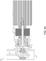
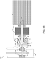
- FIGS. 3A and 3B embodiments 300A and 300B of the accessory subsystem 300 are shown, with FIG. 3A showing the clutch 138 engaged and FIG. 3B showing the clutch 138 disengaged.
- Components of the accessory subsystem 300 are housed in and supported by one or more casing structures 308, 330, 332, 338.
- the accessory-driving gear 132 intermeshes with and thereby drives the engine-driven gear 312, at 336.
- Rotation of the engine-driven gear 312 drives rotation of a PTO shaft 136.
- the driven gear 312 is fixed to and rotates with the PTO shaft 136.
- the PTO shaft 136 is supported by the casing 308, bearings 310, 314 and a fluid seal 316.
- the PTO shaft 136 is coupled to an engine-side clutch plate 318 of the clutch 138.
- a pump shaft 142 is coupled to an accessory-side clutch plate 320.
- the PTO shaft 136 and the pump shaft 142 rotate about a common axis of rotation 334.
- the electric machine 140 is supported by the pump shaft 142 and bearings 326, 328.
- the fuel pump 144 is supported by the pump shaft 142.
- the engine-side clutch plate 318 selectively engages with the accessory-side clutch plate 320 to couple the pump shaft 142 to the PTO shaft 136 and thereby cause the pump shaft 142 to rotate with the PTO shaft 136.
- the pump shaft 142 couples the electric machine 140 with the fuel pump 144.
- the electric machine 140 and the fuel pump 144 are coupled to the turbine engine 110.
- the electric machine 140 and the fuel pump 144 are decoupled from the turbine engine 110 when the clutch 138 is disengaged.
- an opposite arrangement in which the fuel pump 144 is interposed between the clutch 138 and the electric machine 140 can be implemented in other embodiments and would work equally as well.
- the electric machine 140 and the fuel pump 144 are coupled to the clutch 138 by a single shaft, the pump shaft 142.
- the electric machine 140 and the fuel pump 144 may be driven by different shafts in other embodiments.
- the pump shaft 142 may couple the fuel pump 144 to the clutch 138, and the electric machine 140 may be driven by a different shaft, which may be coupled to the pump shaft 142 by another clutch.
- a spring 322 biases the clutch 138 to the engaged position.
- the spring 322 may be embodied as a compression spring or any other biasing mechanism capable of performing the functions described herein.
- an actuator 324 can be selectively actuated by the control unit 154 to compress the spring 322 and thereby release the clutch 138.
- the actuator 324 may be embodied as any type of electronic, hydraulic, pneumatic, or force-driven actuator capable of performing the functions described herein.
- the actuator 324 may be embodied as a solenoid, a transducer, or any other mechanism that can convert energy into linear motion.
- the connection between the actuator 324 and the control unit 154 is omitted from the drawings, for simplicity.
- an illustrative process 400 that may be executed by the turbine engine system 100 (e.g., by the control unit 154) is shown. Aspects of the process 400 may be embodied as electrical circuitry, computerized programs, routines, logic and/or instructions, such as the clutch control logic 156. The illustrative process 400 can executed by the turbine engine system 100 in real time during normal operation of a turbine engine-powered vehicle or in an offline environment (e.g., during engine testing or aircraft maintenance).
- the turbine engine system 100 controls the clutch 138 to selectively couple and decouple the electric machine 140 and the fuel pump 144 from the turbine engine 110 as needed to achieve the desired operating results.
- the turbine engine system 100 may determine the current state of the clutch 138 (e.g., engaged or disengaged), compare the current state of the clutch 138 to the clutch state required by the current operating conditions or operational phase of the turbine engine 110, and then initiate a state change by the clutch 138 if there is a difference between the current clutch state and the clutch state associated with the current operating conditions or operational phase.
- the current operating conditions illustratively include the amount of power demanded by the turbine engine 110, and may also indicate a current phase of operation of the turbine engine 110 (which may be determined, for example, by turbine speed data and/or other parameters).
- the turbine engine system 100 may engage the clutch 138 to transfer electrical or mechanical power from the electric machine 140 to the turbine engine 110.
- the gas turbine engine system 100 may engage the clutch 138 to transfer mechanical power from the turbine engine 110 to the electric machine 140 and/or the fuel pump 144.
- the turbine engine system 100 may disengage the clutch 138 and use the electric machine 140 to electrically or mechanically power the fuel pump 144. To do this, the electric machine 140 may draw electrical energy 148 from the energy storage device 152 as needed. Execution of the functionality of any of the blocks 412, 414, 416 may be triggered by a determination of, or change in, the current operating conditions or operational phase of the gas turbine engine system 100.
- the turbine engine system 100 determines whether an electrical failure has occurred in the turbine engine system 100.
- the turbine engine system 100 e.g., the control unit 1514 may analyze one or more data signals received from the various components of the engine system 100 (e.g., one or more of the sensors 130). If an electrical failure has occurred, the turbine engine system 100 advances to block 420 to engage the clutch 138 as a "fail safe" measure. In this way, the clutch 138 engages to couple the electric machine 140 and the fuel pump 144 to the turbine engine 110 if an electrical failure occurs in the turbine engine system 100.
- the turbine engine system 100 advances to the end of the process 400, and the process 400 returns to block 410 to continue selectively engaging and disengaging the clutch 138 as needed in response to changes in the operating conditions and/or operational phase of the turbine engine 110.
- the illustrative control unit 154 is embodied as one or more computing devices, which may include one or more controllers or processors (e.g., microcontrollers, microprocessors, digital signal processors, field-programmable gate arrays (FPGAs), programmable logic arrays (PLAs), etc.), and/or other electrical circuitry.
- the control unit 154 includes hardware, firmware, and/or software components that are capable of performing the functions disclosed herein, including the functions of the clutch control logic 156.
- the control unit 154 may be in communication with one or more other devices (such as a server computer) by one or more communication networks (not shown), in order to perform one or more of the disclosed functions.
- the illustrative control unit 154 includes at least one processor 510, memory 512, and an input/output (I/O) subsystem 514.
- the I/O subsystem 514 typically includes, among other things, an I/O controller, a memory controller, and one or more I/O ports, although not specifically shown.
- the processor 510 and the I/O subsystem 514 are communicatively coupled to the memory 512.
- the memory 512 may be embodied as any type of suitable computer memory device (e.g., volatile memory such as various forms of random access memory).
- the I/O subsystem 514 is communicatively coupled to a number of hardware and/or software components, including a data storage device 516, communication circuitry 520, and the clutch control logic 156.
- the data storage device 516 may include one or more hard drives or other suitable persistent data storage devices (e.g., flash memory, memory cards, memory sticks, and/or others).
- Information about the different operational phases and/or operating conditions of the turbine engine 110, and/or any other data needed by the turbine engine system 100 may be stored in the data storage device 516 as engine profile data 518.
- threshold data values such as threshold levels of power demanded by the turbine engine 110, which may be used by the control unit 154 to determine the current operational phase of the gas turbine engine system 100, may be stored in the engine profile data 518.
- the engine profile data 518 may reside at least temporarily in other data storage devices of or coupled to the control unit 154 (e.g., data storage devices that are "in the cloud” or otherwise connected to the control unit 154 by a network, such as a data storage device of another computing device). Portions of the clutch control logic 156 may reside at least temporarily in the data storage device 516 and/or other data storage devices that are part of the control unit 154. Portions of the engine profile data 518 and/or clutch control logic 156 may be copied to the memory 512 during operation of the turbine engine system 100, for faster processing or other reasons.
- the clutch control logic 156 is embodied as one or more computer-executable components and/or data structures (e.g., computer hardware, software, or a combination thereof). Particular aspects of the methods and analyses that may be performed by the clutch control logic 156 may vary depending on the requirements of a particular design of the turbine engine system 100. Accordingly, the examples described herein are illustrative and intended to be non-limiting.
- the communication circuitry 520 may communicatively couple the control unit 154 to one or more other devices, systems, or communication networks, e.g., a local area network, wide area network, personal cloud, enterprise cloud, public cloud, and/or the Internet, for example. Accordingly, the communication circuitry 420 may include one or more wired or wireless network interface software, firmware, or hardware, for example, as may be needed pursuant to the specifications and/or design of the particular turbine engine system 100. Further, the control unit 154 may include other components, sub-components, and devices not illustrated herein for clarity of the description. In general, the components of the control unit 154 are communicatively coupled as shown in FIG. 5 by electronic signal paths, which may be embodied as any type of wired or wireless signal paths capable of facilitating communication between the respective devices and components.
- Embodiments in accordance with the disclosure may be implemented in hardware, firmware, software, or any combination thereof. Embodiments may also be implemented as instructions stored using one or more machine-readable media, which may be read and executed by one or more processors.
- a machine-readable medium may include any mechanism for storing or transmitting information in a form readable by a machine.
- a machine-readable medium may include any suitable form of volatile or non-volatile memory.
- Modules, data structures, and the like defined herein are defined as such for ease of discussion, and are not intended to imply that any specific implementation details are required.
- any of the described modules and/or data structures may be combined or divided into sub-modules, sub-processes or other units of computer code or data as may be required by a particular design or implementation.
- schematic elements used to represent instruction blocks or modules may be implemented using any suitable form of machine-readable instruction, and each such instruction may be implemented using any suitable programming language, library, application programming interface (API), and/or other software development tools or frameworks.
- schematic elements used to represent data or information may be implemented using any suitable electronic arrangement or data structure. Further, some connections, relationships or associations between elements may be simplified or not shown in the drawings so as not to obscure the disclosure.
Landscapes
- Engineering & Computer Science (AREA)
- Chemical & Material Sciences (AREA)
- Combustion & Propulsion (AREA)
- Mechanical Engineering (AREA)
- General Engineering & Computer Science (AREA)
- Engine Equipment That Uses Special Cycles (AREA)
Claims (14)
- Turbinenmotorsystem für ein Luftfahrzeug, wobei das Turbinenmotorsystem umfasst:einen Gasturbinenmotor (110);eine elektrische Maschine (140), welche mit dem Gasturbinenmotor gekoppelt ist;eine Kraftstoffpumpe (144), welche mit der elektrischen Maschine gekoppelt ist;eine Kupplung (138), welche konfiguriert ist, um die elektrische Maschine und die Kraftstoffpumpe selektiv mit dem Gasturbinenmotor zu koppeln und von diesem zu entkoppeln; und Steuerschaltungen (154), welche konfiguriert sind, zum: (i) Lösen der Kupplung und veranlassen, dass die elektrische Maschine (140) die Kraftstoffpumpe (144) antreibt, wenn die Kupplung gelöst ist, (ii) Eingreifen der Kupplung und veranlassen, dass die elektrische Maschine den Gasturbinenmotor (110) mit Strom versorgt, wenn die Kupplung in Eingriff steht, und (iii) Eingreifen der Kupplung und veranlassen, dass der Gasturbinenmotor die Kraftstoffpumpe und die elektrische Maschine antreibt, wenn die Kupplung in Eingriff steht.
- Turbinenmotorsystem nach Anspruch 1, umfassend ein Schaltgetriebe (134), welches mit dem Gasturbinenmotor (110) gekoppelt ist, wobei die elektrische Maschine (140) und die Kraftstoffpumpe (144) mit dem Schaltgetriebe durch die Kupplung (138) gekoppelt sind.
- Turbinenmotorsystem nach Anspruch 1, wobei die Kupplung (138) mit der elektrischen Maschine (140) und der Kraftstoffpumpe (144) gekoppelt ist.
- Turbinenmotorsystem nach Anspruch 1, wobei die Steuerschaltungen (154) mit der Gasturbinenmotor (110) und mit der Kupplung kommunizieren, und konfiguriert sind, um die Kupplung als Reaktion auf ein Datensignal zu steuern, welches von dem Gasturbinenmotor empfangen wird.
- Turbinenmotorsystem nach Anspruch 1, wobei die Steuerschaltungen (154) mit der Gasturbinenmotor (110) und mit der Kupplung kommunizieren; und wobei diese konfiguriert sind, um die Kupplung als Reaktion auf eine elektrische Störung in dem Turbinenmotorsystem einzuschalten.
- Turbinenmotorsystem nach Anspruch 1, wobei die Steuerschaltungen (154) mit der Gasturbinenmotor (110) und mit der Kupplung kommunizieren; und optional diese konfiguriert sind, um die Kupplung als Reaktion auf ein Datensignal zu lösen, welches angibt, dass ein Leistungspegel, welcher von dem Turbinenmotorsystem gefordert wird, kleiner als ein Schwellenleistungspegel ist.
- Turbinenmotorsystem nach Anspruch 1, wobei die elektrische Maschine (140) ausgebildet ist, um die Kraftstoffpumpe (144) anzutreiben, wenn die Kupplung gelöst ist.
- Turbinenmotorsystem nach Anspruch 1, wobei die elektrische Maschine (140) ausgebildet ist, um elektrische Energie von einer Energiespeichervorrichtung an den Gasturbinenmotor (110) zu übertragen, wenn die Kupplung eingeschaltet ist.
- Turbinenmotorsystem nach Anspruch 1, wobei die Kupplung, die elektrische Maschine (140) und die Kraftstoffpumpe (144) so angeordnet sind, dass die Kraftstoffpumpe (144) unabhängig von dem Gasturbinenmotor (110) betreibbar ist.
- Turbinenmotorsystem nach Anspruch 1, wobei die Steuerschaltungen (154) mit dem Gasturbinenmotor (110) und mit der Kupplung kommunizieren; und diese konfiguriert sind, um die Kupplung als Reaktion auf eine Änderung der Betriebsphase des Turbinenmotors selektiv zu steuern.
- Verfahren zum Steuern eines Hilfsuntersystems für einen Gasturbinenmotor, umfassend eine Kraftabnahmeanordnung, welche durch eine Hauptwelle des Gasturbinenmotors angetrieben werden kann, eine mit der Kraftabnahmeanordnung gekoppelte Kupplung, eine elektrische Maschine und eine Kraftstoffpumpe, welche mit der elektrischen Maschine gekoppelt ist, wobei das Verfahren umfasst:
selektives Koppeln und Entkoppeln der elektrischen Maschine und der Kraftstoffpumpe von der Hauptwelle des Gasturbinenmotors mit der Kupplung, dadurch gekennzeichnet, dass die elektrische Maschine (140) elektrische Energie von einer Energiespeichervorrichtung zum Gasturbinenmotor (110) überträgt, wenn die Kupplung eingeschaltet ist und wenn der Turbinenmotor größere Mengen an Energie fordert, vorzüglich während der Abflugphase oder der Steigflugs-Phase des Luftfahrzeugs. - Verfahren nach Anspruch 11, wobei die Kupplung mit der elektrischen Maschine und der Kraftstoffpumpe verbunden ist.
- Verfahren nach Anspruch 11, ferner umfassend das Steuern der Kupplung mittels Steuerschaltungen des Hilfsuntersystems als Reaktion auf ein Datensignal, welches von dem Gasturbinenmotor empfangen wird.
- Verfahren nach Anspruch 11, ferner umfassend das Eingreifen der Kupplung durch die Steuerschaltungen des Hilfsuntersystems, welches mit dem Gasturbinenmotor und mit der Kupplung kommuniziert, als Reaktion auf eine elektrische Störung in dem Turbinenmotorsystem.
Applications Claiming Priority (1)
| Application Number | Priority Date | Filing Date | Title |
|---|---|---|---|
| US201462040684P | 2014-08-22 | 2014-08-22 |
Publications (2)
| Publication Number | Publication Date |
|---|---|
| EP2987961A1 EP2987961A1 (de) | 2016-02-24 |
| EP2987961B1 true EP2987961B1 (de) | 2020-05-06 |
Family
ID=54010862
Family Applications (1)
| Application Number | Title | Priority Date | Filing Date |
|---|---|---|---|
| EP15181010.8A Active EP2987961B1 (de) | 2014-08-22 | 2015-08-13 | Gasturbinenmotorsystem sowie dazugehöriges verfahren |
Country Status (2)
| Country | Link |
|---|---|
| US (1) | US10125692B2 (de) |
| EP (1) | EP2987961B1 (de) |
Families Citing this family (27)
| Publication number | Priority date | Publication date | Assignee | Title |
|---|---|---|---|---|
| US20180093760A1 (en) * | 2016-10-05 | 2018-04-05 | Sikorsky Aircraft Corporation | Flight control pump systems |
| US10787926B2 (en) * | 2016-11-18 | 2020-09-29 | General Electric Company | System and method for synchronous condenser clutch |
| US10468944B2 (en) * | 2017-01-25 | 2019-11-05 | General Electric Company | System and method for synchronous condensing |
| US10683900B2 (en) | 2017-03-29 | 2020-06-16 | Pratt & Whitney Canada Corp. | Clutch device for gas turbine engines |
| US10465544B2 (en) * | 2017-07-24 | 2019-11-05 | United Technologies Corporation | Eddy current damper for lift off seal |
| US10823081B2 (en) | 2017-12-21 | 2020-11-03 | Raytheon Technologies Corporation | Concentric power takeoff transmission |
| US11459946B2 (en) * | 2019-08-09 | 2022-10-04 | Raytheon Technologies Corporation | Gas turbine engine spool coupling |
| US11434823B2 (en) * | 2020-01-06 | 2022-09-06 | Raytheon Technologies Corporation | Systems and methods for power transfer in cryogenic fuel applications |
| US20210285384A1 (en) | 2020-03-16 | 2021-09-16 | Hamilton Sundstrand Corporation | High accuracy fuel system |
| US11473495B2 (en) | 2020-04-09 | 2022-10-18 | General Electric Company | System and method for retrofitting a power generation system to incorporate clutchless synchronous condensing |
| US12404803B2 (en) * | 2020-06-15 | 2025-09-02 | Pratt & Whitney Canada Corp. | Hybrid gas turbine engine |
| US11859552B2 (en) * | 2021-04-30 | 2024-01-02 | Rtx Corporation | Flow recirculative power system |
| US20220364513A1 (en) * | 2021-05-14 | 2022-11-17 | Raytheon Technologies Corporation | Turbine engines having hydrogen fuel systems |
| EP4367373A2 (de) | 2021-07-09 | 2024-05-15 | RTX Corporation | Turbinenmotoren mit wasserstoffbrennstoffsystemen |
| US11629640B2 (en) | 2021-09-08 | 2023-04-18 | Rolls-Royce North American Technologies Inc. | Oil pumping control for electrical oil pumping system |
| US11702990B2 (en) | 2021-09-08 | 2023-07-18 | Rolls-Royce North American Technologies Inc. | Redundant electrically driven fuel and oil pumping system for gas turbine with bidirectional pump motor |
| EP4187070B1 (de) * | 2021-11-29 | 2025-08-27 | Airbus Operations, S.L.U. | Gasturbine |
| US20230250754A1 (en) * | 2022-02-08 | 2023-08-10 | Raytheon Technologies Corporation | Multiple turboexpander system having selective coupler |
| GB202204073D0 (en) * | 2022-03-23 | 2022-05-04 | Rolls Royce Plc | Fuel system |
| US12328086B2 (en) | 2022-05-27 | 2025-06-10 | Rolls-Royce Corporation | Aircraft with engine-driven permanent magnet generator |
| US12103699B2 (en) | 2022-07-08 | 2024-10-01 | Rtx Corporation | Hybrid electric power for turbine engines having hydrogen fuel systems |
| US11987377B2 (en) | 2022-07-08 | 2024-05-21 | Rtx Corporation | Turbo expanders for turbine engines having hydrogen fuel systems |
| US12244184B2 (en) | 2022-10-05 | 2025-03-04 | Rolls-Royce Corporation | Systems and methods for intentionally breaking shafts of compromised electric machines with electro-thermal activation |
| US12110827B1 (en) | 2023-05-03 | 2024-10-08 | General Electric Company | Fuel systems for aircraft engines |
| CN119801731A (zh) * | 2023-10-10 | 2025-04-11 | 通用电气阿维奥有限责任公司 | 用于涡轮发动机的润滑系统 |
| US12503243B2 (en) | 2024-04-12 | 2025-12-23 | Pratt & Whitney Canada Corp. | Method and system for operating a hybrid aircraft engine |
| US20260043356A1 (en) * | 2024-08-06 | 2026-02-12 | The Boeing Company | Transmission Systems to Selectively Transfer Power of a Turbine Engine |
Family Cites Families (23)
| Publication number | Priority date | Publication date | Assignee | Title |
|---|---|---|---|---|
| BE567824A (de) * | 1957-05-20 | |||
| GB988817A (en) | 1963-03-19 | 1965-04-14 | Ass Elect Ind | Improvements in and relating to gas turbine engine air and fuel supply |
| US3696612A (en) * | 1970-12-30 | 1972-10-10 | Westinghouse Electric Corp | Fuel pump system for gas turbines |
| US3835642A (en) * | 1972-11-20 | 1974-09-17 | Gen Motors Corp | Gas turbine unloader |
| US3965673A (en) * | 1973-05-19 | 1976-06-29 | Vereinigte Flugtechnische Werke-Fokker Gesellschaft Mit Beschrankter Haftung | Apparatus for starting aircraft engines and for operating auxiliary on-board power generating equipment |
| DE3502578A1 (de) | 1985-01-26 | 1986-07-31 | Klöckner-Humboldt-Deutz AG, 5000 Köln | Hilfsantrieb fuer ein gasturbinentriebwerk |
| DE3528519A1 (de) * | 1985-08-08 | 1987-02-19 | Kloeckner Humboldt Deutz Ag | Gasturbinentriebwerk mit einer generatoreinrichtung |
| US4912921A (en) | 1988-03-14 | 1990-04-03 | Sundstrand Corporation | Low speed spool emergency power extraction system |
| US5118258A (en) * | 1990-09-04 | 1992-06-02 | United Technologies Corporation | Dual pump fuel delivery system |
| US5555722A (en) | 1993-11-15 | 1996-09-17 | Sundstrand Corporation | Integrated APU |
| US5722228A (en) * | 1994-07-25 | 1998-03-03 | Sundstrand Corporation | Starting system for a gas turbine engine |
| US6715278B2 (en) | 2001-10-02 | 2004-04-06 | Dennis G. Demers | Fail fixed fuel metering device for providing bumpless transfer to backup |
| US6836086B1 (en) * | 2002-03-08 | 2004-12-28 | Hamilton Sundstrand Corporation | Controlled starting system for a gas turbine engine |
| FR2842564B1 (fr) * | 2002-07-17 | 2006-01-21 | Snecma Moteurs | Assistance et secours a l'entrainement electrique d'accessoires dans un turbomoteur |
| US6931856B2 (en) | 2003-09-12 | 2005-08-23 | Mes International, Inc. | Multi-spool turbogenerator system and control method |
| DE10355917A1 (de) | 2003-11-29 | 2005-06-30 | Mtu Aero Engines Gmbh | Gasturbine, insbesondere Flugtriebwerk, und Verfahren zur Erzeugung elektrischer Energie bei einer Gasturbine |
| US7805947B2 (en) | 2005-05-19 | 2010-10-05 | Djamal Moulebhar | Aircraft with disengageable engine and auxiliary power unit components |
| US7552582B2 (en) | 2005-06-07 | 2009-06-30 | Honeywell International Inc. | More electric aircraft power transfer systems and methods |
| FR2919673B1 (fr) * | 2007-07-30 | 2014-02-28 | Hispano Suiza Sa | Assistance et secours a l'entrainement electrique d'une pompe a carburant dans un turbomoteur |
| US8276360B2 (en) * | 2009-05-22 | 2012-10-02 | Hamilton Sundstrand Corporation | Dual-pump fuel system and method for starting a gas turbine engine |
| FR2983248B1 (fr) * | 2011-11-29 | 2015-04-03 | Turbomeca | Turbomachine comportant une pompe d'alimentation en carburant a activation electrique et procede d'alimentation en carburant d'une turbomachine |
| GB201219916D0 (en) | 2012-11-06 | 2012-12-19 | Rolls Royce Plc | An electrical generation arrangement for an aircraft |
| US9382910B2 (en) * | 2013-02-28 | 2016-07-05 | Honeywell International Inc. | Auxiliary power units (APUs) and methods and systems for activation and deactivation of a load compressor therein |
-
2015
- 2015-08-05 US US14/819,097 patent/US10125692B2/en active Active
- 2015-08-13 EP EP15181010.8A patent/EP2987961B1/de active Active
Non-Patent Citations (1)
| Title |
|---|
| None * |
Also Published As
| Publication number | Publication date |
|---|---|
| US10125692B2 (en) | 2018-11-13 |
| EP2987961A1 (de) | 2016-02-24 |
| US20160053691A1 (en) | 2016-02-25 |
Similar Documents
| Publication | Publication Date | Title |
|---|---|---|
| EP2987961B1 (de) | Gasturbinenmotorsystem sowie dazugehöriges verfahren | |
| US9091216B2 (en) | Systems and methods for changing a speed of a compressor boost stage in a gas turbine | |
| US20200244199A1 (en) | Turbomachine with an electric machine assembly and method for operation | |
| KR102302370B1 (ko) | 스탠바이 모드에서 작동할 수 있는 하나 이상의 터보샤프트 엔진을 포함하는 헬리콥터의 추진 시스템의 아키텍처 및 스탠바이 모드에서 멀티-엔진 헬리콥터의 터보샤프트 엔진을 보조하기 위한 방법 | |
| US20100000226A1 (en) | Turbofan engine with at least one apparatus for driving at least one generator | |
| EP3726012B1 (de) | Ölpumpe für einen generator eines gasturbinentriebwerks | |
| US20230250754A1 (en) | Multiple turboexpander system having selective coupler | |
| US9973058B2 (en) | Propeller in-hub power generation and control | |
| US12054268B2 (en) | Hybrid propulsion system including electric motor with fan shroud encircling integrated fan blades | |
| US12497918B2 (en) | Turbine engine with inverse Brayton cycle | |
| EP3572640B1 (de) | Verfahren zur steuerung des verdichters eines gasturbinenmotors | |
| EP4116562B1 (de) | Gasturbinenmotor und betriebsverfahren | |
| EP4442982A1 (de) | Verstärkung der leistung eines gasturbinenmotors mit einem fluidmotor | |
| US12510002B2 (en) | Lubrication system for a turbine engine | |
| EP4372220A1 (de) | Motorleistungsextraktionssystem und verfahren zur verwendung davon | |
| US12209537B1 (en) | Hydraulic motoring of engine | |
| US12552545B1 (en) | Drivetrain for aircraft powerplant with boosted turbine engine | |
| EP4462655A1 (de) | Elektrisches energiesystem mit aktiven segmenten zur variablen spannungserzeugung |
Legal Events
| Date | Code | Title | Description |
|---|---|---|---|
| PUAI | Public reference made under article 153(3) epc to a published international application that has entered the european phase |
Free format text: ORIGINAL CODE: 0009012 |
|
| AK | Designated contracting states |
Kind code of ref document: A1 Designated state(s): AL AT BE BG CH CY CZ DE DK EE ES FI FR GB GR HR HU IE IS IT LI LT LU LV MC MK MT NL NO PL PT RO RS SE SI SK SM TR |
|
| AX | Request for extension of the european patent |
Extension state: BA ME |
|
| 17P | Request for examination filed |
Effective date: 20160823 |
|
| RBV | Designated contracting states (corrected) |
Designated state(s): AL AT BE BG CH CY CZ DE DK EE ES FI FR GB GR HR HU IE IS IT LI LT LU LV MC MK MT NL NO PL PT RO RS SE SI SK SM TR |
|
| STAA | Information on the status of an ep patent application or granted ep patent |
Free format text: STATUS: EXAMINATION IS IN PROGRESS |
|
| 17Q | First examination report despatched |
Effective date: 20180608 |
|
| GRAP | Despatch of communication of intention to grant a patent |
Free format text: ORIGINAL CODE: EPIDOSNIGR1 |
|
| STAA | Information on the status of an ep patent application or granted ep patent |
Free format text: STATUS: GRANT OF PATENT IS INTENDED |
|
| INTG | Intention to grant announced |
Effective date: 20200107 |
|
| GRAS | Grant fee paid |
Free format text: ORIGINAL CODE: EPIDOSNIGR3 |
|
| GRAL | Information related to payment of fee for publishing/printing deleted |
Free format text: ORIGINAL CODE: EPIDOSDIGR3 |
|
| GRAS | Grant fee paid |
Free format text: ORIGINAL CODE: EPIDOSNIGR3 |
|
| GRAA | (expected) grant |
Free format text: ORIGINAL CODE: 0009210 |
|
| STAA | Information on the status of an ep patent application or granted ep patent |
Free format text: STATUS: THE PATENT HAS BEEN GRANTED |
|
| AK | Designated contracting states |
Kind code of ref document: B1 Designated state(s): AL AT BE BG CH CY CZ DE DK EE ES FI FR GB GR HR HU IE IS IT LI LT LU LV MC MK MT NL NO PL PT RO RS SE SI SK SM TR |
|
| REG | Reference to a national code |
Ref country code: GB Ref legal event code: FG4D |
|
| REG | Reference to a national code |
Ref country code: CH Ref legal event code: EP Ref country code: AT Ref legal event code: REF Ref document number: 1267044 Country of ref document: AT Kind code of ref document: T Effective date: 20200515 |
|
| REG | Reference to a national code |
Ref country code: IE Ref legal event code: FG4D |
|
| REG | Reference to a national code |
Ref country code: DE Ref legal event code: R096 Ref document number: 602015052038 Country of ref document: DE |
|
| REG | Reference to a national code |
Ref country code: LT Ref legal event code: MG4D |
|
| REG | Reference to a national code |
Ref country code: NL Ref legal event code: MP Effective date: 20200506 |
|
| PG25 | Lapsed in a contracting state [announced via postgrant information from national office to epo] |
Ref country code: IS Free format text: LAPSE BECAUSE OF FAILURE TO SUBMIT A TRANSLATION OF THE DESCRIPTION OR TO PAY THE FEE WITHIN THE PRESCRIBED TIME-LIMIT Effective date: 20200906 Ref country code: NO Free format text: LAPSE BECAUSE OF FAILURE TO SUBMIT A TRANSLATION OF THE DESCRIPTION OR TO PAY THE FEE WITHIN THE PRESCRIBED TIME-LIMIT Effective date: 20200806 Ref country code: GR Free format text: LAPSE BECAUSE OF FAILURE TO SUBMIT A TRANSLATION OF THE DESCRIPTION OR TO PAY THE FEE WITHIN THE PRESCRIBED TIME-LIMIT Effective date: 20200807 Ref country code: LT Free format text: LAPSE BECAUSE OF FAILURE TO SUBMIT A TRANSLATION OF THE DESCRIPTION OR TO PAY THE FEE WITHIN THE PRESCRIBED TIME-LIMIT Effective date: 20200506 Ref country code: SE Free format text: LAPSE BECAUSE OF FAILURE TO SUBMIT A TRANSLATION OF THE DESCRIPTION OR TO PAY THE FEE WITHIN THE PRESCRIBED TIME-LIMIT Effective date: 20200506 Ref country code: FI Free format text: LAPSE BECAUSE OF FAILURE TO SUBMIT A TRANSLATION OF THE DESCRIPTION OR TO PAY THE FEE WITHIN THE PRESCRIBED TIME-LIMIT Effective date: 20200506 Ref country code: PT Free format text: LAPSE BECAUSE OF FAILURE TO SUBMIT A TRANSLATION OF THE DESCRIPTION OR TO PAY THE FEE WITHIN THE PRESCRIBED TIME-LIMIT Effective date: 20200907 |
|
| PG25 | Lapsed in a contracting state [announced via postgrant information from national office to epo] |
Ref country code: HR Free format text: LAPSE BECAUSE OF FAILURE TO SUBMIT A TRANSLATION OF THE DESCRIPTION OR TO PAY THE FEE WITHIN THE PRESCRIBED TIME-LIMIT Effective date: 20200506 Ref country code: LV Free format text: LAPSE BECAUSE OF FAILURE TO SUBMIT A TRANSLATION OF THE DESCRIPTION OR TO PAY THE FEE WITHIN THE PRESCRIBED TIME-LIMIT Effective date: 20200506 Ref country code: RS Free format text: LAPSE BECAUSE OF FAILURE TO SUBMIT A TRANSLATION OF THE DESCRIPTION OR TO PAY THE FEE WITHIN THE PRESCRIBED TIME-LIMIT Effective date: 20200506 Ref country code: BG Free format text: LAPSE BECAUSE OF FAILURE TO SUBMIT A TRANSLATION OF THE DESCRIPTION OR TO PAY THE FEE WITHIN THE PRESCRIBED TIME-LIMIT Effective date: 20200806 |
|
| REG | Reference to a national code |
Ref country code: AT Ref legal event code: MK05 Ref document number: 1267044 Country of ref document: AT Kind code of ref document: T Effective date: 20200506 |
|
| PG25 | Lapsed in a contracting state [announced via postgrant information from national office to epo] |
Ref country code: AL Free format text: LAPSE BECAUSE OF FAILURE TO SUBMIT A TRANSLATION OF THE DESCRIPTION OR TO PAY THE FEE WITHIN THE PRESCRIBED TIME-LIMIT Effective date: 20200506 Ref country code: NL Free format text: LAPSE BECAUSE OF FAILURE TO SUBMIT A TRANSLATION OF THE DESCRIPTION OR TO PAY THE FEE WITHIN THE PRESCRIBED TIME-LIMIT Effective date: 20200506 |
|
| PG25 | Lapsed in a contracting state [announced via postgrant information from national office to epo] |
Ref country code: DK Free format text: LAPSE BECAUSE OF FAILURE TO SUBMIT A TRANSLATION OF THE DESCRIPTION OR TO PAY THE FEE WITHIN THE PRESCRIBED TIME-LIMIT Effective date: 20200506 Ref country code: ES Free format text: LAPSE BECAUSE OF FAILURE TO SUBMIT A TRANSLATION OF THE DESCRIPTION OR TO PAY THE FEE WITHIN THE PRESCRIBED TIME-LIMIT Effective date: 20200506 Ref country code: CZ Free format text: LAPSE BECAUSE OF FAILURE TO SUBMIT A TRANSLATION OF THE DESCRIPTION OR TO PAY THE FEE WITHIN THE PRESCRIBED TIME-LIMIT Effective date: 20200506 Ref country code: RO Free format text: LAPSE BECAUSE OF FAILURE TO SUBMIT A TRANSLATION OF THE DESCRIPTION OR TO PAY THE FEE WITHIN THE PRESCRIBED TIME-LIMIT Effective date: 20200506 Ref country code: SM Free format text: LAPSE BECAUSE OF FAILURE TO SUBMIT A TRANSLATION OF THE DESCRIPTION OR TO PAY THE FEE WITHIN THE PRESCRIBED TIME-LIMIT Effective date: 20200506 Ref country code: EE Free format text: LAPSE BECAUSE OF FAILURE TO SUBMIT A TRANSLATION OF THE DESCRIPTION OR TO PAY THE FEE WITHIN THE PRESCRIBED TIME-LIMIT Effective date: 20200506 Ref country code: AT Free format text: LAPSE BECAUSE OF FAILURE TO SUBMIT A TRANSLATION OF THE DESCRIPTION OR TO PAY THE FEE WITHIN THE PRESCRIBED TIME-LIMIT Effective date: 20200506 Ref country code: IT Free format text: LAPSE BECAUSE OF FAILURE TO SUBMIT A TRANSLATION OF THE DESCRIPTION OR TO PAY THE FEE WITHIN THE PRESCRIBED TIME-LIMIT Effective date: 20200506 |
|
| REG | Reference to a national code |
Ref country code: DE Ref legal event code: R097 Ref document number: 602015052038 Country of ref document: DE |
|
| PG25 | Lapsed in a contracting state [announced via postgrant information from national office to epo] |
Ref country code: SK Free format text: LAPSE BECAUSE OF FAILURE TO SUBMIT A TRANSLATION OF THE DESCRIPTION OR TO PAY THE FEE WITHIN THE PRESCRIBED TIME-LIMIT Effective date: 20200506 Ref country code: PL Free format text: LAPSE BECAUSE OF FAILURE TO SUBMIT A TRANSLATION OF THE DESCRIPTION OR TO PAY THE FEE WITHIN THE PRESCRIBED TIME-LIMIT Effective date: 20200506 |
|
| PLBE | No opposition filed within time limit |
Free format text: ORIGINAL CODE: 0009261 |
|
| STAA | Information on the status of an ep patent application or granted ep patent |
Free format text: STATUS: NO OPPOSITION FILED WITHIN TIME LIMIT |
|
| PG25 | Lapsed in a contracting state [announced via postgrant information from national office to epo] |
Ref country code: MC Free format text: LAPSE BECAUSE OF FAILURE TO SUBMIT A TRANSLATION OF THE DESCRIPTION OR TO PAY THE FEE WITHIN THE PRESCRIBED TIME-LIMIT Effective date: 20200506 |
|
| REG | Reference to a national code |
Ref country code: CH Ref legal event code: PL |
|
| 26N | No opposition filed |
Effective date: 20210209 |
|
| GBPC | Gb: european patent ceased through non-payment of renewal fee |
Effective date: 20200813 |
|
| PG25 | Lapsed in a contracting state [announced via postgrant information from national office to epo] |
Ref country code: LU Free format text: LAPSE BECAUSE OF NON-PAYMENT OF DUE FEES Effective date: 20200813 Ref country code: CH Free format text: LAPSE BECAUSE OF NON-PAYMENT OF DUE FEES Effective date: 20200831 Ref country code: LI Free format text: LAPSE BECAUSE OF NON-PAYMENT OF DUE FEES Effective date: 20200831 |
|
| REG | Reference to a national code |
Ref country code: BE Ref legal event code: MM Effective date: 20200831 |
|
| PG25 | Lapsed in a contracting state [announced via postgrant information from national office to epo] |
Ref country code: SI Free format text: LAPSE BECAUSE OF FAILURE TO SUBMIT A TRANSLATION OF THE DESCRIPTION OR TO PAY THE FEE WITHIN THE PRESCRIBED TIME-LIMIT Effective date: 20200506 |
|
| PG25 | Lapsed in a contracting state [announced via postgrant information from national office to epo] |
Ref country code: GB Free format text: LAPSE BECAUSE OF NON-PAYMENT OF DUE FEES Effective date: 20200813 Ref country code: IE Free format text: LAPSE BECAUSE OF NON-PAYMENT OF DUE FEES Effective date: 20200813 Ref country code: BE Free format text: LAPSE BECAUSE OF NON-PAYMENT OF DUE FEES Effective date: 20200831 |
|
| PG25 | Lapsed in a contracting state [announced via postgrant information from national office to epo] |
Ref country code: TR Free format text: LAPSE BECAUSE OF FAILURE TO SUBMIT A TRANSLATION OF THE DESCRIPTION OR TO PAY THE FEE WITHIN THE PRESCRIBED TIME-LIMIT Effective date: 20200506 Ref country code: MT Free format text: LAPSE BECAUSE OF FAILURE TO SUBMIT A TRANSLATION OF THE DESCRIPTION OR TO PAY THE FEE WITHIN THE PRESCRIBED TIME-LIMIT Effective date: 20200506 Ref country code: CY Free format text: LAPSE BECAUSE OF FAILURE TO SUBMIT A TRANSLATION OF THE DESCRIPTION OR TO PAY THE FEE WITHIN THE PRESCRIBED TIME-LIMIT Effective date: 20200506 |
|
| PG25 | Lapsed in a contracting state [announced via postgrant information from national office to epo] |
Ref country code: MK Free format text: LAPSE BECAUSE OF FAILURE TO SUBMIT A TRANSLATION OF THE DESCRIPTION OR TO PAY THE FEE WITHIN THE PRESCRIBED TIME-LIMIT Effective date: 20200506 |
|
| P01 | Opt-out of the competence of the unified patent court (upc) registered |
Effective date: 20230528 |
|
| PGFP | Annual fee paid to national office [announced via postgrant information from national office to epo] |
Ref country code: FR Payment date: 20230824 Year of fee payment: 9 Ref country code: DE Payment date: 20230828 Year of fee payment: 9 |
|
| REG | Reference to a national code |
Ref country code: DE Ref legal event code: R119 Ref document number: 602015052038 Country of ref document: DE |
|
| PG25 | Lapsed in a contracting state [announced via postgrant information from national office to epo] |
Ref country code: DE Free format text: LAPSE BECAUSE OF NON-PAYMENT OF DUE FEES Effective date: 20250301 |
|
| PG25 | Lapsed in a contracting state [announced via postgrant information from national office to epo] |
Ref country code: FR Free format text: LAPSE BECAUSE OF NON-PAYMENT OF DUE FEES Effective date: 20240831 |