EP2987992A2 - Soufflante de ventilateur composite - Google Patents
Soufflante de ventilateur composite Download PDFInfo
- Publication number
- EP2987992A2 EP2987992A2 EP15178917.9A EP15178917A EP2987992A2 EP 2987992 A2 EP2987992 A2 EP 2987992A2 EP 15178917 A EP15178917 A EP 15178917A EP 2987992 A2 EP2987992 A2 EP 2987992A2
- Authority
- EP
- European Patent Office
- Prior art keywords
- fiber
- fan blade
- foam
- composite fan
- core
- Prior art date
- Legal status (The legal status is an assumption and is not a legal conclusion. Google has not performed a legal analysis and makes no representation as to the accuracy of the status listed.)
- Withdrawn
Links
- 239000002131 composite material Substances 0.000 title claims abstract description 46
- 239000000463 material Substances 0.000 claims abstract description 86
- 239000000835 fiber Substances 0.000 claims description 82
- -1 polypropylene Polymers 0.000 claims description 37
- 239000006260 foam Substances 0.000 claims description 30
- 229920000049 Carbon (fiber) Polymers 0.000 claims description 25
- 239000004917 carbon fiber Substances 0.000 claims description 25
- VNWKTOKETHGBQD-UHFFFAOYSA-N methane Chemical compound C VNWKTOKETHGBQD-UHFFFAOYSA-N 0.000 claims description 25
- PXHVJJICTQNCMI-UHFFFAOYSA-N Nickel Chemical compound [Ni] PXHVJJICTQNCMI-UHFFFAOYSA-N 0.000 claims description 20
- 229920001296 polysiloxane Polymers 0.000 claims description 20
- 229920006231 aramid fiber Polymers 0.000 claims description 17
- 239000006262 metallic foam Substances 0.000 claims description 14
- 239000004743 Polypropylene Substances 0.000 claims description 13
- 229920001155 polypropylene Polymers 0.000 claims description 13
- 239000004698 Polyethylene Substances 0.000 claims description 12
- 239000004793 Polystyrene Substances 0.000 claims description 12
- 239000000919 ceramic Substances 0.000 claims description 12
- 239000003365 glass fiber Substances 0.000 claims description 12
- 229920000573 polyethylene Polymers 0.000 claims description 12
- 229920002223 polystyrene Polymers 0.000 claims description 12
- 229910001069 Ti alloy Inorganic materials 0.000 claims description 11
- RTAQQCXQSZGOHL-UHFFFAOYSA-N Titanium Chemical compound [Ti] RTAQQCXQSZGOHL-UHFFFAOYSA-N 0.000 claims description 11
- 229920003235 aromatic polyamide Polymers 0.000 claims description 11
- 239000010936 titanium Substances 0.000 claims description 11
- 229910052719 titanium Inorganic materials 0.000 claims description 11
- 229910000990 Ni alloy Inorganic materials 0.000 claims description 10
- 238000004519 manufacturing process Methods 0.000 claims description 10
- 229910052759 nickel Inorganic materials 0.000 claims description 10
- 239000002243 precursor Substances 0.000 claims description 7
- QYEXBYZXHDUPRC-UHFFFAOYSA-N B#[Ti]#B Chemical compound B#[Ti]#B QYEXBYZXHDUPRC-UHFFFAOYSA-N 0.000 claims description 6
- 229910052580 B4C Inorganic materials 0.000 claims description 6
- 229910052582 BN Inorganic materials 0.000 claims description 6
- ZOXJGFHDIHLPTG-UHFFFAOYSA-N Boron Chemical compound [B] ZOXJGFHDIHLPTG-UHFFFAOYSA-N 0.000 claims description 6
- PZNSFCLAULLKQX-UHFFFAOYSA-N Boron nitride Chemical compound N#B PZNSFCLAULLKQX-UHFFFAOYSA-N 0.000 claims description 6
- 229920005830 Polyurethane Foam Polymers 0.000 claims description 6
- 229910052581 Si3N4 Inorganic materials 0.000 claims description 6
- 229910000831 Steel Inorganic materials 0.000 claims description 6
- 229910033181 TiB2 Inorganic materials 0.000 claims description 6
- QCWXUUIWCKQGHC-UHFFFAOYSA-N Zirconium Chemical compound [Zr] QCWXUUIWCKQGHC-UHFFFAOYSA-N 0.000 claims description 6
- 239000004964 aerogel Substances 0.000 claims description 6
- PNEYBMLMFCGWSK-UHFFFAOYSA-N aluminium oxide Inorganic materials [O-2].[O-2].[O-2].[Al+3].[Al+3] PNEYBMLMFCGWSK-UHFFFAOYSA-N 0.000 claims description 6
- 229910052796 boron Inorganic materials 0.000 claims description 6
- INAHAJYZKVIDIZ-UHFFFAOYSA-N boron carbide Chemical compound B12B3B4C32B41 INAHAJYZKVIDIZ-UHFFFAOYSA-N 0.000 claims description 6
- KZHJGOXRZJKJNY-UHFFFAOYSA-N dioxosilane;oxo(oxoalumanyloxy)alumane Chemical compound O=[Si]=O.O=[Si]=O.O=[Al]O[Al]=O.O=[Al]O[Al]=O.O=[Al]O[Al]=O KZHJGOXRZJKJNY-UHFFFAOYSA-N 0.000 claims description 6
- 239000000017 hydrogel Substances 0.000 claims description 6
- 229910052863 mullite Inorganic materials 0.000 claims description 6
- 229920001778 nylon Polymers 0.000 claims description 6
- 239000011496 polyurethane foam Substances 0.000 claims description 6
- 229910010271 silicon carbide Inorganic materials 0.000 claims description 6
- HBMJWWWQQXIZIP-UHFFFAOYSA-N silicon carbide Chemical compound [Si+]#[C-] HBMJWWWQQXIZIP-UHFFFAOYSA-N 0.000 claims description 6
- HQVNEWCFYHHQES-UHFFFAOYSA-N silicon nitride Chemical compound N12[Si]34N5[Si]62N3[Si]51N64 HQVNEWCFYHHQES-UHFFFAOYSA-N 0.000 claims description 6
- 239000010959 steel Substances 0.000 claims description 6
- RUDFQVOCFDJEEF-UHFFFAOYSA-N yttrium(III) oxide Inorganic materials [O-2].[O-2].[O-2].[Y+3].[Y+3] RUDFQVOCFDJEEF-UHFFFAOYSA-N 0.000 claims description 6
- 229910052726 zirconium Inorganic materials 0.000 claims description 6
- 229910000838 Al alloy Inorganic materials 0.000 claims description 4
- 229910052782 aluminium Inorganic materials 0.000 claims description 4
- XAGFODPZIPBFFR-UHFFFAOYSA-N aluminium Chemical compound [Al] XAGFODPZIPBFFR-UHFFFAOYSA-N 0.000 claims description 4
- 239000012530 fluid Substances 0.000 claims description 4
- 239000000499 gel Substances 0.000 claims description 4
- 229920002050 silicone resin Polymers 0.000 claims description 4
- 229920002379 silicone rubber Polymers 0.000 claims description 4
- 238000011144 upstream manufacturing Methods 0.000 claims description 2
- 239000011162 core material Substances 0.000 description 40
- 239000007789 gas Substances 0.000 description 24
- 239000003570 air Substances 0.000 description 8
- 238000000034 method Methods 0.000 description 8
- 238000001723 curing Methods 0.000 description 7
- 239000000446 fuel Substances 0.000 description 5
- 239000011159 matrix material Substances 0.000 description 5
- 238000002485 combustion reaction Methods 0.000 description 3
- 239000004696 Poly ether ether ketone Substances 0.000 description 2
- 230000001419 dependent effect Effects 0.000 description 2
- 229920002530 polyetherether ketone Polymers 0.000 description 2
- 229920005989 resin Polymers 0.000 description 2
- 239000011347 resin Substances 0.000 description 2
- 230000003068 static effect Effects 0.000 description 2
- KXGFMDJXCMQABM-UHFFFAOYSA-N 2-methoxy-6-methylphenol Chemical compound [CH]OC1=CC=CC([CH])=C1O KXGFMDJXCMQABM-UHFFFAOYSA-N 0.000 description 1
- 229920000271 Kevlar® Polymers 0.000 description 1
- 241001465754 Metazoa Species 0.000 description 1
- 229920000784 Nomex Polymers 0.000 description 1
- 238000003848 UV Light-Curing Methods 0.000 description 1
- 239000012080 ambient air Substances 0.000 description 1
- 239000004760 aramid Substances 0.000 description 1
- 239000011230 binding agent Substances 0.000 description 1
- 230000003197 catalytic effect Effects 0.000 description 1
- 239000000567 combustion gas Substances 0.000 description 1
- 230000006835 compression Effects 0.000 description 1
- 238000007906 compression Methods 0.000 description 1
- 238000005094 computer simulation Methods 0.000 description 1
- 230000003247 decreasing effect Effects 0.000 description 1
- 238000001227 electron beam curing Methods 0.000 description 1
- 239000003822 epoxy resin Substances 0.000 description 1
- 238000013007 heat curing Methods 0.000 description 1
- 229910052751 metal Inorganic materials 0.000 description 1
- 239000002184 metal Substances 0.000 description 1
- 150000002739 metals Chemical class 0.000 description 1
- 239000004763 nomex Substances 0.000 description 1
- 239000005011 phenolic resin Substances 0.000 description 1
- 229920001568 phenolic resin Polymers 0.000 description 1
- 229920006122 polyamide resin Polymers 0.000 description 1
- 229920000647 polyepoxide Polymers 0.000 description 1
- 229920001721 polyimide Polymers 0.000 description 1
- 239000009719 polyimide resin Substances 0.000 description 1
- 239000004576 sand Substances 0.000 description 1
- 239000007787 solid Substances 0.000 description 1
- 239000011343 solid material Substances 0.000 description 1
- XLYOFNOQVPJJNP-UHFFFAOYSA-N water Substances O XLYOFNOQVPJJNP-UHFFFAOYSA-N 0.000 description 1
Images


Classifications
-
- F—MECHANICAL ENGINEERING; LIGHTING; HEATING; WEAPONS; BLASTING
- F01—MACHINES OR ENGINES IN GENERAL; ENGINE PLANTS IN GENERAL; STEAM ENGINES
- F01D—NON-POSITIVE DISPLACEMENT MACHINES OR ENGINES, e.g. STEAM TURBINES
- F01D5/00—Blades; Blade-carrying members; Heating, heat-insulating, cooling or antivibration means on the blades or the members
- F01D5/12—Blades
- F01D5/14—Form or construction
- F01D5/147—Construction, i.e. structural features, e.g. of weight-saving hollow blades
-
- F—MECHANICAL ENGINEERING; LIGHTING; HEATING; WEAPONS; BLASTING
- F01—MACHINES OR ENGINES IN GENERAL; ENGINE PLANTS IN GENERAL; STEAM ENGINES
- F01D—NON-POSITIVE DISPLACEMENT MACHINES OR ENGINES, e.g. STEAM TURBINES
- F01D5/00—Blades; Blade-carrying members; Heating, heat-insulating, cooling or antivibration means on the blades or the members
- F01D5/12—Blades
- F01D5/28—Selecting particular materials; Particular measures relating thereto; Measures against erosion or corrosion
- F01D5/282—Selecting composite materials, e.g. blades with reinforcing filaments
-
- F—MECHANICAL ENGINEERING; LIGHTING; HEATING; WEAPONS; BLASTING
- F02—COMBUSTION ENGINES; HOT-GAS OR COMBUSTION-PRODUCT ENGINE PLANTS
- F02K—JET-PROPULSION PLANTS
- F02K3/00—Plants including a gas turbine driving a compressor or a ducted fan
- F02K3/02—Plants including a gas turbine driving a compressor or a ducted fan in which part of the working fluid by-passes the turbine and combustion chamber
- F02K3/04—Plants including a gas turbine driving a compressor or a ducted fan in which part of the working fluid by-passes the turbine and combustion chamber the plant including ducted fans, i.e. fans with high volume, low pressure outputs, for augmenting the jet thrust, e.g. of double-flow type
- F02K3/06—Plants including a gas turbine driving a compressor or a ducted fan in which part of the working fluid by-passes the turbine and combustion chamber the plant including ducted fans, i.e. fans with high volume, low pressure outputs, for augmenting the jet thrust, e.g. of double-flow type with front fan
-
- F—MECHANICAL ENGINEERING; LIGHTING; HEATING; WEAPONS; BLASTING
- F05—INDEXING SCHEMES RELATING TO ENGINES OR PUMPS IN VARIOUS SUBCLASSES OF CLASSES F01-F04
- F05D—INDEXING SCHEME FOR ASPECTS RELATING TO NON-POSITIVE-DISPLACEMENT MACHINES OR ENGINES, GAS-TURBINES OR JET-PROPULSION PLANTS
- F05D2220/00—Application
- F05D2220/30—Application in turbines
- F05D2220/36—Application in turbines specially adapted for the fan of turbofan engines
-
- F—MECHANICAL ENGINEERING; LIGHTING; HEATING; WEAPONS; BLASTING
- F05—INDEXING SCHEMES RELATING TO ENGINES OR PUMPS IN VARIOUS SUBCLASSES OF CLASSES F01-F04
- F05D—INDEXING SCHEME FOR ASPECTS RELATING TO NON-POSITIVE-DISPLACEMENT MACHINES OR ENGINES, GAS-TURBINES OR JET-PROPULSION PLANTS
- F05D2300/00—Materials; Properties thereof
- F05D2300/60—Properties or characteristics given to material by treatment or manufacturing
- F05D2300/612—Foam
-
- F—MECHANICAL ENGINEERING; LIGHTING; HEATING; WEAPONS; BLASTING
- F05—INDEXING SCHEMES RELATING TO ENGINES OR PUMPS IN VARIOUS SUBCLASSES OF CLASSES F01-F04
- F05D—INDEXING SCHEME FOR ASPECTS RELATING TO NON-POSITIVE-DISPLACEMENT MACHINES OR ENGINES, GAS-TURBINES OR JET-PROPULSION PLANTS
- F05D2300/00—Materials; Properties thereof
- F05D2300/60—Properties or characteristics given to material by treatment or manufacturing
- F05D2300/614—Fibres or filaments
-
- Y—GENERAL TAGGING OF NEW TECHNOLOGICAL DEVELOPMENTS; GENERAL TAGGING OF CROSS-SECTIONAL TECHNOLOGIES SPANNING OVER SEVERAL SECTIONS OF THE IPC; TECHNICAL SUBJECTS COVERED BY FORMER USPC CROSS-REFERENCE ART COLLECTIONS [XRACs] AND DIGESTS
- Y02—TECHNOLOGIES OR APPLICATIONS FOR MITIGATION OR ADAPTATION AGAINST CLIMATE CHANGE
- Y02T—CLIMATE CHANGE MITIGATION TECHNOLOGIES RELATED TO TRANSPORTATION
- Y02T50/00—Aeronautics or air transport
- Y02T50/60—Efficient propulsion technologies, e.g. for aircraft
Definitions
- This disclosure generally relates to fan blades for use in gas turbine engines, and more specifically relates to composite fan blades having a core of a first material enclosed by a shell of a second material.
- Gas turbine engines are well known piece of turbo machinery typically used to provide thrust to an aircraft or to provide power for land-based operations.
- a gas turbine engine includes a fan, a compressor, a combustor and a turbine arranged in an axial fashion.
- the fan draws in ambient air as it rotates and moves it to the compressor where the air is compressed or pressurized.
- the compressed air is then transferred to the combustor where it is mixed with fuel and ignited.
- the products of the combustion are hot gases which are then directed into the turbine. This causes the airfoils in the turbine to rotate, and as turbine is mounted on the same shaft, or shafts, as the compressor and fan, this causes the compressor and fan to rotate as well.
- the operation of the engine is self-sustaining in that the combustion of more fuel causes more rotation of the turbine and in turn the compressor and the fan. Moreover, the rotation of the fan, which typically has a diameter many times that of the compressor and the turbine, causes the engine to generate thrust.
- fan blade weight is to manufacture them not from a single solid material, but rather to utilize two or more dissimilar materials (i.e., composite). While composite fan blades reduce weight, they must also have appropriate strength to resist foreign object damage. Foreign object damage is a constant concern of the aerospace industry, as any impingement of ice, water, sand, dirt, animals (e.g., birds) and other foreign objects found in the air or on the ramps, taxiways and runways of airports can damage the fan blades of the engine and in turn detrimentally affect engine operation. Moreover, if met with significant impact, composite fan blades must have sufficient strength and structural integrity to resist fracture and liberation from the engine during exposure to foreign objects.
- a composite fan blade for a gas turbine engine may have a core comprising a first material and a shell enclosing the core.
- the shell may be comprised of a second material having less plasticity than the first material.
- the first material of the composite fan blade is selected from the group consisting of metallic foam, ceramic foam, polyurethane foam, polystyrene, blown polystyrene, nylon fiber, aramid fiber, glass fiber, silicone, polypropylene, polypropylene fibers, polyethylene, polyethylene fibers, hydrogel, aerogel, xerogel, organogel and combinations thereof.
- the metallic foam of the composite fan blade is selected from the group consisting of aluminum foam, aluminum alloy foam, nickel foam, nickel alloy foam, titanium foam, titanium alloy foam and combinations thereof.
- the aramid fiber of the composite fan blade is selected from the group consisting of para-aramid fiber, meta-aramid fiber and combinations thereof.
- the silicone of the composite fan blade is selected from the group consisting of silicone fluid, silicone elastomer, silicone gel, silicone resin and combinations thereof.
- the second material of the composite fan blade is selected from the group consisting of carbon-fiber, steel, titanium, titanium alloy, nickel, nickel alloy, ceramic, poly(p-phenylene-2,6-benzobisoxazole) fiber, mullite fiber, alumina fiber, silicon nitride fiber, silicon carbide fiber, boron fiber, boron nitride fiber, boron carbide fiber, glass fiber, titanium diboride fibers, yttria stabilized zirconium fiber and combinations thereof.
- the carbon-fiber of the composite fan blade is selected from the group consisting of woven carbon-fiber, unidirectional carbon-fiber and combinations thereof.
- the first material is para-aramid fiber and the second material is a carbon-fiber.
- a gas turbine engine may have a compressor, a combustor downstream of the compressor, a turbine downstream of the combustor and a fan upstream of the compressor.
- the fan may include a plurality of composite fan blades. Each composite fan blade may include a core being made of a first material and a shell enclosing the core. The shell may be made of a second material having less plasticity than the first material.
- the first material of the composite fan blade of the gas turbine engine is selected from the group consisting of metallic foam, ceramic foam, polyurethane foam, polystyrene, blown polystyrene, nylon fiber, aramid fiber, glass fiber, silicone, polypropylene, polypropylene fibers, polyethylene, polyethylene fibers, hydrogel, aerogel, xerogel, organogel and combinations thereof.
- the metallic foam of the composite fan blade of the gas turbine engine is selected from the group consisting of aluminum foam, aluminum alloy foam, nickel foam, nickel alloy foam, titanium foam, titanium alloy foam and combinations thereof.
- the aramid fiber of the composite fan blade of the gas turbine engine is selected from the group consisting of para-aramid fiber, meta-aramid fiber and combinations thereof.
- the silicone of the composite fan blade of the gas turbine engine is selected from the group consisting of silicone fluid, silicone elastomer, silicone gel, silicone resin and combinations thereof.
- the second material of the composite fan blade of the gas turbine engine is selected from the group consisting of carbon-fiber, steel, titanium, titanium alloy, nickel, nickel alloy, ceramic, poly(p-phenylene-2,6-benzobisoxazole) fiber, mullite fiber, alumina fiber, silicon nitride fiber, silicon carbide fiber, boron fiber, boron nitride fiber, boron carbide fiber, glass fiber, titanium diboride fibers, yttria stabilized zirconium fiber and combinations thereof.
- the carbon-fiber of the composite fan blade of the gas turbine engine is selected from the group consisting of woven carbon-fiber, unidirectional carbon-fiber and combinations thereof.
- the first material is para-aramid fiber and the second material is a carbon-fiber.
- a method of manufacturing a composite fan blade may comprise the steps of forming a first material into a core, then enclosing the core with the second material to form a blade-precursor having a core and a shell surrounding the core. Subsequently, the blade-precursor may be cured to form the composite fan blade.
- the first material is selected from the group consisting of metallic foam, ceramic foam, polyurethane foam, polystyrene, blown polystyrene, nylon fiber, aramid fiber, glass fiber, silicone, polypropylene, polypropylene fibers, polyethylene, polyethylene fibers, hydrogel, aerogel, xerogel, organogel and combinations thereof.
- the second material is selected from the group consisting of carbon-fiber, steel, titanium, titanium alloy, nickel, nickel alloy, ceramic, poly(p-phenylene-2,6-benzobisoxazole) fiber, mullite fiber, alumina fiber, silicon nitride fiber, silicon carbide fiber, boron fiber, boron nitride fiber, boron carbide fiber, glass fiber, titanium diboride fibers, yttria stabilized zirconium fiber and combinations thereof.
- the first material is para-aramid fiber and the second material is carbon-fiber.
- a gas turbine engine is shown and generally referred to be reference numeral 20.
- the gas turbine engine 20 disclosed herein as a two-spool turbofan that generally incorporates a fan section 22, a compressor section 24, a combustor section 26 and a turbine section 28.
- Alternative engines might include an augmentor section (not shown) among other systems or features.
- the fan section 22 drives air along a bypass flowpath B, while the compressor section 24 drives air along a core flowpath C for compression and communication into the combustor section 26.
- the compressor air is mixed with fuel and ignited, with the resulting combustion gases then expanding in turbine section 28.
- turbofan gas turbine engine depicted as a turbofan gas turbine engine in the disclosed non-limiting embodiment, it should be understood that the concepts described herein are not limited to use with turbofans as the teachings may be applied to other types of turbine engines including, but not limited to, three-spool architectures as well.
- the engine 20 generally includes a low speed spool 30 and a high speed spool 32 mounted for rotation about an engine central longitudinal axis A relative to an engine static structure 36 via several bearing systems 38. It should be understood that various bearing systems 38 at various locations may alternatively or additionally be provided.
- the low speed spool 30 generally includes an inner shaft 40 that interconnects a fan blade assembly 42, a low pressure (or first) compressor section 44 and a low pressure (or first) turbine section 46.
- the inner shaft 40 is connected to the fan blade assembly 42 through a geared architecture 48 to drive the fan assembly 42 at a lower speed than the low speed spool 30.
- the high speed spool 32 includes an outer shaft 50 that interconnects a high pressure (or second) compressor section 52 and high pressure (or second) turbine section 54.
- the outer shaft 50 is typically concentric with and radially outward from the inner shaft 50.
- a combustor 56 is arranged between the high pressure compressor 52 and the high pressure turbine 54.
- a mid-turbine frame 57 of the engine static structure 36 is arranged generally between the high pressure turbine 54 and the low pressure turbine 46.
- the mid-turbine frame 57 supports one or more bearing systems 38 in the turbine section 28.
- the inner shaft 40 and the outer shaft 50 are concentric and rotate via bearing systems 38 about the engine central longitudinal axis A, which is collinear with their longitudinal axes.
- a "high pressure" compressor or turbine experiences a higher pressure than a corresponding "low pressure” compressor or turbine.
- the core airflow C is compressed first by the low pressure compressor 44, and then by the high pressure compressor 52, before being mixed and burned with fuel in the combustor 56, and lastly expanded over the high pressure turbine 54 and low pressure turbine 46.
- the mid-turbine frame 57 includes airfoils 59 which are in the core airflow path.
- the turbines 46, 54 rotationally drive the respective low speed spool 30 and high speed spool 32 in response to the expansion.
- the engine 20 in one example is a high-bypass geared aircraft engine.
- a high-bypass engine a greater volume of air moves along a bypass flowpath B than through core airflow C.
- the ratio of the mass of air moving through bypass flowpath B to core airflow C is known as the bypass ratio.
- the engine 20 bypass ratio is greater than about six (6), with an example embodiment being greater than ten (10)
- the geared architecture 48 is an epicyclic gear train, such as a star gear system or other gear system, with a gear reduction ratio of greater than about 2.3 and the low pressure turbine 46 has a pressure ratio that is greater than about 5.
- the engine 20 bypass ratio is greater than about ten (10:1)
- the fan diameter is significantly larger than that of the low pressure compressor 44
- the low pressure turbine 46 has a pressure ratio that is greater than about 5:1.
- Low pressure turbine 46 pressure ratio is pressure measured prior to inlet of low pressure turbine 46 as related to the pressure at the outlet of the low pressure turbine 46 prior to an exhaust nozzle. It should be understood, however, that the above parameters are only exemplary of one embodiment of a geared architecture engine and that the present invention is applicable to other gas turbine engines including direct drive turbofans.
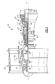
- a fan blade 60 of the fan blade assembly 42 may include a root 62 supporting a platform 64.
- An airfoil 66 may extend from the platform 64 to a tip 68.
- the airfoil 66 includes spaced apart leading and trailing edges 70, 72. Pressure and suction sides 74, 76 adjoin the leading and trailing edges 70, 72 to provide a fan blade contour 78.
- the fan blade includes a leading edge sheath 80.
- the sheath 80 is secured to the fan blade 60 over the edge 82.
- the sheath 80 is constructed from titanium.
- the sheath 80 is made from titanium alloy. It should be understood that other metals or materials may be used for sheath 80.
- the fan blade 60 may include a core 84 of a first material surrounded by a shell 86 of a second material.
- the core 84 may extend from the about the tip 68 to about the root 62.
- the core 84 may extend from about the leading edge 70 to about the trailing edge 72.
- the fan blade may include a second core (not shown) being made of the first material surrounded by the shell 86.
- a second material has less plasticity than the first material.
- the first material may be aramid fiber and the second material may be carbon-fiber.
- a first material may be selected from the group consisting of metallic foam, ceramic foam, polyurethane foam, polystyrene, blown polystyrene, nylon fiber, glass fiber, silicone, polypropylene, polypropylene fibers, polyethylene, polyethylene fibers, hydrogel, aerogel, xerogel, and organogel. Even more, a first material need not be made only of from one of these afore mentioned materials. As such, a first material may be made from the combination of any of the foregoing.
- metallic foam may be selected from the group comprising aluminum foam, aluminum alloy foam, nickel foam, nickel alloy foam, titanium foam and titanium alloy foam.
- a first material may be made from one or more of the above mentioned metallic foams.
- an aramid fiber may selected from the group consisting of para-aramid fiber (Kevlar®) and meta-aramid fiber (Nomex®). Furthermore, a first material may be made from a combination of both para-aramid fiber and meta-aramid fiber.
- the silicone of a first material may be selected from the group consisting of silicone fluid, silicone elastomer, silicone gel and silicone resin.
- a first material may also be made of a combination of any two or more of afore mentioned silicones too.
- the choice of a first material described above, and any combinations thereof, may be chosen by a skilled artisan to provide sufficient strength and structural integrity to the fan blade.
- a first material is not limited to aramid fiber
- a second material is not meant to be limited to only carbon-fiber.
- the second material has less plasticity than the first material.
- a second material may be selected from the group comprising steel, titanium, titanium alloy, nickel, nickel alloy, ceramic, poly(p-phenylene-2,6-benzobisoxazole) fiber, mullite fiber, alumina fiber, silicon nitride fiber, silicon carbide fiber, boron fiber, boron nitride fiber, boron carbide fiber, glass fiber, titanium diboride fibers, yttria stabilized zirconium fiber, or any combination thereof.
- a second material may be made from the combination of two or more of any of the foregoing.
- a carbon-fiber may be selected from the group comprising woven carbon-fiber, unidirectional carbon-fiber or any combination thereof.
- the second material may be made from combinations of any two or more of the foregoing. The choice of a second material described above, and any combinations thereof, may be chosen to provide sufficient strength and structural integrity to the fan blade in combination with a first material.
- the thickness of core 84 may vary based on its position between the tip 68 and the platform 64 and the leading edge 70 and trailing edge 72.
- the core may be between about 0.001 inches thick and 3 inches thick.
- the core may be between about 0.01 inches thick and about 2 inches thick.
- the core may be between about 0.1 inches thick and about 2 inches thick.
- the thickness of the core may positionally vary to provide appropriate absorptive capability to the blade upon exposure to foreign objects, while still providing appropriate strength to carry the operational load of the blade.
- the appropriate thickness of the core may be determined using computer software modeling and then confirmed with a test complying with Federal Aviation Regulations (FARs), 14 C.F.R., Subpart E and/or its European Aviation Safety Agency (EASA) equivalents.
- FARs Federal Aviation Regulations
- EASA European Aviation Safety Agency
- the thickness of the shell 86 may also vary based on its position between the tip 68 and the platform 64 and the leading edge 70 and trailing edge 72. Thus, in one example the shell is between about 0.001 inches thick and 3 inches thick. In a further example, the shell is between about 0.01 inches thick and about 2 inches thick. In a still further example, the shell is between about 0.1 inches thick and about 2 inches thick. The thickness of the shell may positionally vary to provide appropriate slicing capability to the blade upon exposure to foreign objects, while still providing the appropriate strength to carry the operational load of the blade.
- the appropriate thickness of the shell may be modeled with computer software and subsequently confirmed with a test complying with FARs, 14 C.F.R., Subpart E and/or its EASA equivalents.
- a completed blade 27 having a core and a shell with varying thickness may be modeled with computer software and subsequently confirmed with a test complying with FARs, 14 C.F.R., Subpart E and/or its EASA equivalents.
- the present disclosure also recites a method for making a composite fan blade for a gas turbine engine.
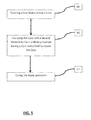
- An exemplary embodiment of the method is depicted in the flowchart of FIG. 5 .
- the method may include a first step 88 of forming a first material into a core.
- the core may be enclosed with a second material to form a blade precursor.
- the blade-precursor may have a core and a shell surrounding the core.
- the blade-precursor may be cured.
- the core may be shaped into an airfoil shape.
- the core may not have any airfoil shape, and instead the shell may have an airfoil shape.
- the core or shell has an airfoil shape may be dependent on many variables such as, but not limited to, the thickness of the blade, the first material used, and the second material used. Thus, if the blade is towards its lower thickness limit, then the core may not be in an airfoil shape, and instead the shell may be relied upon to provide an airfoil shape.
- whether the core is an airfoil shape may be dependent on the results of the computer modeling discussed above for a particular combination of first material and second material.
- the core of a fan blade having a para-aramid core may be in the shape of an airfoil to provide the necessary absorptive capability while still providing appropriate strength to carry the operational load of the blade when utilized in combination with a carbon-fiber shell.
- the first material may include a first matrix
- the second material may include a second matrix.
- the matrices may be utilized to act as a binder for the first material and second material.
- the first and second matrices that may be used include, but are not limited to, epoxy resin, phenolic resin, polyimide resin, polyamide resin, polypropylene resin and polyether ether ketone (PEEK) resin.
- PEEK polyether ether ketone
- the process in the curing step 92 may be selected from the group consisting of air-curing, heat-curing, catalytic curing, UV curing (if an appropriate UV curable material is used) and electron beam curing.
- the process depicted in the FIG. 5 may include an additional curing step between core forming step 88 and the enclosing step 90. In this instance, the curing processes may be the same or they may be different.
- the blades of the present disclosure can find operation in many industrial settings, including but not limited to, gas turbine engines for use in aircraft. More specifically, various composite fan blades are disclosed.
- the fan blades disclosed herein have a core of a first material that is surrounded by a shell of a second material, with the second material having a lower plasticity than the first material.
- the lower plasticity shell can cut through foreign objects that impinge its surface helping to expel such objects from the engine, while the higher plasticity core material absorbs the energy of an impinging foreign object thereby reducing the likelihood of fracture of the blade and its liberation from engine during foreign object exposure.
Landscapes
- Engineering & Computer Science (AREA)
- Mechanical Engineering (AREA)
- General Engineering & Computer Science (AREA)
- Chemical & Material Sciences (AREA)
- Materials Engineering (AREA)
- Architecture (AREA)
- Combustion & Propulsion (AREA)
- Composite Materials (AREA)
- Structures Of Non-Positive Displacement Pumps (AREA)
Applications Claiming Priority (1)
| Application Number | Priority Date | Filing Date | Title |
|---|---|---|---|
| US201462032922P | 2014-08-04 | 2014-08-04 |
Publications (2)
| Publication Number | Publication Date |
|---|---|
| EP2987992A2 true EP2987992A2 (fr) | 2016-02-24 |
| EP2987992A3 EP2987992A3 (fr) | 2016-04-20 |
Family
ID=53836402
Family Applications (1)
| Application Number | Title | Priority Date | Filing Date |
|---|---|---|---|
| EP15178917.9A Withdrawn EP2987992A3 (fr) | 2014-08-04 | 2015-07-29 | Soufflante de ventilateur composite |
Country Status (2)
| Country | Link |
|---|---|
| US (1) | US20160032729A1 (fr) |
| EP (1) | EP2987992A3 (fr) |
Families Citing this family (16)
| Publication number | Priority date | Publication date | Assignee | Title |
|---|---|---|---|---|
| US20160177732A1 (en) * | 2014-07-22 | 2016-06-23 | United Technologies Corporation | Hollow fan blade for a gas turbine engine |
| USD760978S1 (en) * | 2015-05-13 | 2016-07-05 | Zodiac Pool Systems, Inc. | Blade for pool cleaner |
| US9920546B2 (en) | 2015-05-13 | 2018-03-20 | Zodiac Pool Systems Llc | Components of automatic pool cleaners |
| USD760977S1 (en) | 2015-05-13 | 2016-07-05 | Zodiac Pool Systems, Inc. | Brush for pool cleaner |
| USD796758S1 (en) | 2016-01-08 | 2017-09-05 | Zodiac Pool Systems, Inc. | Brush for pool cleaner |
| KR102212663B1 (ko) * | 2018-05-22 | 2021-02-05 | 주식회사 석영시스템즈 | 목표 온도를 기반으로 하는 빌딩의 열·공조 시스템에 대한 공급 전력 제어 방법 및 장치 |
| FR3103215B1 (fr) | 2019-11-20 | 2021-10-15 | Safran Aircraft Engines | Aube de soufflante rotative de turbomachine, soufflante et turbomachine munies de celle-ci |
| US11225874B2 (en) | 2019-12-20 | 2022-01-18 | Raytheon Technologies Corporation | Turbine engine rotor blade with castellated tip surface |
| US11624287B2 (en) * | 2020-02-21 | 2023-04-11 | Raytheon Technologies Corporation | Ceramic matrix composite component having low density core and method of making |
| US20210388739A1 (en) * | 2020-06-16 | 2021-12-16 | General Electric Company | Composite fan containment case |
| US11655828B2 (en) | 2021-10-27 | 2023-05-23 | General Electric Company | Anti-icing systems and airfoils for a fan section of a turbine engine |
| US11988103B2 (en) | 2021-10-27 | 2024-05-21 | General Electric Company | Airfoils for a fan section of a turbine engine |
| US12228037B1 (en) * | 2023-12-04 | 2025-02-18 | General Electric Company | Guide vane assembly with fixed and variable pitch inlet guide vanes |
| US12473832B2 (en) | 2024-03-13 | 2025-11-18 | General Electric Company | Gas turbine engine having composite fan blades |
| US12473863B2 (en) | 2024-03-13 | 2025-11-18 | General Electric Company | Gas turbine engine having composite fan blades |
| US12577879B1 (en) * | 2025-07-01 | 2026-03-17 | Rtx Corporation | Composite tip and trailing edge reinforcement for composite fan blade |
Family Cites Families (16)
| Publication number | Priority date | Publication date | Assignee | Title |
|---|---|---|---|---|
| US4234092A (en) * | 1978-04-17 | 1980-11-18 | Edwin Axel | Container |
| US20010005946A1 (en) * | 1991-05-07 | 2001-07-05 | Brown Jeffrey W. | Shock reducing footwear and method of manufacture |
| US6755619B1 (en) * | 2000-11-08 | 2004-06-29 | General Electric Company | Turbine blade with ceramic foam blade tip seal, and its preparation |
| ES2361676T3 (es) * | 2001-07-25 | 2011-06-21 | Aceram Materials And Technologies Inc. | Placa de blindaje con capas de desconchadura. |
| WO2004105655A1 (fr) * | 2003-06-02 | 2004-12-09 | Impliant Ltd. | Prothese de disque vertebral |
| GB0516036D0 (en) * | 2005-08-04 | 2005-09-14 | Rolls Royce Plc | Aerofoil |
| GB0601220D0 (en) * | 2006-01-21 | 2006-03-01 | Rolls Royce Plc | Aerofoils for gas turbine engines |
| DE102008058786A1 (de) * | 2008-11-24 | 2010-05-27 | Rolls-Royce Deutschland Ltd & Co Kg | Hybrides Bauteil für ein Gasturbinentriebwerk |
| FR2942278B1 (fr) * | 2009-02-17 | 2015-06-19 | Airbus France | Aube pour recepteur de turbomachine d'aeronef, pourvue de deux ames creuses logees l'une dans l'autre |
| US8075274B2 (en) * | 2009-05-13 | 2011-12-13 | Hamilton Sundstrand Corporation | Reinforced composite fan blade |
| US9004873B2 (en) * | 2010-12-27 | 2015-04-14 | Rolls-Royce Corporation | Airfoil, turbomachine and gas turbine engine |
| US9221120B2 (en) * | 2012-01-04 | 2015-12-29 | United Technologies Corporation | Aluminum fan blade construction with welded cover |
| JP5982837B2 (ja) * | 2012-01-30 | 2016-08-31 | 株式会社Ihi | 航空機用ジェットエンジンのファン動翼 |
| US20130199934A1 (en) * | 2012-02-06 | 2013-08-08 | United Technologies Corporation | Electroformed sheath |
| US9416668B2 (en) * | 2012-04-30 | 2016-08-16 | United Technologies Corporation | Hollow fan bladed with braided fabric tubes |
| US9169731B2 (en) * | 2012-06-05 | 2015-10-27 | United Technologies Corporation | Airfoil cover system |
-
2015
- 2015-05-13 US US14/711,192 patent/US20160032729A1/en not_active Abandoned
- 2015-07-29 EP EP15178917.9A patent/EP2987992A3/fr not_active Withdrawn
Non-Patent Citations (1)
| Title |
|---|
| None |
Also Published As
| Publication number | Publication date |
|---|---|
| US20160032729A1 (en) | 2016-02-04 |
| EP2987992A3 (fr) | 2016-04-20 |
Similar Documents
| Publication | Publication Date | Title |
|---|---|---|
| US20160032729A1 (en) | Composite Fan Blade | |
| US11168568B2 (en) | Composite gas turbine engine component with lattice | |
| CN109415940B (zh) | 用于复合风扇叶片的金属前缘 | |
| EP2469028B1 (fr) | Aube de turbomachine avec une âme en mousse de métal | |
| EP2855849B1 (fr) | Système de cache d'aile portante | |
| EP2961938B1 (fr) | Aube composite d'une moteur de turbine à gaz et procédé | |
| EP3077625B1 (fr) | Aube creuse avec amortisseur interne | |
| US11092021B2 (en) | Fan platform with core and skin | |
| US10669936B2 (en) | Thermally conforming acoustic liner cartridge for a gas turbine engine | |
| EP2952683B1 (fr) | Profil aérodynamique de turbine à gaz avec des propriétés de grande épaisseur | |
| EP3126638B1 (fr) | Surface portante de moteur à turbine à gaz | |
| US20160341071A1 (en) | Compressed chopped fiber composite fan blade platform | |
| CA2953615A1 (fr) | Methode et systeme destines a des panneaux en composite renforces de fibres | |
| EP2915742B2 (fr) | Moteur à turbine à gaz avec cône renforcé | |
| JP4820373B2 (ja) | スタティックガスタービン部分品及びそうした部分品の補修法 | |
| US10273816B2 (en) | Wear pad to prevent cracking of fan blade | |
| US10822970B2 (en) | Gas turbine engine structural guide vanes | |
| EP3090127B1 (fr) | Pale de ventilateur avec empilage de tissu adhésif | |
| US20190338643A1 (en) | Method for manufacturing a component | |
| EP2993300B1 (fr) | Structure de surface portante pour turbine à gaz | |
| EP3667016B1 (fr) | Aube de soufflante comportant un dispositif de mesure intégré pour régler la pression du gaz à l'intérieur de l'aube de soufflante et procedé associé de fabrication d'une aube de soufflante |
Legal Events
| Date | Code | Title | Description |
|---|---|---|---|
| PUAI | Public reference made under article 153(3) epc to a published international application that has entered the european phase |
Free format text: ORIGINAL CODE: 0009012 |
|
| AK | Designated contracting states |
Kind code of ref document: A2 Designated state(s): AL AT BE BG CH CY CZ DE DK EE ES FI FR GB GR HR HU IE IS IT LI LT LU LV MC MK MT NL NO PL PT RO RS SE SI SK SM TR |
|
| AX | Request for extension of the european patent |
Extension state: BA ME |
|
| PUAL | Search report despatched |
Free format text: ORIGINAL CODE: 0009013 |
|
| AK | Designated contracting states |
Kind code of ref document: A3 Designated state(s): AL AT BE BG CH CY CZ DE DK EE ES FI FR GB GR HR HU IE IS IT LI LT LU LV MC MK MT NL NO PL PT RO RS SE SI SK SM TR |
|
| AX | Request for extension of the european patent |
Extension state: BA ME |
|
| RIC1 | Information provided on ipc code assigned before grant |
Ipc: F02K 3/06 20060101AFI20160314BHEP Ipc: F01D 5/14 20060101ALI20160314BHEP Ipc: F01D 5/28 20060101ALI20160314BHEP |
|
| RAP1 | Party data changed (applicant data changed or rights of an application transferred) |
Owner name: UNITED TECHNOLOGIES CORPORATION |
|
| STAA | Information on the status of an ep patent application or granted ep patent |
Free format text: STATUS: REQUEST FOR EXAMINATION WAS MADE |
|
| 17P | Request for examination filed |
Effective date: 20161020 |
|
| RBV | Designated contracting states (corrected) |
Designated state(s): AL AT BE BG CH CY CZ DE DK EE ES FI FR GB GR HR HU IE IS IT LI LT LU LV MC MK MT NL NO PL PT RO RS SE SI SK SM TR |
|
| STAA | Information on the status of an ep patent application or granted ep patent |
Free format text: STATUS: EXAMINATION IS IN PROGRESS |
|
| 17Q | First examination report despatched |
Effective date: 20170324 |
|
| STAA | Information on the status of an ep patent application or granted ep patent |
Free format text: STATUS: THE APPLICATION IS DEEMED TO BE WITHDRAWN |
|
| 18D | Application deemed to be withdrawn |
Effective date: 20200215 |