EP2988175A1 - Bilderzeugungsvorrichtung zur reduzierung der entwicklungslückenvariation an beiden endabschnitten einer entwicklungsrolle - Google Patents
Bilderzeugungsvorrichtung zur reduzierung der entwicklungslückenvariation an beiden endabschnitten einer entwicklungsrolle Download PDFInfo
- Publication number
- EP2988175A1 EP2988175A1 EP15177185.4A EP15177185A EP2988175A1 EP 2988175 A1 EP2988175 A1 EP 2988175A1 EP 15177185 A EP15177185 A EP 15177185A EP 2988175 A1 EP2988175 A1 EP 2988175A1
- Authority
- EP
- European Patent Office
- Prior art keywords
- developing
- drive unit
- forming apparatus
- image forming
- unit
- Prior art date
- Legal status (The legal status is an assumption and is not a legal conclusion. Google has not performed a legal analysis and makes no representation as to the accuracy of the status listed.)
- Granted
Links
Images




Classifications
-
- G—PHYSICS
- G03—PHOTOGRAPHY; CINEMATOGRAPHY; ANALOGOUS TECHNIQUES USING WAVES OTHER THAN OPTICAL WAVES; ELECTROGRAPHY; HOLOGRAPHY
- G03G—ELECTROGRAPHY; ELECTROPHOTOGRAPHY; MAGNETOGRAPHY
- G03G15/00—Apparatus for electrographic processes using a charge pattern
- G03G15/06—Apparatus for electrographic processes using a charge pattern for developing
- G03G15/065—Arrangements for controlling the potential of the developing electrode
-
- G—PHYSICS
- G03—PHOTOGRAPHY; CINEMATOGRAPHY; ANALOGOUS TECHNIQUES USING WAVES OTHER THAN OPTICAL WAVES; ELECTROGRAPHY; HOLOGRAPHY
- G03G—ELECTROGRAPHY; ELECTROPHOTOGRAPHY; MAGNETOGRAPHY
- G03G15/00—Apparatus for electrographic processes using a charge pattern
- G03G15/06—Apparatus for electrographic processes using a charge pattern for developing
- G03G15/08—Apparatus for electrographic processes using a charge pattern for developing using a solid developer, e.g. powder developer
- G03G15/0806—Apparatus for electrographic processes using a charge pattern for developing using a solid developer, e.g. powder developer on a donor element, e.g. belt, roller
-
- G—PHYSICS
- G03—PHOTOGRAPHY; CINEMATOGRAPHY; ANALOGOUS TECHNIQUES USING WAVES OTHER THAN OPTICAL WAVES; ELECTROGRAPHY; HOLOGRAPHY
- G03G—ELECTROGRAPHY; ELECTROPHOTOGRAPHY; MAGNETOGRAPHY
- G03G15/00—Apparatus for electrographic processes using a charge pattern
- G03G15/06—Apparatus for electrographic processes using a charge pattern for developing
- G03G15/08—Apparatus for electrographic processes using a charge pattern for developing using a solid developer, e.g. powder developer
- G03G15/0822—Arrangements for preparing, mixing, supplying or dispensing developer
- G03G15/0865—Arrangements for supplying new developer
-
- G—PHYSICS
- G03—PHOTOGRAPHY; CINEMATOGRAPHY; ANALOGOUS TECHNIQUES USING WAVES OTHER THAN OPTICAL WAVES; ELECTROGRAPHY; HOLOGRAPHY
- G03G—ELECTROGRAPHY; ELECTROPHOTOGRAPHY; MAGNETOGRAPHY
- G03G21/00—Arrangements not provided for by groups G03G13/00 - G03G19/00, e.g. cleaning, elimination of residual charge
- G03G21/16—Mechanical means for facilitating the maintenance of the apparatus, e.g. modular arrangements
- G03G21/1642—Mechanical means for facilitating the maintenance of the apparatus, e.g. modular arrangements for connecting the different parts of the apparatus
- G03G21/1647—Mechanical connection means
-
- G—PHYSICS
- G03—PHOTOGRAPHY; CINEMATOGRAPHY; ANALOGOUS TECHNIQUES USING WAVES OTHER THAN OPTICAL WAVES; ELECTROGRAPHY; HOLOGRAPHY
- G03G—ELECTROGRAPHY; ELECTROPHOTOGRAPHY; MAGNETOGRAPHY
- G03G2221/00—Processes not provided for by group G03G2215/00, e.g. cleaning or residual charge elimination
- G03G2221/16—Mechanical means for facilitating the maintenance of the apparatus, e.g. modular arrangements and complete machine concepts
- G03G2221/1651—Mechanical means for facilitating the maintenance of the apparatus, e.g. modular arrangements and complete machine concepts for connecting the different parts
- G03G2221/1657—Mechanical means for facilitating the maintenance of the apparatus, e.g. modular arrangements and complete machine concepts for connecting the different parts transmitting mechanical drive power
Definitions
- An image forming apparatus performs to develop a latent image formed on an image carrier, which is constituted of such as a photoreceptor, with a developing device to visualize the latent image as a toner image.
- the developing device houses a developer including toner in a developing container, includes a developing roller supplying the image carrier with developer, and includes a stir conveying member supplying the developing roller with the developer housed in the developing container with stirring and conveying the developer.
- an image forming apparatus including a developing pulley located at both ends of a rotation shaft of the developing roller and a pressing member located to press the developing roller to the photoreceptor drum is widely employed.
- the developing pulley is in contact with the outer peripheral surface of the photoreceptor drum and is rotationally driven with respect to the photoreceptor drum. This ensures the developing roller to rotate with respect to the photoreceptor drum in a state keeping a predetermined development gap.
- a typical developing device employs a configuration including a development drive unit to rotatably drive the developing roller in the developing device and transmitting a rotary drive power from the developing device main body side to the development drive unit via a gear.
- a configuration including a replenishment drive unit to rotatably drive a toner replenishment screw of a toner replenishment container in the developing device and transmitting a rotary drive power from the developing device main body side to the replenishment drive unit via a gear is also employed.
- An image forming apparatus transmitting a rotary drive power to a developing roller via a gear has been proposed.
- An image forming apparatus includes an image forming apparatus body, a first driving mechanism, a first drive unit, an image carrier, a developing device, and a biasing member.
- the first driving mechanism is located in the image forming apparatus body.
- the first drive unit includes an input unit to which a rotary drive power is transmitted from the first driving mechanism.
- the image carrier carries an electrostatic latent image.
- the developing device is removably attachable to the image forming apparatus body.
- the developing device forms a toner image on the surface of the image carrier.
- the toner image corresponds to the electrostatic latent image.
- the biasing member biases the developing device toward the image carrier side.
- the developing device includes a developing roller supplying toner onto the image carrier, and a developing unit housing and supporting the developing roller.
- the first drive unit is located at one end portion in an axial direction of the developing roller.
- the developing unit swings to come close to the image carrier by the biasing member biasing the developing unit.
- the developing unit is
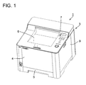
- the image forming apparatus 1 includes an apparatus main body (image forming apparatus body) 3 with an approximately hexahedron structure.
- a front side portion of the apparatus main body 3 facing to a user includes a front cover 4 and a paper sheet cassette 5.
- the front cover 4 is mounted so as to be freely open and close facing to the apparatus main body 3. When opened, the front cover 4 functions as a manual paper feed tray.
- the paper sheet cassette 5 is removably mounted on the apparatus main body 3.
- a discharge tray 6 for paper sheets discharged and an operation unit 7 including such as a plurality of buttons are located on the top of the apparatus main body 3.
- the apparatus main body 3 internally includes an image forming unit, a fixing unit, a paper sheet conveyance passage, and similar unit (not shown).
- the image forming unit transfers a toner image to a supplied paper sheet based on image data retrieved from a host device such as a PC to form an image.
- the image forming unit includes a photoreceptor drum 8, a charging unit, an exposure unit, a developing device 2, a transfer roller, a cleaning blade, and similar unit.
- the photoreceptor drum 8 carries an electrostatic latent image (described below).
- the charging unit charges the surface of the photoreceptor drum 8.
- the exposure unit forms the electrostatic latent image corresponding to a document image on the surface of the photoreceptor drum 8 with such as a laser beam.
- the developing device 2 attaches developer to the formed electrostatic latent image to form a toner image (described below).
- the transfer roller transfers the toner image to a paper sheet.
- the cleaning blade removes a toner remaining on the surface of the photoreceptor drum.
- the fixing unit heats and applies pressure to the paper sheet, on which the toner image is transferred, to fix the toner image on the paper sheet.
- a cover member 9 is mounted so as to be freely open and close facing to the apparatus main body 3.
- the developing device 2 described below is replaceable from the right-side surface of the apparatus main body 3 by opening the cover member 9.
- the image forming apparatus 1 is a tandem type color printer, and includes the developing devices 2 and the photoreceptor drums (image carriers) 8 corresponding to respective colors of magenta, cyan, yellow, and black.
- the developing devices 2 each have a similar configuration and perform similarly.
- the photoreceptor drums 8 each have a similar configuration and perform similarly.
- the developing device 2 is constituted of a developing roller (developer carrier) 20, a regulating blade 21, a stir conveying member 23, a developing container (developing unit) 22, and similar unit.
- the developing container 22 constitutes the outside of the developing device 2. At the lower portion of the developing container 22, the developing container 22 is divided into a first conveying chamber 22c and a second conveying chamber 22d by a partition portion 22b.
- the first conveying chamber 22c and the second conveying chamber 22d house a developer containing a magnetic carrier and a toner.
- the developing container 22 rotatably holds the stir conveying member 23 and the developing roller 20. Further, the developing container 22 includes an opening 22a that exposes the developing roller 20 toward the photoreceptor drum 8.
- the developing roller 20 faces to the photoreceptor drum 8.
- the developing roller 20 is located adjacent to the photoreceptor drum 8 with a predetermined space.
- the developing roller 20 supplies the photoreceptor drum 8 with toner.
- the stir conveying member 23 is located approximately downward of the developing roller 20.
- the regulating blade 21 is fixed and held onto the developing container 22 at the right obliquely downward of the developing roller 20.
- the developing roller 20 includes a rotation shaft 20a, a magnetic pole member 20b, a development sleeve 20c, which is formed of a non-magnetic metallic material in a cylindrical shape, and similar component.
- the rotation shaft 20a is rotatably supported to the developing container 22.
- This rotation shaft 20a holds the development sleeve 20c so as to rotate integrally with the rotation shaft 20a. Further, the rotation shaft 20a holds the magnetic pole member 20b made of a magnet at a position facing to a second spiral 23b with a predetermined distance from the development sleeve 20c.
- the stir conveying member 23 includes two spirals of a first spiral 23a and the second spiral 23b.
- the second spiral 23b is located in the second conveying chamber 22d below the developing roller 20, while the first spiral 23a is located in the first conveying chamber 22c adjacently to the left side of the second spiral 23b.
- the first spiral 23a and the second spiral 23b stir the developer to charge the toner included in the developer to a predetermined level. This ensures the toner to be held onto carrier.
- the partition portion 22b which divides the first conveying chamber 22c and the second conveying chamber 22d, in the long side direction (front and back direction of the paper sheet surface in FIG. 2 ), communication units are located.
- the first spiral 23a rotates, the charged developer is conveyed from the one communication unit located on the partition portion 22b to the second spiral 23b, and the developer circulates in the first conveying chamber 22c and the second conveying chamber 22d.
- the second spiral 23b supplies the developing roller 20 with the developer.
- the developing container 22 includes bearing portions 22e and 22f that support a swinging shaft 10 secured to the apparatus main body 3 (see FIG. 3 and FIG. 4 ).
- the developing container 22 is configured swingably centering the swinging shaft 10.
- the developing container 22 includes a pressing surface 22g (see FIG. 2 and FIG. 5 ). When the pressing surface 22g is pressed by a biasing member 11 (see FIG. 2 ), which is constituted of such as a compression coil spring, the developing container 22 swings such that the developing roller 20 comes close to the photoreceptor drum 8.
- developing pulleys 20d are located at both ends of the rotation shaft 20a of the developing roller 20, developing pulleys 20d are located.
- the developing pulley 20d has a radius formed in a size where a size of the development gap is added to the radius of the development sleeve 20c.
- the developing roller 20 rotates with respect to the photoreceptor drum 8 in a state keeping a predetermined development gap.
- a replenishment drive unit (first drive unit) 30 and a development drive unit (second drive unit) 40 are respectively located.
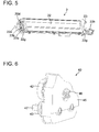
- the development drive unit 40 transmits rotary drive power to the developing roller 20 and the stir conveying member 23. As illustrated in FIG. 6 and FIG. 7 , the development drive unit 40 includes an input gear 41, a developing roller gear 42, transmission gears 43 and 44, and a cover member 45, which covers the side portion of these gears.
- the input gear 41 is configured to receive the rotary drive power from a development driving mechanism (second driving mechanism) via a coupling joint 46.
- the development driving mechanism includes a motor, a gear train, and similar component, which are located in the apparatus main body 3 (not shown).
- the input gear 41 is configured to transmit the rotary drive power to the developing roller gear 42 and the transmission gears 43 and 44.
- the developing roller gear 42 is secured to an end portion of the rotation shaft 20a of the developing roller 20.
- the developing roller gear 42 is configured to transmit the rotary drive power to the development sleeve 20c of the developing roller 20 to rotate the development sleeve 20c.
- the transmission gear 43 is secured to a transmission shaft 47 engaging with the second spiral 23b, while the transmission gear 44 is secured to a transmission shaft 48 engaging with the first spiral 23a. This ensures the development sleeve 20c, the first spiral 23a, and the second spiral 23b to rotate when the input gear 41 rotates.
- the development drive unit 40 is secured to the developing container 22. This ensures the development drive unit 40 to swing centering the swinging shaft 10 when the developing container 22 swings centering the swinging shaft 10.
- the replenishment drive unit 30 transmits the rotary drive power to a toner replenishment screw 12a of a toner replenishment container 12, which houses a toner to replenish to the developing device 2.
- the replenishment drive unit 30 includes an input gear (input unit) 31, a transmission member 32, and a cover member 33, which rotatably supports the input gear 31 and the transmission member 32.
- the input gear 31 is configured to receive the rotary drive power from a replenishment driving mechanism (first driving mechanism) 51 via a gear 51 a (see FIG. 10 ).
- the replenishment driving mechanism (first driving mechanism) 51 includes a motor (not shown), a gear train, and similar component, which are located in the apparatus main body 3.
- the input gear 31 is configured to transmit the rotary drive power to a gear portion 32a of the transmission member 32.
- the transmission member 32 includes the gear portion 32a and an engaging portion 32b.
- the gear portion 32a meshes with the input gear 31.
- the engaging portion 32b engages with the toner replenishment screw 12a (see FIG. 3 ) located in the toner replenishment container 12.
- the transmission member 32 transmits the rotary drive power from the input gear 31 to the toner replenishment screw 12a to rotate the toner replenishment screw 12a.
- the rotation of the toner replenishment screw 12a causes the toner in the toner replenishment container 12 to be replenished by a predetermined amount from an opening 22h (see FIG. 4 ) located upstream side of the first conveying chamber 22c in the developing container 22.
- the replenishment drive unit 30 is configured swingably with respect to the developing container 22.
- the replenishment drive unit 30 is secured to the apparatus main body 3 by positioning of the insertion hole 33a and the rotation shaft of the input gear 31. This ensures the developing container 22 to swing with respect to the replenishment drive unit 30 centering the swinging shaft 10.
- a center shaft for swinging (swinging shaft 10) of the developing container 22 with respect to the replenishment drive unit 30 is located coaxially with a center shaft for swinging (swinging shaft 10) of the developing container 22 with respect to the apparatus main body 3.
- a swing angle (swing range) of the developing container 22 with respect to the replenishment drive unit 30 is regulated.
- the developing container 22 includes a regulating piece 22i, while the cover member 33 has a regulating hole (regulating portion) 33b to which the regulating piece 22i is inserted.
- the developing container 22 can swing within a movable range of the regulating piece 22i with respect to the regulating hole 33b.
- the developing container 22 at one end portion and the other end portion of which the replenishment drive unit 30 and the development drive unit 40 are respectively mounted, is mounted to the apparatus main body 3 in a state where the photoreceptor drum 8 is removed.
- pressing the pressing surface 22g of the developing container 22 by the biasing member 11 causes the developing container 22 and the development drive unit 40 to swing in the right rotation direction so as to come close to the photoreceptor drum 8.
- the swing angles of the developing container 22 and the development drive unit 40 are regulated by the regulating piece 22i of the developing container 22 and the regulating hole 33b of the cover member 33.
- the developing container 22 is swingable with respect to the replenishment drive unit 30.
- the power causes the replenishment drive unit 30 to swing with respect to the developing container 22 with engaging of the gear 51a and the input gear 31.
- securing the replenishment drive unit 30 to the apparatus main body 3 can cause the apparatus main body 3 to absorb the power acting on the replenishment drive unit 30 to swing.
- the development drive unit 40 may be secured to the developing container 22 because the transmitted rotary drive power is less likely to act on the developing container 22 to swing.
- the center shaft for swinging (swinging shaft 10) of the developing container 22 with respect to the replenishment drive unit 30 is coaxial with the center shaft for swinging (swinging shaft 10) of the developing container 22 with respect to the apparatus main body 3. This achieves space saving compared with the case where the center shaft for swinging of the developing container 22 with respect to the replenishment drive unit 30 is not coaxial with the center shaft for swinging of the developing container 22 with respect to the apparatus main body 3.
- the developing container 22 includes the regulating piece 22i, while the replenishment drive unit 30 includes the regulating hole 33b.
- the regulating hole 33b regulates the swing range of the developing container 22 with respect to the replenishment drive unit 30 by the regulating piece 22i in contact with the regulating hole 33b. This ensures regulating the swing range of the developing container 22 with respect to the replenishment drive unit 30 easily.
- the above-described embodiment shows an exemplary case where the center shaft for swinging of the developing container 22 with respect to the replenishment drive unit 30 is located coaxially with the center shaft for swinging of the developing container 22 with respect to the apparatus main body 3.
- the disclosure should not be construed in a limiting sense.
- the center shaft for swinging of the developing container 22 with respect to the replenishment drive unit 30 may be located not coaxially with the center shaft for swinging of the developing container 22 with respect to the apparatus main body 3.
- the developing container 22 is configured swingably with respect to the replenishment drive unit 30 and the development drive unit 40 is secured to the developing container 22, the disclosure should not be construed in a limiting sense.
- the developing container 22 may be configured swingably with respect to the development drive unit 40. In this case, using such as a flexible joint ensures transmitting the rotary drive power from the development drive unit 40 to the developing container 22 easily.
- a drive unit other than the replenishment drive unit 30 may be located such that the developing container 22 is configured to be swingable with respect to the drive unit.
Landscapes
- Physics & Mathematics (AREA)
- General Physics & Mathematics (AREA)
- Dry Development In Electrophotography (AREA)
- Electrophotography Configuration And Component (AREA)
Applications Claiming Priority (1)
| Application Number | Priority Date | Filing Date | Title |
|---|---|---|---|
| JP2014169787A JP6237534B2 (ja) | 2014-08-22 | 2014-08-22 | 画像形成装置 |
Publications (2)
| Publication Number | Publication Date |
|---|---|
| EP2988175A1 true EP2988175A1 (de) | 2016-02-24 |
| EP2988175B1 EP2988175B1 (de) | 2020-02-12 |
Family
ID=53673811
Family Applications (1)
| Application Number | Title | Priority Date | Filing Date |
|---|---|---|---|
| EP15177185.4A Active EP2988175B1 (de) | 2014-08-22 | 2015-07-17 | Bilderzeugungsvorrichtung zur reduzierung der entwicklungslückenvariation an beiden endabschnitten einer entwicklungsrolle |
Country Status (4)
| Country | Link |
|---|---|
| US (1) | US9442414B2 (de) |
| EP (1) | EP2988175B1 (de) |
| JP (1) | JP6237534B2 (de) |
| CN (1) | CN106200307B (de) |
Citations (4)
| Publication number | Priority date | Publication date | Assignee | Title |
|---|---|---|---|---|
| EP0833228A1 (de) * | 1996-09-26 | 1998-04-01 | Canon Kabushiki Kaisha | Kupplungsteil, photoempfindliche Trommel, Arbeitseinheit und elektrophotographisches Bilderzeugungsgerät |
| US20020181974A1 (en) * | 2001-05-30 | 2002-12-05 | Canon Kabushiki Kaisha | Developing device |
| US20090123194A1 (en) * | 2007-11-09 | 2009-05-14 | Canon Kabushiki Kaisha | Image forming apparatus |
| US20120099905A1 (en) * | 2010-10-25 | 2012-04-26 | Canon Kabushiki Kaisha | Developing apparatus and image forming apparatus |
Family Cites Families (4)
| Publication number | Priority date | Publication date | Assignee | Title |
|---|---|---|---|---|
| JPH0535076A (ja) | 1991-07-25 | 1993-02-12 | Asahi Optical Co Ltd | 現像装置の回転力入力ギア配置構造 |
| JP4087915B2 (ja) * | 1996-11-19 | 2008-05-21 | セイコーエプソン株式会社 | 画像形成装置 |
| JP5111238B2 (ja) * | 2008-05-27 | 2013-01-09 | キヤノン株式会社 | プロセスカートリッジ |
| JP6004690B2 (ja) * | 2012-03-21 | 2016-10-12 | キヤノン株式会社 | プロセスカートリッジ及び画像形成装置 |
-
2014
- 2014-08-22 JP JP2014169787A patent/JP6237534B2/ja active Active
-
2015
- 2015-07-15 CN CN201510415752.9A patent/CN106200307B/zh active Active
- 2015-07-17 EP EP15177185.4A patent/EP2988175B1/de active Active
- 2015-08-22 US US14/833,089 patent/US9442414B2/en active Active
Patent Citations (4)
| Publication number | Priority date | Publication date | Assignee | Title |
|---|---|---|---|---|
| EP0833228A1 (de) * | 1996-09-26 | 1998-04-01 | Canon Kabushiki Kaisha | Kupplungsteil, photoempfindliche Trommel, Arbeitseinheit und elektrophotographisches Bilderzeugungsgerät |
| US20020181974A1 (en) * | 2001-05-30 | 2002-12-05 | Canon Kabushiki Kaisha | Developing device |
| US20090123194A1 (en) * | 2007-11-09 | 2009-05-14 | Canon Kabushiki Kaisha | Image forming apparatus |
| US20120099905A1 (en) * | 2010-10-25 | 2012-04-26 | Canon Kabushiki Kaisha | Developing apparatus and image forming apparatus |
Also Published As
| Publication number | Publication date |
|---|---|
| CN106200307A (zh) | 2016-12-07 |
| JP6237534B2 (ja) | 2017-11-29 |
| CN106200307B (zh) | 2019-07-05 |
| US9442414B2 (en) | 2016-09-13 |
| JP2016045373A (ja) | 2016-04-04 |
| EP2988175B1 (de) | 2020-02-12 |
| US20160054677A1 (en) | 2016-02-25 |
Similar Documents
| Publication | Publication Date | Title |
|---|---|---|
| US9910401B2 (en) | Cartridge and member used for cartridge | |
| US9176457B2 (en) | Image forming apparatus and waste toner conveying device incorporated in same | |
| US9274457B2 (en) | Developing cartridge | |
| EP2230569B1 (de) | Bilderzeugungsvorrichtung | |
| JP2015031762A (ja) | 画像形成装置 | |
| JP2013054056A (ja) | カートリッジ | |
| WO2014010120A1 (ja) | カートリッジおよび画像形成装置 | |
| US8995888B2 (en) | Image forming apparatus and development device | |
| JP5017475B1 (ja) | 画像形成装置およびトナーコンテナ | |
| JP2009139490A (ja) | 画像形成装置 | |
| JP5788742B2 (ja) | 現像カートリッジ | |
| EP2988175B1 (de) | Bilderzeugungsvorrichtung zur reduzierung der entwicklungslückenvariation an beiden endabschnitten einer entwicklungsrolle | |
| CN102955400B (zh) | 显影装置和成像设备 | |
| JP2014145794A (ja) | 現像装置 | |
| JP6351455B2 (ja) | 画像形成装置 | |
| JP2014029564A (ja) | カートリッジ | |
| JP5962274B2 (ja) | 現像カートリッジ | |
| JP5211253B2 (ja) | 画像形成装置 | |
| JP3166044U (ja) | 画像形成装置 | |
| JP5936031B2 (ja) | 画像形成装置 | |
| JP2016133712A (ja) | 現像装置およびそれを備えた画像形成装置 | |
| CN115335778A (zh) | 鼓单元和图像形成装置 | |
| JP2007017463A (ja) | 画像形成装置 | |
| JP2012226358A (ja) | 画像形成装置およびトナーコンテナ | |
| JP2012226357A (ja) | 画像形成装置およびトナーコンテナ |
Legal Events
| Date | Code | Title | Description |
|---|---|---|---|
| PUAI | Public reference made under article 153(3) epc to a published international application that has entered the european phase |
Free format text: ORIGINAL CODE: 0009012 |
|
| AK | Designated contracting states |
Kind code of ref document: A1 Designated state(s): AL AT BE BG CH CY CZ DE DK EE ES FI FR GB GR HR HU IE IS IT LI LT LU LV MC MK MT NL NO PL PT RO RS SE SI SK SM TR |
|
| AX | Request for extension of the european patent |
Extension state: BA ME |
|
| 17P | Request for examination filed |
Effective date: 20160615 |
|
| RBV | Designated contracting states (corrected) |
Designated state(s): AL AT BE BG CH CY CZ DE DK EE ES FI FR GB GR HR HU IE IS IT LI LT LU LV MC MK MT NL NO PL PT RO RS SE SI SK SM TR |
|
| GRAP | Despatch of communication of intention to grant a patent |
Free format text: ORIGINAL CODE: EPIDOSNIGR1 |
|
| STAA | Information on the status of an ep patent application or granted ep patent |
Free format text: STATUS: GRANT OF PATENT IS INTENDED |
|
| INTG | Intention to grant announced |
Effective date: 20191113 |
|
| GRAS | Grant fee paid |
Free format text: ORIGINAL CODE: EPIDOSNIGR3 |
|
| GRAA | (expected) grant |
Free format text: ORIGINAL CODE: 0009210 |
|
| STAA | Information on the status of an ep patent application or granted ep patent |
Free format text: STATUS: THE PATENT HAS BEEN GRANTED |
|
| AK | Designated contracting states |
Kind code of ref document: B1 Designated state(s): AL AT BE BG CH CY CZ DE DK EE ES FI FR GB GR HR HU IE IS IT LI LT LU LV MC MK MT NL NO PL PT RO RS SE SI SK SM TR |
|
| REG | Reference to a national code |
Ref country code: GB Ref legal event code: FG4D |
|
| REG | Reference to a national code |
Ref country code: CH Ref legal event code: EP |
|
| REG | Reference to a national code |
Ref country code: AT Ref legal event code: REF Ref document number: 1232933 Country of ref document: AT Kind code of ref document: T Effective date: 20200215 |
|
| REG | Reference to a national code |
Ref country code: IE Ref legal event code: FG4D |
|
| REG | Reference to a national code |
Ref country code: DE Ref legal event code: R096 Ref document number: 602015046668 Country of ref document: DE |
|
| PG25 | Lapsed in a contracting state [announced via postgrant information from national office to epo] |
Ref country code: NO Free format text: LAPSE BECAUSE OF FAILURE TO SUBMIT A TRANSLATION OF THE DESCRIPTION OR TO PAY THE FEE WITHIN THE PRESCRIBED TIME-LIMIT Effective date: 20200512 Ref country code: RS Free format text: LAPSE BECAUSE OF FAILURE TO SUBMIT A TRANSLATION OF THE DESCRIPTION OR TO PAY THE FEE WITHIN THE PRESCRIBED TIME-LIMIT Effective date: 20200212 Ref country code: FI Free format text: LAPSE BECAUSE OF FAILURE TO SUBMIT A TRANSLATION OF THE DESCRIPTION OR TO PAY THE FEE WITHIN THE PRESCRIBED TIME-LIMIT Effective date: 20200212 |
|
| REG | Reference to a national code |
Ref country code: LT Ref legal event code: MG4D |
|
| REG | Reference to a national code |
Ref country code: NL Ref legal event code: MP Effective date: 20200212 |
|
| PG25 | Lapsed in a contracting state [announced via postgrant information from national office to epo] |
Ref country code: IS Free format text: LAPSE BECAUSE OF FAILURE TO SUBMIT A TRANSLATION OF THE DESCRIPTION OR TO PAY THE FEE WITHIN THE PRESCRIBED TIME-LIMIT Effective date: 20200612 Ref country code: SE Free format text: LAPSE BECAUSE OF FAILURE TO SUBMIT A TRANSLATION OF THE DESCRIPTION OR TO PAY THE FEE WITHIN THE PRESCRIBED TIME-LIMIT Effective date: 20200212 Ref country code: LV Free format text: LAPSE BECAUSE OF FAILURE TO SUBMIT A TRANSLATION OF THE DESCRIPTION OR TO PAY THE FEE WITHIN THE PRESCRIBED TIME-LIMIT Effective date: 20200212 Ref country code: HR Free format text: LAPSE BECAUSE OF FAILURE TO SUBMIT A TRANSLATION OF THE DESCRIPTION OR TO PAY THE FEE WITHIN THE PRESCRIBED TIME-LIMIT Effective date: 20200212 Ref country code: BG Free format text: LAPSE BECAUSE OF FAILURE TO SUBMIT A TRANSLATION OF THE DESCRIPTION OR TO PAY THE FEE WITHIN THE PRESCRIBED TIME-LIMIT Effective date: 20200512 Ref country code: GR Free format text: LAPSE BECAUSE OF FAILURE TO SUBMIT A TRANSLATION OF THE DESCRIPTION OR TO PAY THE FEE WITHIN THE PRESCRIBED TIME-LIMIT Effective date: 20200513 |
|
| PG25 | Lapsed in a contracting state [announced via postgrant information from national office to epo] |
Ref country code: NL Free format text: LAPSE BECAUSE OF FAILURE TO SUBMIT A TRANSLATION OF THE DESCRIPTION OR TO PAY THE FEE WITHIN THE PRESCRIBED TIME-LIMIT Effective date: 20200212 |
|
| PG25 | Lapsed in a contracting state [announced via postgrant information from national office to epo] |
Ref country code: ES Free format text: LAPSE BECAUSE OF FAILURE TO SUBMIT A TRANSLATION OF THE DESCRIPTION OR TO PAY THE FEE WITHIN THE PRESCRIBED TIME-LIMIT Effective date: 20200212 Ref country code: RO Free format text: LAPSE BECAUSE OF FAILURE TO SUBMIT A TRANSLATION OF THE DESCRIPTION OR TO PAY THE FEE WITHIN THE PRESCRIBED TIME-LIMIT Effective date: 20200212 Ref country code: PT Free format text: LAPSE BECAUSE OF FAILURE TO SUBMIT A TRANSLATION OF THE DESCRIPTION OR TO PAY THE FEE WITHIN THE PRESCRIBED TIME-LIMIT Effective date: 20200705 Ref country code: SK Free format text: LAPSE BECAUSE OF FAILURE TO SUBMIT A TRANSLATION OF THE DESCRIPTION OR TO PAY THE FEE WITHIN THE PRESCRIBED TIME-LIMIT Effective date: 20200212 Ref country code: LT Free format text: LAPSE BECAUSE OF FAILURE TO SUBMIT A TRANSLATION OF THE DESCRIPTION OR TO PAY THE FEE WITHIN THE PRESCRIBED TIME-LIMIT Effective date: 20200212 Ref country code: EE Free format text: LAPSE BECAUSE OF FAILURE TO SUBMIT A TRANSLATION OF THE DESCRIPTION OR TO PAY THE FEE WITHIN THE PRESCRIBED TIME-LIMIT Effective date: 20200212 Ref country code: SM Free format text: LAPSE BECAUSE OF FAILURE TO SUBMIT A TRANSLATION OF THE DESCRIPTION OR TO PAY THE FEE WITHIN THE PRESCRIBED TIME-LIMIT Effective date: 20200212 Ref country code: DK Free format text: LAPSE BECAUSE OF FAILURE TO SUBMIT A TRANSLATION OF THE DESCRIPTION OR TO PAY THE FEE WITHIN THE PRESCRIBED TIME-LIMIT Effective date: 20200212 Ref country code: CZ Free format text: LAPSE BECAUSE OF FAILURE TO SUBMIT A TRANSLATION OF THE DESCRIPTION OR TO PAY THE FEE WITHIN THE PRESCRIBED TIME-LIMIT Effective date: 20200212 |
|
| REG | Reference to a national code |
Ref country code: DE Ref legal event code: R097 Ref document number: 602015046668 Country of ref document: DE |
|
| REG | Reference to a national code |
Ref country code: AT Ref legal event code: MK05 Ref document number: 1232933 Country of ref document: AT Kind code of ref document: T Effective date: 20200212 |
|
| PLBE | No opposition filed within time limit |
Free format text: ORIGINAL CODE: 0009261 |
|
| STAA | Information on the status of an ep patent application or granted ep patent |
Free format text: STATUS: NO OPPOSITION FILED WITHIN TIME LIMIT |
|
| 26N | No opposition filed |
Effective date: 20201113 |
|
| PG25 | Lapsed in a contracting state [announced via postgrant information from national office to epo] |
Ref country code: AT Free format text: LAPSE BECAUSE OF FAILURE TO SUBMIT A TRANSLATION OF THE DESCRIPTION OR TO PAY THE FEE WITHIN THE PRESCRIBED TIME-LIMIT Effective date: 20200212 Ref country code: IT Free format text: LAPSE BECAUSE OF FAILURE TO SUBMIT A TRANSLATION OF THE DESCRIPTION OR TO PAY THE FEE WITHIN THE PRESCRIBED TIME-LIMIT Effective date: 20200212 |
|
| PG25 | Lapsed in a contracting state [announced via postgrant information from national office to epo] |
Ref country code: SI Free format text: LAPSE BECAUSE OF FAILURE TO SUBMIT A TRANSLATION OF THE DESCRIPTION OR TO PAY THE FEE WITHIN THE PRESCRIBED TIME-LIMIT Effective date: 20200212 Ref country code: MC Free format text: LAPSE BECAUSE OF FAILURE TO SUBMIT A TRANSLATION OF THE DESCRIPTION OR TO PAY THE FEE WITHIN THE PRESCRIBED TIME-LIMIT Effective date: 20200212 Ref country code: PL Free format text: LAPSE BECAUSE OF FAILURE TO SUBMIT A TRANSLATION OF THE DESCRIPTION OR TO PAY THE FEE WITHIN THE PRESCRIBED TIME-LIMIT Effective date: 20200212 |
|
| REG | Reference to a national code |
Ref country code: CH Ref legal event code: PL |
|
| REG | Reference to a national code |
Ref country code: BE Ref legal event code: MM Effective date: 20200731 |
|
| PG25 | Lapsed in a contracting state [announced via postgrant information from national office to epo] |
Ref country code: LI Free format text: LAPSE BECAUSE OF NON-PAYMENT OF DUE FEES Effective date: 20200731 Ref country code: LU Free format text: LAPSE BECAUSE OF NON-PAYMENT OF DUE FEES Effective date: 20200717 Ref country code: CH Free format text: LAPSE BECAUSE OF NON-PAYMENT OF DUE FEES Effective date: 20200731 |
|
| PG25 | Lapsed in a contracting state [announced via postgrant information from national office to epo] |
Ref country code: BE Free format text: LAPSE BECAUSE OF NON-PAYMENT OF DUE FEES Effective date: 20200731 |
|
| PG25 | Lapsed in a contracting state [announced via postgrant information from national office to epo] |
Ref country code: IE Free format text: LAPSE BECAUSE OF NON-PAYMENT OF DUE FEES Effective date: 20200717 |
|
| PG25 | Lapsed in a contracting state [announced via postgrant information from national office to epo] |
Ref country code: TR Free format text: LAPSE BECAUSE OF FAILURE TO SUBMIT A TRANSLATION OF THE DESCRIPTION OR TO PAY THE FEE WITHIN THE PRESCRIBED TIME-LIMIT Effective date: 20200212 Ref country code: MT Free format text: LAPSE BECAUSE OF FAILURE TO SUBMIT A TRANSLATION OF THE DESCRIPTION OR TO PAY THE FEE WITHIN THE PRESCRIBED TIME-LIMIT Effective date: 20200212 Ref country code: CY Free format text: LAPSE BECAUSE OF FAILURE TO SUBMIT A TRANSLATION OF THE DESCRIPTION OR TO PAY THE FEE WITHIN THE PRESCRIBED TIME-LIMIT Effective date: 20200212 |
|
| PG25 | Lapsed in a contracting state [announced via postgrant information from national office to epo] |
Ref country code: MK Free format text: LAPSE BECAUSE OF FAILURE TO SUBMIT A TRANSLATION OF THE DESCRIPTION OR TO PAY THE FEE WITHIN THE PRESCRIBED TIME-LIMIT Effective date: 20200212 Ref country code: AL Free format text: LAPSE BECAUSE OF FAILURE TO SUBMIT A TRANSLATION OF THE DESCRIPTION OR TO PAY THE FEE WITHIN THE PRESCRIBED TIME-LIMIT Effective date: 20200212 |
|
| P01 | Opt-out of the competence of the unified patent court (upc) registered |
Effective date: 20230420 |
|
| PGFP | Annual fee paid to national office [announced via postgrant information from national office to epo] |
Ref country code: GB Payment date: 20250619 Year of fee payment: 11 |
|
| PGFP | Annual fee paid to national office [announced via postgrant information from national office to epo] |
Ref country code: FR Payment date: 20250619 Year of fee payment: 11 |
|
| PGFP | Annual fee paid to national office [announced via postgrant information from national office to epo] |
Ref country code: DE Payment date: 20250620 Year of fee payment: 11 |