EP2988288A1 - Pièce à main de simulateur médical - Google Patents
Pièce à main de simulateur médical Download PDFInfo
- Publication number
- EP2988288A1 EP2988288A1 EP14181949.0A EP14181949A EP2988288A1 EP 2988288 A1 EP2988288 A1 EP 2988288A1 EP 14181949 A EP14181949 A EP 14181949A EP 2988288 A1 EP2988288 A1 EP 2988288A1
- Authority
- EP
- European Patent Office
- Prior art keywords
- handpiece
- simulator
- medical procedure
- data
- computer
- Prior art date
- Legal status (The legal status is an assumption and is not a legal conclusion. Google has not performed a legal analysis and makes no representation as to the accuracy of the status listed.)
- Ceased
Links
- 238000000034 method Methods 0.000 claims abstract description 20
- 238000005259 measurement Methods 0.000 claims abstract description 6
- 230000005540 biological transmission Effects 0.000 claims abstract description 5
- 230000015572 biosynthetic process Effects 0.000 claims description 16
- 230000033001 locomotion Effects 0.000 claims description 10
- 238000005755 formation reaction Methods 0.000 description 11
- 238000004088 simulation Methods 0.000 description 3
- 238000001356 surgical procedure Methods 0.000 description 3
- 230000001133 acceleration Effects 0.000 description 2
- 238000006073 displacement reaction Methods 0.000 description 2
- 239000000523 sample Substances 0.000 description 2
- 208000002177 Cataract Diseases 0.000 description 1
- 239000004020 conductor Substances 0.000 description 1
- 230000000694 effects Effects 0.000 description 1
- 230000006870 function Effects 0.000 description 1
- 230000004044 response Effects 0.000 description 1
- 230000000007 visual effect Effects 0.000 description 1
Images


Classifications
-
- G—PHYSICS
- G09—EDUCATION; CRYPTOGRAPHY; DISPLAY; ADVERTISING; SEALS
- G09B—EDUCATIONAL OR DEMONSTRATION APPLIANCES; APPLIANCES FOR TEACHING, OR COMMUNICATING WITH, THE BLIND, DEAF OR MUTE; MODELS; PLANETARIA; GLOBES; MAPS; DIAGRAMS
- G09B23/00—Models for scientific, medical, or mathematical purposes, e.g. full-sized devices for demonstration purposes
- G09B23/28—Models for scientific, medical, or mathematical purposes, e.g. full-sized devices for demonstration purposes for medicine
-
- G—PHYSICS
- G09—EDUCATION; CRYPTOGRAPHY; DISPLAY; ADVERTISING; SEALS
- G09B—EDUCATIONAL OR DEMONSTRATION APPLIANCES; APPLIANCES FOR TEACHING, OR COMMUNICATING WITH, THE BLIND, DEAF OR MUTE; MODELS; PLANETARIA; GLOBES; MAPS; DIAGRAMS
- G09B23/00—Models for scientific, medical, or mathematical purposes, e.g. full-sized devices for demonstration purposes
- G09B23/28—Models for scientific, medical, or mathematical purposes, e.g. full-sized devices for demonstration purposes for medicine
- G09B23/30—Anatomical models
-
- G—PHYSICS
- G09—EDUCATION; CRYPTOGRAPHY; DISPLAY; ADVERTISING; SEALS
- G09B—EDUCATIONAL OR DEMONSTRATION APPLIANCES; APPLIANCES FOR TEACHING, OR COMMUNICATING WITH, THE BLIND, DEAF OR MUTE; MODELS; PLANETARIA; GLOBES; MAPS; DIAGRAMS
- G09B9/00—Simulators for teaching or training purposes
Definitions
- the present invention is concerned with a handpiece for a medical simulator. More specifically, the present invention is concerned with a handpiece for use with an eye surgery simulator.
- Simulators for medical procedures are known in the art, such as the applicant's Simodont (TM) dental trainer.
- TM Simodont
- Known simulators comprise a computer which controls the simulation and hosts a virtual environment, a VDU displaying the simulated environment, and one or two handpieces which may be connected to the computer to provide an input.
- the simulated environment comprises the subject, as well as virtual versions of tools controlled by the handpieces.
- the tools may be surgical instruments (scalpels, syringes etc) or other devices (such as mirrors or probes).
- the handpieces are connected to sensors which determine their position, which is used to control the position of the tools in the virtual environment.
- the handpieces are mounted on a haptic feedback system which allows the computer to control the forces the user feels through the handpieces. making a more realistic simulation possible.
- the computer needs to know where the handpieces are at any given point in time, in order to utilise movement of the handpieces as a user input.
- One prior art solution (used on the VRMagic EyeSi Cataract (TM) and the Denx DentSim (TM)) is to employ a vision system. This uses cameras to monitor and detect the position of the handpieces using image processing software. Typically the handpiece comprises some kind of visual element (e.g. a bright point or light) which the camera and associated image processing software can track.
- TM VRMagic EyeSi Cataract
- TM Denx DentSim
- Phantom (TM) system and the applicant's SimoDont (TM) dental trainer use such a solution.
- the main drawbacks with this solution are (i) the size and (ii) the weight of the encoders and associated mounting structures. Size is a problem because in certain types of simulators (with the VDU positioned near the handpieces) a bulky gimbal can obscure the user's view. Further, in small-scale surgical operations (such as eye surgery), two handpieces may be used in close proximity, and large, bulky gimbals can clash. Excessive weight is problematic because this adds to the "unrealistic" feel of the system. In “real life” surgical operations, the handpiece is free (i.e. unconnected to any external structure).
- the present invention aims to overcome these problems.
- a medical procedure simulator comprising:
- the use of an IMU overcomes the disadvantages of both a prior art vision system (there is no "line of sight” to block) and gimbal-sensor arrangement (because no sensors are required on any gimbal, therefore it can be made very compact and light).
- the handpiece is connected to the simulator by at least one joint having free, unsensed articulation.
- the handpiece may be connected to the simulator by a gimbal having free unsensed articulation.
- the handpiece is connected to the simulator by a handpiece mount, which handpiece mount is actuated to provide powered motion to the handpiece in at least one degree of freedom. It is preferable that:
- haptic feedback and powered motion can be provided through the linear degrees of freedom, leaving the rotational degrees of freedom free to move (which movement is sensed by the IMU).
- the handpiece mount may therefore be driven by a haptic system configured to provide haptic feedback to the handpiece.
- the handpiece comprises a first formation representing a first medical tool, which first formation comprises a sensor create first formation data indicative of actuation of the first formation.
- the first formation data is preferably transmitted to the computer over the data link.
- the simulation is made more realistic because the user can apply forces to the tools in real space which will result in an action taking place in the simulated space.
- the position and / or orientation data is transmitted with a serial data bus.
- the serial data bus is digital Inter-Integrated Circuit (I 2 C).
- FIG 1 is a schematic view of an eye surgery simulator 100.
- the simulator 100 comprises a housing 101 in which a computer 102 having a memory and a processor.
- the processor is arranged to execute software stored on the memory, in particular software configured to simulate a medical procedure.
- the computer 102 is connected to a VDU 104, a model 106 and a first and second haptic system 108, 110 mounted to the housing 101.
- the haptic systems 108, 110 (described in detail below with reference to Figure 2 ) each comprise a first and second handpiece 112, 114 respectively.
- the simulator 100 is configured to accept voice commands from a user.
- the model 106 represents part of the subject (for example a human head) and provides the necessary mechanical environment for the operation to take place. For example, the surgeon can rest his hands on the head during the procedure.
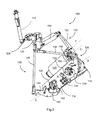
- the first haptic system 108 is shown comprising the first handpiece 112.
- the first haptic system 108 comprises a frame 116 mounted to the housing 101.
- a first, second and third motor 118, 120, 122 are mounted to the housing 116.
- the first and second motors 118, 120 have parallel and offset output axes A, B with the third motor 122 having an axis C perpendicular to the axes A and B.
- the first handpiece 112 (to be described) is mounted on a gimbal 124 for rotation in three degrees of freedom.
- the gimbal 124 is mounted to a handpiece mount 125 in the shape of an inverted "L".
- the handpiece mount 125 is driven in three dimensional space 116 by a first, second and third linkage 126, 128, 130.
- the first linkage 126 comprises a crank 132 extending radially from the output of the first motor 118.
- the crank 126 is connected at a position spaced from the motor to a first link 134.
- the first link 134 is connected to a second link 136 pivoted to the frame 116 about a second link axis D (parallel to axis A).
- the second link 136 is connected to a first pushrod 138.
- the first pushrod 138 is connected to the handpiece mount 125.
- the second linkage 128 comprises a crank 140 extending radially from the output of the second motor 120.
- the crank 140 is connected at a position spaced from the motor to a third link 142.
- the third link 142 is connected to a fourth link 144 pivoted to the frame 116 about a fourth link axis E (parallel to axis B).
- the fourth link 144 is connected to a second pushrod 146.
- the second pushrod 146 is connected to the handpiece mount 125.
- the third linkage 130 comprises a crank 148 extending radially from the output of the third motor 122.
- the crank 148 is connected at a position spaced from the motor to a fifth link 150.
- the fifth link 150 is connected to a sixth link 152 pivoted to the frame 116 about a sixth link axis F (parallel to axis C).
- the sixth link 152 is connected to a third pushrod 154.
- the third pushrod 154 is connected to the handpiece mount 125.
- the first, second and third pushrods 138, 146, 154 are oriented perpendicular to one another, and are arranged to move axially along their lengths in response to actuation of the respective motors 118, 120 ,122 respectively.
- the global linear position of the gimbal mount 125, the gimbal 124 and hence the handpiece 112 is a function of the rotation of the motors 118, 120, 112.
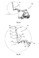
- the first handpiece 112 comprises a generally cylindrical body 194 extending from a first end 196 where the handpiece 112 is connected to the gimbal 124 to a second end 198.
- a first tool formation 200 comprising a pair of resiliently biased wings 202 configured to simulate the action of a pair of forceps.
- the wings 202 are connected to a force transducer to provide a signal indicating the degree of actuation for the computer 102.
- a second tool formation 204 in the form of a syringe plunger 206.
- the plunger 206 is not movable in the body 194, but is connected to a force transducer to provide a signal indicating applied force for the computer 102.
- the first handpiece 112 is connected to the computer 102 by a four conductor data wire 222. This is shown schematically in Figure 1 , and also in Figure 3b .
- Each of the tool formations 200, 204 are configured such that the respective force sensor produces a data signal for transmission along the wire 222.
- the data signals use the Inter-Integrated Circuit (I 2 C) protocol enabling serial transmission of multiple signals.
- I 2 C Inter-Integrated Circuit
- the gimbal 124 comprises a first gimbal member 208 extending from the gimbal mount 125.
- the first gimbal member 208 has a first end 210 and a second end 212.
- the first gimbal member 208 is generally elongate and is mounted to the gimbal mount 125 at its first end 210 by a first gimbal joint 214 for rotation about its main axis, and local rotation degree of freedom LY.
- the second end 212 of the gimbal member 208 is connected to the first end 196 of the handpiece 112 via a second gimbal joint 216 having local rotational degree of freedom LX.
- the body 196 defines an integral rotational joint 218 having local rotational degree of freedom LZ.
- the handpiece 112 is configured for free rotation in three local degrees of freedom LX, LY and LZ. None of the joints are powered, or have encoders therein- the gimbal 124 and joints 214, 216, 218 can therefore be made very small as shown.
- an inertial measurement unit (IMU) 220 is positioned within the body 194 of the handpiece 112.
- the IMU 220 is configured to measure translational acceleration, rotational velocities and the magnetic field.
- the IMU is also capable of determining the speed and displacement of the handpiece 112 using data processing techniques known in the art.
- the IMU 220 is assembled with a microchip (not shown) configured to convert the data output from the IMU into a digital Inter-Integrated Circuit (I 2 C). This data output is passed along the wire 222 along with the signals from the tool formations 200, 204 to the computer 102.
- the computer 102 is configured to:
- a control scheme is used in which the position, orientation and actuation of the handpiece 112 is known by the computer 102, which is also able to provide haptic feedback to the handpiece 112 via the motors as determined by the characteristics of the virtual model.
- the position of the virtual tools within the virtual environment is displayed on the VDU 104.
- the position of the virtual tools within the virtual environment is displayed on the VDU 104.
- the second haptic system 110 is similar to the first haptic system 108 and as such will not be described in detail here.
- the data link 222 may be a wireless link, using e.g. bluetooth.
- the IMU may be of any type which is capable of measuring motion, position and / or orientation.
- the IMU may measure only accelerations using numerical methods to determine velocity and displacement.
Landscapes
- Engineering & Computer Science (AREA)
- Physics & Mathematics (AREA)
- General Physics & Mathematics (AREA)
- Theoretical Computer Science (AREA)
- Business, Economics & Management (AREA)
- Educational Administration (AREA)
- Educational Technology (AREA)
- Chemical & Material Sciences (AREA)
- Health & Medical Sciences (AREA)
- General Health & Medical Sciences (AREA)
- Medical Informatics (AREA)
- Medicinal Chemistry (AREA)
- Algebra (AREA)
- Computational Mathematics (AREA)
- Mathematical Analysis (AREA)
- Mathematical Optimization (AREA)
- Mathematical Physics (AREA)
- Pure & Applied Mathematics (AREA)
- Dental Tools And Instruments Or Auxiliary Dental Instruments (AREA)
Priority Applications (6)
| Application Number | Priority Date | Filing Date | Title |
|---|---|---|---|
| EP14181949.0A EP2988288A1 (fr) | 2014-08-22 | 2014-08-22 | Pièce à main de simulateur médical |
| PCT/EP2015/068868 WO2016026818A1 (fr) | 2014-08-22 | 2015-08-17 | Pièce à main de simulateur médical |
| CA2958836A CA2958836A1 (fr) | 2014-08-22 | 2015-08-17 | Piece a main de simulateur medical |
| US15/503,731 US20170278427A1 (en) | 2014-08-22 | 2015-08-17 | Medical simulator handpiece |
| CN201580044619.5A CN106575485A (zh) | 2014-08-22 | 2015-08-17 | 医疗模拟器手持件 |
| IL250698A IL250698A0 (en) | 2014-08-22 | 2017-02-21 | Manual part for medical simulator |
Applications Claiming Priority (1)
| Application Number | Priority Date | Filing Date | Title |
|---|---|---|---|
| EP14181949.0A EP2988288A1 (fr) | 2014-08-22 | 2014-08-22 | Pièce à main de simulateur médical |
Publications (1)
| Publication Number | Publication Date |
|---|---|
| EP2988288A1 true EP2988288A1 (fr) | 2016-02-24 |
Family
ID=51398505
Family Applications (1)
| Application Number | Title | Priority Date | Filing Date |
|---|---|---|---|
| EP14181949.0A Ceased EP2988288A1 (fr) | 2014-08-22 | 2014-08-22 | Pièce à main de simulateur médical |
Country Status (6)
| Country | Link |
|---|---|
| US (1) | US20170278427A1 (fr) |
| EP (1) | EP2988288A1 (fr) |
| CN (1) | CN106575485A (fr) |
| CA (1) | CA2958836A1 (fr) |
| IL (1) | IL250698A0 (fr) |
| WO (1) | WO2016026818A1 (fr) |
Cited By (2)
| Publication number | Priority date | Publication date | Assignee | Title |
|---|---|---|---|---|
| GB2548341A (en) * | 2016-03-10 | 2017-09-20 | Moog Bv | Movement tracking and simulation device and method |
| WO2022002778A1 (fr) | 2020-07-02 | 2022-01-06 | Simtolife B.V. | Appareils et mécanismes pour la simulation d'interventions et de procédés dentaires |
Families Citing this family (6)
| Publication number | Priority date | Publication date | Assignee | Title |
|---|---|---|---|---|
| US10810907B2 (en) | 2016-12-19 | 2020-10-20 | National Board Of Medical Examiners | Medical training and performance assessment instruments, methods, and systems |
| US10610303B2 (en) * | 2017-06-29 | 2020-04-07 | Verb Surgical Inc. | Virtual reality laparoscopic tools |
| EP3793465A4 (fr) | 2018-05-18 | 2022-03-02 | Auris Health, Inc. | Dispositifs de commande pour systèmes télécommandés à activation robotique |
| NL2021329B1 (en) * | 2018-07-17 | 2020-01-24 | Vitestro Holding B V | Cannula insertion system |
| NL2022350B1 (en) | 2019-01-07 | 2020-08-13 | Vitestro Holding B V | Cannula insertion system |
| NL2022351B1 (en) | 2019-01-07 | 2020-08-13 | Vitestro Holding B V | Contact sensor positioning system, cannula insertion system and method to position a contact sensor |
Citations (4)
| Publication number | Priority date | Publication date | Assignee | Title |
|---|---|---|---|---|
| WO1998019222A1 (fr) * | 1996-10-25 | 1998-05-07 | Immersion Human Interface Corporation | Interface mecanique comportant plusieurs dispositifs d'actionnement fixes au sol |
| WO2005096249A1 (fr) * | 2004-03-23 | 2005-10-13 | Laerdal Medical Corporation | Systeme de simulation d'acces vasculaire a effecteur terminal externe |
| US7821496B2 (en) * | 1995-01-18 | 2010-10-26 | Immersion Corporation | Computer interface apparatus including linkage having flex |
| US8716973B1 (en) * | 2011-02-28 | 2014-05-06 | Moog Inc. | Haptic user interface |
Family Cites Families (9)
| Publication number | Priority date | Publication date | Assignee | Title |
|---|---|---|---|---|
| JP2001504605A (ja) * | 1996-08-14 | 2001-04-03 | ラティポフ,ヌラフメド,ヌリスラモビチ | 空間内のユーザの位置及び方向性を追跡及び表示するための方法、ユーザに対し仮想環境を提示するための方法及びこれらの方法を実現するためのシステム |
| WO2007002079A2 (fr) * | 2005-06-21 | 2007-01-04 | Traxtal Inc. | Système, procédé et appareil pour thérapie et diagnostic avec navigation |
| US20070190484A1 (en) * | 2006-02-10 | 2007-08-16 | Dentsply International Inc. | Closed loop speed control for a pneumatic dental handpiece |
| US20070270686A1 (en) * | 2006-05-03 | 2007-11-22 | Ritter Rogers C | Apparatus and methods for using inertial sensing to navigate a medical device |
| EP2496155B1 (fr) * | 2009-09-13 | 2016-04-20 | Trig Medical Ltd. | Dispositif d'accouchement à capteur de position |
| US20130303860A1 (en) * | 2011-11-21 | 2013-11-14 | Robert Bender | Systems and methods for use in fall risk assessment |
| US9679199B2 (en) * | 2013-12-04 | 2017-06-13 | Microsoft Technology Licensing, Llc | Fusing device and image motion for user identification, tracking and device association |
| EP3034991B2 (fr) * | 2014-12-19 | 2022-08-24 | Hexagon Technology Center GmbH | Procédé et dispositif de compensation des forces de déplacement avec une unité de sonde |
| US11511156B2 (en) * | 2016-03-12 | 2022-11-29 | Arie Shavit | Training system and methods for designing, monitoring and providing feedback of training |
-
2014
- 2014-08-22 EP EP14181949.0A patent/EP2988288A1/fr not_active Ceased
-
2015
- 2015-08-17 WO PCT/EP2015/068868 patent/WO2016026818A1/fr not_active Ceased
- 2015-08-17 CA CA2958836A patent/CA2958836A1/fr not_active Abandoned
- 2015-08-17 US US15/503,731 patent/US20170278427A1/en not_active Abandoned
- 2015-08-17 CN CN201580044619.5A patent/CN106575485A/zh active Pending
-
2017
- 2017-02-21 IL IL250698A patent/IL250698A0/en unknown
Patent Citations (4)
| Publication number | Priority date | Publication date | Assignee | Title |
|---|---|---|---|---|
| US7821496B2 (en) * | 1995-01-18 | 2010-10-26 | Immersion Corporation | Computer interface apparatus including linkage having flex |
| WO1998019222A1 (fr) * | 1996-10-25 | 1998-05-07 | Immersion Human Interface Corporation | Interface mecanique comportant plusieurs dispositifs d'actionnement fixes au sol |
| WO2005096249A1 (fr) * | 2004-03-23 | 2005-10-13 | Laerdal Medical Corporation | Systeme de simulation d'acces vasculaire a effecteur terminal externe |
| US8716973B1 (en) * | 2011-02-28 | 2014-05-06 | Moog Inc. | Haptic user interface |
Non-Patent Citations (5)
| Title |
|---|
| "Experimental Robotics V", vol. 232, 1 January 1998, SPRINGER BERLIN HEIDELBERG, Berlin, Heidelberg, ISBN: 978-3-54-040920-5, ISSN: 0170-8643, article V. HAYWARD ET AL: "Freedom-7: A high fidelity seven axis haptic device with application to surgical training", pages: 443 - 456, XP055164235, DOI: 10.1007/BFb0112983 * |
| INTELLIGENTHUMAN-COMPUTER-INTERACTION SS2011 GABRIELEBLESER ET AL: "Principlesofinertialsensingtechnology anditsapplicationsinIHCI Motivation", 1 January 2011 (2011-01-01), XP055629478, Retrieved from the Internet <URL:https://ags.cs.uni-kl.de/fileadmin/inf_ags/ihci-ss11/IHCI_SS11_lec08.pdf> [retrieved on 20191007] * |
| KAI BIERMANN ET AL: "Mächtige Sensoren", 28 May 2014 (2014-05-28), XP055629542, Retrieved from the Internet <URL:https://www.zeit.de/digital/mobil/2014-05/smartphone-sensoren-iphone-samsung> [retrieved on 20191007] * |
| MASSIMILIANO ZECCA ET AL: "Development of the Ultra-Miniaturized Inertial Measurement Unit WB3 for Objective Skill Analysis and Assessment in Neurosurgery: Preliminary Results", 20 September 2009, MEDICAL IMAGE COMPUTING AND COMPUTER-ASSISTED INTERVENTION - MICCAI 2009, SPRINGER BERLIN HEIDELBERG, BERLIN, HEIDELBERG, PAGE(S) 443 - 450, ISBN: 978-3-642-04267-6, XP019130350 * |
| SANDRO F QUEIROS ET AL: "A laparoscopic surgery training interface", SERIOUS GAMES AND APPLICATIONS FOR HEALTH (SEGAH), 2011 IEEE 1ST INTERNATIONAL CONFERENCE ON, IEEE, 16 November 2011 (2011-11-16), pages 1 - 7, XP032127598, ISBN: 978-1-4673-0433-7, DOI: 10.1109/SEGAH.2011.6165446 * |
Cited By (4)
| Publication number | Priority date | Publication date | Assignee | Title |
|---|---|---|---|---|
| GB2548341A (en) * | 2016-03-10 | 2017-09-20 | Moog Bv | Movement tracking and simulation device and method |
| WO2022002778A1 (fr) | 2020-07-02 | 2022-01-06 | Simtolife B.V. | Appareils et mécanismes pour la simulation d'interventions et de procédés dentaires |
| CN115812229A (zh) * | 2020-07-02 | 2023-03-17 | 斯密托利弗私人有限公司 | 用于模拟牙科手术和方法的装置和机构 |
| CN115812229B (zh) * | 2020-07-02 | 2025-11-14 | 斯密托利弗私人有限公司 | 用于模拟牙科手术和方法的装置和机构 |
Also Published As
| Publication number | Publication date |
|---|---|
| IL250698A0 (en) | 2017-04-30 |
| CN106575485A (zh) | 2017-04-19 |
| CA2958836A1 (fr) | 2016-02-25 |
| US20170278427A1 (en) | 2017-09-28 |
| WO2016026818A1 (fr) | 2016-02-25 |
Similar Documents
| Publication | Publication Date | Title |
|---|---|---|
| EP2988288A1 (fr) | Pièce à main de simulateur médical | |
| CN211827846U (zh) | 医疗模拟系统 | |
| US9092996B2 (en) | Microsurgery simulator | |
| GB2589458A (en) | A virtual reality surgical system including a surgical tool assembly with haptic feedback | |
| RU2741469C1 (ru) | Роботизированная хирургическая система | |
| CN101978243A (zh) | 跟踪系统和方法 | |
| CN110177518A (zh) | 用于在图像捕获装置的视场内检测物体的系统和方法 | |
| US12354492B2 (en) | Vibrotactile method, apparatus and system for training and practicing dental procedures | |
| US10388187B2 (en) | Medical simulator handpiece | |
| CN115812229B (zh) | 用于模拟牙科手术和方法的装置和机构 | |
| EP2988289A1 (fr) | Simulateur de procédure médicale | |
| EP4010893B1 (fr) | Appareils pour la simulation de procédures dentaires et procédés | |
| US20230149085A1 (en) | Surgical simulation device | |
| KR20220069604A (ko) | 안구 운동 모사 시스템, 방법, 및 상기 방법을 실행시키기 위한 컴퓨터 판독 가능한 프로그램을 기록한 기록 매체 | |
| DK180682B1 (en) | Apparatus for simulating medical procedures and methods | |
| Beier | The integration of a neurosurgical microscope as an interface to a medical training simulator | |
| Watanabe et al. | A reconfigurable master device for a modular surgical robot and evaluation of its feasibility |
Legal Events
| Date | Code | Title | Description |
|---|---|---|---|
| PUAI | Public reference made under article 153(3) epc to a published international application that has entered the european phase |
Free format text: ORIGINAL CODE: 0009012 |
|
| AK | Designated contracting states |
Kind code of ref document: A1 Designated state(s): AL AT BE BG CH CY CZ DE DK EE ES FI FR GB GR HR HU IE IS IT LI LT LU LV MC MK MT NL NO PL PT RO RS SE SI SK SM TR |
|
| AX | Request for extension of the european patent |
Extension state: BA ME |
|
| 17P | Request for examination filed |
Effective date: 20160810 |
|
| RBV | Designated contracting states (corrected) |
Designated state(s): AL AT BE BG CH CY CZ DE DK EE ES FI FR GB GR HR HU IE IS IT LI LT LU LV MC MK MT NL NO PL PT RO RS SE SI SK SM TR |
|
| STAA | Information on the status of an ep patent application or granted ep patent |
Free format text: STATUS: EXAMINATION IS IN PROGRESS |
|
| 17Q | First examination report despatched |
Effective date: 20170921 |
|
| TPAC | Observations filed by third parties |
Free format text: ORIGINAL CODE: EPIDOSNTIPA |
|
| STAA | Information on the status of an ep patent application or granted ep patent |
Free format text: STATUS: THE APPLICATION HAS BEEN REFUSED |
|
| 18R | Application refused |
Effective date: 20200320 |