EP2988314A1 - Maillon fusible multipolaire - Google Patents
Maillon fusible multipolaire Download PDFInfo
- Publication number
- EP2988314A1 EP2988314A1 EP14785881.5A EP14785881A EP2988314A1 EP 2988314 A1 EP2988314 A1 EP 2988314A1 EP 14785881 A EP14785881 A EP 14785881A EP 2988314 A1 EP2988314 A1 EP 2988314A1
- Authority
- EP
- European Patent Office
- Prior art keywords
- fusible
- multipolar
- bus bar
- height
- fusible link
- Prior art date
- Legal status (The legal status is an assumption and is not a legal conclusion. Google has not performed a legal analysis and makes no representation as to the accuracy of the status listed.)
- Granted
Links
Images


Classifications
-
- H—ELECTRICITY
- H01—ELECTRIC ELEMENTS
- H01H—ELECTRIC SWITCHES; RELAYS; SELECTORS; EMERGENCY PROTECTIVE DEVICES
- H01H85/00—Protective devices in which the current flows through a part of fusible material and this current is interrupted by displacement of the fusible material when this current becomes excessive
- H01H85/02—Details
- H01H85/04—Fuses, i.e. expendable parts of the protective device, e.g. cartridges
- H01H85/05—Component parts thereof
- H01H85/055—Fusible members
- H01H85/08—Fusible members characterised by the shape or form of the fusible member
-
- H—ELECTRICITY
- H01—ELECTRIC ELEMENTS
- H01H—ELECTRIC SWITCHES; RELAYS; SELECTORS; EMERGENCY PROTECTIVE DEVICES
- H01H1/00—Contacts
- H01H1/58—Electric connections to or between contacts; Terminals
-
- H—ELECTRICITY
- H01—ELECTRIC ELEMENTS
- H01H—ELECTRIC SWITCHES; RELAYS; SELECTORS; EMERGENCY PROTECTIVE DEVICES
- H01H85/00—Protective devices in which the current flows through a part of fusible material and this current is interrupted by displacement of the fusible material when this current becomes excessive
- H01H85/02—Details
- H01H85/04—Fuses, i.e. expendable parts of the protective device, e.g. cartridges
- H01H85/05—Component parts thereof
- H01H85/055—Fusible members
- H01H85/08—Fusible members characterised by the shape or form of the fusible member
- H01H85/10—Fusible members characterised by the shape or form of the fusible member with constriction for localised fusing
-
- H—ELECTRICITY
- H01—ELECTRIC ELEMENTS
- H01H—ELECTRIC SWITCHES; RELAYS; SELECTORS; EMERGENCY PROTECTIVE DEVICES
- H01H85/00—Protective devices in which the current flows through a part of fusible material and this current is interrupted by displacement of the fusible material when this current becomes excessive
- H01H85/02—Details
- H01H85/04—Fuses, i.e. expendable parts of the protective device, e.g. cartridges
- H01H85/05—Component parts thereof
- H01H85/055—Fusible members
- H01H85/12—Two or more separate fusible members in parallel
-
- H—ELECTRICITY
- H01—ELECTRIC ELEMENTS
- H01H—ELECTRIC SWITCHES; RELAYS; SELECTORS; EMERGENCY PROTECTIVE DEVICES
- H01H85/00—Protective devices in which the current flows through a part of fusible material and this current is interrupted by displacement of the fusible material when this current becomes excessive
- H01H85/02—Details
- H01H85/04—Fuses, i.e. expendable parts of the protective device, e.g. cartridges
- H01H85/05—Component parts thereof
- H01H85/055—Fusible members
- H01H2085/0555—Input terminal connected to a plurality of output terminals, e.g. multielectrode
-
- H—ELECTRICITY
- H01—ELECTRIC ELEMENTS
- H01H—ELECTRIC SWITCHES; RELAYS; SELECTORS; EMERGENCY PROTECTIVE DEVICES
- H01H85/00—Protective devices in which the current flows through a part of fusible material and this current is interrupted by displacement of the fusible material when this current becomes excessive
- H01H85/02—Details
- H01H85/04—Fuses, i.e. expendable parts of the protective device, e.g. cartridges
- H01H85/05—Component parts thereof
- H01H85/143—Electrical contacts; Fastening fusible members to such contacts
- H01H85/153—Knife-blade-end contacts
Definitions
- the invention in this application relates to a multipolar fusible link to be used mainly for, for example, an electric circuit in an automobile.
- a multipolar fusible link 200 known in the art includes: as main components, an input terminal 210; a bus bar 220 having a substantially rectangular shape in a planar view through which an electric current input from the input terminal 210 flows; and a plurality of terminals (240A to 240D) connected to the bus bar 220 via fusible sections (230A to 230D).
- the input terminal 210 in the multipolar fusible link 200 is connected to a battery or some other power source, whereas the terminals (240A to 240D) are connected to various electrical instruments. In this way, a configuration in which fuses are provided between the battery or power source and the electric circuits in the electrical instruments is created. If an unexpected high current flows through one of the electric circuits, the corresponding fusible section 230 is heated and blown by the high current, protecting this electrical instrument against overcurrent that would flow through it.
- the multipolar fusible link 200 is provided with the fusible sections 230 having different ratings which are connected between the plurality of terminals 240 and the bus bar 220.
- the fusible section 230A having a rating of 50 A (amperes), which is positioned close to the input terminal 210, is connected to the bus bar 220
- the three fusible sections 230B to 230D each having a rating of 40 A, which are positioned adjacent to the fusible section 230A, are sequentially connected to the bus bar 220.
- the ratings of the fusible sections are depicted over the terminals 240 to which these fusible sections are connected, for the sake of convenience.
- the fusible section 230E having a rating of 40 A has a shape in which three arms (arms 1, 2, and 3) are interconnected with two links (links 1 and 2). It can be found that the entire length of a fusible section 230E is greater than that of the fusible section 230A having a rating of 50 A illustrated in Fig. 4(a) .
- an angle ⁇ (refer to Fig. 4(b) ) between the arms needs to be changed into a smaller angle ⁇ 1 without changing the entire length of the fusible section (i.e., without changing the lengths of the arms). It can be found that a height H ⁇ 1 (see Fig. 4(c) ) of a fusible section 230E' with the angle ⁇ 1 is less than a height H ⁇ (see Fig. 4(b) ) of the fusible section 230E with the angle ⁇ .
- the shapes of the fusible sections 230B to 230D are changed into the shape of the fusible section 230E' with the height H ⁇ 1 illustrated in Fig. 4(c) .
- c0 denotes the height of the bus bar 220
- d0 denotes the height of the terminals 240 (the height of all the terminals 240A to 240D is equal to d0).
- the angle between the arms has a lower limit that is dependent on design specifications.
- the angle between the arms in a fusible section cannot be decreased to less than ⁇ 1, for convenience of explanation.
- the angle between the arms is set to ⁇ 1, the height H ⁇ 1 of the fusible section can no longer be decreased.
- the invention in this application has been made in light of the above problem with an object of providing a multipolar fusible link that is less dependent on a trade-off between its entire height and lateral width and thus has a higher degree of design flexibility in the entire height and lateral width.
- a multipolar fusible link of the invention in this application includes: an input terminal; a bus bar through which an electric current input from the input terminal flows; and a plurality of terminals connected to the bus bar via fusible sections.
- the width between the lower and upper edges of the bus bar in a height direction (referred to below as “the height of the bus bar” for the sake of simplification) is changed in accordance with the change in the shape of the lower edge. More specifically, the height of the bus bar is decreased in accordance with the change in the shape of the lower edge.
- the decrease in the height of the bus bar enables a larger space to be reserved on the side of the lower edge. This space allows for a change in the shape of a fusible section connected to the lower edge. As a result of changing the shape of the fusible section so that its lateral width decreases, the overall lateral width of the multipolar fusible link including this fusible section decreases.
- the multipolar fusible link can have a smaller overall height than an existing multipolar fusible link.
- the multipolar fusible link of the invention in this application configured above can be small in overall height and in overall lateral width.
- the multipolar fusible link can be installed inside a compact fuse box.
- the multipolar fusible link is formed by stamping a conductive metal piece. Therefore, a lot more multipolar fusible links, which are small in overall height and in overall lateral width, can be fabricated from a single metal plate. This results in the enhancement of the fabrication yield.
- the shapes of the fusible sections connected to the lower edge can be changed into any given shapes within a space on the side of the lower edge which is created as a result of decreasing the height of the bus bar.
- the shape of a fusible section may be changed as appropriate so that the lateral width of the multipolar fusible link including this fusible section decreases while the height thereof is maintained as it is, or so that the height of the multipolar fusible link including this fusible section decreases while the lateral width thereof is maintained as it is.
- the multipolar fusible link of the invention in this application is characterized in that the shape of the lower edge of the bus bar is changed so that the width between the lower and upper edges of the bus bar decreases from the input terminal toward an end edge positioned opposite the input terminal.
- the width of the bus bar in a height direction (referred to below as “the height of the bus bar” for the sake of simplification) can be changed in accordance with the decrease in the current flow. More specifically, the end edge positioned opposite the input terminal can be formed so as to be smaller in width than the input terminal. In this way, the height of the bus bar can be optimized in accordance with a current flowing through it.
- the end edge of the bus bar can be smaller in height than the input terminal, a larger space for changing the shapes of the fusible sections are reserved toward the end edge. Therefore, the shape of a fusible section connected closer to the end edge can be changed so that its lateral width becomes smaller. This results in the decrease in the overall lateral width of the multipolar fusible link.
- a multipolar fusible link, as described above, of the invention in this application is less dependent on a trade-off between its entire height and lateral width and thus has a higher degree of design flexibility in the entire height and lateral width.
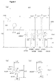
- Fig. 1 illustrates a multipolar fusible link 100 of the invention in this application.
- This multipolar fusible link 100 includes: an input terminal 110; a bus bar 120; fusible sections 130 connected to a lower edge 122 of the bus bar 120; and terminals 140 via the corresponding fusible sections 130.
- the arrangement sequence of the fusible sections 130 is the same as that of an existing multipolar fusible link 200 (see Fig. 4(a) ). More specifically, a fusible section 130A having a rating of 50A (ampere) is connected close to the input terminal 110, and three fusible sections 130B to 130D each having a rating of 40A are sequentially connected next to the fusible section 130A.
- the fusible sections 130B to 130D have different angles between the arms from fusible sections 230B to 230D, respectively, in the existing multipolar fusible link 200, but their entire lengths (arm lengths) are the same.
- the height of the bus bar 120 is nonuniform as opposed to the existing bus bar 220 (see Fig. 4(a) ). More specifically, it decreases toward an end edge 123. A reason why the height of the bus bar 120 is changed in this manner will be described below briefly.
- An electric current that flows through the multipolar fusible link 100 is first input to the input terminal 110 and then flows through the bus bar 120 toward the end edge 123.
- parts of the current branch off and flow into the terminals 140 via the corresponding fusible sections 130. More specifically, suppose a current of 170 A is input to the input terminal 110. Then, while this current is flowing from the input terminal 110 toward the end edge 123, a current of 50 A branches off from the current and flows into the fusible section 130A. As a result, the current that flows from a point A toward the end edge 123 is equal to 120 A, which is decreased by the branch current of 50A.
- the height of the bus bar 120 at a location closer to the end edge 123 than the point A can be a height b1, which is less than the height c0 and proportional to the current of 120 A flowing at this location.
- the shape of the lower edge 122 can be changed into an inclined shape such that the height between the upper edge 121 and the lower edge 122 decreases.
- the current flowing toward the end edge 123 is equal to 80A, which is decreased by a branch current of 40 A flowing into the fusible section 130B.
- the height of the bus bar 120 at a location closer to the end edge 123 than the point B can be a height b2, which is less than the height b1 and proportional to the current of 80 A flowing at this location.
- the height of the bus bar 120 becomes the minimum, or a height b3. In this way, the height of the bus bar 120 can be optimized such that it gradually decreases in proportion to a current flowing through it.
- the height of the bus bar 120 gradually decreases to b1, b2, and b3. This enables a gradually increasing space S for arranging the fusible sections (130B to 130D) to be reserved on the lower edge 122 of the bus bar 120.
- the multipolar fusible link 100 does not become greater in the overall height than an existing one, as will be described later.
- the angle between the arms of the fusible section 130B is set to ⁇ 1, which can no longer be decreased; and the height of the fusible section 130B is set to H ⁇ 1, which is the minimum value.
- the lower edge of a bus bar is linearly inclined such that the height thereof decreases.
- the shape of a bus bar and its height may be changed differently.
- the height of a bus bar may decrease in stages.
- Fig. 2 illustrates the fusible sections 130B to 130D of the multipolar fusible link 100 in Fig. 1 in an enlarged manner.
- the height of the fusible section 130B is denoted by H ⁇ 1
- the lateral width thereof is denoted by L ⁇ 1.
- the lower edge 122 is inclined toward the end edge 123 while the height of the bus bar 120 gradually decreases. So, the space reserved in a height direction to form the adjacent fusible section 130C has a height H ⁇ 2, which is greater than the height H ⁇ 1 of the fusible section 130B. Therefore, the shape of the fusible section 130C can be changed so that it expands vertically (or so that the angle ⁇ 2 between the arms becomes greater than the angle ⁇ 1).
- a lateral width L ⁇ 2 of the fusible section 130C becomes smaller than the lateral width L ⁇ 1 of the fusible section 130B.
- the height of the bus bar 120 is further decreased at the location of the fusible section 130D formed adjacent to the fusible section 130C, whereby the space secured in a height direction to form the fusible section 130D has a height H ⁇ 3, which is greater than the height H ⁇ 2. Therefore, the shape of the fusible section 130D can be changed so that it expands vertically (or so that the angle between the arms becomes ⁇ 3 that is greater than the angle ⁇ 2). Thus, a lateral width L ⁇ 3 of the fusible section 130D becomes smaller than the lateral width L ⁇ 2 of the fusible section 130C.
- the space S for arranging the fusible sections can be reserved in a height direction and the shapes of the fusible sections can be changed so that their lateral widths decrease. Consequently, it is possible to not only make the height H1 of the multipolar fusible link 100 in this application less than that of the existing multipolar fusible link 200 but also make the lateral width W1 of the multipolar fusible link 100 smaller than that of the existing multipolar fusible link 200. In other words, it is possible to decrease the lateral width of a multipolar fusible link without increasing its overall height, as opposed to an existing one.
- the four fusible sections 130A to 130D are connected to the bus bar 120, but there is no limitation on the number of fusible sections. It should be understood that a lot more fusible sections can be connected. Also if a larger number of fusible sections are connected, the shape of a fusible section positioned closer to an end edge can be changed more greatly so that its lateral width decreases. This is because a larger space for arranging fusible sections is reserved in a height direction toward the end edge. Therefore, a multipolar fusible link in this application is more effective in decreasing its overall lateral width than an existing multipolar fusible link, especially when they have the same number of fusible sections.
- Fig. 3 illustrates an aspect in which an insulating housing is attached to a multipolar fusible link of the invention in this application.
- a multipolar fusible link 100 is formed by stamping a metal plate into a shape as illustrated in Fig. 3(a) , so that a bus bar 120, fusible sections 130, and terminals 140 are formed integrally.
- the metal plate may be made of a conducting metal such as copper. It should be noted that the bus bar 120, the fusible section 130, and the terminal 140 do not necessarily have to be formed integrally by stamping a single place. Alternatively, these members may be prepared separately and welded to one another.
- an insulating housing H made of, for example, an insulating synthetic resin is attached to the multipolar fusible link 100 so as to sandwich it from the upper and lower sides.
- the input terminal 110 and the terminal 140 in the multipolar fusible link 100 are, however, exposed so that they can be connected to a fuse box and the like.
- the insulating housing H has a transparent window W that covers the fusible sections 130, allowing the fusible section 130 to be viewed from the outside.
- the multipolar fusible link 100 to which the insulating housing H is attached is installed inside, for example, a fuse box and then is used.
- a multipolar fusible link of the invention in this application is not limited to the examples described above and can undergo various modifications and combinations within the scope of the claims and embodiments. Such modifications and combinations should be included within the scope of the patent right.
- multipolar fusible link of the invention in this application are not limited to electric circuits in automobiles.
- This multipolar fusible link can be used as fuses for different types of electric circuits, and obviously such fuses should also be included within the technical scope of the invention.
Landscapes
- Physics & Mathematics (AREA)
- Electromagnetism (AREA)
- Fuses (AREA)
Applications Claiming Priority (3)
| Application Number | Priority Date | Filing Date | Title |
|---|---|---|---|
| JP2013086363A JP5903399B2 (ja) | 2013-04-17 | 2013-04-17 | 多極型ヒュージブルリンク |
| JP2013149288A JP5903407B2 (ja) | 2013-07-18 | 2013-07-18 | 多極型ヒュージブルリンク |
| PCT/JP2014/001682 WO2014171074A1 (fr) | 2013-04-17 | 2014-03-25 | Maillon fusible multipolaire |
Publications (3)
| Publication Number | Publication Date |
|---|---|
| EP2988314A1 true EP2988314A1 (fr) | 2016-02-24 |
| EP2988314A4 EP2988314A4 (fr) | 2016-12-28 |
| EP2988314B1 EP2988314B1 (fr) | 2019-08-28 |
Family
ID=51731038
Family Applications (1)
| Application Number | Title | Priority Date | Filing Date |
|---|---|---|---|
| EP14785881.5A Active EP2988314B1 (fr) | 2013-04-17 | 2014-03-25 | Maillon fusible multipolaire |
Country Status (5)
| Country | Link |
|---|---|
| US (1) | US9754754B2 (fr) |
| EP (1) | EP2988314B1 (fr) |
| KR (1) | KR102119699B1 (fr) |
| CN (1) | CN105103260B (fr) |
| WO (1) | WO2014171074A1 (fr) |
Cited By (1)
| Publication number | Priority date | Publication date | Assignee | Title |
|---|---|---|---|---|
| SE2450871A1 (en) * | 2024-08-28 | 2026-03-01 | Traton Ab | Busbar current interruption device, battery module, battery pack, and vehicle |
Families Citing this family (7)
| Publication number | Priority date | Publication date | Assignee | Title |
|---|---|---|---|---|
| CN111226302B (zh) * | 2017-10-19 | 2022-12-20 | 沃尔沃卡车集团 | 保险丝盒、包括这种保险丝盒的保险丝盒组件和车辆 |
| DE102017222642A1 (de) * | 2017-12-13 | 2019-06-27 | Bayerische Motoren Werke Aktiengesellschaft | Elektrochemisches energiespeichermodul und fahrzeug |
| KR102505612B1 (ko) | 2018-01-31 | 2023-03-03 | 삼성에스디아이 주식회사 | 배터리 팩 |
| JP2018088418A (ja) * | 2018-02-05 | 2018-06-07 | 太平洋精工株式会社 | 多極型ヒュージブルリンクに取り付けられるハウジング、ヒューズ、及びヒューズボックス |
| JP6947139B2 (ja) * | 2018-08-29 | 2021-10-13 | 株式会社オートネットワーク技術研究所 | 過電流遮断ユニット |
| KR102598669B1 (ko) * | 2018-09-11 | 2023-11-06 | 에스케이온 주식회사 | 버스 바 및 이를 구비하는 배터리 팩 |
| US10581611B1 (en) | 2018-10-02 | 2020-03-03 | Capital One Services, Llc | Systems and methods for cryptographic authentication of contactless cards |
Family Cites Families (6)
| Publication number | Priority date | Publication date | Assignee | Title |
|---|---|---|---|---|
| JPH10199396A (ja) | 1997-01-13 | 1998-07-31 | Taiheiyo Seiko Kk | 多極型ヒューズ素子およびこの素子を使用した多極型ヒューズ |
| JP3630364B2 (ja) | 2000-03-27 | 2005-03-16 | 矢崎総業株式会社 | ヒューズ構造体 |
| JP4917927B2 (ja) * | 2007-03-15 | 2012-04-18 | 太平洋精工株式会社 | 車両用多連型ヒューズ装置 |
| JP5081549B2 (ja) * | 2007-09-12 | 2012-11-28 | 矢崎総業株式会社 | 端子の接続部構造 |
| JP5771439B2 (ja) * | 2011-04-27 | 2015-08-26 | 矢崎総業株式会社 | ヒューズ回路構成体 |
| US8866256B2 (en) * | 2012-08-31 | 2014-10-21 | Fairchild Semiconductor Corporation | Unbalanced parallel circuit protection fuse device |
-
2014
- 2014-03-25 KR KR1020157027129A patent/KR102119699B1/ko active Active
- 2014-03-25 EP EP14785881.5A patent/EP2988314B1/fr active Active
- 2014-03-25 WO PCT/JP2014/001682 patent/WO2014171074A1/fr not_active Ceased
- 2014-03-25 US US14/781,478 patent/US9754754B2/en active Active
- 2014-03-25 CN CN201480016624.0A patent/CN105103260B/zh active Active
Cited By (2)
| Publication number | Priority date | Publication date | Assignee | Title |
|---|---|---|---|---|
| SE2450871A1 (en) * | 2024-08-28 | 2026-03-01 | Traton Ab | Busbar current interruption device, battery module, battery pack, and vehicle |
| SE548187C2 (en) * | 2024-08-28 | 2026-04-15 | Traton Ab | Busbar current interruption device, battery module, battery pack, and vehicle |
Also Published As
| Publication number | Publication date |
|---|---|
| KR102119699B1 (ko) | 2020-06-16 |
| US20160126048A1 (en) | 2016-05-05 |
| US9754754B2 (en) | 2017-09-05 |
| EP2988314A4 (fr) | 2016-12-28 |
| CN105103260A (zh) | 2015-11-25 |
| WO2014171074A1 (fr) | 2014-10-23 |
| EP2988314B1 (fr) | 2019-08-28 |
| KR20150143461A (ko) | 2015-12-23 |
| CN105103260B (zh) | 2018-03-16 |
Similar Documents
| Publication | Publication Date | Title |
|---|---|---|
| EP2988314B1 (fr) | Maillon fusible multipolaire | |
| US8471670B2 (en) | Fusible link unit | |
| ES2727669T3 (es) | Disposición para la distribución de corriente así como la puesta en contacto y la protección de las líneas que salen de la misma | |
| CN111095468B (zh) | 低轮廓集成熔断器模块 | |
| US9236724B2 (en) | Busbar unit | |
| US9607798B2 (en) | Fuse unit | |
| US5731944A (en) | Circuit protecting device for an automotive wiring harness | |
| US9799478B2 (en) | Fuse unit | |
| US9160154B2 (en) | Bus bar and electrical junction box having the same | |
| CN109193443A (zh) | 包括中性点连接装置的配电系统及其组装方法 | |
| US9972823B2 (en) | Fusible link | |
| CN104584177A (zh) | 熔丝单元 | |
| JP2016085939A (ja) | ヒューズ | |
| JP5903407B2 (ja) | 多極型ヒュージブルリンク | |
| EP4104197B1 (fr) | Module de fusible intégré peu encombrant | |
| JP6374912B2 (ja) | ヒュージブルリンクユニット | |
| WO2014142063A1 (fr) | Boîte à fusibles | |
| CN103682894A (zh) | 汇流条 | |
| JP5903399B2 (ja) | 多極型ヒュージブルリンク | |
| JP3165637U (ja) | 端子台 | |
| JP2009152149A (ja) | 端子台 | |
| JP6474277B2 (ja) | 3極式配電機器の分岐バーセット | |
| KR20230056918A (ko) | 멀티 퓨즈 모듈 | |
| JP2016207469A (ja) | ヒューズエレメントターミナル、及び、電気接続箱 | |
| JPH09260111A (ja) | Ptc素子による導体接続部 |
Legal Events
| Date | Code | Title | Description |
|---|---|---|---|
| PUAI | Public reference made under article 153(3) epc to a published international application that has entered the european phase |
Free format text: ORIGINAL CODE: 0009012 |
|
| 17P | Request for examination filed |
Effective date: 20151012 |
|
| AK | Designated contracting states |
Kind code of ref document: A1 Designated state(s): AL AT BE BG CH CY CZ DE DK EE ES FI FR GB GR HR HU IE IS IT LI LT LU LV MC MK MT NL NO PL PT RO RS SE SI SK SM TR |
|
| AX | Request for extension of the european patent |
Extension state: BA ME |
|
| DAX | Request for extension of the european patent (deleted) | ||
| A4 | Supplementary search report drawn up and despatched |
Effective date: 20161125 |
|
| RIC1 | Information provided on ipc code assigned before grant |
Ipc: H01H 85/10 20060101ALI20161121BHEP Ipc: H01H 85/153 20060101ALN20161121BHEP Ipc: H01H 85/12 20060101AFI20161121BHEP |
|
| REG | Reference to a national code |
Ref country code: DE Ref legal event code: R079 Ref document number: 602014052596 Country of ref document: DE Free format text: PREVIOUS MAIN CLASS: H01H0085143000 Ipc: H01H0085120000 |
|
| GRAP | Despatch of communication of intention to grant a patent |
Free format text: ORIGINAL CODE: EPIDOSNIGR1 |
|
| STAA | Information on the status of an ep patent application or granted ep patent |
Free format text: STATUS: GRANT OF PATENT IS INTENDED |
|
| RIC1 | Information provided on ipc code assigned before grant |
Ipc: H01H 85/153 20060101ALN20190319BHEP Ipc: H01H 85/12 20060101AFI20190319BHEP Ipc: H01H 85/10 20060101ALI20190319BHEP |
|
| INTG | Intention to grant announced |
Effective date: 20190418 |
|
| RIN1 | Information on inventor provided before grant (corrected) |
Inventor name: KOBAYASHI, TATSUNORI Inventor name: KAWASE, FUMIYUKI Inventor name: KIMURA, MASAHIRO |
|
| GRAS | Grant fee paid |
Free format text: ORIGINAL CODE: EPIDOSNIGR3 |
|
| GRAA | (expected) grant |
Free format text: ORIGINAL CODE: 0009210 |
|
| STAA | Information on the status of an ep patent application or granted ep patent |
Free format text: STATUS: THE PATENT HAS BEEN GRANTED |
|
| AK | Designated contracting states |
Kind code of ref document: B1 Designated state(s): AL AT BE BG CH CY CZ DE DK EE ES FI FR GB GR HR HU IE IS IT LI LT LU LV MC MK MT NL NO PL PT RO RS SE SI SK SM TR |
|
| REG | Reference to a national code |
Ref country code: GB Ref legal event code: FG4D |
|
| REG | Reference to a national code |
Ref country code: CH Ref legal event code: EP |
|
| REG | Reference to a national code |
Ref country code: DE Ref legal event code: R096 Ref document number: 602014052596 Country of ref document: DE |
|
| REG | Reference to a national code |
Ref country code: AT Ref legal event code: REF Ref document number: 1173428 Country of ref document: AT Kind code of ref document: T Effective date: 20190915 |
|
| REG | Reference to a national code |
Ref country code: IE Ref legal event code: FG4D |
|
| REG | Reference to a national code |
Ref country code: NL Ref legal event code: MP Effective date: 20190828 |
|
| REG | Reference to a national code |
Ref country code: LT Ref legal event code: MG4D |
|
| PG25 | Lapsed in a contracting state [announced via postgrant information from national office to epo] |
Ref country code: FI Free format text: LAPSE BECAUSE OF FAILURE TO SUBMIT A TRANSLATION OF THE DESCRIPTION OR TO PAY THE FEE WITHIN THE PRESCRIBED TIME-LIMIT Effective date: 20190828 Ref country code: LT Free format text: LAPSE BECAUSE OF FAILURE TO SUBMIT A TRANSLATION OF THE DESCRIPTION OR TO PAY THE FEE WITHIN THE PRESCRIBED TIME-LIMIT Effective date: 20190828 Ref country code: PT Free format text: LAPSE BECAUSE OF FAILURE TO SUBMIT A TRANSLATION OF THE DESCRIPTION OR TO PAY THE FEE WITHIN THE PRESCRIBED TIME-LIMIT Effective date: 20191230 Ref country code: HR Free format text: LAPSE BECAUSE OF FAILURE TO SUBMIT A TRANSLATION OF THE DESCRIPTION OR TO PAY THE FEE WITHIN THE PRESCRIBED TIME-LIMIT Effective date: 20190828 Ref country code: SE Free format text: LAPSE BECAUSE OF FAILURE TO SUBMIT A TRANSLATION OF THE DESCRIPTION OR TO PAY THE FEE WITHIN THE PRESCRIBED TIME-LIMIT Effective date: 20190828 Ref country code: NO Free format text: LAPSE BECAUSE OF FAILURE TO SUBMIT A TRANSLATION OF THE DESCRIPTION OR TO PAY THE FEE WITHIN THE PRESCRIBED TIME-LIMIT Effective date: 20191128 Ref country code: NL Free format text: LAPSE BECAUSE OF FAILURE TO SUBMIT A TRANSLATION OF THE DESCRIPTION OR TO PAY THE FEE WITHIN THE PRESCRIBED TIME-LIMIT Effective date: 20190828 Ref country code: BG Free format text: LAPSE BECAUSE OF FAILURE TO SUBMIT A TRANSLATION OF THE DESCRIPTION OR TO PAY THE FEE WITHIN THE PRESCRIBED TIME-LIMIT Effective date: 20191128 |
|
| PG25 | Lapsed in a contracting state [announced via postgrant information from national office to epo] |
Ref country code: LV Free format text: LAPSE BECAUSE OF FAILURE TO SUBMIT A TRANSLATION OF THE DESCRIPTION OR TO PAY THE FEE WITHIN THE PRESCRIBED TIME-LIMIT Effective date: 20190828 Ref country code: ES Free format text: LAPSE BECAUSE OF FAILURE TO SUBMIT A TRANSLATION OF THE DESCRIPTION OR TO PAY THE FEE WITHIN THE PRESCRIBED TIME-LIMIT Effective date: 20190828 Ref country code: AL Free format text: LAPSE BECAUSE OF FAILURE TO SUBMIT A TRANSLATION OF THE DESCRIPTION OR TO PAY THE FEE WITHIN THE PRESCRIBED TIME-LIMIT Effective date: 20190828 Ref country code: RS Free format text: LAPSE BECAUSE OF FAILURE TO SUBMIT A TRANSLATION OF THE DESCRIPTION OR TO PAY THE FEE WITHIN THE PRESCRIBED TIME-LIMIT Effective date: 20190828 Ref country code: IS Free format text: LAPSE BECAUSE OF FAILURE TO SUBMIT A TRANSLATION OF THE DESCRIPTION OR TO PAY THE FEE WITHIN THE PRESCRIBED TIME-LIMIT Effective date: 20191228 Ref country code: GR Free format text: LAPSE BECAUSE OF FAILURE TO SUBMIT A TRANSLATION OF THE DESCRIPTION OR TO PAY THE FEE WITHIN THE PRESCRIBED TIME-LIMIT Effective date: 20191129 |
|
| REG | Reference to a national code |
Ref country code: AT Ref legal event code: MK05 Ref document number: 1173428 Country of ref document: AT Kind code of ref document: T Effective date: 20190828 |
|
| PG25 | Lapsed in a contracting state [announced via postgrant information from national office to epo] |
Ref country code: TR Free format text: LAPSE BECAUSE OF FAILURE TO SUBMIT A TRANSLATION OF THE DESCRIPTION OR TO PAY THE FEE WITHIN THE PRESCRIBED TIME-LIMIT Effective date: 20190828 |
|
| PG25 | Lapsed in a contracting state [announced via postgrant information from national office to epo] |
Ref country code: PL Free format text: LAPSE BECAUSE OF FAILURE TO SUBMIT A TRANSLATION OF THE DESCRIPTION OR TO PAY THE FEE WITHIN THE PRESCRIBED TIME-LIMIT Effective date: 20190828 Ref country code: EE Free format text: LAPSE BECAUSE OF FAILURE TO SUBMIT A TRANSLATION OF THE DESCRIPTION OR TO PAY THE FEE WITHIN THE PRESCRIBED TIME-LIMIT Effective date: 20190828 Ref country code: AT Free format text: LAPSE BECAUSE OF FAILURE TO SUBMIT A TRANSLATION OF THE DESCRIPTION OR TO PAY THE FEE WITHIN THE PRESCRIBED TIME-LIMIT Effective date: 20190828 Ref country code: RO Free format text: LAPSE BECAUSE OF FAILURE TO SUBMIT A TRANSLATION OF THE DESCRIPTION OR TO PAY THE FEE WITHIN THE PRESCRIBED TIME-LIMIT Effective date: 20190828 Ref country code: IT Free format text: LAPSE BECAUSE OF FAILURE TO SUBMIT A TRANSLATION OF THE DESCRIPTION OR TO PAY THE FEE WITHIN THE PRESCRIBED TIME-LIMIT Effective date: 20190828 Ref country code: DK Free format text: LAPSE BECAUSE OF FAILURE TO SUBMIT A TRANSLATION OF THE DESCRIPTION OR TO PAY THE FEE WITHIN THE PRESCRIBED TIME-LIMIT Effective date: 20190828 |
|
| PG25 | Lapsed in a contracting state [announced via postgrant information from national office to epo] |
Ref country code: SK Free format text: LAPSE BECAUSE OF FAILURE TO SUBMIT A TRANSLATION OF THE DESCRIPTION OR TO PAY THE FEE WITHIN THE PRESCRIBED TIME-LIMIT Effective date: 20190828 Ref country code: IS Free format text: LAPSE BECAUSE OF FAILURE TO SUBMIT A TRANSLATION OF THE DESCRIPTION OR TO PAY THE FEE WITHIN THE PRESCRIBED TIME-LIMIT Effective date: 20200224 Ref country code: SM Free format text: LAPSE BECAUSE OF FAILURE TO SUBMIT A TRANSLATION OF THE DESCRIPTION OR TO PAY THE FEE WITHIN THE PRESCRIBED TIME-LIMIT Effective date: 20190828 Ref country code: CZ Free format text: LAPSE BECAUSE OF FAILURE TO SUBMIT A TRANSLATION OF THE DESCRIPTION OR TO PAY THE FEE WITHIN THE PRESCRIBED TIME-LIMIT Effective date: 20190828 |
|
| REG | Reference to a national code |
Ref country code: DE Ref legal event code: R097 Ref document number: 602014052596 Country of ref document: DE |
|
| PLBE | No opposition filed within time limit |
Free format text: ORIGINAL CODE: 0009261 |
|
| STAA | Information on the status of an ep patent application or granted ep patent |
Free format text: STATUS: NO OPPOSITION FILED WITHIN TIME LIMIT |
|
| PG2D | Information on lapse in contracting state deleted |
Ref country code: IS |
|
| 26N | No opposition filed |
Effective date: 20200603 |
|
| PG25 | Lapsed in a contracting state [announced via postgrant information from national office to epo] |
Ref country code: SI Free format text: LAPSE BECAUSE OF FAILURE TO SUBMIT A TRANSLATION OF THE DESCRIPTION OR TO PAY THE FEE WITHIN THE PRESCRIBED TIME-LIMIT Effective date: 20190828 |
|
| PG25 | Lapsed in a contracting state [announced via postgrant information from national office to epo] |
Ref country code: MC Free format text: LAPSE BECAUSE OF FAILURE TO SUBMIT A TRANSLATION OF THE DESCRIPTION OR TO PAY THE FEE WITHIN THE PRESCRIBED TIME-LIMIT Effective date: 20190828 |
|
| REG | Reference to a national code |
Ref country code: CH Ref legal event code: PL |
|
| REG | Reference to a national code |
Ref country code: BE Ref legal event code: MM Effective date: 20200331 |
|
| PG25 | Lapsed in a contracting state [announced via postgrant information from national office to epo] |
Ref country code: LU Free format text: LAPSE BECAUSE OF NON-PAYMENT OF DUE FEES Effective date: 20200325 |
|
| PG25 | Lapsed in a contracting state [announced via postgrant information from national office to epo] |
Ref country code: CH Free format text: LAPSE BECAUSE OF NON-PAYMENT OF DUE FEES Effective date: 20200331 Ref country code: LI Free format text: LAPSE BECAUSE OF NON-PAYMENT OF DUE FEES Effective date: 20200331 Ref country code: IE Free format text: LAPSE BECAUSE OF NON-PAYMENT OF DUE FEES Effective date: 20200325 |
|
| PG25 | Lapsed in a contracting state [announced via postgrant information from national office to epo] |
Ref country code: BE Free format text: LAPSE BECAUSE OF NON-PAYMENT OF DUE FEES Effective date: 20200331 |
|
| GBPC | Gb: european patent ceased through non-payment of renewal fee |
Effective date: 20200325 |
|
| PG25 | Lapsed in a contracting state [announced via postgrant information from national office to epo] |
Ref country code: GB Free format text: LAPSE BECAUSE OF NON-PAYMENT OF DUE FEES Effective date: 20200325 |
|
| PG25 | Lapsed in a contracting state [announced via postgrant information from national office to epo] |
Ref country code: MT Free format text: LAPSE BECAUSE OF FAILURE TO SUBMIT A TRANSLATION OF THE DESCRIPTION OR TO PAY THE FEE WITHIN THE PRESCRIBED TIME-LIMIT Effective date: 20190828 Ref country code: CY Free format text: LAPSE BECAUSE OF FAILURE TO SUBMIT A TRANSLATION OF THE DESCRIPTION OR TO PAY THE FEE WITHIN THE PRESCRIBED TIME-LIMIT Effective date: 20190828 |
|
| PG25 | Lapsed in a contracting state [announced via postgrant information from national office to epo] |
Ref country code: MK Free format text: LAPSE BECAUSE OF FAILURE TO SUBMIT A TRANSLATION OF THE DESCRIPTION OR TO PAY THE FEE WITHIN THE PRESCRIBED TIME-LIMIT Effective date: 20190828 |
|
| PGFP | Annual fee paid to national office [announced via postgrant information from national office to epo] |
Ref country code: DE Payment date: 20260128 Year of fee payment: 13 |
|
| PGFP | Annual fee paid to national office [announced via postgrant information from national office to epo] |
Ref country code: FR Payment date: 20260209 Year of fee payment: 13 |