EP2988635B1 - Procédé de préparation d'une boisson mélangée et distributeur automatique de boissons permettant la mise en oeuvre de ce procédé - Google Patents
Procédé de préparation d'une boisson mélangée et distributeur automatique de boissons permettant la mise en oeuvre de ce procédé Download PDFInfo
- Publication number
- EP2988635B1 EP2988635B1 EP14705502.4A EP14705502A EP2988635B1 EP 2988635 B1 EP2988635 B1 EP 2988635B1 EP 14705502 A EP14705502 A EP 14705502A EP 2988635 B1 EP2988635 B1 EP 2988635B1
- Authority
- EP
- European Patent Office
- Prior art keywords
- concentrated liquid
- liquid additive
- heating device
- line
- steam
- Prior art date
- Legal status (The legal status is an assumption and is not a legal conclusion. Google has not performed a legal analysis and makes no representation as to the accuracy of the status listed.)
- Active
Links
Images

Classifications
-
- A—HUMAN NECESSITIES
- A47—FURNITURE; DOMESTIC ARTICLES OR APPLIANCES; COFFEE MILLS; SPICE MILLS; SUCTION CLEANERS IN GENERAL
- A47J—KITCHEN EQUIPMENT; COFFEE MILLS; SPICE MILLS; APPARATUS FOR MAKING BEVERAGES
- A47J31/00—Apparatus for making beverages
- A47J31/40—Beverage-making apparatus with dispensing means for adding a measured quantity of ingredients, e.g. coffee, water, sugar, cocoa, milk, tea
- A47J31/401—Beverage-making apparatus with dispensing means for adding a measured quantity of ingredients, e.g. coffee, water, sugar, cocoa, milk, tea whereby the powder ingredients and the water are delivered to a mixing bowl
Definitions
- the present invention relates to the field of vending machines. It relates to a method for preparing a mixed beverage according to the preamble of claim 1.
- the disadvantage of the mixing valve is that on the one hand a contamination of the milk can not be excluded and on the other hand, the valve tends to stick. Also known are applications in which the chocolate container is brought to a specific temperature by means of a heating plate. Due to the long hoses, however, this has little influence on the mixing because the chocolate cools again on the way to the mixing place.
- document EP 2 050 368 B1 discloses a coffee machine comprising at least one steam generator for generating steam and a device for producing coffee with an associated outlet unit, and a storage tank containing a ready-prepared liquid chocolate product having a density suitable for preparing a conventional chocolate beverage , Further, a heating unit is provided with an inlet and an outlet for the product to be heated and an inlet for introducing the steam, and a line between the storage tank and the inlet of the heating unit, a measuring pump in this line for conveying a predetermined amount of the chocolate product the storage tank to the heating unit and circulating the product in the heating unit, a line for the steam connecting the steam generator to the steam inlet of the heating unit, a shut-off valve in the steam line, and a beverage outlet connected to the outlet of the heating unit.
- the machine allows the dispensing of various types of beverages such as chocolate, coffee, milk and cappuccino.
- the disadvantage here is that the chocolate product is already kept ready in its ready to drink consistency in a tank, whereby the
- document EP 2 060 211 B1 describes an apparatus for making and dispensing a beverage from a concentrated liquid product that gives flavor to the beverage in a machine intended for making various types of coffee and milk based beverages, and a steam generator, coffee making apparatus and a source of liquid milk.
- the apparatus comprises a tank of the concentrated liquid product for making the beverage, a connector unit connected to the tank, a pump arranged to receive a predetermined amount of the concentrated product from the tank to the connector unit, a water heating unit having an inlet and an outlet for the water and an inlet for introducing the steam, a water supply pipe connecting the inlet of the water heating unit to a water source, a shutoff valve in the water supply pipe, a pipe for connecting the water Outlet for the heated water from the water heating unit with the connector unit to introduce into this a predetermined amount of water, a steam line for connection of the steam generator with the inlet for the steam, a valve in the steam line, a beverage preparation unit with an associated outlet, with the Connector unit and the source of the milk is connected.
- the concentrated liquid product is based in particular on chocolate.
- the disadvantage here is that the chocolate product is mixed directly with the milk before being dispensed in a special facility. On the one hand, undesired contamination of the milk is possible in the mixing unit. On the other hand, the mixing unit can stick together.
- EP 2 236 063 describes a method of preparing a beverage obtained from a concentrated liquid product. The method comprises the steps of: (a) diluting a predetermined amount of the concentrated liquid product with an appropriate amount of hot water to obtain a liquid product having a dilution level less than the optimum dilution of the ready-to-drink beverage; (b) conveying the amount of product so diluted into a beverage preparation unit; and (c) finally diluting the amount of product with a predetermined amount of milk until the optimum dilution for the ready-to-drink beverage is achieved.
- the same disadvantages as in the previously mentioned document.
- the apparatus comprises a container extending along an axis, a lid closing the container, a rotating mechanical stirrer equipped with an impeller, and a steam wand connectable to a vapor source and having an end vapor outlet.
- the stirrer and rod extend with an inclination against each other within the container, and the end vapor outlet of the rod is located above and in the radial direction eccentric to the impeller of the stirrer.
- the additional stirring device means a significant additional equipment and additional effort in the beverage preparation.
- the concentrated liquid additive is removed from a storage container, then heated by supplying energy and the heated concentrated, liquid Add additive then mixed with the base liquid, with the heated concentrated, liquid additive and the base liquid over separate outlets in an underlying vessel, in particular a cup, are spent and there automatically mix.
- the concentrated, liquid additive in a predetermined amount from the reservoir (taken and fed via an associated line by means of a pump arranged in the line of a heating device, the heater is supplied so much energy that the concentrated, liquid Additive is heated to a predetermined temperature.
- the heating device has an electric heater, wherein the energy is supplied as electrical energy.
- the heating device is supplied with the energy in the form of hot steam, wherein the steam is generated in a steam generator unit and fed to the heating device via an associated line.
- the supplied steam is mixed in the heating device with the concentrated, liquid additive.
- the mixture of steam and concentrated liquid additive and the associated heating of the concentrated liquid additive during the passage of the concentrated liquid additive through the heating device.
- the temperature of the heated concentrated liquid additive is measured and monitored by means of a temperature pick-up arranged in the heating device.
- Another embodiment of the method according to the invention is characterized in that the heated concentrated, liquid additive and the base liquid are dispensed simultaneously into the vessel below.
- a further embodiment of the method according to the invention is characterized in that the heated, concentrated additive comprises chocolate, and in that the base fluid is milk.
- Yet another embodiment of the inventive method is characterized in that the heated concentrated, liquid additive comprises a syrup, and that the base liquid is water.
- Yet another embodiment of the method according to the invention is characterized in that the outlet for the concentrated, liquid additive is blown out of the steam generator unit with additional steam after the heated concentrated, liquid additive has been dispensed into the vessel below it.
- a further embodiment of the method according to the invention is characterized in that the outlet for the concentrated, liquid additive is flushed through with a rinsing liquid after the heated concentrated, liquid additive has been dispensed into the vessel below it.
- water is used as the rinsing liquid.
- hot water is used as rinsing liquid, which is supplied from a Wasseraufloomologist via an associated line to the outlet.
- the concentrated liquid additive spout is flushed with water, with the water used for rinsing being introduced into a conduit leading from the boiler unit to the heater.
- the outlet for the concentrated, liquid additive comprises an outer jacket and an inner tube arranged concentrically therein for transporting the concentrated, liquid additive, and if for flushing the outer side of the inner tube, flushing liquid is dispensed between outer jacket and inner tube to the outside.
- the beverage dispenser according to the invention for carrying out the method according to the invention comprises at least one storage container for the concentrated, liquid additive for preparing the mixed beverage, means for supplying a predetermined amount of base liquid for the mixed beverage to be prepared, and at least one heating device having a first input via a first conduit is in communication with the at least one reservoir, wherein the at least one heating device is configured to heat the concentrated, liquid additive supplied via the first conduit by an applied energy. It is characterized in that a first device is provided, via which the base liquid can be dispensed into an underlying container, in particular cup, and that a second, provided by the first separate device, via which the heated concentrated, liquid additive in the container below can be issued.
- An embodiment of the beverage machine according to the invention is characterized in that the second device comprises at least one outlet, which is in direct communication with an outlet of the at least one heating device.
- Another embodiment of the beverage machines according to the invention is characterized in that in the first line means for conveying the concentrated, liquid additive, in particular in the form of a pump, are arranged.
- an electric heater is arranged in the heating device for heating the concentrated, liquid additive supplied via the first line.
- a steam generator unit for generating steam for heating the concentrated, liquid additive is provided, that the heating device has a second input, which is connected via a second line to the steam generator unit, and that in the second line a first controllable valve for controlling the amount of the heating device supplied steam is arranged.
- a further embodiment of the beverage machines according to the invention is characterized in that a first controllable valve for controlling the amount of steam supplied to the heating device is arranged in the second line.
- a Wasseraufloomologist is provided, whose output is connected via a third line to the second device in connection.
- the third line opens between the first controllable valve and the heating device in the second line.
- a pump for conveying the water from the Wasseraufsortiser is arranged in the third line.
- the second device comprises at least one outlet which is in direct communication with an outlet of the at least one heating device, if the at least one outlet comprises an outer casing and an inner tube arranged concentrically therein for the transport of the concentrated, liquid additive, and if for flushing the outside of the inner tube, a fourth line connects the output of WasseraufMapisme with the space between the outer shell and inner tube.
- the fourth conduit branches off the third conduit downstream of the pump.
- Another embodiment of the beverage machines according to the invention is characterized in that a plurality of reservoirs are provided for different concentrated, liquid additives, that each of the reservoir own heating device and a separate second device are assigned, and that each heating device via an associated first line with the associated reservoir communicates.
- Yet another embodiment of the beverage machines according to the invention is characterized in that a control unit is provided for the automatic control of the conveying, heating and dispensing operations.
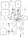
- Fig. 1 is a greatly simplified scheme of a drinks vending machine according to an embodiment of the invention reproduced.
- the drinks machine 10 of the Fig. 1 is adapted to prepare from a base liquid, in particular milk or water, by mixing with a concentrated, liquid additive, in particular chocolate or syrup or the like., In a vessel, in particular a cup 16, a finished beverage.
- the concentrated, liquid additive and the base liquid are introduced separately into the vessel or the cup 16 and mix there automatically.
- the beverage dispenser 10 may additionally be designed for the preparation and dispensing of coffee drinks, in which case a coffee preparation unit 29 (in Fig. 1 dashed lines) is provided, which the coffee beverage, with milk, milk foam or a flavoring syrup may or may be added, prepared and dispensed into the cup 16.
- a coffee preparation unit 29 in Fig. 1 dashed lines
- the coffee beverage, with milk, milk foam or a flavoring syrup may or may be added, prepared and dispensed into the cup 16.
- the concentrated, liquid additive is kept in a separate reservoir 11, which may be formed, for example, as an exchangeable canister. Other additives can be kept ready in further storage containers (see in particular Fig. 2 ).
- Fig. 1 is (optional) another reservoir 12 shown in dashed lines. From each of the reservoir 11, 12 a line 23 and 24 leads to an outlet 19 to be discharged from there into the cup 16. In the example of Fig. 1 the same outlet 19 is used for the two reservoirs and the additives therein; in the example of Fig. 2 On the other hand, each of the five different additives (reservoir 11a-e) has its own outlet (19a-e).
- a suitable pump P1, P2 is arranged, which is driven by a motor and is controlled by a central control unit 22 (in Fig. 1
- a central control unit 22 in Fig. 1
- Suitable pumps are because of the predominantly relatively high viscosity of the additives, especially peristaltic pumps, which can be used at the same time for the exact dosage of the additives.
- Controllable valves V1, V2 can also be used in the lines 23, 24, for example, to prevent overrun of the additives safely.
- the viscosity of the additive prior to delivery into the cup 16 via the outlet 19 is done by heating the additive either by means of an electric heater 32 or by means of hot steam in a arranged upstream of the outlet 19 Auffilvoriques 30.
- this heating device 30 of the one of the reservoir 11, 12 by means of the associated pump P1 or P2 funded additive by heated electrical heating or by thermal contact with or by direct mixing of hot steam, so that it comparatively thin liquid from the outlet 19 passes into the cup 16 below and there automatically mixed with the simultaneously filled base liquid.
- the reduction of the viscosity is effected on the one hand by the heating of the additive, and on the other hand by a certain degree of dilution with the water vapor condensing in the additive.
- the electric heater 32 is supplied, for example, from the central control unit 22 in a controlled manner with electrical energy.
- the steam introduced into the heating device 30 is preferably generated in a separate steam generator unit 13 and transported via an associated line 25 to the heating device 30.
- the steam generator unit 13 receives the water required for this purpose, for example from a water source 17, which may be formed as a water reservoir or as a water connection.
- the mixing and heating of the additive with the supplied via the line 25 (steam line) steam takes place when flowing through the heating device 30, so that the additive-steam mixture directly down to the subsequent outlet 19 exits.
- the outlet 19 can be "blown out" with a burst of steam via the line 25, whereby a dripping of the reduced viscosity in the additive is largely avoided.
- rinsing of the lines and channels acted upon by the additive can subsequently be provided in the heating device 30 and in the outlet 19 arranged behind by a rinsing liquid.
- a rinsing liquid is especially water, especially hot or hot water, in question, which is already present in a drinks vending machine, the hot drinks water-based such as coffee, soups, mulled wine or the like.
- a corresponding Wasseraufloomologist 14 (hot water heater, boiler) is then connected via a line 26 (hot water) to the heating device 30, so that introduced via a arranged in the line 26 valve V4 by means of a pump P3 hot water into the heating device 30 and the entire line section to to the bottom the outlet 19 can be flushed through inside.
- This process is also controlled by the control unit 22 via the pump P3 and the valve V4. It is expedient to feed the hot water used for rinsing between the valve V3 and the heating device 30 in the (steam) line 25.
- the water heating unit 14 may be replaced with a water tank.
- an additional "external rinse” is provided for the case that the outlet 19 is formed as a jacketed outlet, in which an inner tube 21 for the additive is concentrically surrounded by an outer shell 20.
- the annular space between the inner tube 21 and outer shell 20 can then be used to rid the free end of the inner tube 21 of externally adhering additive residues, encrustations, etc., with a rinsing fluid conveyed through the annular space.
- a further line 27 is branched off from the line 26 for the hot water and led via a controllable valve V5 to the heating device 30, where the hot water is fed into the annular space between inner tube 21 and outer casing 20 of the outlet 19.
- the flushing connection can also be arranged directly on the outlet 19.
- a chocolate drink is to be prepared, cold or hot milk is fed into the cup 16 through a separate milk dispenser unit 18 to the heated chocolate additive which is delivered from a milk source 15 to the milk dispenser unit 18 via a line 28 by a pump P4.
- the milk source 15 may comprise a reservoir for milk. But it can also produce the milk from a concentrate or milk powder by mixing with cold or hot water.
- Cold milk can be heated within the milk source 15, eg in a continuous flow heater or by adding hot steam. It is also conceivable, cold milk on the way to To heat milk dispensing unit 18 (in Fig.1 not shown).
- a controlled valve V6 in line 28 controls milk flow in addition to pump P4.
- FIG. 2 is the simplified scheme for the supply of five different additives in a beverage vending machine 10 'given again.
- Each of the additives is associated with its own storage tank 11a-e, its own heating device 30a-e and its own outlet 19a-e. This reliably prevents contamination of one additive by another.
- Each additive is conveyed via its own line with a pump P1a-e and a valve V1a-e to the corresponding heating device 30a-e, where it is mixed with steam from the steam generator unit 13 and heated.
- valves V3a-e are provided for the control of the steam supply.
- the line coming from the water heating unit 14 can optionally be switched via corresponding valves V4a-e to the hot steam lines leading from the steam generator unit 13 to the outlets 19a-e.
- An appropriate external rinse as in Fig. 1 is plotted for reasons of space only for the outlet 19a and via a valve V5a.
- the other outlets 19b-e can be flushed out in an analogous manner.
- it is also conceivable to provide for all outlets 19a-e by connecting all the annular spaces between inner tube and outer shell a common external flush, which is controlled only via a valve and, if necessary, all outlets 1 9a-e flushes together.
- the individual spouts 19a-e are in Fig. 2 for reasons of clarity in a row next to each other. However, in the actual drinks vending machines, they are spatially grouped together (eg, arranged in two parallel rows or in a ring shape) so that they can all dispense the heated additive into a cup underneath without having to move the cup. Of course, in this arrangement also the (in Fig. 2 not shown) milk dispensing unit 18 and other existing outlets in the machine (eg for coffee drinks) integrated.
- the present invention provides the following approach: Shortly before dispensing, the liquid chocolate is brought to a higher temperature with additional steam so as to lower the viscosity and facilitate mixing with the milk. The amount of steam must be adjusted so that the chocolate is not burned and the correct temperature is reached.
- the chocolate spout can be "blown out” with the steam and the dripping at the outlet is thereby reduced.
- water can also be introduced into the outlet via the steam path so as to allow an (internal) flushing.
- an external flushing of the spout can be provided.
Landscapes
- Engineering & Computer Science (AREA)
- Food Science & Technology (AREA)
- Apparatus For Making Beverages (AREA)
- Beverage Vending Machines With Cups, And Gas Or Electricity Vending Machines (AREA)
- Devices For Dispensing Beverages (AREA)
Claims (21)
- Procédé de préparation d'une boisson mélangée à partir d'un liquide de base et d'un additif liquide concentré conférant une saveur spécifique à la boisson mélangée, procédé dans lequel l'additif liquide concentré est extrait d'un réservoir de stockage (11, 12 ; 11a-e), est ensuite chauffé par l'apport d'énergie, et l'additif liquide concentré chauffé est ensuite mélangé au liquide de base, caractérisé en ce que l'additif liquide concentré chauffé et le liquide de base sont distribués par des orifices d'écoulement séparés (18, 19 ; 19a-e) dans un récipient posé dessous, en particulier un gobelet (16), et s'y mélangent automatiquement.
- Procédé selon la revendication 1, caractérisé en ce que l'additif liquide concentré est extrait du réservoir de stockage (11, 12 ; 11a-e) en quantité prédéterminée et est amené par une conduite associée (23, 24) au moyen d'une pompe (P1, P2 ; P1a-e) disposée dans la conduite à un dispositif de chauffage (30 ; 30a-e), et en ce qu'une telle quantité d'énergie est apportée au dispositif de chauffage (30 ; 30a-e) que l'additif liquide concentré est chauffé à une température prédéterminée.
- Procédé selon la revendication 2, caractérisé en ce que le dispositif de chauffage (30 ; 30a-e) présente un chauffage électrique (32), et en ce que l'énergie est apportée sous forme d'énergie électrique.
- Procédé selon la revendication 2, caractérisé en ce que l'énergie est apportée au dispositif de chauffage (30 ; 30a-e) sous forme de vapeur chaude, en ce que la vapeur est générée dans une unité de génération de vapeur (13) et est amenée au dispositif de chauffage (30 ; 30a-e) par une conduite associée (25), en ce que la vapeur amenée est mélangée à l'additif liquide concentré dans le dispositif de chauffage (30 ; 30a-e), et en ce que le brassage de vapeur et d'additif liquide concentré et le chauffage associé de l'additif liquide concentré ont lieu pendant le passage de l'additif liquide concentré à travers le dispositif de chauffage (30 ; 30a-e).
- Procédé selon la revendication 2, caractérisé en ce que la température de l'additif liquide concentré chauffé est mesurée et surveillée au moyen d'un capteur de température (31) disposé dans le dispositif de chauffage (30 ; 30a-e).
- Procédé selon la revendication 1, caractérisé en ce que l'additif liquide concentré chauffé et le liquide de base sont distribués en même temps dans le récipient (16) posé dessous.
- Procédé selon la revendication 1, caractérisé en ce que l'additif liquide concentré chauffé comprend du chocolat et en ce que le liquide de base est du lait.
- Procédé selon la revendication 1, caractérisé en ce que l'additif liquide concentré chauffé comprend un sirop et en ce que le liquide de base est de l'eau.
- Procédé selon la revendication 2, caractérisé en ce que l'énergie est apportée au dispositif de chauffage (30 ; 30a-e) sous forme de vapeur chaude, en ce que la vapeur est générée dans une unité de génération de vapeur (13) et est amenée au dispositif de chauffage (30 ; 30a-e) par une conduite associée (25), et en ce que l'orifice d'écoulement (19 ; 19a-e) pour l'additif liquide concentré, après distribution de l'additif liquide concentré chauffé dans le récipient (16) posé dessous, est purgé avec un supplément de vapeur issu de l'unité de génération de vapeur (13).
- Procédé selon la revendication 1, caractérisé en ce que l'orifice d'écoulement (19 ; 19a-e) pour l'additif liquide concentré, après distribution de l'additif liquide concentré chauffé dans le récipient (16) posé dessous, est rincé avec un liquide de rinçage, et en ce que comme liquide de rinçage, de l'eau chaude est utilisée qui est amenée d'une unité de chauffage d'eau (14) à l'orifice d'écoulement (19 ; 19a-e) par une conduite associée.
- Procédé selon la revendication 2, caractérisé en ce que l'énergie est apportée au dispositif de chauffage (30 ; 30a-e) sous la forme de vapeur chaude, en ce que la vapeur est générée dans une unité de génération de vapeur (13) et est amenée au dispositif de chauffage (30 ; 30a-e) par une conduite associée (25), en ce que la vapeur amenée est mélangée à l'additif liquide concentré dans le dispositif de chauffage (30 ; 30a-e), et en ce que l'orifice d'écoulement (19 ; 19a-e) pour l'additif liquide concentré, après distribution de l'additif liquide concentré chauffé dans le récipient (16) posé dessous, est rincé avec de l'eau, et en ce que l'eau utilisée pour le rinçage est introduite dans une conduite (25) allant de l'unité de génération de vapeur (13) au dispositif de chauffage (30 ; 30a-e).
- Procédé selon la revendication 1, caractérisé en ce que l'orifice d'écoulement (19 ; 19a-e) pour l'additif liquide concentré, après distribution de l'additif liquide concentré chauffé dans le récipient (16) posé dessous, est rincé avec un liquide de rinçage, en ce que l'orifice d'écoulement (19 ; 19a-e) pour l'additif liquide concentré comprend une enveloppe extérieure (20) et un tuyau intérieur (21) disposé de manière concentrique à l'intérieur de celle-ci pour le transport de l'additif liquide concentré, et en ce que du liquide de rinçage est libéré vers l'extérieur entre l'enveloppe extérieure (20) et le tuyau intérieur (21) pour le rinçage de la face extérieure du tuyau intérieur (21).
- Distributeur de boissons (10) pour exécuter le procédé selon la revendication 1, comprenant au moins un réservoir de stockage (11, 12 ; 11a-e) pour l'additif liquide concentré pour la préparation de la boisson mélangée, des moyens (15, 28, P4, V6) pour amener une quantité prédéterminée d'un liquide de base pour la boisson mélangée à préparer, et au moins un dispositif de chauffage (30 ; 30a-e) présentant une première entrée communiquant avec ledit au moins un réservoir de stockage (11, 12 ; 11a-e) par une première conduite (23, 24), dans lequel ledit au moins un dispositif de chauffage (30 ; 30a-e) est réalisé pour chauffer l'additif liquide concentré amené par la première conduite (23, 24) par de l'énergie apportée, caractérisé en ce qu'un premier dispositif (18) est prévu par lequel le liquide de base peut être distribué dans un récipient posé dessous, en particulier un gobelet (16), et en ce qu'un deuxième dispositif (19, 20, 21 ; 19a-e), séparé du premier dispositif, est prévu, par lequel l'additif liquide concentré chauffé peut être distribué dans le récipient (16) posé dessous.
- Distributeur de boissons selon la revendication 13, caractérisé en ce que le deuxième dispositif comprend au moins un orifice d'écoulement (19 ; 19a-e) en communication directe avec ledit au moins un dispositif de chauffage (30 ; 30a-e).
- Distributeur de boissons selon la revendication 13, caractérisé en ce que dans la première conduite (23, 24) sont disposés des moyens pour débiter l'additif liquide concentré, en particulier sous la forme d'une pompe (P1, P2 ; P1a-e).
- Distributeur de boissons selon la revendication 13, caractérisé en ce que dans le dispositif de chauffage (30 ; 30a-e) un chauffage électrique (32) est disposé pour chauffer l'additif liquide concentré amené par la première conduite (23, 24).
- Distributeur de boissons selon la revendication 13, caractérisé en ce qu'une unité de génération de vapeur (13) pour générer de la vapeur pour chauffer l'additif liquide concentré est prévue, en ce que le dispositif de chauffage (30 ; 30a-e) présente une deuxième entrée reliée à l'unité de génération de vapeur (13) par une deuxième conduite (25), en ce que dans la deuxième conduite (25) est disposée une première vanne réglable (V3 ; V3a-e) pour régler la quantité de la vapeur amenée au dispositif de chauffage (30 ; 30a-e), et en ce qu'une unité de chauffage d'eau (14) est prévue, dont la sortie communique avec le deuxième dispositif (19, 20, 21 ; 19a-e) par une troisième conduite (26).
- Distributeur de boissons selon la revendication 17, caractérisé en ce que la troisième conduite (26) débouche dans la deuxième conduite (25) entre la première vanne réglable (V3 ; V3a-e) et le dispositif de chauffage (30 ; 30a-e).
- Distributeur de boissons selon la revendication 17, caractérisé en ce que dans la troisième conduite (26) est disposée une pompe (P3) pour débiter l'eau de l'unité de chauffage d'eau (14), en ce que le deuxième dispositif comprend au moins un orifice d'écoulement (19 ; 19a-e) communiquant directement avec une sortie dudit au moins un dispositif de chauffage (30 ; 30a-e), en ce que ledit au moins un orifice d'écoulement (19 ; 19a-e) comprend une enveloppe extérieure (20) et un tuyau intérieur (21) disposé de manière concentrique à l'intérieur de celle-ci pour le transport de l'additif liquide concentré, en ce que pour le rinçage de la face extérieure du tuyau intérieur (21), une quatrième conduite (27) relie la sortie de l'unité de chauffage d'eau (14) à l'espace entre l'enveloppe extérieure (20) et le tuyau intérieur (21), et en ce que la quatrième conduite (27) se sépare de la troisième conduite (26) en aval de la pompe (P3).
- Distributeur de boissons selon la revendication 13, caractérisé en ce que plusieurs réservoirs de stockage (11, 12 ; 11a-e) sont prévus pour différents additifs liquides concentrés, en ce qu'à chacun des réservoirs de stockage (11, 12 ; 11a-e) est attribué son propre dispositif de chauffage (30 ; 30a-e) ainsi qu'un deuxième dispositif propre (19, 20, 21 ; 19a-e), et en ce que chaque dispositif de chauffage (30 ; 30a-e) communique avec le réservoir de stockage (11, 12 ; 11a-e) associé par une première conduite associée (23, 24).
- Distributeur de boissons selon la revendication 13, caractérisé en ce qu'une unité de commande (22) est prévue pour la commande automatique des opérations de débit, de chauffage et de distribution.
Applications Claiming Priority (2)
| Application Number | Priority Date | Filing Date | Title |
|---|---|---|---|
| CH00860/13A CH707966A1 (de) | 2013-04-25 | 2013-04-25 | Verfahren zum Zubereiten eines Mischgetränkes sowie Getränkeautomat zur Durchführung des Verfahrens. |
| PCT/EP2014/053183 WO2014173555A1 (fr) | 2013-04-25 | 2014-02-19 | Procédé de préparation d'une boisson mélangée et distributeur automatique de boissons permettant la mise en œuvre de ce procédé |
Publications (2)
| Publication Number | Publication Date |
|---|---|
| EP2988635A1 EP2988635A1 (fr) | 2016-03-02 |
| EP2988635B1 true EP2988635B1 (fr) | 2019-04-03 |
Family
ID=48534099
Family Applications (1)
| Application Number | Title | Priority Date | Filing Date |
|---|---|---|---|
| EP14705502.4A Active EP2988635B1 (fr) | 2013-04-25 | 2014-02-19 | Procédé de préparation d'une boisson mélangée et distributeur automatique de boissons permettant la mise en oeuvre de ce procédé |
Country Status (3)
| Country | Link |
|---|---|
| EP (1) | EP2988635B1 (fr) |
| CH (1) | CH707966A1 (fr) |
| WO (1) | WO2014173555A1 (fr) |
Families Citing this family (3)
| Publication number | Priority date | Publication date | Assignee | Title |
|---|---|---|---|---|
| EP3337365A1 (fr) * | 2015-08-17 | 2018-06-27 | Nestec S.A. | Système anti-goutte |
| DE102016213141A1 (de) * | 2016-07-19 | 2018-01-25 | Bayerische Motoren Werke Aktiengesellschaft | Befüllsystem |
| US12096875B2 (en) * | 2020-02-04 | 2024-09-24 | The Quaker Oats Company | System and apparatus for providing cooked food |
Family Cites Families (5)
| Publication number | Priority date | Publication date | Assignee | Title |
|---|---|---|---|---|
| US2954145A (en) * | 1955-03-08 | 1960-09-27 | Raymond E Mccauley | Beverage making machine |
| WO2008059432A1 (fr) * | 2006-11-14 | 2008-05-22 | Koninklijke Philips Electronics N.V. | Dispositif de calibrage pour un appareil qui prépare une boisson à partir d'eau et d'un produit instantané |
| EP2050368B1 (fr) | 2007-10-16 | 2010-04-14 | Gruppo Cimbali S.p.A. | Machine à café avec distributeur pour boissons à base de chocolat prêtes à consommer |
| EP2060211B1 (fr) | 2007-11-19 | 2010-09-08 | Gruppo Cimbali S.p.A. | Appareil pour la préparation et la distribution d'une boisson, en particulier une boisson chocolatée dans une machine à café |
| US9402502B2 (en) | 2010-07-02 | 2016-08-02 | Luigi Lavazza S.P.A. | Hot-beverage-making apparatus, in particular for milk beverages such as cappuccino, chocolate and the like |
-
2013
- 2013-04-25 CH CH00860/13A patent/CH707966A1/de not_active Application Discontinuation
-
2014
- 2014-02-19 WO PCT/EP2014/053183 patent/WO2014173555A1/fr not_active Ceased
- 2014-02-19 EP EP14705502.4A patent/EP2988635B1/fr active Active
Non-Patent Citations (1)
| Title |
|---|
| None * |
Also Published As
| Publication number | Publication date |
|---|---|
| WO2014173555A1 (fr) | 2014-10-30 |
| EP2988635A1 (fr) | 2016-03-02 |
| CH707966A1 (de) | 2014-10-31 |
Similar Documents
| Publication | Publication Date | Title |
|---|---|---|
| EP2854608B1 (fr) | Unité de distribution pour un distributeur automatique de boissons, distributeur automatique de boissons équipé d'une telle unité de distribution ainsi que procédé de fonctionnement d'un tel distributeur automatique de boissons | |
| EP2030538B1 (fr) | Dispositif et procédé de préparation de boissons chaudes aromatisées, en particulier du café et du thé | |
| EP2011421B1 (fr) | Dispositif destiné à la production de boissons à base de lait | |
| EP2279149B1 (fr) | Procédé et système de remplissage destinés au remplissage de bouteilles ou de récipients analogues par un produit liquide | |
| EP2157895B1 (fr) | Appareil de préparation de boissons | |
| EP2798989B1 (fr) | Dispositif de préparation de boisson, des moyens de chauffage du lait ainsi que le procédé d'opération | |
| EP2294952B1 (fr) | Dispositif de distribution de lait et/ou de mousse de lait | |
| EP2494895B1 (fr) | Procédé de sortie de boissons d'un automate à boissons | |
| EP2190327B1 (fr) | Dispositif de production et de distribution de boissons composées de mélanges de lait et de substances aromatisantes liquides | |
| EP2157892A1 (fr) | Unité de percolation pour un appareil de préparation de boissons | |
| EP3870005B1 (fr) | Procédé de production d'une boisson à base de café dans un distributeur de café | |
| WO2010017888A1 (fr) | Procédé pour conditionner un produit constitué d'au moins un premier et un deuxième composant | |
| EP3099208B1 (fr) | Module d'arôme et procédé pour faire fonctionner un tel module d'arôme | |
| WO2007014654A1 (fr) | Machine a cafe | |
| EP2988635B1 (fr) | Procédé de préparation d'une boisson mélangée et distributeur automatique de boissons permettant la mise en oeuvre de ce procédé | |
| DE202014102435U1 (de) | Selbstbedienungs-Getränkeautomat | |
| EP4676285A1 (fr) | Machine de distribution de boisson comprenant un dispositif de nettoyage | |
| EP4044880A1 (fr) | Procédé et appareil de production de boissons, de préférence de boissons lactées ou de lait mousseux | |
| AT504103B1 (de) | Kaffeemaschine | |
| DE202011051696U1 (de) | Einrichtung zum Ausgeben eines mittels Dampf erwärmten fließfähigen Nahrungsmittels |
Legal Events
| Date | Code | Title | Description |
|---|---|---|---|
| PUAI | Public reference made under article 153(3) epc to a published international application that has entered the european phase |
Free format text: ORIGINAL CODE: 0009012 |
|
| 17P | Request for examination filed |
Effective date: 20150930 |
|
| AK | Designated contracting states |
Kind code of ref document: A1 Designated state(s): AL AT BE BG CH CY CZ DE DK EE ES FI FR GB GR HR HU IE IS IT LI LT LU LV MC MK MT NL NO PL PT RO RS SE SI SK SM TR |
|
| AX | Request for extension of the european patent |
Extension state: BA ME |
|
| DAX | Request for extension of the european patent (deleted) | ||
| GRAP | Despatch of communication of intention to grant a patent |
Free format text: ORIGINAL CODE: EPIDOSNIGR1 |
|
| STAA | Information on the status of an ep patent application or granted ep patent |
Free format text: STATUS: GRANT OF PATENT IS INTENDED |
|
| INTG | Intention to grant announced |
Effective date: 20180828 |
|
| GRAS | Grant fee paid |
Free format text: ORIGINAL CODE: EPIDOSNIGR3 |
|
| GRAA | (expected) grant |
Free format text: ORIGINAL CODE: 0009210 |
|
| STAA | Information on the status of an ep patent application or granted ep patent |
Free format text: STATUS: THE PATENT HAS BEEN GRANTED |
|
| AK | Designated contracting states |
Kind code of ref document: B1 Designated state(s): AL AT BE BG CH CY CZ DE DK EE ES FI FR GB GR HR HU IE IS IT LI LT LU LV MC MK MT NL NO PL PT RO RS SE SI SK SM TR |
|
| REG | Reference to a national code |
Ref country code: GB Ref legal event code: FG4D Free format text: NOT ENGLISH |
|
| REG | Reference to a national code |
Ref country code: CH Ref legal event code: EP Ref country code: AT Ref legal event code: REF Ref document number: 1114693 Country of ref document: AT Kind code of ref document: T Effective date: 20190415 |
|
| REG | Reference to a national code |
Ref country code: DE Ref legal event code: R096 Ref document number: 502014011308 Country of ref document: DE |
|
| REG | Reference to a national code |
Ref country code: IE Ref legal event code: FG4D Free format text: LANGUAGE OF EP DOCUMENT: GERMAN |
|
| REG | Reference to a national code |
Ref country code: CH Ref legal event code: NV Representative=s name: IPRIME RENTSCH KAELIN AG, CH |
|
| REG | Reference to a national code |
Ref country code: NL Ref legal event code: FP |
|
| REG | Reference to a national code |
Ref country code: LT Ref legal event code: MG4D |
|
| PG25 | Lapsed in a contracting state [announced via postgrant information from national office to epo] |
Ref country code: AL Free format text: LAPSE BECAUSE OF FAILURE TO SUBMIT A TRANSLATION OF THE DESCRIPTION OR TO PAY THE FEE WITHIN THE PRESCRIBED TIME-LIMIT Effective date: 20190403 Ref country code: CZ Free format text: LAPSE BECAUSE OF FAILURE TO SUBMIT A TRANSLATION OF THE DESCRIPTION OR TO PAY THE FEE WITHIN THE PRESCRIBED TIME-LIMIT Effective date: 20190403 Ref country code: ES Free format text: LAPSE BECAUSE OF FAILURE TO SUBMIT A TRANSLATION OF THE DESCRIPTION OR TO PAY THE FEE WITHIN THE PRESCRIBED TIME-LIMIT Effective date: 20190403 Ref country code: SE Free format text: LAPSE BECAUSE OF FAILURE TO SUBMIT A TRANSLATION OF THE DESCRIPTION OR TO PAY THE FEE WITHIN THE PRESCRIBED TIME-LIMIT Effective date: 20190403 Ref country code: NO Free format text: LAPSE BECAUSE OF FAILURE TO SUBMIT A TRANSLATION OF THE DESCRIPTION OR TO PAY THE FEE WITHIN THE PRESCRIBED TIME-LIMIT Effective date: 20190703 Ref country code: PT Free format text: LAPSE BECAUSE OF FAILURE TO SUBMIT A TRANSLATION OF THE DESCRIPTION OR TO PAY THE FEE WITHIN THE PRESCRIBED TIME-LIMIT Effective date: 20190803 Ref country code: HR Free format text: LAPSE BECAUSE OF FAILURE TO SUBMIT A TRANSLATION OF THE DESCRIPTION OR TO PAY THE FEE WITHIN THE PRESCRIBED TIME-LIMIT Effective date: 20190403 Ref country code: FI Free format text: LAPSE BECAUSE OF FAILURE TO SUBMIT A TRANSLATION OF THE DESCRIPTION OR TO PAY THE FEE WITHIN THE PRESCRIBED TIME-LIMIT Effective date: 20190403 Ref country code: LT Free format text: LAPSE BECAUSE OF FAILURE TO SUBMIT A TRANSLATION OF THE DESCRIPTION OR TO PAY THE FEE WITHIN THE PRESCRIBED TIME-LIMIT Effective date: 20190403 |
|
| PG25 | Lapsed in a contracting state [announced via postgrant information from national office to epo] |
Ref country code: LV Free format text: LAPSE BECAUSE OF FAILURE TO SUBMIT A TRANSLATION OF THE DESCRIPTION OR TO PAY THE FEE WITHIN THE PRESCRIBED TIME-LIMIT Effective date: 20190403 Ref country code: BG Free format text: LAPSE BECAUSE OF FAILURE TO SUBMIT A TRANSLATION OF THE DESCRIPTION OR TO PAY THE FEE WITHIN THE PRESCRIBED TIME-LIMIT Effective date: 20190703 Ref country code: RS Free format text: LAPSE BECAUSE OF FAILURE TO SUBMIT A TRANSLATION OF THE DESCRIPTION OR TO PAY THE FEE WITHIN THE PRESCRIBED TIME-LIMIT Effective date: 20190403 Ref country code: GR Free format text: LAPSE BECAUSE OF FAILURE TO SUBMIT A TRANSLATION OF THE DESCRIPTION OR TO PAY THE FEE WITHIN THE PRESCRIBED TIME-LIMIT Effective date: 20190704 Ref country code: PL Free format text: LAPSE BECAUSE OF FAILURE TO SUBMIT A TRANSLATION OF THE DESCRIPTION OR TO PAY THE FEE WITHIN THE PRESCRIBED TIME-LIMIT Effective date: 20190403 |
|
| PG25 | Lapsed in a contracting state [announced via postgrant information from national office to epo] |
Ref country code: IS Free format text: LAPSE BECAUSE OF FAILURE TO SUBMIT A TRANSLATION OF THE DESCRIPTION OR TO PAY THE FEE WITHIN THE PRESCRIBED TIME-LIMIT Effective date: 20190803 |
|
| REG | Reference to a national code |
Ref country code: DE Ref legal event code: R097 Ref document number: 502014011308 Country of ref document: DE |
|
| PG25 | Lapsed in a contracting state [announced via postgrant information from national office to epo] |
Ref country code: RO Free format text: LAPSE BECAUSE OF FAILURE TO SUBMIT A TRANSLATION OF THE DESCRIPTION OR TO PAY THE FEE WITHIN THE PRESCRIBED TIME-LIMIT Effective date: 20190403 Ref country code: DK Free format text: LAPSE BECAUSE OF FAILURE TO SUBMIT A TRANSLATION OF THE DESCRIPTION OR TO PAY THE FEE WITHIN THE PRESCRIBED TIME-LIMIT Effective date: 20190403 Ref country code: SK Free format text: LAPSE BECAUSE OF FAILURE TO SUBMIT A TRANSLATION OF THE DESCRIPTION OR TO PAY THE FEE WITHIN THE PRESCRIBED TIME-LIMIT Effective date: 20190403 Ref country code: EE Free format text: LAPSE BECAUSE OF FAILURE TO SUBMIT A TRANSLATION OF THE DESCRIPTION OR TO PAY THE FEE WITHIN THE PRESCRIBED TIME-LIMIT Effective date: 20190403 |
|
| PLBE | No opposition filed within time limit |
Free format text: ORIGINAL CODE: 0009261 |
|
| STAA | Information on the status of an ep patent application or granted ep patent |
Free format text: STATUS: NO OPPOSITION FILED WITHIN TIME LIMIT |
|
| PG25 | Lapsed in a contracting state [announced via postgrant information from national office to epo] |
Ref country code: SM Free format text: LAPSE BECAUSE OF FAILURE TO SUBMIT A TRANSLATION OF THE DESCRIPTION OR TO PAY THE FEE WITHIN THE PRESCRIBED TIME-LIMIT Effective date: 20190403 |
|
| 26N | No opposition filed |
Effective date: 20200106 |
|
| PG25 | Lapsed in a contracting state [announced via postgrant information from national office to epo] |
Ref country code: TR Free format text: LAPSE BECAUSE OF FAILURE TO SUBMIT A TRANSLATION OF THE DESCRIPTION OR TO PAY THE FEE WITHIN THE PRESCRIBED TIME-LIMIT Effective date: 20190403 |
|
| PG25 | Lapsed in a contracting state [announced via postgrant information from national office to epo] |
Ref country code: SI Free format text: LAPSE BECAUSE OF FAILURE TO SUBMIT A TRANSLATION OF THE DESCRIPTION OR TO PAY THE FEE WITHIN THE PRESCRIBED TIME-LIMIT Effective date: 20190403 |
|
| GBPC | Gb: european patent ceased through non-payment of renewal fee |
Effective date: 20200219 |
|
| REG | Reference to a national code |
Ref country code: BE Ref legal event code: MM Effective date: 20200229 |
|
| PG25 | Lapsed in a contracting state [announced via postgrant information from national office to epo] |
Ref country code: MC Free format text: LAPSE BECAUSE OF FAILURE TO SUBMIT A TRANSLATION OF THE DESCRIPTION OR TO PAY THE FEE WITHIN THE PRESCRIBED TIME-LIMIT Effective date: 20190403 Ref country code: LU Free format text: LAPSE BECAUSE OF NON-PAYMENT OF DUE FEES Effective date: 20200219 |
|
| PG25 | Lapsed in a contracting state [announced via postgrant information from national office to epo] |
Ref country code: FR Free format text: LAPSE BECAUSE OF NON-PAYMENT OF DUE FEES Effective date: 20200229 Ref country code: GB Free format text: LAPSE BECAUSE OF NON-PAYMENT OF DUE FEES Effective date: 20200219 Ref country code: IE Free format text: LAPSE BECAUSE OF NON-PAYMENT OF DUE FEES Effective date: 20200219 |
|
| PG25 | Lapsed in a contracting state [announced via postgrant information from national office to epo] |
Ref country code: BE Free format text: LAPSE BECAUSE OF NON-PAYMENT OF DUE FEES Effective date: 20200229 |
|
| PG25 | Lapsed in a contracting state [announced via postgrant information from national office to epo] |
Ref country code: MT Free format text: LAPSE BECAUSE OF FAILURE TO SUBMIT A TRANSLATION OF THE DESCRIPTION OR TO PAY THE FEE WITHIN THE PRESCRIBED TIME-LIMIT Effective date: 20190403 Ref country code: CY Free format text: LAPSE BECAUSE OF FAILURE TO SUBMIT A TRANSLATION OF THE DESCRIPTION OR TO PAY THE FEE WITHIN THE PRESCRIBED TIME-LIMIT Effective date: 20190403 |
|
| PG25 | Lapsed in a contracting state [announced via postgrant information from national office to epo] |
Ref country code: MK Free format text: LAPSE BECAUSE OF FAILURE TO SUBMIT A TRANSLATION OF THE DESCRIPTION OR TO PAY THE FEE WITHIN THE PRESCRIBED TIME-LIMIT Effective date: 20190403 |
|
| P01 | Opt-out of the competence of the unified patent court (upc) registered |
Effective date: 20230525 |
|
| PGFP | Annual fee paid to national office [announced via postgrant information from national office to epo] |
Ref country code: AT Payment date: 20250123 Year of fee payment: 12 Ref country code: CH Payment date: 20250301 Year of fee payment: 12 |
|
| PGFP | Annual fee paid to national office [announced via postgrant information from national office to epo] |
Ref country code: NL Payment date: 20260127 Year of fee payment: 13 |
|
| REG | Reference to a national code |
Ref country code: CH Ref legal event code: U11 Free format text: ST27 STATUS EVENT CODE: U-0-0-U10-U11 (AS PROVIDED BY THE NATIONAL OFFICE) Effective date: 20260301 |
|
| PGFP | Annual fee paid to national office [announced via postgrant information from national office to epo] |
Ref country code: DE Payment date: 20260206 Year of fee payment: 13 |
|
| PGFP | Annual fee paid to national office [announced via postgrant information from national office to epo] |
Ref country code: IT Payment date: 20260210 Year of fee payment: 13 |