EP2988846B2 - Milieu filtrant, en particulier milieu de filtre à air et élément de filtre, en particulier élément de filtre à air, pourvu d'un milieu filtrant - Google Patents
Milieu filtrant, en particulier milieu de filtre à air et élément de filtre, en particulier élément de filtre à air, pourvu d'un milieu filtrant Download PDFInfo
- Publication number
- EP2988846B2 EP2988846B2 EP14718378.4A EP14718378A EP2988846B2 EP 2988846 B2 EP2988846 B2 EP 2988846B2 EP 14718378 A EP14718378 A EP 14718378A EP 2988846 B2 EP2988846 B2 EP 2988846B2
- Authority
- EP
- European Patent Office
- Prior art keywords
- filter layer
- section
- filter
- fibers
- packing density
- Prior art date
- Legal status (The legal status is an assumption and is not a legal conclusion. Google has not performed a legal analysis and makes no representation as to the accuracy of the status listed.)
- Active
Links
Images


Classifications
-
- B—PERFORMING OPERATIONS; TRANSPORTING
- B01—PHYSICAL OR CHEMICAL PROCESSES OR APPARATUS IN GENERAL
- B01D—SEPARATION
- B01D39/00—Filtering material for liquid or gaseous fluids
- B01D39/14—Other self-supporting filtering material ; Other filtering material
- B01D39/16—Other self-supporting filtering material ; Other filtering material of organic material, e.g. synthetic fibres
- B01D39/1607—Other self-supporting filtering material ; Other filtering material of organic material, e.g. synthetic fibres the material being fibrous
- B01D39/1623—Other self-supporting filtering material ; Other filtering material of organic material, e.g. synthetic fibres the material being fibrous of synthetic origin
-
- B—PERFORMING OPERATIONS; TRANSPORTING
- B01—PHYSICAL OR CHEMICAL PROCESSES OR APPARATUS IN GENERAL
- B01D—SEPARATION
- B01D39/00—Filtering material for liquid or gaseous fluids
- B01D39/14—Other self-supporting filtering material ; Other filtering material
- B01D39/16—Other self-supporting filtering material ; Other filtering material of organic material, e.g. synthetic fibres
- B01D39/18—Other self-supporting filtering material ; Other filtering material of organic material, e.g. synthetic fibres the material being cellulose or derivatives thereof
-
- B—PERFORMING OPERATIONS; TRANSPORTING
- B01—PHYSICAL OR CHEMICAL PROCESSES OR APPARATUS IN GENERAL
- B01D—SEPARATION
- B01D46/00—Filters or filtering processes specially modified for separating dispersed particles from gases or vapours
- B01D46/52—Particle separators, e.g. dust precipitators, using filters embodying folded corrugated or wound sheet material
- B01D46/521—Particle separators, e.g. dust precipitators, using filters embodying folded corrugated or wound sheet material using folded, pleated material
-
- B—PERFORMING OPERATIONS; TRANSPORTING
- B01—PHYSICAL OR CHEMICAL PROCESSES OR APPARATUS IN GENERAL
- B01D—SEPARATION
- B01D2239/00—Aspects relating to filtering material for liquid or gaseous fluids
- B01D2239/02—Types of fibres, filaments or particles, self-supporting or supported materials
- B01D2239/025—Types of fibres, filaments or particles, self-supporting or supported materials comprising nanofibres
-
- B—PERFORMING OPERATIONS; TRANSPORTING
- B01—PHYSICAL OR CHEMICAL PROCESSES OR APPARATUS IN GENERAL
- B01D—SEPARATION
- B01D2239/00—Aspects relating to filtering material for liquid or gaseous fluids
- B01D2239/06—Filter cloth, e.g. knitted, woven non-woven; self-supported material
- B01D2239/065—More than one layer present in the filtering material
-
- B—PERFORMING OPERATIONS; TRANSPORTING
- B01—PHYSICAL OR CHEMICAL PROCESSES OR APPARATUS IN GENERAL
- B01D—SEPARATION
- B01D2239/00—Aspects relating to filtering material for liquid or gaseous fluids
- B01D2239/12—Special parameters characterising the filtering material
- B01D2239/1208—Porosity
-
- B—PERFORMING OPERATIONS; TRANSPORTING
- B01—PHYSICAL OR CHEMICAL PROCESSES OR APPARATUS IN GENERAL
- B01D—SEPARATION
- B01D2239/00—Aspects relating to filtering material for liquid or gaseous fluids
- B01D2239/12—Special parameters characterising the filtering material
- B01D2239/1233—Fibre diameter
Definitions
- the invention relates to the technical field of treatment and filtering of fluids and in particular air, for example the filtering of liquid such as oil or of air for internal combustion engines.
- Air filters are used, for example, in the air supply of internal combustion engines, in order to clean the air supplied for combustion of pollutants and dirt particles, so that only cleaned air is supplied to a combustion process in the internal combustion engine.
- An air filter has an inflow opening for uncleaned raw air and an outflow opening for the filtered clean air and an air filter medium, with the air filter medium fulfilling the actual filter function.
- the internal combustion engine is supplied with air via the outflow opening of the air filter, with the internal combustion engine sucking in the required air or air quantity.
- the air filter medium consists, for example, of a filter paper through which the air to be filtered flows when the internal combustion engine draws in air, so that the dirt particles in the air filter medium are separated or separated from the air flowing through.
- the air filter media can be pleated (pleated filter) or have a multitude of filter chambers (flute filter) to increase the surface area of the filter, which also extends the life of an air filter element, since a larger filter surface area can hold more dirt particles before the dust caused by separated Pressure loss on the air filter medium has increased in such a way that the performance of the internal combustion engine decreases.
- EP 2 060 311 A1 describes an air filter medium for a vacuum cleaner bag with at least one layer of a dry-laid nonwoven fabric which has a polymeric continuous filament
- U.S. 2011/259813 A1 discloses a filter medium having a first filter layer and a second nanofiber layer.
- the first filter layer has at least two fiber phases, an "open” fiber phase and a “dense” fiber phase.
- the relative downstream position of the two fiber phases can be reversed.
- the respective fibers may form an "interfiber phase” (middle section) between two adjacent fiber phases.
- an air filter element according to claim 1 is provided with a filter medium having a first filter layer and a second filter layer.
- the first filter layer has a first filter layer section and a second filter layer section, the second filter layer section being arranged downstream of the first filter layer section in a flow direction of the filter medium.
- the first filter layer section has a first packing density of fibers or a first packing density value and the second filter layer section has a second packing density of fibers deviating from the first packing density of fibers or a second packing density value deviating from the first packing density value.
- the second filter layer is arranged behind the first filter layer in the flow direction and has nanofibers and can be a nanofiber filter layer in one embodiment.
- the packing density and a packing density value are in particular the mean packing density or the mean packing density value of a filter layer section or a filter layer.
- the direction of flow runs transversely or orthogonally to the first and second filter layers and thus also transversely or orthogonally to the first and second filter layer sections of the first filter layer.
- the air flow to be filtered thus flows through all filter layers of the air filter medium and also all filter layer sections of each filter layer.
- the filter layer sections arranged one behind the other with different packing densities mean that the filter medium stores dirt particles in its volume and, depending on the size of the dirt particles, separates them one after the other, namely the comparatively large dirt particles first, i. H. through the first filter layer section with a high porosity value, and the finer dirt particles through the second filter layer section with a lower porosity value, which is lower in the direction of flow.
- the second filter layer additionally provides a final filter function through a nanofiber filter layer. This allows the smallest dirt particles to be filtered out of the fluid flow to be filtered.
- the second filter layer has pores with a smaller size, in particular compared to the first filter layer and above all to the second filter layer section, so that finer dirt particles can be filtered out of the fluid to be filtered.
- a filter layer section is a plane of a filter layer of the filter medium, wherein the filter layer section extends through at least part of the filter layer and the filter medium transversely to the flow direction. If a fluid flow is guided through the filter medium, the fluid flow traverses one or more filter layer sections in the direction of flow one behind the other.
- a filter layer section is thus a depth section of a filter layer in the direction of flow with a definable depth and can, for example, be of the order of a few ⁇ m, e.g. B. between 10 microns and 100 microns, or of a few mm, z. B. 1 mm.
- a fluid flow can be a gas or liquid flow that is guided through the filter element for the purpose of filtering or separating dirt or dirt particles. It should be noted that in the following an air filter is partially described, but the explanations regarding the structure of the air filter can also refer to a filter medium in general.
- the packing density is a measure of the proportion of filter fibers per depth of a filter layer section, i. H. that the packing density is to be understood as the packing density of fibers or filter fibers per unit area or volume.
- the packing density can be determined for each filter layer and for each filter layer section, for example via micrographs or sectional images of the air filter medium embedded in synthetic resin. Such a micrograph is recorded and the area of the micrograph is evaluated in such a way that the proportion of the area of the micrograph covered by fibers and the total area of a filter layer section or the proportion of the area of the micrograph not covered by fibers and the total area of a filter layer section are in relation to one another be set.
- the packing density can be determined on the image recording by evaluating the pixels on which a fiber can be seen and those pixels that indicate a gap. If the total number of pixels in the filter layer section is fixed or known, the packing density can be determined by relating the number of pixels showing a filter fiber to the total number of pixels in the filter layer section. Alternatively, the number of pixels showing a gap can be subtracted from the total number of pixels so as to have a control value, for example. Depending on whether the gaps or the fibers are easier to recognize and evaluate on the sectional image, the corresponding pixels can be counted.
- the packing density determined in this way is an average packing density of the evaluated filter layer section.
- the packing density can also be determined using a three-dimensional computed tomography image. Similar to the pixels of an image recording, there are spatial points in a three-dimensional recording, the number and size of which depend on the technical framework data of the recording device. The determination of the packing density of a three-dimensional recording using spatial points is carried out analogously to the method using image points.
- the spatial points containing a gap and the spatial points containing a filter fiber can each be related to the total number of spatial points in order to determine the packing density.
- Packing density jump refers to a sudden change in the packing density over the material depth of the air filter medium, i. H. that two adjacent filter layer sections have a different packing density at the transition between the adjacent filter layer sections.
- such a packing density jump can act as a mostly unwanted dirt barrier and lead to clogging of an air filter medium before it has reached the maximum dirt particle storage capacity by the dirt particles occupying and clogging a deep section of the air filter medium around the packing density jump.
- a percentage change in the packing density between the outflow surface of a filter layer and the inflow surface of a filter layer that is adjacent in the direction of flow can be decisive for preventing dirt barriers.
- the packing density gradient can serve as a measure of the change in packing density over the material thickness of a filter layer in the flow direction. Packing density increases either by decreasing the number of fiber interstices or by decreasing the size of fiber interstices at a depth portion of a filter sheet, i. H. in a filter layer section.
- a gradient is used in the context of this document as a value indicating the rate of change of a quantity.
- the packing density gradient indicates the rate at which the packing density of an air filter medium changes with increasing material depth or material thickness in the direction of flow through the air filter medium.
- the fiber diameter gradient indicates the rate at which the fiber diameter of the fibers in an air filter medium changes with increasing material depth or material thickness in the direction of flow through the air filter medium.
- the porosity of a filter layer is a measure of the number and size of the gaps between the filter fibers of the filter layer.
- porosity can indicate the resistance to fluid flow such as opposed to an air flow penetrating a filter layer.
- a filter layer is open on the inflow surface and on the outflow surface, so that a fluid flow can penetrate into the material on the inflow surface and out of the material on the outflow surface.
- Porosity can be viewed as the ratio of void volume to total volume. As the value of the porosity increases, the proportion of the void volume in the total volume increases.
- the pore volume can be determined as a percentage of the total volume of a sample. This requires using the basis weight and material thickness of the sample.
- the porosity of an air filter medium, a filter layer or a filter layer section can be defined individually by specifying the pore volume.
- a single filter layer can be used for the measurement.
- a filter layer can also be fed to this measurement divided into individual depth sections. The finer the depth sections are, the porosity of which is determined in this way, the more precisely a course of the porosity over the material depth of a filter layer can be specified.
- a jump in porosity is a sudden change in the porosity on adjacent surfaces of adjacent filter layers or filter layer sections.
- Packing density can be viewed as the counterpart of porosity.
- the porosity is determined and specified in particular with the help of the fiber spaces or pores of the air filter medium, whereas the packing density can be determined and specified in particular with the help of the fibers present.
- Packing density and porosity can be viewed as mutually complementary quantities.
- the air permeability of an air filter medium can be determined according to DIN EN ISO 9237, which provides for a test area of 20 cm 2 and a differential pressure of 200 Pa. Samples are to be taken and tested at ten different points on the air filter medium to be tested. The samples usually have a diameter of 56 mm and are circular. Should the filter media be too narrow to deliver this sample size, the diameter of a sample can be 42mm or even 25mm. The result is given with the unit l/m 2 s as mean value and as scatter.
- An air filter medium or an individual filter layer consists of a large number of fibers.
- a fiber is characterized, among other things, by its fiber diameter or generally by its fiber cross section or cross-sectional area.
- the fiber diameter or fiber cross-section is given as the mean fiber diameter or fiber cross-section, with an indication using logarithmic normal distribution being used for these values.
- An air filter medium can consist of one or more filter layers, each of which in turn consists of one or more fibers.
- the filter effect of an air filter medium results from the fact that an air flow flows through the filter layers and the dirt particles contained in the air flow are stopped in the spaces between the fibers or stick to the fibers and are separated from the air flow.
- a fiber diameter gradient indicates the extent to which the diameter of the fibers of an air filter medium changes over the material depth of a filter layer or a filter layer section. This also applies analogously to a fiber cross-section gradient.
- the fiber diameter gradient between the first filter layer and the second filter layer should be as small as possible, i. H. that the fiber diameter of the fibers in the second filter layer section deviates as little as possible from the fiber diameter of the fibers in the second filter layer.
- nanofibers are fibers with a fiber diameter of between approximately 50 nm and approximately 500 nm, preferably between approximately 100 nm and 300 nm.
- a nanofiber layer or nanofiber filter layer is a filter layer which has nanofibers or consists partly or entirely of nanofibers.
- meltblown, spunbond, wet-laid and dry-laid laymaking, carded web, spunbonded filament web and cross-ply web are defined in " Nonwovens: raw materials, production, application, properties, testing, 2nd edition, 2012, Weinheim", ISBN: 978-3-527-31519-2 .
- a filter layer has a thickness in the flow direction and is passed by a fluid flow to be filtered transversely or orthogonally to a plane of extension of the filter layer.
- constant is used in connection with this document to describe the change in a value, in particular the change in the packing density of a filter layer with increasing material depth in the flow direction of this filter layer.
- a constant change in one of these values means that a value of the packing density changes, for example increases, in only one direction with regard to its scalar value with increasing material depth or with increasing movement of an air stream in the flow direction through the air filter medium.
- Continuous means that the value of the packing density increases or rises with increasing material depth. This value does not have to increase uniformly and can have a first rate of increase over a first section of depth and a second rate of increase over a second section of depth, which is either greater or less than the first rate of increase.
- “semi-continuous” means that a value, for example, of the packing density remains constant over at least a partial depth section of the air filter medium as the material depth increases, while the packing density changes in only one direction in the remaining material depth.
- continuous and semi-continuous have in common that the packing density does not reverse a positive (or negative) rate of increase over material depth.
- Semi-continuous includes a growth rate of zero, whereas continuous means a growth rate greater than zero.
- a constant increase in a value for example the packing density of fibers in a first filter layer, means that a rate of increase in packing density remains the same over the entire material depth of the first filter layer.
- the rate of increase in this case describes a linear function which has a constant slope, the slope being the rate of increase in packing density.
- the weight per unit area or the area-related mass of a filter medium is specified for paper in accordance with DIN EN ISO 536.
- the following deviations can be made: Samples are taken from ten different points on a sample and tested.
- the sample size can have a diameter of 56 mm, if the medium to be tested should be narrower, the diameter can also be 42 mm or 25 mm.
- the individual values of the samples and a mean value including the scatter in the unit g/m 2 are given.
- the weight per unit area or the area-related mass of a filter medium is given for fleece according to DIN EN 29 073-1. According to this, samples are to be taken from ten different points on a sample and tested.
- the sample size is at least 50,000 mm 2 (e.g. 250 mm x 250 mm), alternatively 100 cm 2 is also permissible if the medium to be tested is smaller.
- the individual values of the samples and a mean value including the scatter in the unit g/m 2 are given.
- the thickness of smooth paper is determined in accordance with ISO 534, preferably with a different surface load of 1 N/cm 2 .
- Samples are taken from ten different locations on a sample and tested.
- the sample size can be 56 mm in diameter. If no flat specimens with a diameter corresponding to a diameter of the measuring foot of a test device, e.g. B. 16 mm, are available, strips of the filter medium to be tested can be cut out and measured, so that a flat sample can be measured. As a result, the individual values of the samples as well as a mean value including the scatter in the unit mm are given.
- the thickness of fleece is determined according to DIN EN ISO 9073-2. Samples are taken from ten different locations on a sample and tested. The samples can have a size of DIN A5 and are measured at two points in the middle of the surface. If no samples of this size are available, smaller samples can also be measured. As a result, the individual values of the samples as well as a mean value including the scatter in the unit mm are given.
- the thickness of voluminous nonwovens is determined according to DIN EN ISO 9073-2.
- High loft nonwovens are nonwovens that are compressible by at least 20% when an applied pressure changes from 0.1 kPa to 0.5 kPa, i. H. to 80% of the original thickness before changing the applied pressure.
- Samples are taken from ten different locations on a specimen and tested. Samples can be 130mm x 80mm in size. If no samples of this size are available, smaller samples can also be measured. As a result, the individual values of the samples as well as a mean value including the scatter in the unit mm are given.
- the first filter layer has a middle section which in Flow direction is arranged between the first filter layer section and the second filter layer section.
- the middle section can thus provide an air filter medium with an increased thickness or depth in the direction of flow. With increasing thickness of the air filter medium in the flow direction, the dirt particle storage capacity of the air filter medium can be increased.
- the first filter layer section and the middle section can be designed in such a way that there is no jump in packing density when there is a transition from the first filter layer section to the middle section, i. H. that at this transition the packing density of the first filter layer section essentially corresponds to the packing density of the middle section.
- the first filter layer has an inflow depth section and the first filter layer section is arranged behind the inflow depth section in the direction of flow.
- the first filter layer in the direction of flow initially has an inflow depth section with increasing packing density, which represents the beginning or the entry surface of the fluid flow to be filtered into the filter medium.
- the first surface represents an area or a plane (which can also be curved or can have any other geometric shape) through which the air flow to be filtered flows.
- the inflow depth section is arranged on the first surface of the air filter medium.
- the raw air ie the air to be filtered
- the air filter medium on the first surface of the first filter layer.
- the first filter layer has an outflow depth section and the second filter layer section is arranged in the flow direction in front of the outflow depth section.
- the outflow depth section thus represents at least part of that second surface of the first filter layer via which the air flow filtered by the first filter layer leaves the first filter layer and is filtered by the second filter layer, i.e. by the nanofiber filter layer.
- the inflow depth section and the outflow depth section can be disregarded in one embodiment, since these two depth sections are properties of the first filter layer that can be attributed to a so-called inlet or outlet roughness of the filter medium material .
- the second filter layer is arranged on an outflow surface of the filter medium.
- the second filter layer i.e. the nanofiber filter layer, performs a final fine filtration on the outflow side of the filter medium and represents the outflow surface of the filter medium at which the filtered fluid leaves the filter medium in the direction of the clean side.
- the first filter layer section has a first packing density of fibers and the second filter layer section has a second packing density of fibers, with a value of the second packing density being different from a value of the first packing density.
- the first filter layer section can have more interfiber spaces and/or larger fiber interspaces than the second filter layer section.
- a packing density of fibers of the first filter layer increases in the direction of flow from the first filter layer section to the second filter layer section. This means, for example, that the fiber interstices in the first filter layer decrease in number and/or in size as the material depth increases, starting from the first filter layer section towards the second filter layer section.
- the fact that the packing density of the first filter layer section differs from the packing density of the second filter layer section means that dirt particles of different sizes or dimensions are filtered out of the air flow within the first filter layer and are stored in the air filter medium.
- a packing density of fibers of the first filter layer increases steadily in the direction of flow from the first filter layer section to the second filter layer section.
- the packing density can remain the same at least in sections in the direction of flow as the material depth increases, which can also be referred to as semi-continuous.
- a packing density of fibers of the first filter layer increases constantly in the direction of flow from the first filter layer section to the second filter layer section.
- a constant increase in the packing density of fibers of the first filter layer means that the rate of increase in packing density remains the same over the entire material depth of the first filter layer.
- the rate of increase in this case describes a linear function which has a constant slope, the slope being the rate of increase in packing density.
- the packing density on the surface of the air filter medium which is the outflow surface of the clean air, is based on the cleanliness requirements, i. H. the degree of separation to be achieved.
- the maximum difference in the packing density between adjoining filter layer sections is at most 15%, preferably at most 10% and more preferably at most 5%.
- a value of the second porosity is different from a value of the first porosity.
- the air filter medium or a filter layer can filter dirt particles of various sizes from the raw air and store them within the material of the air filter medium.
- a porosity of the first filter layer decreases in the direction of flow from the first filter layer section to the second filter layer section.
- a porosity of the first filter layer steadily decreases in the direction of flow from the first filter layer section to the second filter layer section.
- a porosity of the first filter layer decreases constantly in the direction of flow from the first filter layer section to the second filter layer section.
- Porosity is complementary to packing density, with the proviso that increasing packing density may be accompanied by decreasing porosity, for example in a direction of airflow from the upstream surface of an air filter media to its downstream surface.
- a steady and in particular a constant rate of decrease in the porosity, and thus avoidance of strong and sudden changes in the porosity in the air filter medium, can prevent the formation of dirt barriers in the air filter medium.
- sudden and/or severe changes in porosity, i. H. in particular porosity reductions, in an air filter medium can represent a so-called "dirt barrier" on which dirt particles can accumulate more and more concentrated, so that the air filter medium becomes clogged even with a comparatively small intake of dirt particles that collect on said dirt barrier or in its Air permeability can be restricted.
- the porosity within a filter layer decreases constantly.
- the porosity on the surfaces of adjacently arranged filter layers can be the same or nearly the same. It can thus be ensured that no dirt barrier is formed between the filter layers either, since there is also no strong and/or abrupt increase in porosity.
- the first filter layer may be integrally manufactured, i. H. that the first filter layer is not created by assembling several layers, but is designed as a single, integrally manufactured filter layer.
- integral production of a filter layer can result in both the number and the dimensions of the packing density jumps or the porosity jumps being reduced.
- the extent of such a jump is understood to mean the difference between the values of the said parameters packing density jump and porosity jump in adjacent filter layer sections in the area of the adjacent surfaces.
- a first surface of the second filter layer lies directly against the first filter layer.
- the first filter layer and the second filter layer are mechanically coupled to one another or are bonded to one another over all or part of the area of the adjoining surfaces.
- the first filter layer can be a coarse filtration layer and the second filter layer can be a fine filtration layer in the form of a nanofiber filter.
- a packing density of the second filter layer section is greater than a packing density of the second filter layer.
- the second filter layer in the form of a nanofiber layer has smaller pores than at least the second filter layer section of the first filter layer.
- This variant is characterized by the advantage that during the filtration at the transition between the first and second filter layer, a layer of very small particles, e.g. B. soot layer forms, which can grow into the first filter layer. Thanks to the larger pores of the first filter layer, there is enough space for the particles. This prevents premature blocking. Overall, this causes an increase in dirt particle storage capacity.
- a porosity of the second filter layer section deviates from a porosity of the second filter layer by at most approximately 15%, preferably by at most 10% and more preferably by at most approximately 5%.
- the formation of a dirt barrier or a blocking layer can be set essentially optimally by a specific jump in porosity to the specified extent will.
- the first filter layer section has first fibers with a first cross section and the second filter layer section has second fibers with a second cross section, the middle section having first fibers and second fibers.
- the fiber cross-section can be one of several parameters that make it possible to provide a desired packing density or porosity of a filter sheet or filter sheet section.
- the fiber cross section can be described in particular by the size of a cross-sectional area. For both the porosity and the packing density, the fiber cross-section alone is not a sufficient description parameter, since the gaps between the fibers used can essentially be decisive for these two values.
- the fibers with a large cross section are used for a high porosity, low packing density filter sheet section, whereas the fibers with a lower cross section are used for a lower porosity, higher packing density filter sheet section.
- the first section of filter sheet has a higher porosity and a lower packing density than the second section of filter sheet when the first fibers have a larger cross-section than the second fibers.
- the middle section has both first fibers and second fibers. In this way, a packing density that increases from the first filter layer section to the second filter layer section or a decreasing porosity can be provided.
- the first fibers and the second fibers are arranged in the middle section in such a way that a proportion of the second fibers in the sum of the first fibers and second fibers increases in a depth section of the first filter layer in the direction of the flow direction of the first filter layer.
- a low packing density or high porosity is achieved with the first fibers and a higher packing density or lower porosity is achieved with the second fibers, an increasing packing density or A decreasing porosity is achieved.
- first fibers In a first depth section, which is arranged at the front in the middle section in the flow direction, the first fibers have a comparatively high and the second fibers have a comparatively small proportion of the sum of the fibers in this first depth section, whereas in a second depth section, which is in the middle section is arranged behind the first depth section in the direction of flow, the first fibers have a lower and the second fibers have a higher proportion of the sum of the fibers in the second depth section than in the first depth section.
- the first fibers and the second fibers are arranged in the middle section in such a way that the proportion of the second fibers in the sum of the first fibers and second fibers increases continuously in a depth section of the first filter layer in the direction of the flow direction of the first filter layer.
- the first fibers and the second fibers are arranged in the middle section in such a way that the second fibers make up a proportion of the sum of the first fibers and second fibers increases constantly on a depth section of the first filter layer in the direction of flow through the first filter layer.
- a packing density of the middle section increases in the direction of flow through the first filter layer.
- the second filter layer section is calendered.
- Calendering is the application of mechanical pressure to a surface, i. H. in this case on the surface of the second filter layer section, so as to achieve compaction of the fibres.
- the packing density of the second filter layer section is thus increased by the calendering and, in return, the porosity is reduced.
- the first filter layer section has at least one first fiber with a first cross section and the second filter layer section has at least one second fiber with a second cross section, the second cross section being smaller than the first cross section.
- both the first fiber and the second fiber can be of any geometric shape, e.g. B. a prismatic body with an elliptical or other basic shape.
- the first filter layer has a material thickness between approximately 0.2 mm and approximately 0.9 mm and preferably between 0.3 mm and 0.7 mm.
- the first filter layer can be a graded cellulose support.
- the air filter medium has an air permeability of approximately 100 l/m 2 s to approximately 1000 l/m 2 s at 200 Pa.
- the air filter medium has a basis weight of approximately 80 g/m 2 to approximately 200 g/m 2 after impregnation and curing.
- a filter layer can be impregnated with phenolic resin, acrylic resin, epoxy resin, for example, and can in particular have a flame-retardant effect.
- the first filter layer can be a graded, multi-layer cellulose synthetic carrier with a material thickness in the flow direction of 0.4 mm to 0.9 mm, an air permeability of 200 l/m 2 s to 1000 l/m 2 s, and a basis weight after impregnation and curing of 100 g/m 2 to 200 g/m 2 .
- the first filter layer can have a carded fleece and a wet-laid fleece layer which are needled and glued together.
- the carded fleece can be multi-layered and have a bico-fiber content in a filter layer section on a surface of the outflow area of more than approximately 5% of the mass of this filter layer section.
- the fiber count can be up to 1.5 denier. With hydroentanglement, fiber counts of 0.5 to 50 dtex can be achieved.
- the material thickness of the first filter layer of this embodiment can be between 1.0 mm and 4.0 mm with an air permeability of 400 l/m 2 s and 1500 l/m 2 s and a basis weight between 200 g/m 2 and 400 g/m 2 being.
- the thickness of the air filter media is proportional to the dirt particle holding capacity of the air filter media in that increasing thickness also increases the dirt particle holding capacity.
- the first filter layer has cellulose-based fibers, synthetic fibers such as PET, PBT, PA, bico fibers, glass fibers or a combination thereof.
- the bicofiber content in the second filter ply section may be greater than about 5% of the mass of the second filter ply section.
- the Bico fiber is a two-component fiber, which consists of a high-temperature-melting component (fiber core) and a low-temperature-melting component (fiber sheath), and which is preferably used as a melt-binding fiber by heating the Bico-fiber to a temperature above the melting point of the low-melting-point component and below the melting point of the high-melting-point component so that the low-melting-point component melts and, during cooling and curing, bonds the fibers together.
- fiber core high-temperature-melting component
- fiber sheath low-temperature-melting component
- the second filter layer section i.e. the fine filter of the first filter layer, which adjoins the second filter layer, has fibers with a fiber fineness of approximately 0.5 dtex to approximately 50 dtex, preferably from approximately 1 dtex to approximately 15 dtex.
- the second filter layer section has fibers with a fiber count of less than about 2 denier.
- the second filter layer has a fiber with a fiber diameter between approximately 50 nm and approximately 500 nm and in particular between 100 nm and 300 nm.
- the second filter layer is a PA polymer, a PA 6 polymer, a PA 6.10 polymer or a PA 66 polymer.
- the first filter layer and the second filter layer are mechanically coupled to one another by means of an adhesive, in particular by means of a dispersion adhesive, i. H. glued together.
- the adhesive is applied as an adhesion promoter at 0.5 g/m 2 to 5.0 g/m 2 , preferably 1 g/m 2 to 2 g/m 2 .
- a small amount applied can reduce the risk of electrical breakdown during production, since a lower voltage can be used.
- a small application quantity can also prevent pore closure.
- the adhesive can be applied by spraying or by rolling.
- the dispersion adhesive can be polyurethane, vinyl acetate, ethylene, polyvinyl acetate, butyl diglycol acetate, copolymer, acrylic acid ester or a combination thereof.
- the first filter layer section has a fiber with a fiber diameter of between approximately 15 ⁇ m and approximately 40 ⁇ m.
- the second filter layer section has a fiber with a fiber diameter of between approximately 8 ⁇ m and approximately 14 ⁇ m.
- the air filter medium has a third filter layer, the third filter layer being arranged in front of the first filter layer in the direction of flow.
- the third filter layer thus carries out a pre-filtering.
- the third filter layer has a spunbond layer or a meltblown layer.
- the third filter layer is arranged on the first filter layer by a cross-layer method.
- the first filter layer has a spunbond layer or a meltblown layer.
- the first filter layer is a carded fleece.
- Carding is a process of making a web by aligning the loose fibers.
- the air filter medium has a fourth filter layer, with the fourth filter layer being arranged in front of the third filter layer in the direction of flow and with the fourth filter layer being mechanically connected to the third filter layer and/or the third filter layer being connected to the first filter layer by needling.
- the first filter layer and/or the second filter layer and/or the third filter layer and/or the fourth filter layer is thermally strengthened by thermofusion.
- At least one surface of the first filter layer and/or the third filter layer and/or the fourth filter layer is calendered.
- Calendering allows the packing density of the calendered filter sheet to be adjusted.
- the calendered surface of the first filter layer and/or the third filter layer and/or the fourth filter layer is arranged on a rear side of the respective filter layer in the flow direction.
- calendered surface faces the clean side and has a higher packing density and lower porosity in order not to exceed a required particle content on the clean side.
- the fiber diameter or the fiber fineness of the fibers of the fourth filter layer is therefore greater than the fiber diameter or the fiber fineness of the fibers of the third filter layer.
- these fibers can be arranged over the fourth filter layer and the third filter layer arranged behind it in such a way that an increasing packing density and a decreasing porosity are achieved over the entire air filter medium.
- these fibers can be arranged in such a way that the fibers with a higher fiber fineness have a higher proportion of the sum of the fibers in a depth section closer to the clean air side than in a depth section further away from the clean air side, as described in detail above.
- the first filter layer has fibers with a fiber fineness between about 1.5 denier and about 2 denier or with a fiber diameter between about 12 ⁇ m and about 14 ⁇ m
- At least one of the first filter layer, the second filter layer, the third filter layer or the fourth filter layer has melting fibers with a proportion of approximately 5% to approximately 50% of a mass of the respective filter layer.
- the fusible fibers can be, for example, a co-polyester with a melting point between 110° C. and 120° C., which are melted by the appropriate temperature in order to ensure that the other fibers are solidified with respect to one another.
- the remaining fusible fibers can, for example, have a melting point between 220° C. and 250° C., so that they do not melt at the melting temperature of the fusible fibers.
- the air filter medium is designed as a pleated filter.
- a pleated filter media has a plurality of pleats around the surface of the air filter media to increase with reduced installation space, which also extends the service life of an air filter element, since a larger filter surface or an increased dirt particle storage capacity can absorb more dirt particles before the pressure loss on the filter medium caused by the separated dust has increased to such an extent that increased performance for the suction of Air through the air filter media is required.
- the air filter medium can be folded with all of the filter layers.
- the air filter medium is designed as a pleated filter with a variable pleat depth.
- the air filter medium can preferably be arranged in a housing, wherein the housing can be shaped in a predetermined manner due to external space requirements.
- a functional component for example in the form of an additional filter element, can also be arranged in the housing.
- the structural design of the housing can be adapted to external conditions, e.g. B. the space in an engine compartment of a vehicle, be adjusted.
- the structural design of the housing has a direct influence on the size and shape of the air filter medium and thus also on the filter performance of the air filter medium.
- the air filter medium can be an element with a variable fold depth in order to adapt the outer shape of the air filter medium to the structural requirements in a housing.
- the filter layers as described above and below can be made up of several filter layer sections which are connected to one another mechanically, for example by needling or hydro-entanglement, thermally or chemically, for example with adhesive, in particular by spray bonding, in particular with PU, or by impregnation.
- the layers can be produced wet-laid or dry-laid, for example as a carded fleece, or in the form of filament spunbonded fleece, in particular by means of spunbond or by means of meltblown.
- the first filter layer and/or the air filter medium as described above and below can have a packing density gradient and/or a fiber diameter gradient.
- the air filter medium has what is known as a spunbond nanofiber structure with the nanofiber layer on the outflow side of the air filter medium.
- the air filter medium can have one or more synthetic filter layers which are combined with one another. At least one of these synthetic filter sheets can be made according to the spunbond manufacturing process. Another layer consists of nanofibers.
- the air filter medium has a packing density gradient in such a way that a sudden change in one of these two parameters is essentially prevented.
- barrier layers By connecting a spunbond filter layer to a nanofiber filter layer, the formation of barrier layers can be reduced by the porosity or the packing density of the filter layers, which are arranged in the flow direction in front of the nanofiber filter, being adjusted in the direction of the nanofiber filter in such a way that the adjacent surfaces the first filter layer and the nanofiber filter layer have essentially the same porosity or packing density or that a predetermined value is not exceeded due to the difference in the corresponding parameters of these layers.
- This combination creates a gradient structure in the air filter medium, which can offer advantages in terms of dust storage capacity and the degree of separation of dirt particles.
- Said gradient structure begins on the inflow side with an open, porous material and becomes increasingly dense and less porous in the flow direction.
- the fiber diameters can also decrease from the inflow side to the outflow side.
- the spunbond layer can be used as a coarse filtration layer and mainly as a dust storage layer.
- the nanofiber layer arranged on the outflow side can serve as an ultra-fine filtration layer and be used to meet a required degree of separation of the dirt particles.
- the gradient structure can also be generated within the spunbond layer, for example by compressing or smoothing the fibers on one side. This can be produced, for example, by needling, by thermofusion, by water jet compression and/or by calendering.
- a single integral spunbond layer can be created in a single operation by aligning two or more spray bars in tandem. These then first produce fibers with a large diameter and then increasingly finer ones or vice versa.
- the air filter medium has a so-called spunbond meltblown nanofiber structure with the nanofiber layer on the outflow side of the air filter medium.
- the spunbond layer is manufactured according to the spunbond manufacturing process, a second layer using the meltblown process and a third layer consists of nanofibers.
- the above applies analogously to the packing density on adjacent surfaces of the various layers, i.e. H. that these values are almost the same in order to avoid or reduce the formation of dirt barriers.
- the spunbond layer is used as a coarse filtration layer and mainly as a dust storage layer.
- the nanofiber layer on the downstream side serves as a fine filtration layer and is used to achieve the appropriate degree of separation.
- a meltblown layer is arranged in between in order to realize a homogeneous gradient structure.
- An arrangement of the three layers is thus the combination S-M-NF, a spunbond layer followed by a meltblown layer, further followed by a nanofiber layer, in each case in the direction from the inflow side to the outflow side in the direction of the flow direction.
- Structures can also be built up as follows: S-S-M-NF (two consecutive spunbond layers, followed by a meltblown layer and a nanofiber layer) or S-S-S-M-NF (three consecutive spunbond layers, followed by a meltblown layer and a nanofiber layer).
- a gradient filter medium is used together with a nanofiber layer in a so-called X-NF construction with the nanofiber layer on the downstream side.
- the X-layer can also be a combination of several filter layers, for example carded fleece with carded fleece or carded fleece with wet-laid fleece. These combinations can have a gradient structure with regard to their porosity or their packing density, as described above and below, in that they have very open pores on the inflow side and have a compressed structure on the outflow side.
- the open-pored and compacted structure is therefore combined with a nanofiber filter layer.
- This combination can be used to create an additional refinement of the gradient structure in the filter medium, which can generate advantages in terms of dust storage capacity and the degree of separation of dirt particles from the raw air.
- This gradient structure begins on the inflow side with an open, porous material and becomes increasingly dense and less porous in the direction of flow. The fiber diameters can also decrease from the inflow side to the outflow side.
- the fleece layer on the inflow side is used as a coarse filtration layer and mainly as a dust storage layer.
- the nanofiber layer on the downstream side serves as a fine filtration layer and is used to achieve a specified degree of separation.
- the fleece layer on the inflow side can consist of carded fleece, wet-laid fleece or a combination of these fleece layers.
- the gradient structure can also be generated within the nonwoven layer on the inflow side by using suitable methods to achieve one-sided compression of the fibers or smoothing of the layer and strengthening. This can be produced, for example, by needling, by thermofusion, by water jet compression, by binders (chemical finishing) and/or by calendering.
- the fleece layer on the inflow side and the nanofiber layer can be produced in one operation.
- an air filter with an air filter medium as described above and below is specified.
- the air filter can in particular be an air filter for filtering incoming air for an internal combustion engine.
- a filter medium of an air filter element has a first filter layer and a second filter layer, the first filter layer having a first filter layer section and a second filter layer section, which is arranged downstream of the first filter layer section in a flow direction of the filter medium, the first
- the filter sheet section has a first packing density of fibers and wherein the second filter sheet section has a second packing density of fibers that differs from the first packing density of fibers.
- the second filter layer has nanofibers and is arranged behind the first filter layer in the flow direction.
- a filter medium according to aspect 1 wherein the first filter layer has a middle section which, in the direction of flow, is between the first filter layer section and the second Filter layer section is arranged.
- a filter medium according to one of aspects 1 or 2 is specified, wherein the first filter layer has an inflow depth section and the first filter layer section is arranged behind the inflow depth section in the flow direction.
- a filter medium according to one of the preceding aspects is specified, wherein the inflow depth section is arranged on the first surface of the filter medium.
- a filter medium according to one of the preceding aspects is specified, wherein the first filter layer has an outflow depth section and the second filter layer section is arranged in the flow direction in front of the outflow depth section.
- a filter medium according to one of the preceding aspects is specified, with the second filter layer being arranged on an outflow surface of the filter medium.
- Aspect 7 specifies a filter medium according to one of the preceding aspects, wherein a packing density of fibers of the first filter layer increases in the direction of flow from the first filter layer section to the second filter layer section.
- Aspect 8 specifies a filter medium according to one of the preceding aspects, wherein a packing density of fibers of the first filter layer increases steadily in the flow direction from the first filter layer section to the second filter layer section.
- Aspect 9 specifies a filter medium according to one of the preceding aspects, wherein a packing density of fibers of the first filter layer increases constantly in the direction of flow from the first filter layer section to the second filter layer section.
- Aspect 10 specifies a filter medium according to one of the preceding aspects, wherein the first filter layer section has a first porosity and the second filter layer section has a second porosity, a value of the second porosity being smaller than a value of the first porosity.
- Aspect 11 specifies a filter medium according to one of the preceding aspects, wherein a porosity of the first filter layer decreases in the flow direction from the first filter layer section to the second filter layer section.
- a filter medium according to one of the preceding aspects is specified, wherein a porosity of the first filter layer steadily decreases in the direction of flow from the first filter layer section to the second filter layer section.
- Aspect 13 specifies a filter medium according to one of the preceding aspects, wherein a porosity of the first filter layer decreases constantly in the flow direction from the first filter layer section to the second filter layer section.
- a filter medium according to one of the preceding aspects is specified, wherein a first surface of the second filter layer lies directly against the first filter layer.
- Aspect 15 specifies a filter medium according to one of the preceding aspects, wherein a packing density of the second filter layer section is greater than a packing density of the second filter layer.
- Aspect 16 specifies a filter medium according to one of aspects 1 to 14, wherein a packing density of the second filter layer section deviates from a packing density of the second filter layer by at most approximately 15%, preferably by at most 10% and more preferably by at most 5%.
- Aspect 17 provides a filter medium according to any of the preceding aspects, wherein the first filter sheet section comprises first fibers having a first cross section, the second filter sheet section comprises second fibers having a second cross section, the middle section comprises first fibers and second fibers.
- a filter medium according to aspect 17 is provided, wherein the first fibers and the second fibers are arranged in the middle section such that a proportion of the second fibers in the sum of the first fibers and second fibers is on a depth section of the first filter layer in the direction of the Flow direction of the first filter layer increases.
- a filter medium according to one of aspects 17 or 18, wherein the first fibers and the second fibers are arranged in the central section such that a proportion of the second fibers in the sum of the first fibers and second fibers is at a depth section of the first Filter layer increases steadily in the direction of flow of the first filter layer.
- a filter medium according to any one of aspects 17 to 19, wherein the first fibers and the second fibers are arranged in the middle section such that a proportion of the second fibers in the sum of the first fibers and second fibers is at a depth section of the first Filter layer increases constantly in the direction of flow of the first filter layer.
- Aspect 21 specifies a filter medium according to one of aspects 2 to 20, wherein a packing density of the middle section increases in the direction of the flow direction of the first filter layer.
- a filter medium according to one of the preceding aspects is provided, wherein the second filter layer section is calendered.
- a filter medium according to one of the preceding aspects is specified, wherein the first filter layer section has at least one first fiber with a first cross section, wherein the second filter layer section has at least one second fiber with a second cross section, the second cross section being smaller than the first Cross-section.
- the first filter layer having a material thickness in the flow direction of between approximately 0.2 mm and approximately 0.9 mm, preferably 0.3 mm and 0.7 mm.
- Aspect 25 specifies a filter medium according to one of the preceding aspects, wherein the first filter layer has an air permeability of approximately 100 l/m 2 s to approximately 1000 l/m 2 s at 200 Pa.
- a filter medium according to one of the preceding aspects is specified, wherein the first filter layer has a basis weight of about 80 g/m 2 to about 200 g/m 2 .
- a filter medium is specified according to one of aspects 1 to 23, wherein the first filter layer is a graded, multi-layer cellulose synthetic carrier with a material thickness in the flow direction of 0.4 mm to 0.9 mm, an air permeability of 200 l/m 2 s to 1000 l/m 2 s, and a basis weight after impregnation and curing of 100 g/m 2 to 200 g/m 2 .
- a filter media according to any one of aspects 1 to 23, wherein the filter media has a thickness between about 1.0 mm and about 4.0 mm.
- a filter medium according to aspect 28 wherein the filter medium has an air permeability of about 400 l/m 2 s and about 1500 l/m 2 s.
- a filter medium according to any one of aspects 28 or 29, wherein the filter medium has a basis weight of about 200 g/m 2 and about 400 g/m 2 .
- Aspect 31 specifies a filter medium according to one of aspects 28 to 30, wherein the second filter layer section has fibers with a fiber fineness of approximately 0.05 dtex to approximately 50 dtex.
- a filter medium according to any one of aspects 28-31, wherein the second filter layer section comprises fibers having a fiber count of less than about 2 denier.
- a filter medium according to one of the preceding aspects is specified, wherein the second filter layer has a fiber with a fiber diameter between approximately 50 nm and approximately 500 nm, preferably 100 nm to 300 nm.
- Aspect 34 specifies a filter medium according to one of the preceding aspects, the second filter layer having a PA polymer, in particular a PA 6, PA 6.10 or PA 66 polymer.
- Aspect 35 specifies a filter medium according to one of the preceding aspects, the first filter layer and the second filter layer being bonded to one another by means of an adhesive, in particular by means of a dispersion adhesive.
- the first filter layer section comprises a fiber with a fiber diameter between about 12 ⁇ m and about 40 ⁇ m.
- the second filter layer section comprises a fiber with a fiber diameter between about 8 ⁇ m and about 14 ⁇ m.
- a filter medium according to one of the preceding aspects is specified, wherein the first filter layer has cellulose-based fibers, synthetic fibers such as PET, PBT, PA, bico fibers, glass fibers or a combination thereof.
- Aspect 39 specifies a filter medium according to one of the preceding aspects, further comprising a third filter layer, the third filter layer being arranged in front of the first filter layer in the direction of flow.
- Aspect 40 provides a filter medium according to aspect 39, wherein the third filter layer comprises a spunbond layer or a meltblown layer.
- a filter medium according to one of aspects 39 or 40, wherein the third filter layer is arranged on the first filter layer by a cross-laying process.
- Aspect 42 specifies a filter medium according to one of the preceding aspects, further comprising a fourth filter layer (160), the fourth filter layer being arranged upstream of the third filter layer in the flow direction, the fourth filter layer having the third filter layer and/or the third filter layer having of the first filter layer are mechanically connected by needling.
- a fourth filter layer 160
- the fourth filter layer being arranged upstream of the third filter layer in the flow direction, the fourth filter layer having the third filter layer and/or the third filter layer having of the first filter layer are mechanically connected by needling.
- Aspect 43 specifies a filter medium according to one of the preceding aspects, wherein the first filter layer and/or the second filter layer and/or the third filter layer and/or the fourth filter layer are thermally consolidated by thermofusion.
- a filter medium according to one of the preceding aspects is specified, wherein at least one surface of the first filter layer and/or the third filter layer and/or the fourth filter layer is calendered.
- Aspect 45 specifies a filter medium according to one of the preceding aspects, wherein the calendered surface of the first filter layer and/or the third filter layer and/or the fourth filter layer is arranged on a rear side of the respective filter layer in the flow direction.
- Aspect 46 specifies a filter medium according to one of the preceding aspects, wherein at least one of the first filter layer, the second filter layer, the third filter layer or the fourth filter layer has melt fibers with a proportion of approximately 5% to approximately 50% of a mass of the respective filter layer .
- Aspect 47 specifies a filter medium according to one of the preceding aspects, wherein the first filter layer has a spunbond layer or a meltblown layer.
- a filter medium according to a of the preceding aspects, wherein the first filter layer is a carded web.
- Aspect 49 specifies a filter medium according to one of the preceding aspects, the filter medium being designed as a pleated filter.
- a filter medium according to aspect 49 wherein the filter medium is designed as a pleated filter with variable pleat depth.
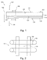
- FIG. 1 shows an air filter medium 100 with a first filter layer 110 and a second filter layer 120.
- the first filter layer 110 has a first filter layer section 111, a second filter layer section 113 and a middle section 115, with the middle section 115 being located behind the first filter layer section 111 and the second filter layer section 113 behind the middle section 115 in the direction of flow direction 103.
- the sections 111, 115, 113 are part of an integral first filter layer 110, i. H. that the first filter layer was produced in particular in one operation and was not produced from several individual layers, so that within the first filter layer or packing density jumps can be essentially prevented. Furthermore, the sections 111, 115, 113 can differ with regard to the parameters of packing density and packing density profile, with the packing density profile undergoing a change in the flow direction 103, in particular an increase.
- the first filter layer 110 has a first surface 112 and a second surface 114 .
- the first surface is designed as an inflow area of the air filter medium, which is directly exposed to the untreated air that flows from the inflow direction 102 .
- the second surface 114 adjoins the second filter layer 120 in such a way that the second surface 114 of the first filter layer 110 is in direct contact with a first surface 122 of the second filter layer 120, wherein the surface 114 can be glued to the surface 122 in particular.
- the second filter layer 120 has a second surface 124, which represents the outflow surface of the air filter medium, ie this surface 124 faces the clean side of the air filter medium, so that the clean air, starting from there, flows into the air filter medium Direction of the outflow direction 104 leaves.
- the air to be filtered flows through the air filter medium 100 transversely or orthogonally to the filter layers and filter layer sections shown.
- FIG. 2 shows a schematic representation of a fiber mesh of the first filter layer section 111.
- Four overlapping fibers 130 are shown, the fibers each having a fiber diameter or a fiber cross section 133.
- the overlapping or crossing of the fibers results in a pore 135.
- the air to be cleaned flows through the pore and dirt particles get caught on the fiber network as soon as the dimensions of a dirt particle exceed the dimensions of the pores and/or impinge on the fibers and there cling.
- FIG 3 shows an air filter medium 100 with a first filter layer 110 and a second filter layer 120, wherein the air filter medium 100 is designed as a folded filter and both filter layers 110, 120 are folded accordingly.
- the flow direction is based on the Figures 4A and 4B shown.
- Figure 4A shows an air filter medium 100, which is designed as a pleated filter with variable pleat depth 147.
- the inflow direction 102 runs in the direction of the fold depth 147.
- the fold edges 140 of all folds of the air filter medium 100 form a stepped course 145 with two different filter fold depth areas 147A, 147B, the stepped course according to the line 145 being able to be adapted to a housing shape, for example.
- the filter fold depth 147B is less than the filter fold depth 147A, as a result of which the stepped course of the fold edge line 145 results.
- the folding edge line 145 can have a linear, oblique or curved course or a combination of different shapes.
- the folded edges are at the same height.
- a stepped or differently shaped course of the folding edge line is also possible on the inflow side 102 .
- Figure 4B shows an air filter medium 100, wherein the folded edge profile 145 on the outflow side 104 has an elliptical or paraboloidal profile.
- figure 5 shows a schematic representation of an air filter medium 100 with four filter layers, the fourth filter layer 160 being arranged at the front in the flow direction 103, the third filter layer 150 directly behind the fourth filter layer 160, the first filter layer 110 directly behind the third filter layer 150 and the second filter layer 120 directly behind the first filter layer 110.
- the packing density of the filter fibers in the fourth, third and first filter layer increases with increasing material depth in the direction of flow 103, can then increase again in the second filter layer 120, which is designed as a nanofiber layer, in order to absorb dirt particles via to allow the full depth of material, which can also be referred to as volume storage.
- Figure 6A shows a schematic representation of a sectional image of an air filter medium 100 along the section line AA' 190, which is shown in 1 is shown.
- the fibers are drawn as irregular elements, with the spaces between the fibers running as a white area between the fibers. It can be seen that the number of fibers increases with increasing material depth in the direction of flow direction 103 and, conversely, the interstices become fewer and smaller. The packing density of the fibers thus increases in the direction of flow 103 and the porosity decreases to the same extent.
- FIG. 6A the third filter layer 150 and the first filter layer section 111 and the second filter layer section 113 of the first filter layer 110 are shown.
- the number of fibers and the packing density of the fibers increases in the direction 103 from the third filter layer 150 via the first filter layer 110 to the second filter layer 120 .
- Figure 6B shows a schematic representation of a sectional image of the first filter layer 110 along the section line AA′.
- the first filter layer section 111 and the second filter layer section 113 are each shown with their filter layer section depth 117 in the sectional view.
- the filter layer sections 111, 113 can have different depths 117 in the flow direction 103.
- the filter layer sections 111, 113 can be a depth section of a predetermined depth 117 in the direction of the flow direction 103 of an integral filter layer.
- Figure 6C shows a schematic representation of the first filter layer 110 with a first filter layer section 111, the depth 117 of the depth of the first filter layer section Figure 6B deviates.
- a cut through an air filter medium 100 in the direction of the cutting line 190 is to be made.
- an image recording of the cut surface can be made, which is fed to the further analysis of the packing density.
- the depth 117 and the position of a filter layer section with respect to the material depth in direction 103 on the cut surface are defined.
- the air filter medium can be impregnated with a resin, which can be made more clearly visible on an image recording by means of a marker. Such resin is in the interstices of the cross-section, but not where a fiber was actually cut when the cross-section was made.
- the fiber density can be determined on the image recording by evaluating the pixels on which a fiber can be seen and those pixels which indicate a gap. If the total number of pixels in the filter layer section is fixed or known, the packing density can be determined by relating the number of pixels showing a filter fiber to the total number of pixels in the filter layer section. Alternatively, the number of pixels showing a gap can be subtracted from the total number of pixels so as to have a control value, for example. Depending on whether the gaps or the fibers are easier to recognize and evaluate on the sectional image, the corresponding pixels can be counted.
- the packing density determined in this way is an average packing density of the evaluated filter layer section.
- the smaller such a filter sheet section is specified, i. H. the smaller the depth 117, the smaller the deviations of the packing density at the edges of the filter layer section from the mean value determined in this way.
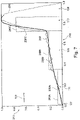
- FIG. 7 shows a schematic profile of the packing density in the first filter layer, the first filter layer being a graded filter layer with synthetic fibers.
- the representation is a normalized representation with regard to the packing density and the material thickness, i. H. the respective information on the packing density 210 is based on the highest value of the packing density in the first filter layer, the highest value being set at 1.0, or on the material thickness of the first filter layer, which is also set at 1.0.
- the absolute dimensions of the material thickness reference is made to the explanations above.
- the packing density increases in the flow direction 103, i. H. starting from a material depth of 0.0 in the direction of the maximum material thickness.
- an inflow section 107 which is very small in this exemplary embodiment and extends into the material in the flow direction up to a normalized material thickness of 0.02, the packing density increases starting at 0.0.
- the packing density increases further and increases within the first filter layer section 111 and within the central section 115 .
- the second filter layer section 113 there is a greater increase in the packing density in comparison to the sections 111, 115, until it transitions from the second filter layer section 113 into the outflow section 108, in which the packing density drops.
- a smoothed profile 230A, 230B, 230C of the packing density and an average packing density 240A, 240B, 240C are drawn in each section 111, 115, 113, the average packing density resulting from the packing density in the respective filter layer section.
- the smoothed packing density profile can be represented, for example, by means of the sliding window mechanism, in which a certain number of packing density values of adjacent subsections are used for the calculation of the smoothed packing density profile. For the next value, in one direction, e.g. B. in flow direction, a new value is added and the value that was included as the last opposite to the flow direction is omitted.
- the packing density profile 230A transitions seamlessly into the packing density profile 230B.
- the gradient of the packing density profile in the first filter layer section and in the central section can be approximately 1.
- the slope can be up to about 5.
- the first filter layer section 111 has a normalized material thickness of approximately 0.02 to approximately 0.35 and has a normalized mean packing density of approximately 0.07 to approximately 0.12.
- the middle section 115 extends from about 0.35 to about 0.73 of the normalized material thickness and has a normalized mean packing density of about 0.2 to 0.25.
- the normalized average packing density of the central section 115 is greater than the normalized average packing density of the first filter layer section 111 and lower than the normalized average packing density of the second filter layer section 112.
- the second filter sheet section extends from about 0.73 to about 0.85 of the normalized material thickness and has a normalized mean packing density of about 0.7 to 0.8.
- the result is a ratio of the normalized mean packing density of the first filter layer section 111 to a normalized mean packing density of the second filter layer section 112 of between 0.1 and 0.4, in particular between 0.1 and 0.2. A relatively strong gradient is formed.
- the curve that is actually measured can fluctuate around the smoothed value of the packing density 230A, 230B, 230C, as shown by the dotted line 250 by way of example.
- FIG. 8 shows analogous to 7 a packing density profile of a graded filter layer with cellulose-based fibers, in particular a first filter layer 110, which consists at least almost of cellulose fibers.
- the inflow section 107 can extend over the normalized material thickness of up to approximately 0.2.
- the first filter layer section 111 extends between approximately 0.2 and 0.5 of the normalized material thickness of the first filter layer.
- the normalized mean packing density is 0.35 to 0.65, specifically about 0.5
- the smoothed packing density curve extends from about 0.45 with a material thickness of 0.2 to about 0.52 with a material thickness from 0.5.
- the middle section 115 extends between about 0.5 and 0.7 of the normalized material thickness.
- the normalized mean packing density is 0.5 to 0.7, specifically about 0.6, and the smoothed packing density curve extends from about 0.52 with a material thickness of 0.5 to about 0.75 with a material thickness of 0.7 .
- the normalized average packing density of the central section 115 is greater than the normalized average packing density of the first filter layer section 111 and lower than the normalized average packing density of the second filter layer section 112.
- the second filter layer section 113 extends between approximately 0.7 and 0.8 of the normalized material thickness.
- the normalized mean packing density is about 0.9 to 0.93 and the smoothed packing density curve extends from about 0.75 with a material thickness of 0.7 to 1.0 with a material thickness of about 0.8.
- the result is a ratio of a normalized mean packing density of the first filter layer section 111 to a normalized mean packing density of the second filter layer section 112 of between 0.25 and 0.65, in particular between 0.45 and 0.60. Thanks to this Cr gradient, particularly favorable conditions arise for a cellulose-based filter layer 110 .
- the first filter layer 110 comprises at least 50% by weight cellulosic fibers and at least 25% by weight synthetic fibers.
- the ratio of a normalized average packing density of the first filter layer section 111 to a normalized average packing density of the second filter layer section 112 is between 0.25 and 0.65, preferably between 0.25 and 0.35.
- the first filter layer 110 has a middle section 115 with a normalized mean packing density that is greater than the normalized mean packing density of the first filter layer section 111 and smaller than the normalized mean packing density of the second filter layer section 112.
Landscapes
- Chemical & Material Sciences (AREA)
- Chemical Kinetics & Catalysis (AREA)
- Filtering Materials (AREA)
Claims (14)
- Elément de filtre à air avec un milieu filtrant, présentant :une première couche filtrante (110), etune deuxième couche filtrante (120),la première couche filtrante présentant une première section de couche filtrante (111) et une deuxième section de couche filtrante (113), laquelle est disposée, dans une direction de passage (103) du milieu filtrant (100), en aval de la première section de couche filtrante,la première section de couche filtrante (111) présentant un premier taux de remplissage de fibres, etla deuxième section de couche filtrante (113) présentant un deuxième taux de remplissage de fibres différent du premier taux de remplissage de fibres,la deuxième couche filtrante (120) présentant des nanofibres et étant disposée dans la direction de passage (103) en aval de la première couche filtrante (110),la première couche filtrante (110) présentant une section médiane (115), laquelle est disposée, dans la direction de passage (103), entre la première section de couche filtrante (111) et la deuxième section de couche filtrante (113),un taux de remplissage de la section médiane (115) augmentant vers la direction de passage de la première couche filtrante (110),le milieu filtrant étant un milieu filtrant plié,la deuxième couche filtrante étant disposée du côté aval de l'élément filtrant.
- Elément de filtre à air selon la revendication 1,
la première couche filtrante présentant une section de profondeur amont (107) et la première section de couche filtrante (111) étant disposée dans la direction de passage (103) en aval de la section de profondeur amont. - Elément de filtre à air selon l'une des revendications précédentes,
la section de profondeur amont étant disposée sur la première surface (112) du milieu filtrant. - Elément de filtre à air selon l'une des revendications précédentes,
la première couche filtrante présentant une section de profondeur aval (108) et la deuxième section de couche filtrante (113) étant disposée dans la direction de passage (103) en amont de la section de profondeur aval. - Elément de filtre à air selon l'une des revendications précédentes,
la deuxième couche filtrante (120) étant disposée sur une surface aval du milieu filtrant (100). - Elément de filtre à air selon l'une des revendications précédentes,la première section de couche filtrante (111) présentant un premier taux de remplissage de fibres et la deuxième section de couche filtrante (113) présentant un deuxième taux de remplissage de fibres,une valeur du deuxième taux de remplissage étant différente d'une valeur du premier taux de remplissage.
- Elément de filtre à air selon l'une des revendications précédentes,
un taux de remplissage de fibres de la première couche filtrante augmentant dans la direction de passage (103) de la première section de couche filtrante (111) vers la deuxième section de couche filtrante (113). - Elément de filtre à air selon l'une des revendications précédentes,
un taux de remplissage de la deuxième section de couche filtrante (113) étant supérieur à un taux de remplissage de la deuxième couche filtrante (120). - Elément de filtre à air selon l'une des revendications précédentes,la première section de couche filtrante (111) présentant des premières fibres avec une première section,la deuxième section de couche filtrante (113) présentant des deuxièmes fibres avec une deuxième section,la section médiane (115) présentant des premières fibres et des deuxièmes fibres.
- Elément de filtre à air selon la revendication 9,
les premières fibres et les deuxièmes fibres étant disposées dans la section médiane (115) de manière à ce qu'une partie des deuxièmes fibres augmente en comparaison avec la totalité des premières fibres et des deuxièmes fibres sur une section profonde de la première couche filtrante vers la direction de passage de la première couche filtrante. - Elément de filtre à air selon l'une des revendications précédentes,
la deuxième couche filtrante présentant une fibre d'un diamètre de fibre compris entre environ 50 nm et environ 500 nm, de préférence entre 100 nm et 300 nm. - Elément de filtre à air selon l'une des revendications précédentes,
le rapport entre un taux de remplissage moyen standardisé de la première section de couche filtrante (111) et un taux de remplissage moyen standardisé de la deuxième section de couche filtrante (112) se situant entre 0,1 et 0,4, de préférence entre 0,1 et 0,2, la première couche filtrante (110) comportant de préférence une section médiane (115) avec un taux de remplissage moyen standardisé qui est supérieur au taux de remplissage moyen standardisé de la première section de couche filtrante (111) et inférieur au taux de remplissage moyen standardisé de la deuxième section de couche filtrante (112), et de préférence la première couche filtrante étant constituée, au moins principalement, de fibres synthétiques. - Elément de filtre à air selon l'une des revendications précédentes,
le rapport entre un taux de remplissage moyen standardisé de la première section de couche filtrante (111) et un taux de remplissage moyen standardisé de la deuxième section de couche filtrante (112) se situant entre 0,25 et 0,65, de préférence entre 0,45 et 0,60, la première couche filtrante (110) comportant de préférence une section médiane (115) avec un taux de remplissage moyen standardisé qui est supérieur au taux de remplissage moyen standardisé de la première section de couche filtrante (111) et inférieur au taux de remplissage moyen standardisé de la deuxième section de couche filtrante (112) et de préférence la première couche filtrante étant constituée, au moins principalement, de fibres cellulosiques. - Elément de filtre à air selon l'une des revendications précédentes,
le rapport entre un taux de remplissage moyen standardisé de la première section de couche filtrante (111) et un taux de remplissage moyen standardisé de la deuxième section de couche filtrante (112) se situant entre 0,25 et 0,65, de préférence entre 0,25 et 0,35, de préférence la première couche filtrante (110) comportant une section médiane (115) avec un taux de remplissage moyen standardisé qui est supérieur au taux de remplissage moyen standardisé de la première section de couche filtrante (111) et inférieur au taux de remplissage moyen standardisé de la deuxième section de couche filtrante (112), et de préférence la première couche filtrante étant constituée d'au moins 50 pour-cent en poids de fibres cellulosiques et d'au moins 25 pour-cent en poids de fibres synthétiques.
Priority Applications (3)
| Application Number | Priority Date | Filing Date | Title |
|---|---|---|---|
| PL17171817T PL3231497T3 (pl) | 2013-04-23 | 2014-04-15 | Medium filtracyjne, zwłaszcza medium filtracyjne powietrza oraz element filtracyjny, zwłaszcza element filtracyjny powietrza, z medium filtracyjnym |
| EP17171817.4A EP3231497B1 (fr) | 2013-04-23 | 2014-04-15 | Milieu filtrant, en particulier milieu de filtre à air et élément de filtre, en particulier élément de filtre à air, pourvu d'un milieu filtrant |
| EP19178002.2A EP3552683A1 (fr) | 2013-04-23 | 2014-04-15 | Milieu filtrant, en particulier milieu de filtre à air et élément de filtre, en particulier élément de filtre à air, pourvu d'un milieu filtrant |
Applications Claiming Priority (3)
| Application Number | Priority Date | Filing Date | Title |
|---|---|---|---|
| DE102013006952 | 2013-04-23 | ||
| DE102013008391.5A DE102013008391A1 (de) | 2013-04-23 | 2013-05-17 | Filtermedium, insbesondere Luftfiltermedium, sowie Filterelement, insbesondere Luftfilterelement, mit einem Filtermedium |
| PCT/EP2014/057631 WO2014173733A1 (fr) | 2013-04-23 | 2014-04-15 | Milieu filtrant, en particulier milieu de filtre à air et élément de filtre, en particulier élément de filtre à air, pourvu d'un milieu filtrant |
Related Child Applications (4)
| Application Number | Title | Priority Date | Filing Date |
|---|---|---|---|
| EP19178002.2A Division-Into EP3552683A1 (fr) | 2013-04-23 | 2014-04-15 | Milieu filtrant, en particulier milieu de filtre à air et élément de filtre, en particulier élément de filtre à air, pourvu d'un milieu filtrant |
| EP19178002.2A Division EP3552683A1 (fr) | 2013-04-23 | 2014-04-15 | Milieu filtrant, en particulier milieu de filtre à air et élément de filtre, en particulier élément de filtre à air, pourvu d'un milieu filtrant |
| EP17171817.4A Division EP3231497B1 (fr) | 2013-04-23 | 2014-04-15 | Milieu filtrant, en particulier milieu de filtre à air et élément de filtre, en particulier élément de filtre à air, pourvu d'un milieu filtrant |
| EP17171817.4A Division-Into EP3231497B1 (fr) | 2013-04-23 | 2014-04-15 | Milieu filtrant, en particulier milieu de filtre à air et élément de filtre, en particulier élément de filtre à air, pourvu d'un milieu filtrant |
Publications (3)
| Publication Number | Publication Date |
|---|---|
| EP2988846A1 EP2988846A1 (fr) | 2016-03-02 |
| EP2988846B1 EP2988846B1 (fr) | 2017-05-31 |
| EP2988846B2 true EP2988846B2 (fr) | 2023-01-18 |
Family
ID=51628777
Family Applications (3)
| Application Number | Title | Priority Date | Filing Date |
|---|---|---|---|
| EP19178002.2A Withdrawn EP3552683A1 (fr) | 2013-04-23 | 2014-04-15 | Milieu filtrant, en particulier milieu de filtre à air et élément de filtre, en particulier élément de filtre à air, pourvu d'un milieu filtrant |
| EP17171817.4A Active EP3231497B1 (fr) | 2013-04-23 | 2014-04-15 | Milieu filtrant, en particulier milieu de filtre à air et élément de filtre, en particulier élément de filtre à air, pourvu d'un milieu filtrant |
| EP14718378.4A Active EP2988846B2 (fr) | 2013-04-23 | 2014-04-15 | Milieu filtrant, en particulier milieu de filtre à air et élément de filtre, en particulier élément de filtre à air, pourvu d'un milieu filtrant |
Family Applications Before (2)
| Application Number | Title | Priority Date | Filing Date |
|---|---|---|---|
| EP19178002.2A Withdrawn EP3552683A1 (fr) | 2013-04-23 | 2014-04-15 | Milieu filtrant, en particulier milieu de filtre à air et élément de filtre, en particulier élément de filtre à air, pourvu d'un milieu filtrant |
| EP17171817.4A Active EP3231497B1 (fr) | 2013-04-23 | 2014-04-15 | Milieu filtrant, en particulier milieu de filtre à air et élément de filtre, en particulier élément de filtre à air, pourvu d'un milieu filtrant |
Country Status (6)
| Country | Link |
|---|---|
| US (1) | US20160051918A1 (fr) |
| EP (3) | EP3552683A1 (fr) |
| CN (2) | CN105120979B (fr) |
| DE (2) | DE102013008391A1 (fr) |
| PL (1) | PL3231497T3 (fr) |
| WO (1) | WO2014173733A1 (fr) |
Families Citing this family (17)
| Publication number | Priority date | Publication date | Assignee | Title |
|---|---|---|---|---|
| US10828587B2 (en) | 2015-04-17 | 2020-11-10 | Hollingsworth & Vose Company | Stable filter media including nanofibers |
| DE102015012643A1 (de) | 2015-09-30 | 2017-03-30 | Mann + Hummel Gmbh | Filtermedium und Verwendung des Filtermediums |
| CN109562311B (zh) | 2016-05-13 | 2021-07-16 | 唐纳森公司 | 过滤介质、过滤元件和过滤方法 |
| WO2018011347A1 (fr) * | 2016-07-14 | 2018-01-18 | Ahlstrom-Munksjö Oyj | Milieu filtrant ayant une efficacité améliorée pour l'élimination des particules de carburant |
| US20180133632A1 (en) * | 2016-11-11 | 2018-05-17 | Hollingsworth & Vose Company | Filter media having a density variation |
| CN107362618B (zh) * | 2017-08-22 | 2019-09-13 | 江南大学 | 具有高容污及吸附功能的折叠滤芯及其制备方法 |
| EP3810304A1 (fr) * | 2018-06-25 | 2021-04-28 | Zephyros, Inc. | Insert fonctionnel pour matériaux non tissés |
| US11452959B2 (en) * | 2018-11-30 | 2022-09-27 | Hollingsworth & Vose Company | Filter media having a fine pore size distribution |
| DE102018130552A1 (de) * | 2018-11-30 | 2020-06-04 | Mann+Hummel Gmbh | Flüssigkeitsfilter |
| CN114040811A (zh) | 2019-03-28 | 2022-02-11 | 唐纳森公司 | 具有改进的灰尘负载的过滤介质 |
| US11213777B2 (en) | 2019-09-06 | 2022-01-04 | Imam Abdulrahman Bin Faisal University | Titanium oxide-comprising fibrous filter material |
| CN114938636A (zh) | 2019-10-08 | 2022-08-23 | 唐纳森公司 | 包括混合直径细纤维的过滤介质层 |
| DE102019129776B3 (de) * | 2019-11-05 | 2021-01-21 | Mann+Hummel Gmbh | Filtermedium, Verfahren zu dessen Herstellung und Verwendung des Filtermediums in einem Filterelement |
| KR102893058B1 (ko) * | 2020-02-11 | 2025-12-01 | 삼성전자주식회사 | 전자 부품의 열을 방출할 수 있는 전자파 차폐 시트 및 그 것을 포함하는 전자 장치 |
| JP7738556B2 (ja) | 2020-04-03 | 2025-09-12 | ドナルドソン カンパニー,インコーポレイティド | 濾過媒体 |
| CN218339211U (zh) * | 2022-11-01 | 2023-01-20 | 马勒汽车技术(中国)有限公司 | 滤芯及具有该滤芯的汽车空调过滤器 |
| US20250099887A1 (en) * | 2023-02-06 | 2025-03-27 | Fibertex Nonwovens A/S | Filter material comprising a gradient structure nonwoven base layer and a nanofiber top layer |
Family Cites Families (28)
| Publication number | Priority date | Publication date | Assignee | Title |
|---|---|---|---|---|
| US4032688A (en) * | 1973-08-31 | 1977-06-28 | Pall Corporation | Seamless tubular nonwoven webs and filters thereof |
| US4842739A (en) * | 1987-08-20 | 1989-06-27 | Minnesota Mining And Manufacturing Company | High surface area filter cartridge |
| WO1990010487A1 (fr) * | 1989-03-16 | 1990-09-20 | Toyo Boseki Kabushiki Kaisha | Milieu filtrant tubulaire flexible |
| IN189834B (fr) * | 1997-04-18 | 2003-04-26 | Mann & Hummel Filter | |
| WO1999064676A1 (fr) * | 1998-06-10 | 1999-12-16 | Bba Nonwovens Simpsonville, Inc. | Filtre a lait obtenu au mouille lie thermiquement haute efficacite |
| DE19920983C5 (de) * | 1999-05-06 | 2004-11-18 | Fibermark Gessner Gmbh & Co. Ohg | Zwei- oder mehrlagiges Filtermedium für die Luftfiltration und daraus hergestelltes Filterelement |
| KR100405318B1 (ko) | 2000-11-20 | 2003-11-12 | 한국바이린주식회사 | 공기 청정기용 필터 여재와 그 제조방법 |
| DE10245124A1 (de) * | 2002-09-27 | 2004-02-05 | Fibermark Gessner Gmbh & Co. Ohg | Filtermedium für die Flüssigkeitsfiltration mit erhöhter Standzeit |
| DE102006048076A1 (de) | 2006-10-09 | 2008-04-10 | Mann + Hummel Gmbh | Filtereinrichtung, insbesondere zur Filtration von Verbrennungsluft in Brennkraftmaschinen |
| US7717975B2 (en) | 2005-02-16 | 2010-05-18 | Donaldson Company, Inc. | Reduced solidity web comprising fiber and fiber spacer or separation means |
| WO2006106506A2 (fr) * | 2005-04-04 | 2006-10-12 | Technion Research & Development Foundation Ltd. | Structure medicale d'accrochage, procedes de fabrication et d'utilisation de cette derniere |
| DE202005019004U1 (de) | 2005-12-06 | 2007-04-19 | Melitta Haushaltsprodukte Gmbh & Co. Kg | Filtermaterial und Staubsaugerbeutel |
| US8062523B2 (en) | 2006-12-01 | 2011-11-22 | Perry Equipment Corporation | Filter element and methods of manufacturing and using same |
| US8231013B2 (en) | 2006-12-05 | 2012-07-31 | The Research Foundation Of State University Of New York | Articles comprising a fibrous support |
| US8257459B2 (en) | 2007-02-28 | 2012-09-04 | Hollingsworth & Vose Company | Waved filter media and elements |
| DE202007005847U1 (de) | 2007-04-20 | 2007-08-02 | Wolf Gmbh & Co. Kg | Filterbeutel für einen Staubsauger |
| KR101000366B1 (ko) | 2007-04-25 | 2010-12-13 | 비엔케이(주) | 공기 청정용 필터 |
| US8303693B2 (en) * | 2007-04-26 | 2012-11-06 | The Hong Kong Polytechnic University | Nanofiber filter facemasks and cabin filters |
| DE202007018375U1 (de) * | 2007-07-06 | 2008-07-03 | Eurofilters Holding N.V. | Staubsaugerfilterbeutel |
| DE202007015659U1 (de) * | 2007-11-08 | 2009-03-19 | Mann+Hummel Gmbh | Mehrlagiges, insbesondere zweistufiges Filterelement zur Reinigung eines mit Partikeln behafteten Mediums |
| WO2009064311A1 (fr) * | 2007-11-13 | 2009-05-22 | E. I. Du Pont De Nemours And Company | Vêtement pouvant respirer comportant une couche d'évacuation de fluide |
| DE202007015994U1 (de) | 2007-11-14 | 2008-01-17 | Wolf Pvg Gmbh & Co. Kg | Luftfiltermedium |
| US20110064928A1 (en) * | 2008-05-05 | 2011-03-17 | Avgol Industries 1953 Ltd | Nonwoven material |
| US20110114554A1 (en) | 2008-07-18 | 2011-05-19 | Clarcor Inc. | Multi-component filter media with nanofiber attachment |
| US7922959B2 (en) * | 2008-08-01 | 2011-04-12 | E. I. Du Pont De Nemours And Company | Method of manufacturing a composite filter media |
| US8267681B2 (en) * | 2009-01-28 | 2012-09-18 | Donaldson Company, Inc. | Method and apparatus for forming a fibrous media |
| US8679218B2 (en) * | 2010-04-27 | 2014-03-25 | Hollingsworth & Vose Company | Filter media with a multi-layer structure |
| DE102011111738A1 (de) * | 2011-08-26 | 2013-02-28 | Neenah Gessner Gmbh | Mehrlagiges Filtermaterial und daraus hergestelltes Filterelement |
-
2013
- 2013-05-17 DE DE102013008391.5A patent/DE102013008391A1/de not_active Withdrawn
-
2014
- 2014-04-15 PL PL17171817T patent/PL3231497T3/pl unknown
- 2014-04-15 DE DE112014002098.2T patent/DE112014002098A5/de not_active Ceased
- 2014-04-15 CN CN201480023191.1A patent/CN105120979B/zh not_active Expired - Fee Related
- 2014-04-15 EP EP19178002.2A patent/EP3552683A1/fr not_active Withdrawn
- 2014-04-15 EP EP17171817.4A patent/EP3231497B1/fr active Active
- 2014-04-15 CN CN201711155957.3A patent/CN107823961B/zh active Active
- 2014-04-15 EP EP14718378.4A patent/EP2988846B2/fr active Active
- 2014-04-15 WO PCT/EP2014/057631 patent/WO2014173733A1/fr not_active Ceased
-
2015
- 2015-10-23 US US14/922,063 patent/US20160051918A1/en not_active Abandoned
Also Published As
| Publication number | Publication date |
|---|---|
| CN105120979B (zh) | 2017-12-19 |
| CN107823961B (zh) | 2020-03-13 |
| EP3231497B1 (fr) | 2019-06-05 |
| EP2988846B1 (fr) | 2017-05-31 |
| CN105120979A (zh) | 2015-12-02 |
| DE102013008391A1 (de) | 2014-10-23 |
| US20160051918A1 (en) | 2016-02-25 |
| PL3231497T3 (pl) | 2019-12-31 |
| EP2988846A1 (fr) | 2016-03-02 |
| DE112014002098A5 (de) | 2016-01-14 |
| WO2014173733A1 (fr) | 2014-10-30 |
| CN107823961A (zh) | 2018-03-23 |
| EP3231497A1 (fr) | 2017-10-18 |
| EP3552683A1 (fr) | 2019-10-16 |
Similar Documents
| Publication | Publication Date | Title |
|---|---|---|
| EP2988846B2 (fr) | Milieu filtrant, en particulier milieu de filtre à air et élément de filtre, en particulier élément de filtre à air, pourvu d'un milieu filtrant | |
| EP2544791B1 (fr) | Matériau filtrant d'un élément filtrant et un élément filtrant | |
| DE10221694B4 (de) | Mehrlagiger Filteraufbau, Verwendung eines solchen mehrlagigen Filteraufbaus, Staubfilterbeutel, Taschenfilterbeutel, plissierter Filter, flächiger Abluftfilter und Luftfilter für Kraftfahrzeuge | |
| EP0338479B1 (fr) | Sac de filtration de poussière, fabrication et emploi | |
| EP2911765B1 (fr) | Matériau de filtre à durée d'utilisation accrue et élément filtrant contenant ce matériau de filtre | |
| DE102012010307B4 (de) | Mehrlagiges Filtermaterial zur Flüssigkeitsfiltration sowie daraus hergestelltes Filterelement | |
| EP1035902A1 (fr) | Element filtrant | |
| DE112019002280T5 (de) | Verbundfiltermedien mit mehreren faserstrukturen einschliesslich nanofasern | |
| DE102008035934B4 (de) | Filtermedium | |
| EP1791617B1 (fr) | Procede de production d'une couche filtrante et couche filtrante destinee en particulier a un sac filtre a poussiere d'un aspirateur | |
| EP2777795B1 (fr) | Sac d'aspirateur | |
| WO2015091011A1 (fr) | Milieu de filtrage et élément de filtrage présentant un milieu de filtrage | |
| DE102015015777A1 (de) | Filtermedium und Filterelement mit einem Filtermedium | |
| DE20207663U1 (de) | Mehrlagiger Filteraufbau | |
| DE9218021U1 (de) | Mehrschichtiges Filtermaterial | |
| EP3049171B1 (fr) | Matériau filtrant et combinaison de matériaux filtrants servant à isoler des liquides et éléments filtrants fabriqués à partir dudit matériau filtrant | |
| EP3630335B1 (fr) | Milieu filtrant, son procédé de fabrication et son utilisation dans un élément filtrant | |
| WO2017063794A1 (fr) | Élément de coalescence et élément filtrant présentant un élément de coalescence | |
| EP3601657B1 (fr) | Média filtrant, élément filtrant et leur utilisation, et système filtrant | |
| DE10392265T5 (de) | Luftreinigerelement |
Legal Events
| Date | Code | Title | Description |
|---|---|---|---|
| PUAI | Public reference made under article 153(3) epc to a published international application that has entered the european phase |
Free format text: ORIGINAL CODE: 0009012 |
|
| 17P | Request for examination filed |
Effective date: 20151020 |
|
| AK | Designated contracting states |
Kind code of ref document: A1 Designated state(s): AL AT BE BG CH CY CZ DE DK EE ES FI FR GB GR HR HU IE IS IT LI LT LU LV MC MK MT NL NO PL PT RO RS SE SI SK SM TR |
|
| AX | Request for extension of the european patent |
Extension state: BA ME |
|
| RIN1 | Information on inventor provided before grant (corrected) |
Inventor name: POLJAK, IVANKA Inventor name: WALZ, STEFAN Inventor name: MBADINGA MOUANDA, GELASE Inventor name: HEIM, MICHAEL Inventor name: NEUMANN, JENS Inventor name: KILIAN, ALEXANDER Inventor name: PFANNKUCH, STEFFEN Inventor name: KELLER, MARIO |
|
| DAX | Request for extension of the european patent (deleted) | ||
| GRAP | Despatch of communication of intention to grant a patent |
Free format text: ORIGINAL CODE: EPIDOSNIGR1 |
|
| STAA | Information on the status of an ep patent application or granted ep patent |
Free format text: STATUS: GRANT OF PATENT IS INTENDED |
|
| INTG | Intention to grant announced |
Effective date: 20161214 |
|
| GRAS | Grant fee paid |
Free format text: ORIGINAL CODE: EPIDOSNIGR3 |
|
| GRAA | (expected) grant |
Free format text: ORIGINAL CODE: 0009210 |
|
| STAA | Information on the status of an ep patent application or granted ep patent |
Free format text: STATUS: THE PATENT HAS BEEN GRANTED |
|
| AK | Designated contracting states |
Kind code of ref document: B1 Designated state(s): AL AT BE BG CH CY CZ DE DK EE ES FI FR GB GR HR HU IE IS IT LI LT LU LV MC MK MT NL NO PL PT RO RS SE SI SK SM TR |
|
| REG | Reference to a national code |
Ref country code: CH Ref legal event code: EP Ref country code: GB Ref legal event code: FG4D Free format text: NOT ENGLISH |
|
| REG | Reference to a national code |
Ref country code: AT Ref legal event code: REF Ref document number: 896917 Country of ref document: AT Kind code of ref document: T Effective date: 20170615 |
|
| REG | Reference to a national code |
Ref country code: IE Ref legal event code: FG4D Free format text: LANGUAGE OF EP DOCUMENT: GERMAN |
|
| REG | Reference to a national code |
Ref country code: DE Ref legal event code: R096 Ref document number: 502014004006 Country of ref document: DE |
|
| REG | Reference to a national code |
Ref country code: NL Ref legal event code: MP Effective date: 20170531 |
|
| REG | Reference to a national code |
Ref country code: LT Ref legal event code: MG4D |
|
| PG25 | Lapsed in a contracting state [announced via postgrant information from national office to epo] |
Ref country code: GR Free format text: LAPSE BECAUSE OF FAILURE TO SUBMIT A TRANSLATION OF THE DESCRIPTION OR TO PAY THE FEE WITHIN THE PRESCRIBED TIME-LIMIT Effective date: 20170901 Ref country code: ES Free format text: LAPSE BECAUSE OF FAILURE TO SUBMIT A TRANSLATION OF THE DESCRIPTION OR TO PAY THE FEE WITHIN THE PRESCRIBED TIME-LIMIT Effective date: 20170531 Ref country code: LT Free format text: LAPSE BECAUSE OF FAILURE TO SUBMIT A TRANSLATION OF THE DESCRIPTION OR TO PAY THE FEE WITHIN THE PRESCRIBED TIME-LIMIT Effective date: 20170531 Ref country code: FI Free format text: LAPSE BECAUSE OF FAILURE TO SUBMIT A TRANSLATION OF THE DESCRIPTION OR TO PAY THE FEE WITHIN THE PRESCRIBED TIME-LIMIT Effective date: 20170531 Ref country code: NO Free format text: LAPSE BECAUSE OF FAILURE TO SUBMIT A TRANSLATION OF THE DESCRIPTION OR TO PAY THE FEE WITHIN THE PRESCRIBED TIME-LIMIT Effective date: 20170831 Ref country code: HR Free format text: LAPSE BECAUSE OF FAILURE TO SUBMIT A TRANSLATION OF THE DESCRIPTION OR TO PAY THE FEE WITHIN THE PRESCRIBED TIME-LIMIT Effective date: 20170531 |
|
| PG25 | Lapsed in a contracting state [announced via postgrant information from national office to epo] |
Ref country code: SE Free format text: LAPSE BECAUSE OF FAILURE TO SUBMIT A TRANSLATION OF THE DESCRIPTION OR TO PAY THE FEE WITHIN THE PRESCRIBED TIME-LIMIT Effective date: 20170531 Ref country code: RS Free format text: LAPSE BECAUSE OF FAILURE TO SUBMIT A TRANSLATION OF THE DESCRIPTION OR TO PAY THE FEE WITHIN THE PRESCRIBED TIME-LIMIT Effective date: 20170531 Ref country code: BG Free format text: LAPSE BECAUSE OF FAILURE TO SUBMIT A TRANSLATION OF THE DESCRIPTION OR TO PAY THE FEE WITHIN THE PRESCRIBED TIME-LIMIT Effective date: 20170831 Ref country code: NL Free format text: LAPSE BECAUSE OF FAILURE TO SUBMIT A TRANSLATION OF THE DESCRIPTION OR TO PAY THE FEE WITHIN THE PRESCRIBED TIME-LIMIT Effective date: 20170531 Ref country code: LV Free format text: LAPSE BECAUSE OF FAILURE TO SUBMIT A TRANSLATION OF THE DESCRIPTION OR TO PAY THE FEE WITHIN THE PRESCRIBED TIME-LIMIT Effective date: 20170531 Ref country code: IS Free format text: LAPSE BECAUSE OF FAILURE TO SUBMIT A TRANSLATION OF THE DESCRIPTION OR TO PAY THE FEE WITHIN THE PRESCRIBED TIME-LIMIT Effective date: 20170930 |
|
| PG25 | Lapsed in a contracting state [announced via postgrant information from national office to epo] |
Ref country code: SK Free format text: LAPSE BECAUSE OF FAILURE TO SUBMIT A TRANSLATION OF THE DESCRIPTION OR TO PAY THE FEE WITHIN THE PRESCRIBED TIME-LIMIT Effective date: 20170531 Ref country code: RO Free format text: LAPSE BECAUSE OF FAILURE TO SUBMIT A TRANSLATION OF THE DESCRIPTION OR TO PAY THE FEE WITHIN THE PRESCRIBED TIME-LIMIT Effective date: 20170531 Ref country code: EE Free format text: LAPSE BECAUSE OF FAILURE TO SUBMIT A TRANSLATION OF THE DESCRIPTION OR TO PAY THE FEE WITHIN THE PRESCRIBED TIME-LIMIT Effective date: 20170531 Ref country code: CZ Free format text: LAPSE BECAUSE OF FAILURE TO SUBMIT A TRANSLATION OF THE DESCRIPTION OR TO PAY THE FEE WITHIN THE PRESCRIBED TIME-LIMIT Effective date: 20170531 Ref country code: DK Free format text: LAPSE BECAUSE OF FAILURE TO SUBMIT A TRANSLATION OF THE DESCRIPTION OR TO PAY THE FEE WITHIN THE PRESCRIBED TIME-LIMIT Effective date: 20170531 |
|
| PG25 | Lapsed in a contracting state [announced via postgrant information from national office to epo] |
Ref country code: SM Free format text: LAPSE BECAUSE OF FAILURE TO SUBMIT A TRANSLATION OF THE DESCRIPTION OR TO PAY THE FEE WITHIN THE PRESCRIBED TIME-LIMIT Effective date: 20170531 Ref country code: PL Free format text: LAPSE BECAUSE OF FAILURE TO SUBMIT A TRANSLATION OF THE DESCRIPTION OR TO PAY THE FEE WITHIN THE PRESCRIBED TIME-LIMIT Effective date: 20170531 |
|
| REG | Reference to a national code |
Ref country code: DE Ref legal event code: R026 Ref document number: 502014004006 Country of ref document: DE |
|
| PLBI | Opposition filed |
Free format text: ORIGINAL CODE: 0009260 |
|
| PLAX | Notice of opposition and request to file observation + time limit sent |
Free format text: ORIGINAL CODE: EPIDOSNOBS2 |
|
| 26 | Opposition filed |
Opponent name: MAHLE INTERNATIONAL GMBH Effective date: 20180228 |
|
| REG | Reference to a national code |
Ref country code: FR Ref legal event code: PLFP Year of fee payment: 5 |
|
| PG25 | Lapsed in a contracting state [announced via postgrant information from national office to epo] |
Ref country code: SI Free format text: LAPSE BECAUSE OF FAILURE TO SUBMIT A TRANSLATION OF THE DESCRIPTION OR TO PAY THE FEE WITHIN THE PRESCRIBED TIME-LIMIT Effective date: 20170531 |
|
| REG | Reference to a national code |
Ref country code: DE Ref legal event code: R081 Ref document number: 502014004006 Country of ref document: DE Owner name: MANN+HUMMEL GMBH, DE Free format text: FORMER OWNER: MANN + HUMMEL GMBH, 71638 LUDWIGSBURG, DE |
|
| PLBB | Reply of patent proprietor to notice(s) of opposition received |
Free format text: ORIGINAL CODE: EPIDOSNOBS3 |
|
| PG25 | Lapsed in a contracting state [announced via postgrant information from national office to epo] |
Ref country code: MT Free format text: LAPSE BECAUSE OF FAILURE TO SUBMIT A TRANSLATION OF THE DESCRIPTION OR TO PAY THE FEE WITHIN THE PRESCRIBED TIME-LIMIT Effective date: 20170531 |
|
| PG25 | Lapsed in a contracting state [announced via postgrant information from national office to epo] |
Ref country code: MC Free format text: LAPSE BECAUSE OF FAILURE TO SUBMIT A TRANSLATION OF THE DESCRIPTION OR TO PAY THE FEE WITHIN THE PRESCRIBED TIME-LIMIT Effective date: 20170531 |
|
| REG | Reference to a national code |
Ref country code: CH Ref legal event code: PL |
|
| REG | Reference to a national code |
Ref country code: BE Ref legal event code: MM Effective date: 20180430 |
|
| GBPC | Gb: european patent ceased through non-payment of renewal fee |
Effective date: 20180415 |
|
| REG | Reference to a national code |
Ref country code: IE Ref legal event code: MM4A |
|
| PG25 | Lapsed in a contracting state [announced via postgrant information from national office to epo] |
Ref country code: LU Free format text: LAPSE BECAUSE OF NON-PAYMENT OF DUE FEES Effective date: 20180415 |
|
| PG25 | Lapsed in a contracting state [announced via postgrant information from national office to epo] |
Ref country code: BE Free format text: LAPSE BECAUSE OF NON-PAYMENT OF DUE FEES Effective date: 20180430 Ref country code: GB Free format text: LAPSE BECAUSE OF NON-PAYMENT OF DUE FEES Effective date: 20180415 Ref country code: LI Free format text: LAPSE BECAUSE OF NON-PAYMENT OF DUE FEES Effective date: 20180430 Ref country code: CH Free format text: LAPSE BECAUSE OF NON-PAYMENT OF DUE FEES Effective date: 20180430 |
|
| PG25 | Lapsed in a contracting state [announced via postgrant information from national office to epo] |
Ref country code: IE Free format text: LAPSE BECAUSE OF NON-PAYMENT OF DUE FEES Effective date: 20180415 |
|
| APBM | Appeal reference recorded |
Free format text: ORIGINAL CODE: EPIDOSNREFNO |
|
| APBP | Date of receipt of notice of appeal recorded |
Free format text: ORIGINAL CODE: EPIDOSNNOA2O |
|
| APAH | Appeal reference modified |
Free format text: ORIGINAL CODE: EPIDOSCREFNO |
|
| APBM | Appeal reference recorded |
Free format text: ORIGINAL CODE: EPIDOSNREFNO |
|
| APBP | Date of receipt of notice of appeal recorded |
Free format text: ORIGINAL CODE: EPIDOSNNOA2O |
|
| APAH | Appeal reference modified |
Free format text: ORIGINAL CODE: EPIDOSCREFNO |
|
| APBQ | Date of receipt of statement of grounds of appeal recorded |
Free format text: ORIGINAL CODE: EPIDOSNNOA3O |
|
| APBQ | Date of receipt of statement of grounds of appeal recorded |
Free format text: ORIGINAL CODE: EPIDOSNNOA3O |
|
| PG25 | Lapsed in a contracting state [announced via postgrant information from national office to epo] |
Ref country code: TR Free format text: LAPSE BECAUSE OF FAILURE TO SUBMIT A TRANSLATION OF THE DESCRIPTION OR TO PAY THE FEE WITHIN THE PRESCRIBED TIME-LIMIT Effective date: 20170531 |
|
| PG25 | Lapsed in a contracting state [announced via postgrant information from national office to epo] |
Ref country code: PT Free format text: LAPSE BECAUSE OF FAILURE TO SUBMIT A TRANSLATION OF THE DESCRIPTION OR TO PAY THE FEE WITHIN THE PRESCRIBED TIME-LIMIT Effective date: 20170531 |
|
| PG25 | Lapsed in a contracting state [announced via postgrant information from national office to epo] |
Ref country code: HU Free format text: LAPSE BECAUSE OF FAILURE TO SUBMIT A TRANSLATION OF THE DESCRIPTION OR TO PAY THE FEE WITHIN THE PRESCRIBED TIME-LIMIT; INVALID AB INITIO Effective date: 20140415 Ref country code: MK Free format text: LAPSE BECAUSE OF NON-PAYMENT OF DUE FEES Effective date: 20170531 Ref country code: CY Free format text: LAPSE BECAUSE OF FAILURE TO SUBMIT A TRANSLATION OF THE DESCRIPTION OR TO PAY THE FEE WITHIN THE PRESCRIBED TIME-LIMIT Effective date: 20170531 |
|
| PG25 | Lapsed in a contracting state [announced via postgrant information from national office to epo] |
Ref country code: AL Free format text: LAPSE BECAUSE OF FAILURE TO SUBMIT A TRANSLATION OF THE DESCRIPTION OR TO PAY THE FEE WITHIN THE PRESCRIBED TIME-LIMIT Effective date: 20170531 |
|
| RAP4 | Party data changed (patent owner data changed or rights of a patent transferred) |
Owner name: MANN+HUMMEL GMBH |
|
| APBU | Appeal procedure closed |
Free format text: ORIGINAL CODE: EPIDOSNNOA9O |
|
| PUAH | Patent maintained in amended form |
Free format text: ORIGINAL CODE: 0009272 |
|
| STAA | Information on the status of an ep patent application or granted ep patent |
Free format text: STATUS: PATENT MAINTAINED AS AMENDED |
|
| 27A | Patent maintained in amended form |
Effective date: 20230118 |
|
| AK | Designated contracting states |
Kind code of ref document: B2 Designated state(s): AL AT BE BG CH CY CZ DE DK EE ES FI FR GB GR HR HU IE IS IT LI LT LU LV MC MK MT NL NO PL PT RO RS SE SI SK SM TR |
|
| REG | Reference to a national code |
Ref country code: DE Ref legal event code: R102 Ref document number: 502014004006 Country of ref document: DE |
|
| P01 | Opt-out of the competence of the unified patent court (upc) registered |
Effective date: 20230530 |
|
| PGFP | Annual fee paid to national office [announced via postgrant information from national office to epo] |
Ref country code: DE Payment date: 20250422 Year of fee payment: 12 |
|
| PGFP | Annual fee paid to national office [announced via postgrant information from national office to epo] |
Ref country code: IT Payment date: 20250424 Year of fee payment: 12 |
|
| PGFP | Annual fee paid to national office [announced via postgrant information from national office to epo] |
Ref country code: FR Payment date: 20250425 Year of fee payment: 12 |
|
| PGFP | Annual fee paid to national office [announced via postgrant information from national office to epo] |
Ref country code: AT Payment date: 20250423 Year of fee payment: 12 |