EP2988848B1 - Dispositif de filtre à air - Google Patents
Dispositif de filtre à air Download PDFInfo
- Publication number
- EP2988848B1 EP2988848B1 EP14716603.7A EP14716603A EP2988848B1 EP 2988848 B1 EP2988848 B1 EP 2988848B1 EP 14716603 A EP14716603 A EP 14716603A EP 2988848 B1 EP2988848 B1 EP 2988848B1
- Authority
- EP
- European Patent Office
- Prior art keywords
- support frame
- functional part
- filter
- functional
- frame
- Prior art date
- Legal status (The legal status is an assumption and is not a legal conclusion. Google has not performed a legal analysis and makes no representation as to the accuracy of the status listed.)
- Not-in-force
Links
Images

Classifications
-
- B—PERFORMING OPERATIONS; TRANSPORTING
- B01—PHYSICAL OR CHEMICAL PROCESSES OR APPARATUS IN GENERAL
- B01D—SEPARATION
- B01D46/00—Filters or filtering processes specially modified for separating dispersed particles from gases or vapours
- B01D46/0039—Filters or filtering processes specially modified for separating dispersed particles from gases or vapours with flow guiding by feed or discharge devices
- B01D46/0047—Filters or filtering processes specially modified for separating dispersed particles from gases or vapours with flow guiding by feed or discharge devices for discharging the filtered gas
- B01D46/0049—Filters or filtering processes specially modified for separating dispersed particles from gases or vapours with flow guiding by feed or discharge devices for discharging the filtered gas containing fixed gas displacement elements or cores
-
- B—PERFORMING OPERATIONS; TRANSPORTING
- B01—PHYSICAL OR CHEMICAL PROCESSES OR APPARATUS IN GENERAL
- B01D—SEPARATION
- B01D46/00—Filters or filtering processes specially modified for separating dispersed particles from gases or vapours
- B01D46/10—Particle separators, e.g. dust precipitators, using filter plates, sheets or pads having plane surfaces
-
- B—PERFORMING OPERATIONS; TRANSPORTING
- B01—PHYSICAL OR CHEMICAL PROCESSES OR APPARATUS IN GENERAL
- B01D—SEPARATION
- B01D2271/00—Sealings for filters specially adapted for separating dispersed particles from gases or vapours
- B01D2271/02—Gaskets, sealings
- B01D2271/022—Axial sealings
Definitions
- the present invention relates to a filter element for an air filter device of a fresh air system of an internal combustion engine, in particular of a motor vehicle, with the features of the preamble of claim 1.
- the invention also relates to a combination of such a filter element with a functional part.
- the invention also relates to an air filter device for a fresh air system of an internal combustion engine, in particular of a motor vehicle, which is equipped with such a filter element or with such a combination.
- the invention also relates to a modular system for producing such combinations.
- the pamphlet DE102010045985 A1 describes the air supply to an internal combustion engine, the air intake tract containing an air filter, an air guide element and an air mass sensor.
- an air filter device for a fresh air system of an internal combustion engine which contains a filter element in a housing which has a filter body made of a filter material and a sealing frame made of a sealing material.
- the sealing frame has a filter section assigned to the filter body and surrounds the filter body on the edge, closed circumferentially.
- the known filter element also has a functional part through which air can flow in the form of a grille, which is enclosed by a functional section of the sealing frame on the edge, closed circumferentially.
- the filter body and the functional part are firmly connected to the sealing frame, in particular embedded therein at the edge.
- an air inlet opening and / or an air outlet opening can be oriented differently.
- the present invention deals with the problem of showing a way for a filter element of the type mentioned at the beginning which simplifies adaptation to different configurations of an air filter device.
- the invention is based on the general idea of equipping the filter element with a support frame which is designed to attach a functional part to it.
- the support frame is now for its part enclosed by a functional section of the sealing frame on the edge, closed circumferentially.
- the support frame itself encloses a functional part opening in a closed circumferential manner.
- the filter element according to the invention integrates a support frame into the sealing frame, which makes it possible to attach different functional parts to the support frame. In this way, the filter element can be equipped with a suitable functional part as required, which simplifies the adaptation of the filter element to different applications.
- the respective functional part is a separate component with respect to the support frame.
- the functional part opening is completely open.
- the entire functional part opening is thus available for inserting a functional part, since there is no interfering contour in the open cross section of the functional part opening and the peripheral one
- the functional part opening is limited exclusively by the support frame.
- the support frame only forms an enclosure surrounding the functional part opening in a closed manner and is only provided for fastening the respective functional part, which is a separate component with respect to the support frame.
- the support frame does not have a lattice structure. This creates maximum flexibility for the respective functional part with regard to the functionality to be implemented in each case.
- the sealing frame can have a frame section which is jointly assigned to the filter section and the functional section and which extends along the filter body and along the support frame.
- the filter section and the functional section are arranged directly adjacent via the common frame section, so that the filter body and the support frame are also arranged directly adjacent on the filter element, whereby the filter element has a compact design.
- the sealing frame expediently extends in a sealing plane.
- the filter section and the functional section as well as the frame section which may be present thus extend in this sealing plane.
- the filter element can be designed to be comparatively flat.
- the sealing frame is preferably made in one piece.
- the sealing frame can be foamed onto the filter body and onto the support frame.
- the support frame can be in the edge side Functional section of the sealing frame be embedded.
- the support frame can have openings and / or undercut contours in the edge region embedded in the sealing material, which results in a form-fitting anchoring of the support frame in the sealing frame.
- the edge section of the support frame embedded in the sealing material is expediently designed to run completely around the circumference.
- latching means are formed on the support frame, which interact to fasten the functional part on the support frame with complementary counter-latching means which are then formed on the functional part.
- the locking means cooperate with the counter locking means to form a locking.
- Such a latching can be designed as a releasable latching or as a non-releasable latching.
- the filter body can be designed, for example, as a plate filter element, the filter material of which is pleated.
- the filter body can be designed to be comparatively flat, which, in conjunction with a flat design of the sealing frame, leads to an extremely compact design for the filter element.
- a combination according to the invention comprises a filter element of the type described above and a functional part which is fastened to the support frame of the filter element.
- the functional part is designed so that air can flow through it. It is inserted into the functional part opening and can fill this more or less.
- the functional part can have a functional subframe shaped complementarily to the support frame, wherein the support frame is in closed circumferential contact in the assembled state with the functional subframe at the edge.
- the functional part completely fills the functional part opening of the support frame.
- the functional part can form at least one flow-through area and at least one non-flow-through area in the functional part opening.
- This configuration allows the size of the cross section of the functional part opening to be determined with the aid of the functional part.
- the flow-through cross section of the functional part opening can thus be defined larger or smaller.
- the functional part can have at least one guide vane for directing the flow.
- the functional part is used to implement a low-resistance flow deflection when it flows through.
- the functional part can thus be used to deflect the air flowing through the functional part in the direction of an air outlet opening of a housing of the associated air filter device.
- the functional part can have a supporting wall on which at least one guide vane is arranged on each of two sides facing away from one another.
- the supporting wall itself also has a flow-guiding function.
- such a supporting wall simplifies the creation of variants with regard to the number and arrangement of the guide vanes.
- the support wall can be configured flat or curved. A curved configuration in which the supporting wall has an improved flow guiding function is preferred.
- At least one such guide vane can have a counter-locking element that is used to fasten the Functional part cooperates on the support frame with a latching means formed on the support frame.
- the locking means and the complementary locking means can be formed, for example, by locking lugs which interact with matching locking contours in order to form the desired locking.
- the locking lugs are expediently formed on the guide vanes, while a matching locking contour is provided on the support frame.
- the support frame can have an inner edge that encircles the functional part opening in a closed manner and that serves as a latching contour.
- An air filter device which is provided for a fresh air system of an internal combustion engine, has a housing for receiving a combination according to the type described above.
- the filter body in the housing separates a raw space from a clean room.
- a clean air path in the housing leads from the clean room through the functional part to a functional space in the housing or to a clean air outlet in the housing.
- the functional part is designed to deflect a clean air flow following the clean air path from the clean room to the functional room or to the clean air outlet. In this way, the flow through the housing is improved with regard to a reduced flow resistance.
- a sensor for air mass measurement or for measuring an air volume flow is usually arranged in a fresh air system.
- a sensor is designed as a hot film knife.
- Such a sensor is usually located in the fresh air system downstream of the air filter device.
- such a sensor can be arranged in the functional space of the housing. Said sensor is thus arranged in or on the housing and integrated into the air filter device. In this way, narrow position tolerances for the arrangement of the sensor can be maintained comparatively easily.
- the functional part can also be arranged on the raw side.
- the functional part is used for a uniform flow and, as a result, a uniform loading of the filter element.
- the filter element can each have a functional part in the raw air area and in the clean air area.
- the aforementioned partition wall of the functional part can protrude into the clean room, that is to say protrude beyond the sealing plane, if necessary.
- a modular system according to the invention for producing combinations of the type described above comprises a filter element and at least two different functional parts which can be optionally attached to the support frame of the filter element and which differ from one another by different geometries and / or functions.
- the different functional parts can define different flow-through cross-sections in the functional part opening and / or realize different deflection angles and / or have different numbers of blades.
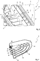
- FIG. 1 comprises an air filter device 1, which is intended for use in a fresh air system of an internal combustion engine, which can preferably be arranged in a motor vehicle, a housing 2, which can be designed, for example, in a shell construction and accordingly have a lower shell 3 and an upper shell, not shown here can.
- a combination 4, which is formed by a filter element 5 and a functional part 6, is inserted into the housing 2.
- a filter body 7 of the filter element 5 separates an in Fig. 1 located below the filter body 7 raw space 8 of an in Fig. 1
- the clean room 9 located above the filter body 7.
- a clean air path 10 leads from the clean room 9 through the functional part 6 to a functional room 11 of the housing 2, which is shown in FIG Fig.
- the functional space 11 leads to a clean air outlet 12, while the raw space 8 is fluidically connected to a raw air inlet 13.
- the clean air outlet 12 and the unfiltered air inlet 13 are each formed on the lower shell 3.
- the functional part 6 is designed to deflect a clean air flow that follows the clean air path 10 and is accordingly deflected from the clean room 9 into the functional room 11 or in the direction of the clean air outlet 12. Downstream of the clean air outlet 12, for example, a sensor for air mass measurement or for air volume flow measurement can be arranged. It is also conceivable to arrange such a sensor in the functional space 11.
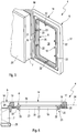
- the filter element 5 comprises the filter body 7 made of a filter material, a sealing frame 14 and a Support frame 15.
- the sealing frame 14 consists of a sealing material and has a filter section 16 and a functional section 17.
- the filter section 16 forms a closed, circumferential border for the filter body 7.
- the functional section 17, on the other hand, forms a closed circumferential border for the support frame 15 is hermetically sealed with respect to the surroundings of the housing 2. Furthermore, the sealing frame 14 in the housing 2 seals the raw space 8 with respect to the clean room 9.
- the support frame 15 forms a closed circumferential border for a functional part opening 18 and is used to fasten the functional part 6 to the filter element 5.
- the functional part opening 18 is completely open or free and is available with its entire opening cross-section to accommodate the respective functional part 6. Accordingly, the functional part opening 18 is defined exclusively by its delimitation by the support frame 15 in the preferred case.
- the support frame 15 also preferably has no additional function in addition to the two functions mentioned, according to which on the one hand it forms the border of the functional part opening 18 and on the other hand serves to fasten the respective functional part 6.
- the filter body 7 is preferably made from a pleated, sheet-like filter material.
- the sealing frame 14 is preferably made from a foamed sealing material.
- the support frame 15 is preferably injection molded from plastic. In principle, the support frame 15 can also be a metal component, preferably a shaped sheet metal part.
- the sealing frame 14 here has a frame section 19 which is jointly assigned to the filter section 16 and the functional section 17. Accordingly this frame section 19 extends along the filter body 7 and along the support frame 15. In the examples shown here, the frame section 19 is designed as a straight web.
- the sealing frame 14 with its filter section 16, its functional section 17 and the frame section 19 is expediently foamed in one piece onto the filter body 7 and onto the support frame 15.
- the sealing frame 14 is expediently foamed onto the support frame 15 in such a way that an in Fig. 6 recognizable outer edge 20 of the support frame 15 is embedded in the sealing material of the sealing frame 14.
- the outer edge 20 is expediently configured so that it runs all the way round, so that the support frame 15 is enclosed in an airtight manner by the functional section 17.
- the support frame 15 can have openings and / or undercut contours, not shown, which enable the outer edge 20 to be embedded in the sealing frame 14 in a form-fitting manner.
- Latching means 21 are preferably formed on the support frame 15, which interact with counter-latching means 22 to form a latching 23.
- the counter-latching means 22 are designed to be complementary to the latching means 21 of the support frame 15 and are located on the functional part 6.
- the latching 23 is formed here by latching hooks and a matching latching contour. In the examples shown here, the latching means 21 of the support frame 15 define such a latching contour, while the counter-latching means 22 of the functional part 6 are designed as latching hooks.
- the sealing frame 14 extends in a sealing plane 24.
- the filter section 16 and the functional section 17 lie next to one another and also extend in the sealing plane 24.
- the filter body 7 is therefore preferably a plate filter element with pleated filter material designed.
- a prefilter body 25 is arranged on an upstream side of the filter body 7, which in the installed state faces the raw space 8, which, for example, can be glued or welded to the filter body 7.
- uniform filter elements 5 of this type and several different functional parts 6 can now be stocked, the different functional parts 6 each being adapted so that they can each be fastened to the support frame 15 of the respective filter element 5.
- the support frame 15 thus defines a mechanical interface which makes it possible to mechanically connect the different functional parts 6 to the respective filter element 5.
- the functional part 6 can have a functional support support frame 26 which is shaped complementarily to the support frame 15 and which, in the assembled state, is in closed circumferential contact with the support frame 15 on the edge side.
- a predetermined positioning of the functional part 6 on the support frame 15 can be implemented in a particularly simple manner.
- an adequate seal between the functional part 6 and the support frame 15 can be achieved.
- the function carrier 6 is not shown in full.
- the function carrier 6 is shown here only in the area of its function carrier support frame 26 on which the counter-locking means 22 are formed.
- the function carrier 6 can have further components which are then expediently enclosed by the function carrier frame 26 and in particular can be formed thereon.
- the function carrier 6 can have a lattice structure (not shown here) that is one from the function carrier frame 26 fills the edged opening and which can be formed integrally on the function carrier frame 26.
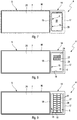
- the respective functional part 6 can form at least one flow-through area 27 and at least one non-flow-through area 28 within the functional part opening 18.
- Different examples are shown here, which illustrate how with the aid of the respective functional part 6, different sized flow-through areas 27 or different sized non-flowable areas 28 can be realized by using different functional parts 6.
- the functional part 6 can have at least one guide vane 29.
- the functional part 6 preferably has a plurality of guide vanes 29.
- the guide vanes 29 serve to deflect the flow and can accordingly be designed to be curved.
- the functional part 6 has a support wall 30, on which at least one guide vane 29 is arranged on each of two sides facing away from one another.
- the support wall 30 can also have a flow guiding function and a flow deflecting function. How the Figures 1 and 2 can be seen, the supporting wall 30 protrudes over the sealing plane 24 in such a way that it protrudes into the clean room 29. In this area it is also expediently curved. In this way, the flow deflection from the clean room 9 into the functional room 11 can be improved.
- the counter-latching elements 22, that is to say in particular the latching hooks, are formed on the guide vanes 29.
- each guide vane 29 has such a counter-locking element 22, preferably in the form of a locking lug or a locking hook.
- these counter-locking elements 22 lock with the respective locking element 21 of the support frame 15.
- the respective latching element 21 of the support frame 15 is formed by a circumferential inner edge 31 of the support frame 15.
- the respective latching means 21 is formed by a collar 32 that extends around the inner edge 31, preferably perpendicularly, protruding.
- the inner edge 31 is braced between the individual latching hooks 22 and a shoulder 37 of the respective guide vane 29.
- the collar 32 is clamped between the latching hook 22 and the functional subframe 26.
- the supporting wall 30 of the functional part 6 in the installed state of the combination 4 can also be used to support and position the functional part 6 on the housing 2, here on the lower shell 3.
- a tongue and groove guide 33 can be implemented, for example, which enables positive engagement between the support wall 30 and the housing 2 or the lower shell 3.
- an outer contour 34 of the supporting wall 30 facing the lower shell 3 can be designed to be supported on the lower shell 3.
- convex contact contours 35 can be formed on this outer contour 34, which enable point-like, in particular pretensioned, contact with the lower shell 3.
- a grip element 36 is indicated, which simplifies the handling of the functional part 6. ****
Landscapes
- Chemical & Material Sciences (AREA)
- Chemical Kinetics & Catalysis (AREA)
- Filtering Of Dispersed Particles In Gases (AREA)
Claims (16)
- Élément de filtre pour un dispositif de filtration d'air (1) d'une installation d'air frais d'un moteur à combustion d'air, en particulier d'un véhicule automobile,- avec un corps de filtre (7) réalisé à partir d'un matériau filtrant,- avec un cadre d'étanchéité (14) réalisé à partir d'un matériau d'étanchéité, qui présente une section de filtre associée au corps de filtre (7), qui entoure le corps de filtre (7) circonférentiellement de manière fermée sur les bords,
caractérisé par- un cadre de support (15) pour fixer une partie fonctionnelle (6),- dans lequel le cadre de support (15) présente et entoure circonférentiellement de manière fermée une ouverture de la partie fonctionnelle (18),- dans lequel le cadre d'étanchéité (14) présente une section fonctionnelle (17) associée au cadre de support (15), qui entoure le cadre de support (15) circonférentiellement de manière fermée sur les bords,- dans lequel des moyens d'encliquetage (21) sont réalisés au niveau du cadre de support (15), lesquels interagissent pour fixer la partie fonctionnelle (6) au niveau du cadre de support (15) avec des contre-moyens d'encliquetage (22) complémentaires à ceux-ci, qui sont réalisés au niveau de la partie fonctionnelle (6),- dans lequel le cadre de support (15) concernant le cadre d'étanchéité (14) et la partie fonctionnelle (6) est un composant distinct. - Élément de filtre selon la revendication 1,
caractérisé en ce que
l'ouverture de partie fonctionnelle (18) est complètement ouverte. - Élément de filtre selon la revendication 1 ou 2,
caractérisé en ce que
le cadre de support (15) constitue uniquement une enceinte fermée circonférentiellement autour de l'ouverture de partie fonctionnelle (18) et est prévu pour fixer la partie fonctionnelle (6) respective, qui, concernant le cadre de support (15), est un composant distinct. - Élément de filtre selon l'une quelconque des revendications 1 à 3,
caractérisé en ce que
le cadre d'étanchéité (14) présente une section de cadre (19), qui est associée conjointement à la section de filtre (16) et à la section fonctionnelle (17) et qui s'étend le long du corps de filtre (7) et le long du cadre de support (15). - Élément de filtre selon l'une quelconque des revendications 1 à 4,
caractérisé en ce que- le cadre d'étanchéité (14) est moulé par moussage sur le corps de filtre (7) et sur le cadre de support (15), et/ou- dans lequel le cadre d'étanchéité (14) est fabriqué à partir d'un matériau d'étanchéité moussé et le cadre de support (15) est fabriqué à partir d'une matière plastique moulée par injection et à partir de métal. - Élément de filtre selon l'une quelconque des revendications 1 à 5,
caractérisé en ce que
le cadre de support (15) est incorporé dans le matériau d'étanchéité du cadre d'étanchéité (14). - Élément de filtre selon l'une quelconque des revendications 1 à 6,
caractérisé en ce que
la cadre d'étanchéité (14) s'étend dans un plan d'étanchéité (24), dans lequel la section de filtre (16) et la section fonctionnelle (17) sont disposées côte à côte. - Élément de filtre selon l'une quelconque des revendications 1 à 7,
caractérisé en ce que
le corps de filtre (7) est agencé comme élément de filtre à plaques, dont le matériau filtrant est plissé. - Combinaison à partir d'un élément de filtre (5) selon l'une quelconque des revendications 1 à 8 et une partie fonctionnelle (6), qui est fixée au niveau du cadre de support (15) de l'élément de filtre (5).
- Combinaison selon la revendication 9,
caractérisée en ce que
la partie fonctionnelle (6) présente un cadre de partie fonctionnelle (26) formé de manière complémentaire au cadre de support (15), dans laquelle le cadre de support (15) à l'état monté est en contact circonférentiellement de manière fermée sur les bords avec le cadre de partie fonctionnelle (26). - Combinaison selon la revendication 9 ou 10,
caractérisé en ce que
la partie fonctionnelle (6) réalise dans l'ouverture de partie fonctionnelle (18) au moins une zone pouvant être traversée (27) et au moins une zone ne pouvant pas être traversée (28). - Combinaison selon l'une quelconque des revendications 9 à 11,
caractérisée en ce que
la partie fonctionnelle (6) présente au moins une aube directrice (29) pour la direction d'écoulement. - Combinaison selon l'une quelconque des revendications 9 à 12,
caractérisée en ce que
la partie fonctionnelle (6) présente une paroi portante (30), au moins une aube directrice (29) est disposée respectivement sur les deux côtés opposés l'un à l'autre. - Combinaison selon la revendication 12 ou 13,
caractérisée en ce qu'
au moins une telle aube directrice (29) présente un contre-élément d'encliquetage (22), qui interagit pour fixer la partie fonctionnelle (6) au niveau du cadre de support (15) avec un moyen d'encliquetage (21) réalisé au niveau du cadre de support (15). - Dispositif de filtration d'air pour une installation d'air frais d'un moteur à combustion d'air, en particulier d'un véhicule automobile,- avec un boîtier (2), dans lequel une combinaison (4) selon l'une quelconque des revendications 9 à 14 est reçue,- dans lequel le corps de filtre (7) dans le boîtier (2) sépare un espace non purifié (8) d'un espace purifié (9),- dans lequel un chemin d'air pur (10) mène de l'espace purifié (9) à travers la partie fonctionnelle (6) vers un espace fonctionnel (11) du boîtier (2) et/ou vers une sortie d'air pur (12) du boîtier (2),- dans lequel la partie fonctionnelle (6) est agencée pour dévier un chemin d'air pur (10) de l'écoulement d'air pur suivant de l'espace purifié (9) vers l'espace fonctionnel (11) et/ou vers la sortie d'air pur (12).
- Système modulaire avec un élément de filtre (5) et au moins deux parties fonctionnelles différentes (6), qui peuvent être fixées sélectivement au niveau du cadre de support (15) de l'élément de filtre (5) et qui se distinguent l'une de l'autre par des géométries et/ou des fonctions différentes, dans lequel l'élément de filtre (5) est équipé :- d'un corps de filtre (7) réalisé à partir d'un matériau filtrant,- d'un cadre d'étanchéité (14) réalisé à partir d'un matériau d'étanchéité, qui présente une section de filtre (16) associée au corps de filtre (7), qui entoure le corps de filtre (7) circonférentiellement de manière fermée sur les bords,- d'un cadre de support (15) pour fixer une partie fonctionnelle (6),- dans lequel le cadre de support (15) présente et entoure circonférentiellement de manière fermée une ouverture de partie fonctionnelle (18),- dans lequel le cadre d'étanchéité (14) présente une section fonctionnelle (17) associée au cadre de support (15), qui entoure le cadre de support (15) circonférentiellement de manière fermée sur les bords,- dans lequel des moyens d'encliquetage (21) sont réalisés au niveau du cadre de support (15), qui interagissent pour fixer la partie fonctionnelle (6) au niveau du cadre de support (15) avec des contre-moyens d'encliquetage (22) complémentaires, qui sont réalisés au niveau de la partie fonctionnelle (6),- dans lequel le cadre de support (15), concernant le cadre d'étanchéité (14) et la partie fonctionnelle (6), est un composant distinct,de sorte qu'une combinaison (4) selon l'une quelconque des revendications 9 à 14 peut être fabriquée avec le système modulaire.
Applications Claiming Priority (2)
| Application Number | Priority Date | Filing Date | Title |
|---|---|---|---|
| DE102013207250.3A DE102013207250A1 (de) | 2013-04-22 | 2013-04-22 | Luftfiltereinrichtung |
| PCT/EP2014/057428 WO2014173708A1 (fr) | 2013-04-22 | 2014-04-11 | Dispositif de filtre à air |
Publications (2)
| Publication Number | Publication Date |
|---|---|
| EP2988848A1 EP2988848A1 (fr) | 2016-03-02 |
| EP2988848B1 true EP2988848B1 (fr) | 2021-09-01 |
Family
ID=50478413
Family Applications (1)
| Application Number | Title | Priority Date | Filing Date |
|---|---|---|---|
| EP14716603.7A Not-in-force EP2988848B1 (fr) | 2013-04-22 | 2014-04-11 | Dispositif de filtre à air |
Country Status (4)
| Country | Link |
|---|---|
| EP (1) | EP2988848B1 (fr) |
| CN (1) | CN105142753B (fr) |
| DE (1) | DE102013207250A1 (fr) |
| WO (1) | WO2014173708A1 (fr) |
Families Citing this family (2)
| Publication number | Priority date | Publication date | Assignee | Title |
|---|---|---|---|---|
| ITUB201543363U1 (it) | 2015-06-03 | 2016-12-03 | Officine Metallurgiche G Cornaglia S P A | Cartuccia filtro aria a pannello compatta ad elevata efficienza per motori endotermici. |
| DE102017006074A1 (de) * | 2017-06-28 | 2019-01-03 | Mann+Hummel Gmbh | Flachfilterelement, insbesondere zur Gasfiltration |
Family Cites Families (15)
| Publication number | Priority date | Publication date | Assignee | Title |
|---|---|---|---|---|
| DE4131716A1 (de) * | 1991-09-24 | 1993-03-25 | Knecht Filterwerke Gmbh | Ansaugluftfilter fuer insbesondere kraftfahrzeuge |
| JP2002061543A (ja) * | 2000-08-22 | 2002-02-28 | Toyo Roki Mfg Co Ltd | エアクリーナ装置 |
| US6752846B2 (en) * | 2002-07-18 | 2004-06-22 | Kohler Co. | Panel type air filter element with integral baffle |
| JP4254349B2 (ja) * | 2003-05-28 | 2009-04-15 | スズキ株式会社 | 内燃機関の吸気装置 |
| KR20050060564A (ko) * | 2003-12-16 | 2005-06-22 | 삼성전자주식회사 | 공기청정기 |
| DE102005004287B4 (de) * | 2005-01-28 | 2013-06-13 | Mann + Hummel Gmbh | Ölfiltereinheit |
| DE202006010888U1 (de) * | 2006-07-13 | 2006-09-28 | Pfannenberg Gmbh | Luftdurchtrittsvorrichtung |
| DE102006039952B4 (de) * | 2006-08-25 | 2012-12-20 | Mahle International Gmbh | Luftfilter |
| FR2922269B1 (fr) * | 2007-10-16 | 2014-01-10 | Mark Iv Systemes Moteurs Sa | Dispositif de filtre a air et vehicule comprenant un tel dispositif. |
| JP5376424B2 (ja) * | 2007-11-28 | 2013-12-25 | 株式会社クボタ | 浸漬型膜分離装置 |
| JP2009203899A (ja) * | 2008-02-28 | 2009-09-10 | Toyota Boshoku Corp | フィルタエレメント及びエアクリーナ |
| DE202009006925U1 (de) * | 2009-05-13 | 2010-09-23 | Mann+Hummel Gmbh | Luftfilter eines Verbrennungsmotors und Zwischenrahmen dafür |
| US8241382B2 (en) * | 2009-07-31 | 2012-08-14 | Ford Global Technologies, Llc | Air cleaner for motor vehicles operating in extreme weather conditions |
| DE102010045985A1 (de) * | 2010-08-05 | 2012-02-09 | Daimler Ag | Luftzuführung einer Brennkraftmaschine mit Luftleitelement |
| JP2012097643A (ja) * | 2010-11-01 | 2012-05-24 | Suzuki Motor Corp | 内燃機関のエアクリーナ構造 |
-
2013
- 2013-04-22 DE DE102013207250.3A patent/DE102013207250A1/de not_active Withdrawn
-
2014
- 2014-04-11 WO PCT/EP2014/057428 patent/WO2014173708A1/fr not_active Ceased
- 2014-04-11 EP EP14716603.7A patent/EP2988848B1/fr not_active Not-in-force
- 2014-04-11 CN CN201480022920.1A patent/CN105142753B/zh not_active Expired - Fee Related
Also Published As
| Publication number | Publication date |
|---|---|
| CN105142753B (zh) | 2017-05-10 |
| DE102013207250A1 (de) | 2014-10-23 |
| CN105142753A (zh) | 2015-12-09 |
| EP2988848A1 (fr) | 2016-03-02 |
| WO2014173708A1 (fr) | 2014-10-30 |
Similar Documents
| Publication | Publication Date | Title |
|---|---|---|
| EP2774667B1 (fr) | Filtres, élément de filtre et boîtier de filtre | |
| EP2509699B1 (fr) | Elément filtrant et filtre à air | |
| EP2731698B1 (fr) | Elément filtrant et dispositif filtrant | |
| EP2463009B2 (fr) | Ensemble filtre | |
| DE202008017059U1 (de) | Filtereinrichtung für Brennkraftmaschinen | |
| DE112015005692T5 (de) | Luftfilter zur Vorreinigung | |
| DE102015011339B4 (de) | Filterelement mit einer umlaufenden Dichtung und Verfahren zu seiner Herstellung | |
| DE102016204776A1 (de) | Außenlufteinleitungsvorrichtung | |
| DE20109702U1 (de) | Luftfiltersystem | |
| DE8429994U1 (de) | Schieberventil mit unterdruck-stellmotor | |
| WO2015055575A1 (fr) | Dispositif de filtration, en particulier pour la filtration de gaz | |
| EP3446768B1 (fr) | Filtre intérieur et dispositif filtrant | |
| EP2692559B1 (fr) | Dispositif de filtre à air avec élément filtrant | |
| DE102004002293A1 (de) | Luftfilter | |
| EP2988848B1 (fr) | Dispositif de filtre à air | |
| DE112009000551T5 (de) | Abgasstrang mit einer Reagenz-Einspritzeinrichtung | |
| WO2016087283A1 (fr) | Elément filtrant en forme de plaque et dispositif filtrant | |
| DE102014219403A1 (de) | Filterelement zum Filtern von Fluid mit einem gefalteten Filtermaterial | |
| DE102020130138A1 (de) | Rundfilterelement, insbesondere zur Gasfiltration | |
| DE102013004284B4 (de) | Filtereinrichtung und Filterelement für eine Filtereinrichtung | |
| DE102017000111A1 (de) | Filterelement mit Zusatzbauteil und Filtersystem | |
| DE3527357C2 (fr) | ||
| EP2592394B1 (fr) | Composant d'un système d'air pour un moteur à combustion interne avec un capteur de paramètre d'air et utilisation du capteur. | |
| DE202005011733U1 (de) | Filterelement | |
| DE102016005555A1 (de) | Flachfilterelement, insbesondere für einen Luftfilter |
Legal Events
| Date | Code | Title | Description |
|---|---|---|---|
| PUAI | Public reference made under article 153(3) epc to a published international application that has entered the european phase |
Free format text: ORIGINAL CODE: 0009012 |
|
| 17P | Request for examination filed |
Effective date: 20150915 |
|
| AK | Designated contracting states |
Kind code of ref document: A1 Designated state(s): AL AT BE BG CH CY CZ DE DK EE ES FI FR GB GR HR HU IE IS IT LI LT LU LV MC MK MT NL NO PL PT RO RS SE SI SK SM TR |
|
| AX | Request for extension of the european patent |
Extension state: BA ME |
|
| DAX | Request for extension of the european patent (deleted) | ||
| STAA | Information on the status of an ep patent application or granted ep patent |
Free format text: STATUS: EXAMINATION IS IN PROGRESS |
|
| 17Q | First examination report despatched |
Effective date: 20170102 |
|
| GRAP | Despatch of communication of intention to grant a patent |
Free format text: ORIGINAL CODE: EPIDOSNIGR1 |
|
| STAA | Information on the status of an ep patent application or granted ep patent |
Free format text: STATUS: GRANT OF PATENT IS INTENDED |
|
| INTG | Intention to grant announced |
Effective date: 20210409 |
|
| RIN1 | Information on inventor provided before grant (corrected) |
Inventor name: SUTSCHITSCH, HANNES Inventor name: RUFFET, VALENTIN Inventor name: VON MERKATZ, HENDRIK Inventor name: TRAVNIK, PETER |
|
| GRAS | Grant fee paid |
Free format text: ORIGINAL CODE: EPIDOSNIGR3 |
|
| GRAA | (expected) grant |
Free format text: ORIGINAL CODE: 0009210 |
|
| STAA | Information on the status of an ep patent application or granted ep patent |
Free format text: STATUS: THE PATENT HAS BEEN GRANTED |
|
| AK | Designated contracting states |
Kind code of ref document: B1 Designated state(s): AL AT BE BG CH CY CZ DE DK EE ES FI FR GB GR HR HU IE IS IT LI LT LU LV MC MK MT NL NO PL PT RO RS SE SI SK SM TR |
|
| REG | Reference to a national code |
Ref country code: GB Ref legal event code: FG4D Free format text: NOT ENGLISH |
|
| REG | Reference to a national code |
Ref country code: CH Ref legal event code: EP Ref country code: AT Ref legal event code: REF Ref document number: 1425600 Country of ref document: AT Kind code of ref document: T Effective date: 20210915 |
|
| REG | Reference to a national code |
Ref country code: DE Ref legal event code: R096 Ref document number: 502014015843 Country of ref document: DE |
|
| REG | Reference to a national code |
Ref country code: IE Ref legal event code: FG4D Free format text: LANGUAGE OF EP DOCUMENT: GERMAN |
|
| REG | Reference to a national code |
Ref country code: LT Ref legal event code: MG9D |
|
| REG | Reference to a national code |
Ref country code: NL Ref legal event code: MP Effective date: 20210901 |
|
| PG25 | Lapsed in a contracting state [announced via postgrant information from national office to epo] |
Ref country code: NO Free format text: LAPSE BECAUSE OF FAILURE TO SUBMIT A TRANSLATION OF THE DESCRIPTION OR TO PAY THE FEE WITHIN THE PRESCRIBED TIME-LIMIT Effective date: 20211201 Ref country code: ES Free format text: LAPSE BECAUSE OF FAILURE TO SUBMIT A TRANSLATION OF THE DESCRIPTION OR TO PAY THE FEE WITHIN THE PRESCRIBED TIME-LIMIT Effective date: 20210901 Ref country code: FI Free format text: LAPSE BECAUSE OF FAILURE TO SUBMIT A TRANSLATION OF THE DESCRIPTION OR TO PAY THE FEE WITHIN THE PRESCRIBED TIME-LIMIT Effective date: 20210901 Ref country code: LT Free format text: LAPSE BECAUSE OF FAILURE TO SUBMIT A TRANSLATION OF THE DESCRIPTION OR TO PAY THE FEE WITHIN THE PRESCRIBED TIME-LIMIT Effective date: 20210901 Ref country code: BG Free format text: LAPSE BECAUSE OF FAILURE TO SUBMIT A TRANSLATION OF THE DESCRIPTION OR TO PAY THE FEE WITHIN THE PRESCRIBED TIME-LIMIT Effective date: 20211201 Ref country code: RS Free format text: LAPSE BECAUSE OF FAILURE TO SUBMIT A TRANSLATION OF THE DESCRIPTION OR TO PAY THE FEE WITHIN THE PRESCRIBED TIME-LIMIT Effective date: 20210901 Ref country code: SE Free format text: LAPSE BECAUSE OF FAILURE TO SUBMIT A TRANSLATION OF THE DESCRIPTION OR TO PAY THE FEE WITHIN THE PRESCRIBED TIME-LIMIT Effective date: 20210901 Ref country code: HR Free format text: LAPSE BECAUSE OF FAILURE TO SUBMIT A TRANSLATION OF THE DESCRIPTION OR TO PAY THE FEE WITHIN THE PRESCRIBED TIME-LIMIT Effective date: 20210901 |
|
| PG25 | Lapsed in a contracting state [announced via postgrant information from national office to epo] |
Ref country code: PL Free format text: LAPSE BECAUSE OF FAILURE TO SUBMIT A TRANSLATION OF THE DESCRIPTION OR TO PAY THE FEE WITHIN THE PRESCRIBED TIME-LIMIT Effective date: 20210901 Ref country code: LV Free format text: LAPSE BECAUSE OF FAILURE TO SUBMIT A TRANSLATION OF THE DESCRIPTION OR TO PAY THE FEE WITHIN THE PRESCRIBED TIME-LIMIT Effective date: 20210901 Ref country code: GR Free format text: LAPSE BECAUSE OF FAILURE TO SUBMIT A TRANSLATION OF THE DESCRIPTION OR TO PAY THE FEE WITHIN THE PRESCRIBED TIME-LIMIT Effective date: 20211202 |
|
| PG25 | Lapsed in a contracting state [announced via postgrant information from national office to epo] |
Ref country code: IS Free format text: LAPSE BECAUSE OF FAILURE TO SUBMIT A TRANSLATION OF THE DESCRIPTION OR TO PAY THE FEE WITHIN THE PRESCRIBED TIME-LIMIT Effective date: 20220101 Ref country code: SM Free format text: LAPSE BECAUSE OF FAILURE TO SUBMIT A TRANSLATION OF THE DESCRIPTION OR TO PAY THE FEE WITHIN THE PRESCRIBED TIME-LIMIT Effective date: 20210901 Ref country code: SK Free format text: LAPSE BECAUSE OF FAILURE TO SUBMIT A TRANSLATION OF THE DESCRIPTION OR TO PAY THE FEE WITHIN THE PRESCRIBED TIME-LIMIT Effective date: 20210901 Ref country code: RO Free format text: LAPSE BECAUSE OF FAILURE TO SUBMIT A TRANSLATION OF THE DESCRIPTION OR TO PAY THE FEE WITHIN THE PRESCRIBED TIME-LIMIT Effective date: 20210901 Ref country code: PT Free format text: LAPSE BECAUSE OF FAILURE TO SUBMIT A TRANSLATION OF THE DESCRIPTION OR TO PAY THE FEE WITHIN THE PRESCRIBED TIME-LIMIT Effective date: 20220103 Ref country code: NL Free format text: LAPSE BECAUSE OF FAILURE TO SUBMIT A TRANSLATION OF THE DESCRIPTION OR TO PAY THE FEE WITHIN THE PRESCRIBED TIME-LIMIT Effective date: 20210901 Ref country code: EE Free format text: LAPSE BECAUSE OF FAILURE TO SUBMIT A TRANSLATION OF THE DESCRIPTION OR TO PAY THE FEE WITHIN THE PRESCRIBED TIME-LIMIT Effective date: 20210901 Ref country code: CZ Free format text: LAPSE BECAUSE OF FAILURE TO SUBMIT A TRANSLATION OF THE DESCRIPTION OR TO PAY THE FEE WITHIN THE PRESCRIBED TIME-LIMIT Effective date: 20210901 Ref country code: AL Free format text: LAPSE BECAUSE OF FAILURE TO SUBMIT A TRANSLATION OF THE DESCRIPTION OR TO PAY THE FEE WITHIN THE PRESCRIBED TIME-LIMIT Effective date: 20210901 |
|
| REG | Reference to a national code |
Ref country code: DE Ref legal event code: R097 Ref document number: 502014015843 Country of ref document: DE |
|
| PLBE | No opposition filed within time limit |
Free format text: ORIGINAL CODE: 0009261 |
|
| STAA | Information on the status of an ep patent application or granted ep patent |
Free format text: STATUS: NO OPPOSITION FILED WITHIN TIME LIMIT |
|
| PG25 | Lapsed in a contracting state [announced via postgrant information from national office to epo] |
Ref country code: IT Free format text: LAPSE BECAUSE OF FAILURE TO SUBMIT A TRANSLATION OF THE DESCRIPTION OR TO PAY THE FEE WITHIN THE PRESCRIBED TIME-LIMIT Effective date: 20210901 Ref country code: DK Free format text: LAPSE BECAUSE OF FAILURE TO SUBMIT A TRANSLATION OF THE DESCRIPTION OR TO PAY THE FEE WITHIN THE PRESCRIBED TIME-LIMIT Effective date: 20210901 |
|
| PGFP | Annual fee paid to national office [announced via postgrant information from national office to epo] |
Ref country code: FR Payment date: 20220427 Year of fee payment: 9 |
|
| 26N | No opposition filed |
Effective date: 20220602 |
|
| PG25 | Lapsed in a contracting state [announced via postgrant information from national office to epo] |
Ref country code: SI Free format text: LAPSE BECAUSE OF FAILURE TO SUBMIT A TRANSLATION OF THE DESCRIPTION OR TO PAY THE FEE WITHIN THE PRESCRIBED TIME-LIMIT Effective date: 20210901 |
|
| REG | Reference to a national code |
Ref country code: CH Ref legal event code: PL |
|
| GBPC | Gb: european patent ceased through non-payment of renewal fee |
Effective date: 20220411 |
|
| REG | Reference to a national code |
Ref country code: BE Ref legal event code: MM Effective date: 20220430 |
|
| PG25 | Lapsed in a contracting state [announced via postgrant information from national office to epo] |
Ref country code: MC Free format text: LAPSE BECAUSE OF FAILURE TO SUBMIT A TRANSLATION OF THE DESCRIPTION OR TO PAY THE FEE WITHIN THE PRESCRIBED TIME-LIMIT Effective date: 20210901 Ref country code: LU Free format text: LAPSE BECAUSE OF NON-PAYMENT OF DUE FEES Effective date: 20220411 Ref country code: LI Free format text: LAPSE BECAUSE OF NON-PAYMENT OF DUE FEES Effective date: 20220430 Ref country code: GB Free format text: LAPSE BECAUSE OF NON-PAYMENT OF DUE FEES Effective date: 20220411 Ref country code: CH Free format text: LAPSE BECAUSE OF NON-PAYMENT OF DUE FEES Effective date: 20220430 |
|
| PG25 | Lapsed in a contracting state [announced via postgrant information from national office to epo] |
Ref country code: BE Free format text: LAPSE BECAUSE OF NON-PAYMENT OF DUE FEES Effective date: 20220430 |
|
| PG25 | Lapsed in a contracting state [announced via postgrant information from national office to epo] |
Ref country code: IE Free format text: LAPSE BECAUSE OF NON-PAYMENT OF DUE FEES Effective date: 20220411 |
|
| REG | Reference to a national code |
Ref country code: AT Ref legal event code: MM01 Ref document number: 1425600 Country of ref document: AT Kind code of ref document: T Effective date: 20220411 |
|
| PG25 | Lapsed in a contracting state [announced via postgrant information from national office to epo] |
Ref country code: AT Free format text: LAPSE BECAUSE OF NON-PAYMENT OF DUE FEES Effective date: 20220411 |
|
| PG25 | Lapsed in a contracting state [announced via postgrant information from national office to epo] |
Ref country code: FR Free format text: LAPSE BECAUSE OF NON-PAYMENT OF DUE FEES Effective date: 20230430 |
|
| PG25 | Lapsed in a contracting state [announced via postgrant information from national office to epo] |
Ref country code: HU Free format text: LAPSE BECAUSE OF FAILURE TO SUBMIT A TRANSLATION OF THE DESCRIPTION OR TO PAY THE FEE WITHIN THE PRESCRIBED TIME-LIMIT; INVALID AB INITIO Effective date: 20140411 |
|
| PG25 | Lapsed in a contracting state [announced via postgrant information from national office to epo] |
Ref country code: MK Free format text: LAPSE BECAUSE OF FAILURE TO SUBMIT A TRANSLATION OF THE DESCRIPTION OR TO PAY THE FEE WITHIN THE PRESCRIBED TIME-LIMIT Effective date: 20210901 Ref country code: CY Free format text: LAPSE BECAUSE OF FAILURE TO SUBMIT A TRANSLATION OF THE DESCRIPTION OR TO PAY THE FEE WITHIN THE PRESCRIBED TIME-LIMIT Effective date: 20210901 |
|
| PG25 | Lapsed in a contracting state [announced via postgrant information from national office to epo] |
Ref country code: TR Free format text: LAPSE BECAUSE OF FAILURE TO SUBMIT A TRANSLATION OF THE DESCRIPTION OR TO PAY THE FEE WITHIN THE PRESCRIBED TIME-LIMIT Effective date: 20210901 |
|
| PGFP | Annual fee paid to national office [announced via postgrant information from national office to epo] |
Ref country code: DE Payment date: 20240418 Year of fee payment: 11 |
|
| PG25 | Lapsed in a contracting state [announced via postgrant information from national office to epo] |
Ref country code: MT Free format text: LAPSE BECAUSE OF FAILURE TO SUBMIT A TRANSLATION OF THE DESCRIPTION OR TO PAY THE FEE WITHIN THE PRESCRIBED TIME-LIMIT Effective date: 20210901 |
|
| P01 | Opt-out of the competence of the unified patent court (upc) registered |
Free format text: CASE NUMBER: APP_34601/2024 Effective date: 20240527 |
|
| REG | Reference to a national code |
Ref country code: DE Ref legal event code: R119 Ref document number: 502014015843 Country of ref document: DE |
|
| PG25 | Lapsed in a contracting state [announced via postgrant information from national office to epo] |
Ref country code: DE Free format text: LAPSE BECAUSE OF NON-PAYMENT OF DUE FEES Effective date: 20251104 |