EP2988860B1 - Verfahren und versorgungseinheit zur restabilisierung von radikalisch polymerisierbaren monomeren - Google Patents
Verfahren und versorgungseinheit zur restabilisierung von radikalisch polymerisierbaren monomeren Download PDFInfo
- Publication number
- EP2988860B1 EP2988860B1 EP14719742.0A EP14719742A EP2988860B1 EP 2988860 B1 EP2988860 B1 EP 2988860B1 EP 14719742 A EP14719742 A EP 14719742A EP 2988860 B1 EP2988860 B1 EP 2988860B1
- Authority
- EP
- European Patent Office
- Prior art keywords
- gas
- supply unit
- vessel
- line
- inhibitor solution
- Prior art date
- Legal status (The legal status is an assumption and is not a legal conclusion. Google has not performed a legal analysis and makes no representation as to the accuracy of the status listed.)
- Active
Links
Images

Classifications
-
- C—CHEMISTRY; METALLURGY
- C07—ORGANIC CHEMISTRY
- C07B—GENERAL METHODS OF ORGANIC CHEMISTRY; APPARATUS THEREFOR
- C07B63/00—Purification; Separation; Stabilisation; Use of additives
- C07B63/04—Use of additives
-
- B—PERFORMING OPERATIONS; TRANSPORTING
- B01—PHYSICAL OR CHEMICAL PROCESSES OR APPARATUS IN GENERAL
- B01J—CHEMICAL OR PHYSICAL PROCESSES, e.g. CATALYSIS OR COLLOID CHEMISTRY; THEIR RELEVANT APPARATUS
- B01J19/00—Chemical, physical or physico-chemical processes in general; Their relevant apparatus
- B01J19/0006—Controlling or regulating processes
- B01J19/002—Avoiding undesirable reactions or side-effects, e.g. avoiding explosions, or improving the yield by suppressing side-reactions
-
- B—PERFORMING OPERATIONS; TRANSPORTING
- B01—PHYSICAL OR CHEMICAL PROCESSES OR APPARATUS IN GENERAL
- B01J—CHEMICAL OR PHYSICAL PROCESSES, e.g. CATALYSIS OR COLLOID CHEMISTRY; THEIR RELEVANT APPARATUS
- B01J4/00—Feed or outlet devices; Feed or outlet control devices
- B01J4/001—Feed or outlet devices as such, e.g. feeding tubes
-
- B—PERFORMING OPERATIONS; TRANSPORTING
- B01—PHYSICAL OR CHEMICAL PROCESSES OR APPARATUS IN GENERAL
- B01J—CHEMICAL OR PHYSICAL PROCESSES, e.g. CATALYSIS OR COLLOID CHEMISTRY; THEIR RELEVANT APPARATUS
- B01J2219/00—Chemical, physical or physico-chemical processes in general; Their relevant apparatus
- B01J2219/00049—Controlling or regulating processes
- B01J2219/00245—Avoiding undesirable reactions or side-effects
- B01J2219/00272—Addition of reaction inhibitor
Definitions
- the present invention relates to a process for the stabilization of radically polymerizable monomers and to a supply unit for carrying out the process.
- Monomers which are free radically polymerizable such as (meth) acrylic acid and the derivatives thereof, are handled in the chemical industry in relatively large containers, for example in storage tanks or columns.
- polymerization inhibitors It is known to use for this purpose polymerization inhibitors. It is essential that the polymerization inhibitors are added in the required amount and sufficient mixing with the monomers can be effected.
- a conventional introduction of the polymerization inhibitors and mixing by means of a pump is disadvantageous because the power required for the operation of a pump power supply is not guaranteed in an emergency.
- the WO 99/59717 therefore describes a supply system in which an inhibitor solution using a compressed gas in z. B. a storage tank containing the monomers is introduced. The mixing of monomers and inhibitor solution is carried out by further introduction of inert gas, such as nitrogen.
- inert gas such as nitrogen
- the present invention is therefore based on the object of providing a process for the stabilization of radically polymerizable monomers and an apparatus for carrying out the process which ensures that the inhibitor solution is introduced substantially completely into the monomer container and sufficient mixing of monomer container contents and inhibitor solution can be effected.
- restabilization is meant here the inhibition of an already initiated polymerization of radically polymerizable monomers and stabilization of the remaining monomers against further polymerization.
- stabilization also includes the post-stabilization of monomers without the polymerization has already started as well as the stabilization of monomers, if there is contamination or is to be feared with materials that can trigger or support a polymerization or if a fire has broken out, or the danger of a fire exists.
- container is meant a container of any shape, eg a cylindrical, rectangular, square or spherical tank. Preferably, it is a substantially cylindrical container, in particular a standing cylindrical container.
- the height to diameter ratio of the standing cylindrical container is generally ⁇ 0.1 and preferably in the range of 0.1 to 8, especially 0.1 to 5.
- the tank volume is in particular in the range of 20 to 10,000 m 3 , corresponding to a height of the tank from 3 to 20 m.
- the boiler for the inhibitor solution is expediently an approximately cylindrical container, preferably made of stainless steel.
- the compressed gas storage tank generally has means for reducing the pressure, which regulate the gas outlet at the compressed gas storage tank.
- pressurized gas flows via the gas supply line into the inhibitor solution kettle and pushes the inhibitor solution via the withdrawal line, which extends into the inhibitor solution, advantageously almost to the bottom of the inhibitor solution kettle, into which the monomers containing Container leading pipe.
- This line preferably comprises at least one horizontal and / or sloping, and a rising, in particular substantially vertical, part. It may be advantageous to choose the diameter of the horizontal or sloping part of the line larger than the diameter of the ascending line.
- the line over its entire length has the substantially same diameter.
- the means for introducing the inhibitor solution and the mixed gas is preferably a tube which ends in the region of the bottom of the monomer container.
- a telescopic lance is in the WO 99/24161 to which reference is made in its entirety.
- the flow rate of the compressed gas is adjusted so that the flow regime of the inhibitor solution, a plug flow or ring flow, especially in the rising part of the line results.
- the formation of the plug flow or ring flow depends inter alia on the flow velocity of the compressed gas and the diameter of the pipe.
- the flow rate of the compressed gas is preferably in the range of 6 to 12 m / s, in particular 8 to 12 m / s. The determination of the flow rate is known to the person skilled in the art.
- the introduction of the inhibitor solution is preferably carried out in the region of the bottom of the container (distance from the bottom preferably 1/100 to 1/10 of the container height, in spherical containers at a distance of 1/100 to 1/10 from the wall).
- the introduction can also take place at a greater distance from the floor or the wall.
- the rising part of the supply line extends in particular over a height of 1/10 to 10/10 of the container height.
- the inhibitor solution In order for the inhibitor solution to inhibit on-going polymerization or prevent the onset of polymerization, it must be effectively mixed with the contents of the monomer container. For this purpose, gas is blown in the area of the container bottom. The gas bubbles rising in the monomer liquid in the container cause vertical circulation of the contents of the container, causing mixing (provided the viscosity of the contents of the container is ⁇ 350 mPas, which is the case for the monomer liquids and temperatures in question ). Mixing is particularly effective when the conduit is located near the wall and the gas leaking occurs near the bottom of the vessel. However, the inhibitor solution can only serve its purpose if the mixing is sufficiently rapid and uniform.
- the gas empty tube speed is in the range of 0.1 - 20 mm / s, in particular 0.1 - 10 mm / s.
- means are provided in the gas supply line which connects the compressed gas storage tank with the inhibitor solution tank. These agents are preferably a diaphragm, which is designed, in particular, on the basis of DIN ISO 5167-2.
- the panel includes an opening. The size of the opening is to be selected depending on the diameter of the gas inlet and the size of the container. In addition, this means causes a constant gas mass flow.
- the amount of pressurized gas required to effect the mixing of the inhibitor solution and the contents of the container depends on the size of the container or on the volume of the monomer liquid present in the container. Should a supply unit not be sufficient to maintain the minimum gas empty pipe speed during the time required for mixing, it is advantageous to use either a supply unit with one or more additional compressed gas storage containers or one or more further serially connected supply units. In order to adjust the gas empty tube speed, it may be necessary to use one or more further supply units connected in parallel.
- nitrogen or a mixture of nitrogen and oxygen having a volume ratio of from 5 to 21% by volume, in particular from 5 to 8% by volume, of oxygen is used as the compressed gas.
- the supply unit according to the invention may comprise one or more, preferably 1 to 6, compressed gas storage containers, which optionally have means for reducing the pressure.
- the supply unit is designed as a mobile unit.
- At the end of the extraction line means are provided for connecting the extraction line to the line to the tank.
- the encrustations can be prevented by the mentioned rupture disk.
- a rupture disc preferably a dead space rupture disc
- closed which is destroyed during commissioning of the supply unit.
- Telescopic lance which is located above the liquid level of the container contents when not in use and is protected from monomer vapor and liquid.
- Radically polymerizable monomers are generally vinyl monomers. Examples of these are acrylic acid, methacrylic acid, acrylic esters, methacrylic acid esters, substituted acrylic acid esters and methacrylic acid esters such as hydroxyalkyl acrylates and methacrylates, itaconic acid and derivatives thereof, maleic acid and derivatives thereof, styrene and derivatives thereof, N-vinyl lactams such as N-vinylpyrrolidone etc.
- Suitable inhibitors are, for example, phenothiazine and derivatives thereof, such as N-alkylated phenothiazines, for example N-benzylphenothiazine or N- (1-phenylethyl) phenothiazine, N- (diphenylmethyl) phenothiazine, N, N'-dimethylphenazine, phenoxazine, promazine and the hydrochloride thereof , Carbazole, N-ethylcarbazole, hydroquinones and derivatives thereof, such as hydroquinone ethers, for example hydroquinone monomethyl ether (MeHQ), alkyl-substituted hydroquinones, for example mono-t-butylhydroquinone, 2,5-di-t-butylhydroquinone or toluhydroquinone.
- N-alkylated phenothiazines for example N-benzylphenothiazine or N-
- the inhibitors are used as a solution in an organic solvent.
- Suitable solvents are in particular acetone, ethyl acetate and preferably N-alkylpyrrolidones, such as N-methylpyrrolidone (NMP) and / or N-ethylpyrrolidone.
- NMP N-methylpyrrolidone
- a particularly preferred inhibitor solution is a solution of phenothiazine in NMP.
- the inhibitor content of the solution is at least 10% by weight to 55% by weight. Particular preference is given to a 30-40% strength by weight solution of phenothiazine in NMP, which may optionally contain up to 10% by weight of hydroquinone ether, in particular MEHQ.
- the required amount of inhibitor depends on the size of the tank, whereby the quantity calculation is based on 100% fill level.
- the amount of inhibitor is further dependent on the inhibitor used and the monomers to be stabilized.
- a concentration of about 200 ppm to 300 ppm phenothiazine is in most cases able to inhibit the polymerization of the monomers. It has been found that in most cases concentrations of 50 to 1000 ppm of phenothiazine are sufficient to inhibit the polymerization in such a way that it is no longer hazardous. If the amount of inhibitor solution of a supply unit is insufficient to stabilize the To effect monomers, one uses one or more other serially connected supply units.
- the inventive method and the supply unit according to the invention enable the stabilization of radically polymerizable monomers in a reliable, rapid and economical manner and are independent of energy sources and mixing devices, which is particularly important in emergencies with interruption of the power supply.
- the inhibitor can be quickly introduced into the tank and mixed with the tank contents, thus reliably inhibiting a radical polymerization even in advanced stages.
- the Fig. 1 shows a schematic representation of a connected to a container 1 according to the invention supply unit 11.
- the container is designed as a tank 1.
- the tank 1 has an opening 2 with a vertical connecting flange 3.
- a pipe 4 of a device for introducing the inhibitor solution and the mixed gas into the interior 5 of the tank 1 projects through the opening 2.
- the pipe 4 with the end 6 located near the bottom of the tank 1 serves to feed inhibitor solution and mixed gas.
- the tube 4 is provided at its other end with a support flange 9 for attachment to the flange 3 of the tank 1, wherein the attachment can be made directly or using an intermediate flange.
- a supply line 10 is connected to be introduced into the interior 5 inhibitor solution and the mixed gas.
- the supply line 10 comprises a substantially horizontal part and a in Essentially vertically rising part. Alternatively, the horizontal part may also be formed descending.
- the supply unit 11 is connected to the supply line 10 only in case of danger, for which purpose coupling means 12a and 12b are provided.
- the inhibitor solution is located in the boiler 13 of the supply unit 11, which is connected to two compressed gas storage containers in the form of propellant gas bottles 14. Due to the side view only one of the two LPG bottles 14 can be seen.
- a removal tube which extends with its one end almost to the bottom of the vessel 13, wherein the other end is connected to the hose 15.
- By opening the propellant gas cylinders 14 compressed gas is introduced into the vessel 13 via the compressed gas feeds 17, so that the inhibitor solution is expelled from the boiler 13 via the removal pipe and introduced through the pipe 4 into the tank contents.
- gas is introduced from the propellant gas cylinders 14 via the boiler 13 and the supply line 10 into the tank 1 in such a way that the gas empty pipe speed is ⁇ 0.1 m / s. Due to the rising gas bubbles an upward flow in the interior 5 of the tank 1 is caused, which is illustrated by the arrows 7. This upward flow in the region of the pipe 4 also induces a corresponding flow in adjacent regions, represented by the arrows 8.
- the introduction of the gas causes intensive mixing of the tank contents with the inhibitor solution.
- the end 6 of the tube 4 is arranged in the vicinity of a wall of the tank 1 and in particular in the vicinity of the bottom of the tank 1. Alternatively, the tube 4 can also be guided through the side wall of the tank 1 into the interior 5 of the tank.
- the supply unit 11 is arranged at a distance from the tank 1.
- the distance between the supply unit 11 and the tank 1 should be at least 20 m.
- the maximum distance should be 200 m.
- the coupling means 12a is connected to the extraction pipe via a flexible hose 15, while the coupling means 12b is fixed to the end of the supply pipe 10.
- the boiler 13 is provided with rollers 18, 19 and a handle 20, so that the supply unit 11 can be moved by hand.
- the wheels 18 essentially carry the weight of the supply unit and the wheel 19 is designed as a steering role.
- pressure reducing valves 21 are connected, by means of which the high pressure gas bottles 14 leaving Gas is released to a constant pressure of about 10 bar.
- the boiler 13 has a filling opening, the closure 22 is provided with a safety pressure relief valve. If the supply unit 11 is actuated, a pressure builds up in the pipe 4. As a result, the inhibitor solution is forced through the tube 4 into the tank interior 5.
- the flow rate of the compressed gas is adjusted so that a plug flow or ring flow results in the vertically rising part of the feed line 10 as a flow regime of the inhibitor solution. This ensures that all of the inibitor solution in line 10 is transported to tank 1.
- the flow rate is adjusted to a value between 6 and 12 m / s, in particular to a value between 8 and 12 m / s.
- the amount of inhibitor solution required is based on the size of the tank 1, it is necessary for large tanks 1 to connect more than one supply unit 11 to the tank 1. For this purpose, several supply units 11 can be connected in parallel. Depending on the need for mixed gas, the supply unit 11 may comprise one or more compressed gas storage containers 14.
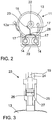
- FIG. 2 the plan view of the erected supply unit is shown.
- the boiler 13 the propellant bottles 14 attached thereto and the handle 20.
- the tube 15 is wound, the end of which is provided with the coupling means 12a.
- the compressed gas feeds 19 of the two propellant gas cylinders 14 are conducted in a three-way connection 28 into a common feed 17.
- the common feed 17 directs the compressed gas from both propellant bottles 14 via a connecting piece 23 in the container.
- FIG. 3 is the fitting 23, which connects the common feed 17 to the boiler 13, shown in detail.
- the connecting piece 23 comprises an upper part 24 and a lower part 25, the lower part 25 enclosing the upper part 24.
- the compressed gas supply 17 terminates in the upper part 24.
- Between the upper 24 and the lower part 25 is a diaphragm 26 with an opening 27.
- the size of the opening 27 is selected according to the diameter of the supply line 10 and the size of the tank 1. This allows you to set the required gas tube velocity. Specifically, by selecting the diameter of the opening, the gas empty tube velocity is set to be ⁇ 0.1 mm / sec. This ensures a sufficiently rapid and uniform mixing of the inhibitor solution with the contents of the tank 1.
Landscapes
- Chemical & Material Sciences (AREA)
- Organic Chemistry (AREA)
- Chemical Kinetics & Catalysis (AREA)
- Polymerisation Methods In General (AREA)
Description
- Die vorliegende Erfindung betrifft ein Verfahren zur Restabilisierung von radikalisch polymerisierbaren Monomeren und eine Versorgungseinheit zur Durchführung des Verfahrens.
- Monomere, die radikalisch polymerisierbar sind, wie (Meth)acrylsäure und die Derivate davon, werden in der chemischen Industrie in relativ großen Behältern gehandhabt, beispielsweise in Lagertanks oder Kolonnen. Dabei besteht die Gefahr, dass durch Temperaturerhöhung, Kühlungsausfall, Stabilisatorinaktivität oder-mangel die Polymerisation der Monomere unerwünschterweise in Gang gesetzt wird. Dadurch kann es zu einer erheblichen Gefährdung der Produktionsanlage kommen, wenn die anspringende Polymerisation nicht rasch und wirksam unterbunden und gestoppt werden kann. Es ist bekannt, zu diesem Zweck Polymerisationsinhibitoren zu verwenden. Wesentlich ist dabei, dass die Polymerisationsinhibitoren in der erforderlichen Menge zugegeben und eine ausreichende Vermischung mit den Monomeren bewirkt werden kann. Eine konventionelle Einbringung der Polymerisationsinhibitoren und Vermischung mit Hilfe einer Pumpe ist nachteilig, weil die für den Betrieb einer Pumpe erforderliche Stromversorgung in einem Notfall nicht gewährleistet ist. Die
WO 99/59717 WO 99/59717 - Der vorliegenden Erfindung liegt daher die Aufgabe zugrunde, ein Verfahren zur Restabilisierung von radikalisch polymerisierbaren Monomeren und eine Vorrichtung zur Durchführung des Verfahrens zur Verfügung zu stellen, das sicherstellt, dass die Inhibitorlösung im Wesentlichen vollständig in den Monomerenbehälter eingebracht und eine ausreichende Vermischung von Monomerenbehälterinhalt und Inhibitorlösung bewirkt werden kann.
- Diese Aufgabe wird gelöst durch ein Verfahren zur Restabilisierung von radikalisch polymerisierbaren Monomeren, umfassend die Schritte
- a) Einbringen einer Lösung eines Inhibitors der radikalischen Polymerisation mit einem inerten Druckgas in einen die Monomere enthaltenden Behälter über wenigstens eine Leitung (Zuführungsleitung), die einen ansteigenden Bereich umfasst und an ihrem Ende Mittel zum Einleiten der Inhibitorlösung und zum Einblasen von Gas in den Behälter aufweist, und
- b) Vermischen des Behälterinhalts und der Inhibitorlösung durch Einblasen von Gas durch die Leitung,
- Die Inhibitorlösung wird in Form einer Versorgungseinheit bereitgestellt, umfassend
- (a) einen Kessel für die Inhibitorlösung mit einem in die Inhibitorlösung reichenden Entnahmerohr,
- (b) wenigstens einen Druckgasspeicherbehälter, der mit dem Kessel für die Inhibitorlösung über eine Gaszuleitung verbunden ist,
- (c) Mittel zur Druckverringerung am Druckgasspeicherbehälter,
- (d) in der Gaszuleitung Mittel zur Einstellung der Gasleerrohrgeschwindigkeit und
- (e) Mittel zum Anschluss der Entnahmeleitung an die Leitung zum Monomerenbehälter.
- Unter "Restabilisierung" ist hier die Inhibierung einer bereits angelaufenen Polymerisation radikalisch polymerisierbarer Monomere und Stabilisierung der verbleibenden Monomere gegen eine weitere Polymerisation zu verstehen. Der Ausdruck "Restabilisierung" umfasst aber auch die Nachstabilisierung von Monomeren ohne dass die Polymerisation bereits angelaufen ist sowie die Stabilisierung von Monomeren, wenn eine Kontamination mit Materialien vorliegt oder zu befürchten ist, welche eine Polymerisation auslösen oder unterstützen können oder wenn ein Feuer ausgebrochen ist oder die Gefahr eines Feuers besteht.
- Unter "Behälter" ist hier ein Behälter jeglicher Form zu verstehen, z.B. ein zylindrischer, rechteckiger, quadratischer oder kugelförmiger Tank. Vorzugsweise handelt es sich um einen im Wesentlichen zylindrischen Behälter, insbesondere einen stehenden zylindrischen Behälter. Das Verhältnis von Höhe zu Durchmesser des stehenden zylindrischen Behälters ist im allgemeinen ≥ 0,1 und liegt vorzugsweise im Bereich von 0,1 bis 8, insbesondere 0,1 bis 5. Das Tankvolumen liegt insbesondere im Bereich von 20 bis 10000 m3, entsprechend einer Höhe des Tanks von 3 bis 20 m.
- Bei dem Kessel für die Inhibitorlösung handelt es sich zweckmässigerweise um einen annähernd zylindrischen Behälter, vorzugsweise aus Edelstahl. Der Druckgasspeicherbehälter weist in der Regel Mittel zur Druckveringerung auf, die den Gasaustritt am Druckgasspeicherbehälter regeln. Durch Öffnen der Mittel zur Druckverringerung strömt Druckgas über die Gaszuleitung in den Kessel für die Inhibitorlösung und drückt die Inhibitorlösung über die Entnahmeleitung, die in die Inhibitorlösung, vorteilhafterweise bis fast zum Boden des Kessels für die Inhibitorlösung, reicht, in die zu dem die Monomere enthaltenden Behälter führende Leitung. Diese Leitung umfasst vorzugsweise mindestens einen horizontalen und/oder abfallenden, und einen ansteigenden, insbesondere im Wesentlichen senkrechten, Teil. Dabei kann es vorteilhaft sein, den Durchmesser des horizontalen bzw. abfallenden Teils der Leitung größer zu wählen als den Durchmesser der aufsteigenden Leitung. Dadurch werden Druckabfall und Einspeisezeit der Inhibitorlösung minimiert, insbesondere wenn die Versorgungseinheit aus Sicherheitsgründen in größerem Abstand (20 - 100 m) von dem MonomerenbehälterTank angeordnet ist. Bevorzugt hat die Leitung über ihre gesamte Länge den im Wesentlichen gleichen Durchmesser.
- Bei den Mitteln zum Einleiten der Inhibitorlösung und des Mischgases handelt es sich bevorzugt um ein Rohr, das im Bereich des Bodens des Monomerenbehälters endet. Zweckmäßigerweise ist das Rohr mit einer Berstscheibe, insbesondere einer totraumfreien Berstscheibe, verschlossen, die bei Inbetriebnahme der Versorgungseinheit zerstört wird.
- Gemäß einer weiteren Ausführungsform der Mittel zum Einleiten der Inhibitorlösung und des Mischgase handelt es sich um eine Teleskoplanze. Eine derartige Teleskoplanze ist in der
WO 99/24161 - Um sicher zu stellen, dass die gesamte in der Leitung befindliche Inhibitorlösung in den Tank transportiert wird, wird die Strömungsgeschwindigkeit des Druckgases so eingestellt, dass sich als Strömungsregime der Inhibitorlösung eine Pfropfenströmung oder Ringströmung, insbesondere im ansteigenden Teil der Leitung, ergibt. Die Ausbildung der Pfropfenströmung oder Ringströmung hängt unter anderem von der Strömungsgeschwindigkeit des Druckgases und dem Leitungsdurchmesser ab. Vorzugsweise liegt die Strömungsgeschwindigkeit des Druckgases im Bereich von 6 - 12 m/s, insbesondere 8 - 12 m/s. Die Ermittlung der Strömungsgeschwindigkeit ist dem Fachmann bekannt.
- Beispielsweise kann sie nach den in Multiphase Science and Technology, Chapter 1, Seiten 1-94, von A. E. Dukler und Y. Taitel beschriebenen Methoden erfolgen.
- Die Einleitung der Inhibitorlösung erfolgt vorzugsweise im Bereich des Bodens des Behälters (Abstand vom Boden bevorzugt 1/100 bis 1/10 der Behälterhöhe; bei kugelförmigen Behältern im Abstand von 1/100 bis 1/10 von der Wand). Die Einleitung kann jedoch auch in größerem Abstand vom Boden bzw. der Wand erfolgen.
- Der ansteigende Teil der Zuleitung erstreckt sich insbesondere über eine Höhe von 1/10 bis 10/10 der Behälterhöhe.
- Damit die Inhibitorlösung eine schon laufende Polymerisation inhibiert oder das Einsetzen einer Polymerisation verhindert, muss sie mit dem Inhalt des Monomerenbehälters wirksam vermischt werden. Zu diesem Zweck wird Gas im Bereich des Behälterbodens eingeblasen. Die in der im Behälter befindlichen Monomerflüssigkeit aufsteigenden Gasblasen bewirken eine vertikale Zirkulation des Behälterinhalts, so dass es zu einer Vermischung kommt (vorausgesetzt, die Viskosität des Behälterinhalts ist < 350 mPas, was bei den hier in Frage kommenden Monomerenflüssigkeiten und Temperaturen im Allgemeinen der Fall ist). Die Vermischung ist besonders effektiv, wenn die Leitung in der Nähe der Wand angeordnet ist und der Gasaustritt im Bereich des Bodens des Behälters erfolgt. Die Inhibitorlösung kann allerdings nur dann ihren Zweck erfüllen, wenn das Vermischen ausreichend rasch und gleichmäßig erfolgt. Es hat sich gezeigt, dass hierzu eine minimale Gasleerrohrgeschwindigkeit im Behälter von ≥ 0,1 mm/s erforderlich ist. Im Allgemeinen liegt die Gasleerrohrgeschwindigkeit im Bereich von 0,1 - 20 mm/s, insbesondere 0,1 - 10 mm/s. Um dies zu erreichen, sind Mittel in der Gaszuleitung vorgesehen, welche den Druckgasspeicherbehälter mit dem Kessel für die Inhibitorlösung verbindet. Bevorzugt handelt es sich bei diesen Mitteln um eine Blende, die insbesondere in Anlehnung an die DIN ISO 5167-2 ausgebildet ist. Die Blende umfasst dabei eine Öffnung. Die Größe der Öffnung ist dabei in Abhängigkeit von dem Durchmesser der Gaszuleitung und der Größe des Behälters auszuwählen. Außerdem wird durch diese Mittel ein konstanter Gasmassenstrom bewirkt.
- Die Gasleerrohrgeschwindigkeit lässt sich nach folgender Formel berechnen:

- Die Menge an Druckgas, die erforderlich ist, um die Vermischung von Inhibitorlösung und Behälterinhalt zu bewirken, hängt von der Größe des Behälters bzw. von dem Volumen der im Behälter befindlichen Monomerenflüssigkeit ab. Sollte eine Versorgungseinheit nicht ausreichen, um während der Zeit, die zum Vermischen erforderlich ist, die minimale Gasleerrohrgeschwindigkeit aufrecht zu erhalten, ist es vorteilhaft, entweder eine Versorgungseinheit mit einem oder mehreren zusätzlichen Druckgasspeicherbehältern oder eine oder mehrere weitere seriell geschaltete Versorgungseinheiten zu verwenden. Um die Gasleerrohrgeschwindigkeit einzustellen, kann es erforderlich sein, ein oder mehrere weitere parallel geschaltete Versorgungseinheiten zu verwenden.
- Als Druckgas verwendet man insbesondere Stickstoff oder ein Gemisch aus Stickstoff und Sauerstoff mit einem Volumenverhältnis von 5 bis 21 Vol.-%, insbesondere 5 bis 8 Vol.-%, Sauerstoff.
- Die erfindungsgemäße Versorgungseinheit kann einen oder mehrere, bevorzugt 1 bis 6, Druckgasspeicherbehälter umfassen, die gegebenenfalls Mittel zur Druckverringerung aufweisen. Besonders bevorzugt ist die Versorgungseinheit als fahrbare Einheit ausgebildet.
- Am Ende der Entnahmeleitung sind Mittel zum Anschluss der Entnahmeleitung an die Leitung zum Tank vorgesehen.
- Bei der in den Behälter reichenden Leitung ist zu berücksichtigen, dass sich in Toträumen etc. oder durch Kondensation von Monomer an kalten Oberflächen inhibitorverarmtes oder inhibitorfreies Monomer bilden kann, das leicht polymerisieren und daher Verkrustungen bilden kann. Die Gefahr der Bildung von Verkrustungen kann verringert oder sogar vermieden werden, indem die Leitung mit einem geringen Strom von Stickstoff oder einem Gemisch aus Stickstoff und Sauerstoff (5-21 Vol.-% Sauerstoff) kontinuierlich gespült wird, wobei der Strom über ein Ventil in die Leitung eingespeist wird. Wenn der Gasdruck einen bestimmten Wert unterschreitet, ist es zweckmäßig ein Alarmsignal auszulösen.
- Alternativ können die Verkrustungen durch die erwähnte Berstscheibe verhindert werden. Dabei wird die in den Tank reichende Leitung an ihrem Ende mit einer Berstscheibe, vorzugsweise eine totraumfreie Berstscheibe, verschlossen, die bei Inbetriebnahme der Versorgungseinheit zerstört wird. Eine weitere Alternative ist der Einsatz der erwähnten Teleskoplanze, die sich bei Nichtverwendung oberhalb des Flüssigkeitsspiegels des Behälterinhalts befindet und vor Monomerendampf und -flüssigkeit geschützt ist.
- Das erfindungsgemäße Verfahren und die erfindungsgemäße Versorgungseinheit sind geeignet, eine effektive Stabilisierung von radikalisch polymerisierbaren Monomeren zu bewirken bzw. eine schon begonnene Polymerisation radikalisch polymerisierbarer Monomere zu inhibieren. Radikalisch polymerisierbare Monomere sind im allgemeinen Vinylmonomere. Beispiele hierfür sind Acrylsäure, Methacrylsäure, Acrylsäureester, Methacrylsäureester, substituierte Acrylsäureester und Methacrylsäureester, wie Hydroxyalkylacrylate und -methacrylate, Itaconsäure und die für Acrylsäure genannten Derivate davon, Maleinsäure und die für Acrylsäure genannten Derivate davon, Styrol und Derivate davon, N-Vinyllactame, wie N-Vinylpyrrolidon etc.
- Geeignete Inhibitoren sind beispielsweise Phenothiazin und Derivate davon, wie N-alkylierte Phenothiazine, beispielsweise N-Benzylphenothiazin oder N-(1-Phenylethyl)phenothiazin, N-(Diphenylmethyl)phenothiazin, N,N'-Dimethylphenazin, Phenoxazin, Promazin und das Hydrochlorid davon, Carbazol, N-Ethylcarbazol, Hydrochinone und Derivate davon, wie Hydrochinonether, beispielsweise Hydrochinonmonomethylether (MeHQ), alkylsubstituierte Hydrochinone, beispielsweise Mono-t-butylhydrochinon, 2,5-Di-t-butylhydrochinon oder Toluhydrochinon.
- Die Inhibitoren kommen als Lösung in einem organischen Lösungsmittel zur Anwendung. Geeignete Lösungsmittel sind insbesondere Aceton, Ethylacetat und bevorzugt N-Alkylpyrrolidone, wie N-Methylpyrrolidon (NMP) und/oder N-Ethylpyrrolidon. Eine besonders bevorzugte Inhibitorlösung ist eine Lösung von Phenothiazin in NMP. Weiterhin ist es vorteilhaft, wenn der Inhibitorgehalt der Lösung, bezogen auf das Gewicht der Inhibitorlösung, wenigstens 10 Gew.-% bis 55 Gew.-% beträgt. Besonders bevorzugt ist eine 30 - 40 Gew.-%ige Lösung von Phenothiazin in NMP, die gegebenenfalls bis zu 10 Gew.-% Hydrochinonether, insbesondere MEHQ, enthalten kann.
- Die erforderliche Menge an Inhibitor richtet sich nach der Größe des Tanks, wobei für die Mengenberechnung 100% Füllhöhe zugrunde gelegt werden. Die Inhibitormenge ist weiter abhängig von dem verwendeten Inhibitor und den zu restabilisierenden Monomeren. Eine Konzentration von etwa 200 ppm bis 300 ppm Phenothiazin ist in den meisten Fällen in der Lage, die Polymerisation der Monomere zu inhibieren. Es hat sich gezeigt, dass in den meisten Fällen Konzentrationen von 50 bis 1000 ppm Phenothiazin ausreichend sind, um die Polymerisation derart zu inhibieren, dass sie keine Gefahr mehr darstellt. Sollte die Menge an Inhibitorlösung einer Versorgungseinheit nicht ausreichen, um eine Stabilisierung der Monomeren zu bewirken, so verwendet man eine oder mehrere weitere seriell geschaltete Versorgungseinheiten.
- Für eine 35%ige Lösung von Phenothiazin in N-Methylpyrrolidon ergibt sich für Temperaturen von -10°C oder höher eine ausreichende Fließfähigkeit für den praktischen Einsatz. Dennoch ist es zweckmäßig, die Lösung und die Versorgungseinheit bei Temperaturen > 0°C zu lagern. Eine 35%-ige Lösung von Phenothiazin in N-Methylpyrrolidon (w/w) hat eine Lagerfähigkeit von etwa fünf Jahren bei üblichen Lagerbedingungen (0 - 60°C).
- Das erfindungsgemäße Verfahren und die erfindungsgemäße Versorgungseinheit ermöglichen die Restabilisierung von radikalisch polymerisierbaren Monomeren auf verlässliche, rasche und wirtschaftliche Weise und sind unabhängig von Energiequellen und Mischeinrichtungen, was besonders in Notfällen mit Unterbrechung der Stromversorgung von Bedeutung ist. Der Inhibitor kann rasch in den Tank eingebracht und mit dem Tankinhalt vermischt und somit eine radikalische Polymerisation auch in fortgeschrittenem Stadium zuverlässig inhibiert werden.
- Die Erfindung wird anhand eines Ausführungsbeispiels mit Bezug zu den Zeichnungen erläutert. Es zeigen:
- Fig. 1
- eine schematische Darstellung der an einen Tank angeschlossenen Versorgungseinheit,
- Fig. 2
- eine Draufsicht auf die in
Fig. 1 dargestellte Versorgungseinheit und - Fig.3
- eine Detailansicht des in
Fig. 2 gezeigten Ventils. - Die
Fig. 1 zeigt eine schematische Darstellung einer mit einem Behälter 1 verbundenen erfindungsgemäßen Versorgungseinheit 11. Der Behälter ist dabei als Tank 1 ausgebildet. Der Tank 1 weist eine Öffnung 2 mit einem vertikalen Anschlussflansch 3 auf. Durch die Öffnung 2 ragt ein Rohr 4 einer Vorrichtung zum Einbringen der Inhibitorlösung und des Mischgases in den Innenraum 5 des Tanks 1. Das Rohr 4 mit dem in der Nähe des Bodens des Tanks 1 befindlichen Ende 6 dient zur Einspeisung von Inhibitorlösung und Mischgas. Das Rohr 4 ist an seinem anderen Ende mit einem Tragflansch 9 zur Befestigung an dem Flansch 3 des Tanks 1 versehen, wobei die Befestigung direkt oder unter Verwendung eines Zwischenflansches erfolgen kann. An dieses Rohr 4 ist eine Zuführungsleitung 10 für die in den Innenraum 5 einzubringende Inhibitorlösung und das Mischgas angeschlossen. Die Zuführungsleitung 10 umfasst dabei einen im Wesentlichen horizontalen Teil und einen im Wesentlichen senkrecht ansteigenden Teil. Alternativ kann der horizontale Teil auch absteigend ausgebildet sein. - Die erfindungsgemäße Versorgungseinheit 11 wird erst im Gefahrenfall an die Zuführungsleitung 10 angeschlossen, wozu Kupplungsmittel 12a und 12b vorgesehen sind. Die Inhibitorlösung befindet sich im Kessel 13 der Versorgungseinheit 11, der mit zwei Druckgasspeicherbehältern in Form von Treibgasflaschen 14 verbunden ist. Aufgrund der Seitenansicht ist nur eine der beiden Treibgasflaschen 14 erkennbar. Innerhalb des Vorratsraums des Kessels 13 befindet sich ein Entnahmerohr, welches sich mit seinem einen Ende fast bis zu dem Boden des Kessels 13 erstreckt, wobei das andere Ende an den Schlauch 15 angeschlossen ist. Durch das Öffnen der Treibgasflaschen 14 wird über die Druckgaszuführungen 17 Druckgas in den Kessel 13 eingeleitet, so dass die Inhibitorlösung aus dem Kessel 13 über das Entnahmerohr ausgetrieben und durch das Rohr 4 in den Tankinhalt eingebracht wird. Anschließend wird Gas aus den Treibgasflaschen 14 über den Kessel 13 und die Zuleitung 10 in den Tank 1 so eingeleitet, dass die Gasleerrohrgeschwindigkeit ≥ 0,1 m/s beträgt. Aufgrund der aufsteigenden Gasblasen wird eine aufwärtsgerichtete Strömung im Innenraum 5 des Tanks 1 hervorgerufen, die durch die Pfeile 7 verdeutlicht wird. Diese Aufwärtsströmung im Bereich des Rohres 4 induziert auch in benachbarten Bereichen eine entsprechende Strömung, dargestellt durch die Pfeile 8. Durch das Einleiten des Gases wird eine intensive Durchmischung des Tankinhalts mit der Inhibitorlösung bewirkt. Um eine besonders effektive Vermischung zu erzeugen, ist das Ende 6 des Rohres 4 in der Nähe einer Wand des Tanks 1 und insbesondere in der Nähe des Bodens des Tanks 1 angeordnet. Alternativ kann das Rohr 4 auch durch die Seitenwand des Tanks 1 in den Innenraum 5 des Tanks geführt werden.
- Die Versorgungseinheit 11 ist beabstandet von dem Tank 1 angeordnet. Aus Sicherheitsgründen sollte der Abstand zwischen der Versorgungseinheit 11 und dem Tank 1 mindestens 20 m betragen. Um eine akzeptable Einspeisezeit zu gewährleisten, sollte der Abstand jedoch maximal 200 m betragen.
- Das Kupplungsmittel 12a ist über einen flexiblen Schlauch 15 mit dem Entnahmerohr verbunden, während das Kupplungsmittel 12b an dem Ende der Zuführungsleitung 10 befestigt ist. Der Kessel 13 ist mit Rollen 18, 19 und einem Griff 20 versehen, so dass die Versorgungseinheit 11 von Hand verfahren werden kann. Dabei tragen die Räder 18 im Wesentlichen das Gewicht der Versorgungseinheit und das Rad 19 ist als Lenkrolle ausgeführt. Zwischen dem Kessel 13 und den Treibgasflaschen 14 sind Druckminderventile 21 geschaltet, mittels welchen das unter hohem Druck die Treibgasflaschen 14 verlassende Gas auf einen konstanten Druck von etwa 10 bar entspannt wird. Der Kessel 13 weist eine Einfüllöffnung auf, deren Verschluss 22 mit einem Sicherheitsüberdruckventil versehen ist. Wird die Versorgungseinheit 11 betätigt, baut sich in dem Rohr 4 ein Druck auf. Dadurch wird die Inhibitorlösung durch das Rohr 4 in den Tankinnenraum 5 gedrückt. Die Strömungsgeschwindigkeit des Druckgases wird dabei so eingestellt, dass sich im senkrecht ansteigenden Teil der Zuführungsleitung 10 als Strömungsregime der Inhibitorlösung eine Pfropfenströmung oder Ringströmung ergibt. Dadurch wird sichergestellt, dass die gesamte in der Leitung 10 befindliche Inibitorlösung in den Tank 1 transportiert wird. Die Strömungsgeschwindigkeit wird dazu auf einen Wert zwischen 6 und 12 m/s, insbesondere auf einen Wert zwischen 8 und 12 m/s, eingestellt.
- Da sich die Menge der benötigten Inhibitorlösung nach der Größe des Tanks 1 bemisst, ist es bei großen Tanks 1 notwendig, mehr als eine Versorgungseinheit 11 an den Tank 1 anzuschließen. Dazu können mehrere Versorgungseinheiten 11 parallel geschaltet werden. Je nach Bedarf an Mischgas kann die Versorgungseinheit 11 einen oder mehrere Druckgasspeicherbehälter 14 umfassen.
- In
Figur 2 wird die Draufsicht auf die aufgerichtete Versorgungseinheit gezeigt. Zu erkennen ist der Kessel 13, die daran befestigten Treibgasflaschen 14 und der Griff 20. Um den Kessel 13 ist der Schlauch 15 gewickelt, dessen Ende mit dem Kupplungsmittel 12a versehen ist. Die Druckgaszuführungen 19 der beiden Treibgasflaschen 14 werden in einem drei-Wege-Anschluss 28 in eine gemeinsame Zuführung 17 geleitet. Die gemeinsame Zuführung 17 leitet das Druckgas aus beiden Treibgasflaschen 14 über ein Anschlussstück 23 in den Behälter. - In
Figur 3 ist das Anschlussstück 23, welches die gemeinsame Zuführung 17 mit dem Kessel 13 verbindet, im Detail gezeigt. Das Anschlussstück 23 umfasst dabei ein oberes Teil 24 und ein unteres Teil 25, wobei das untere Teil 25 das obere Teil 24 umschließt. Die Druckgaszuführung 17 endet in dem oberen Teil 24. Zwischen dem oberen 24 und dem unteren Teil 25 befindet sich eine Blende 26 mit einer Öffnung 27. Die Größe der Öffnung 27 wird dabei gemäß dem Durchmesser der Zuführungsleitung 10 und der Größe des Tanks 1 gewählt.. Dadurch lässt sich die erforderliche Gasleerohrgeschwindigkeit einstellen. Insbesondere wird mittels der Auswahl des Durchmessers der Öffnung die Gasleerrohrgeschwindigkeit derart eingestellt, dass sie ≥ 0,1 mm/s ist. Dadurch wird eine ausreichend rasche und gleichmäßige Vermischung der Inhibitorlösung mit dem Inhalt des Tanks 1 gewährleistet. -
- 1
- Tank
- 2
- Öffnung
- 3
- Anschlussflansch
- 4
- Rohr
- 5
- Innenraum des Tanks
- 6
- Rohrende
- 7
- Aufwärtsgerichtete Strömung im Bereich des Rohres
- 8
- Aufwärtsgerichtete Strömung in zum Rohr benachbarten Bereichen
- 9
- Tragflansch
- 10
- Zuführungsleitung
- 11
- Versorgungseinheit
- 12
- Kupplungsmittel
- 13
- Kessel für die Inhibitorlösung
- 14
- Druckgasspeicherbehälter
- 15
- Schlauch
- 16
- Anschluss für eine Druckgaszuführung
- 17
- Druckgaszuführung
- 18
- Rad
- 19
- Rad
- 20
- Griff
- 21
- Druckminderventil
- 22
- Verschluss der Einfüllöffnung des Druckgasspeicherbehälters
- 23
- Anschlussstück
- 24
- Oberer Teil des Ventils
- 25
- Unterer Teil des Ventils
- 26
- Blende
- 27
- Öffnung der Blende
- 28
- Drei-Wege-Anschluss
Claims (12)
- Verfahren zur Stabilisierung von radikalisch polymerisierbaren Monomeren, umfassend die Schrittea) Einbringen einer Lösung eines Inhibitors der radikalischen Polymerisation mit einem inerten Druckgas in einen die Monomere enthaltenden Behälter (1) über mindestens eine Leitung (10), die einen ansteigenden Bereich umfasst und an ihrem Ende Mittel zum Einleiten der Inhibitorlösung und zum Einblasen von Gas in den Behälter aufweist, undb) Vermischen des Behälterinhalts und der Inhibitorlösung durch Einblasen von Gas durch die Leitung (10),wobei man in Schritt (a) die Strömungsgeschwindigkeit des Druckgases so einstellt, dass sich als Strömungsregime der Inhibitorlösung eine Pfropfenströmung oder Ringströmung in dem ansteigenden Bereich der Leitung (10) ergibt und man in Schritt (b) die Gasleerrohrgeschwindigkeit im Behälter (1) auf ≥ 0,1 mm/s einstellt.
- Verfahren nach Anspruch 1, wobei man in Schritt (a) die Strömungsgeschwindigkeit des Druckgases auf 6 bis 12 m/s einstellt.
- Verfahren nach Anspruch 1 oder 2, wobei man in Schritt (b) die Gasleerrohrgeschwindigkeit auf ≥ 0,1 bis 20 mm/s einstellt.
- Verfahren nach einem der vorhergehenden Ansprüche, wobei die Inhibitorlösung (17) und der Gasvorrat durch wenigstens eine Versorgungseinheit (11) bereitgestellt werden, die einen Kessel (13) für die Inhibitorlösung und wenigstens einen Druckgasspeicherbehälter (14) umfasst.
- Verfahren nach Anspruch 4, wobei die Versorgungseinheit (11) vom Behälter (1) beabstandet angeordnet und über die Leitung (10) mit dem Behälter (1) verbunden ist.
- Verfahren nach einem der vorhergehenden Ansprüche, wobei die Leitung (10) von der Versorgungseinheit (11) zum Behälter (1) durch den Deckel des Monomerenbehälters (1) geführt wird.
- Verfahren nach einem der vorhergehenden Ansprüche, wobei mehrere Versorgungseinheiten (11) hintereinander oder parallel an die Leitung (10) angeschlossen sind.
- Versorgungseinheit (11) zur Durchführung des Verfahrens nach einem der vorhergehenden Ansprüche, umfassend(a) einen Kessel (13) für die Inhibitorlösung mit einem in die Inhibitorlösung reichenden Entnahmerohr,(b) wenigstens einen Druckgasspeicherbehälter (14), der mit dem Kessel (13) für die Inhibitorlösung über eine Gaszuleitung (17) verbunden ist,(c) Mittel zur Druckveringerung (21) am Druckgasspeicherbehälter (14),(d) in der Gaszuleitung (17) Mittel (26) zur Einstellung der Gasleerrohrgeschwindigkeit und(e) Mittel (12a, 12b) zum Anschluss der Entnahmeleitung an die Leitung (10) zum Behälter (1).
- Versorgungseinheit (11) nach Anspruch 8, wobei die Mittel (26) zur Einstellung der Gasleerrohrgeschwindigkeit ein Anschlussstück (23) aufweisen.
- Versorgungseinheit (11) nach Anspruch 9, wobei das Anschlussstück (23) eine Blende (26) umfasst.
- Versorgungseinheit (11) nach einem der Ansprüche 8 bis 10, die ein bis sechs Druckgasspeicherbehälter (14) aufweist.
- Versorgungseinheit (11) nach einem der Ansprüche 8 bis 11, die als fahrbare Einheit ausgebildet ist.
Applications Claiming Priority (3)
| Application Number | Priority Date | Filing Date | Title |
|---|---|---|---|
| US201361816175P | 2013-04-26 | 2013-04-26 | |
| DE102013007298.0A DE102013007298A1 (de) | 2013-04-26 | 2013-04-26 | Verfahren und Versorgungseinheit zur Restabilisierung von radikalisch polymerisierbaren Monomeren |
| PCT/EP2014/058414 WO2014174057A1 (de) | 2013-04-26 | 2014-04-25 | Verfahren und versorgungseinheit zur restabilisierung von radikalisch polymerisierbaren monomeren |
Publications (2)
| Publication Number | Publication Date |
|---|---|
| EP2988860A1 EP2988860A1 (de) | 2016-03-02 |
| EP2988860B1 true EP2988860B1 (de) | 2017-06-14 |
Family
ID=51684734
Family Applications (1)
| Application Number | Title | Priority Date | Filing Date |
|---|---|---|---|
| EP14719742.0A Active EP2988860B1 (de) | 2013-04-26 | 2014-04-25 | Verfahren und versorgungseinheit zur restabilisierung von radikalisch polymerisierbaren monomeren |
Country Status (9)
| Country | Link |
|---|---|
| US (1) | US9957202B2 (de) |
| EP (1) | EP2988860B1 (de) |
| JP (1) | JP6671277B2 (de) |
| KR (1) | KR102220481B1 (de) |
| CN (2) | CN105142772A (de) |
| DE (1) | DE102013007298A1 (de) |
| ES (1) | ES2640369T3 (de) |
| MY (1) | MY181788A (de) |
| WO (1) | WO2014174057A1 (de) |
Cited By (1)
| Publication number | Priority date | Publication date | Assignee | Title |
|---|---|---|---|---|
| CN110449095A (zh) * | 2018-05-07 | 2019-11-15 | 中国石油化工股份有限公司 | 涡轮搅拌桨反应器的紧急终止剂注入方法 |
Families Citing this family (3)
| Publication number | Priority date | Publication date | Assignee | Title |
|---|---|---|---|---|
| BR112022017650A2 (pt) * | 2020-03-31 | 2022-10-18 | Ecolab Usa Inc | Sistema para resfriar bruscamente reações de descontrole térmico de peróxido ou ácido peroxicarboxílico, e, método para resfriar bruscamente uma reação de descontrole térmico de uma composição de peróxido ou ácido peroxicarboxílico |
| CN113769699B (zh) * | 2021-09-22 | 2022-10-21 | 安徽蓝科新材料有限公司 | 一种耐热丙烯酸脂树脂单体的制备设备及方法 |
| CN115041101B (zh) * | 2022-06-22 | 2023-03-28 | 万华化学集团股份有限公司 | 抑制剂注入装置 |
Family Cites Families (11)
| Publication number | Priority date | Publication date | Assignee | Title |
|---|---|---|---|---|
| JPS5288580A (en) * | 1976-01-21 | 1977-07-25 | Hitachi Ltd | Gas-liquid countercurrent contact apparatus |
| DE3118603A1 (de) * | 1981-05-11 | 1982-11-25 | Hoechst Ag, 6000 Frankfurt | Einrichtung zur notstoppung von polymerisationsreaktionen |
| US4721575A (en) * | 1986-04-03 | 1988-01-26 | Vertech Treatment Systems, Inc. | Method and apparatus for controlled chemical reactions |
| DE19749859A1 (de) | 1997-11-11 | 1998-07-30 | Basf Ag | Vorrichtung zum Einbringen eines Fluids in einen Behälter |
| JPH11226301A (ja) * | 1998-02-20 | 1999-08-24 | Nippon Shokubai Co Ltd | 蒸留方法及び蒸留装置 |
| DE19822492A1 (de) * | 1998-05-19 | 1999-08-26 | Basf Ag | Versorgungssystem für die Zuführung eines Fluids zu einem Behälter |
| WO2002096635A1 (en) * | 2001-05-25 | 2002-12-05 | Apache Products Company | Expandable microspheres for foam insulation and methods |
| WO2005084191A2 (en) * | 2004-02-13 | 2005-09-15 | The University Of North Carolina At Chapel Hill | Functional materials and novel methods for the fabrication of microfluidic devices |
| DE102005042607A1 (de) | 2005-09-07 | 2007-03-08 | Basf Ag | Polymerisationsverfahren |
| CN101516488B (zh) * | 2006-09-21 | 2013-06-19 | 巴斯夫欧洲公司 | 混合具有细粒固体的密闭容器中的液体的方法,这种容器,喷射器喷射嘴以及这种喷射嘴的用途 |
| US8048304B2 (en) * | 2007-12-27 | 2011-11-01 | Dynasep Llc | Solvent extraction and recovery |
-
2013
- 2013-04-26 DE DE102013007298.0A patent/DE102013007298A1/de not_active Withdrawn
-
2014
- 2014-04-25 JP JP2016509479A patent/JP6671277B2/ja active Active
- 2014-04-25 WO PCT/EP2014/058414 patent/WO2014174057A1/de not_active Ceased
- 2014-04-25 US US14/261,932 patent/US9957202B2/en active Active
- 2014-04-25 MY MYPI2015002602A patent/MY181788A/en unknown
- 2014-04-25 CN CN201480022982.2A patent/CN105142772A/zh active Pending
- 2014-04-25 EP EP14719742.0A patent/EP2988860B1/de active Active
- 2014-04-25 ES ES14719742.0T patent/ES2640369T3/es active Active
- 2014-04-25 CN CN201910536940.5A patent/CN110124597A/zh active Pending
- 2014-04-25 KR KR1020157030323A patent/KR102220481B1/ko active Active
Cited By (1)
| Publication number | Priority date | Publication date | Assignee | Title |
|---|---|---|---|---|
| CN110449095A (zh) * | 2018-05-07 | 2019-11-15 | 中国石油化工股份有限公司 | 涡轮搅拌桨反应器的紧急终止剂注入方法 |
Also Published As
| Publication number | Publication date |
|---|---|
| ES2640369T3 (es) | 2017-11-02 |
| JP2016520137A (ja) | 2016-07-11 |
| KR20160004276A (ko) | 2016-01-12 |
| US20140319417A1 (en) | 2014-10-30 |
| WO2014174057A1 (de) | 2014-10-30 |
| JP6671277B2 (ja) | 2020-03-25 |
| US9957202B2 (en) | 2018-05-01 |
| CN105142772A (zh) | 2015-12-09 |
| MY181788A (en) | 2021-01-07 |
| DE102013007298A1 (de) | 2014-10-30 |
| KR102220481B1 (ko) | 2021-02-25 |
| CN110124597A (zh) | 2019-08-16 |
| EP2988860A1 (de) | 2016-03-02 |
Similar Documents
| Publication | Publication Date | Title |
|---|---|---|
| AT522952B1 (de) | Vorrichtung und Verfahren zum Löschen eines Fahrzeuges | |
| EP2066429A1 (de) | Verfahren zum durchmischen in einem abgeschlossene behälter befindlichen flüssigkeit bzw. mischung bestehend aus flüssigkeit und einem feinteiligen feststoff, ejektorstrahldüse sowie verwendung einer dergestalten | |
| DE1920994C3 (de) | Bitumenblasverfahren und Vorrichtung zur Durchführung desselben | |
| EP1082171B1 (de) | System für die einführung einer flüssigkeit in ein behälter | |
| WO2014174057A1 (de) | Verfahren und versorgungseinheit zur restabilisierung von radikalisch polymerisierbaren monomeren | |
| AT504313B1 (de) | Vorrichtung und verfahren zur dosierung von calciumhypochlorit in ein wässriges system | |
| EP1028803B1 (de) | Vorrichtung zum einbringen eines fluids in einen behälter | |
| WO2011082952A1 (de) | Verfahren zur polymerisationsinhibierung von (meth)acrylsäure und/oder meth)acrylsäureestern | |
| WO1999024156A1 (de) | Verfahren zum anreichern einer flüssigkeit mit einem gas, vorzugsweise zum anreichern von wasser mit sauerstoff, und vorrichtungen zur durchführung des verfahrens | |
| WO2002064454A2 (de) | Sicherheitsbehälteranordnung zur aufnahme gefährlicher flüssigkeiten, insbesondere eines organischen peroxids | |
| DE820575C (de) | Verfahren und Apparatur zur UEberfuehrung von explosiven Fluessigkeiten | |
| DE60210608T2 (de) | Verbessertes verfahren und vorrichtung zum belüften von flüssigkeiten | |
| EP0007355A1 (de) | Verfahren zur entkeimung von flüssigkeiten und vorrichtung zur durchführung des verfahrens. | |
| DE202006014698U1 (de) | Vorrichtung zur Dosierung von Calciumhypochlorit in ein wässriges System | |
| EP1826151B1 (de) | Verfahren und Vorrichtung zum Lagern chemischer Produkte in einem Behälter | |
| WO2019057359A1 (de) | VERFAHREN UND VORRICHTUNG ZUM VERSCHWEIßEN EINES AUS MEHREREN METALLTEILEN GEBILDETEN HOHLKÖRPERS | |
| DE4035984A1 (de) | Verfahren zur zugabe eines polymerisationsinitiators | |
| DE92231C (de) | ||
| DE2043390C3 (de) | Regenerationsvorrichtung tür eine Kupferchloridätzlösung | |
| DE29722504U1 (de) | Behälter für gasförmige Medien, insbesondere Großrohrleitung | |
| DE2649997A1 (de) | Vorrichtung zum verspruehen von fluessigkeiten | |
| DE8104974U1 (de) | Lagertankbefuellvorrichtung fuer gaerfaehige produkte, insbesondere zum schlauchen von bier und/oder fuer mit ausscheidbaren gasen versehene getraenke |
Legal Events
| Date | Code | Title | Description |
|---|---|---|---|
| PUAI | Public reference made under article 153(3) epc to a published international application that has entered the european phase |
Free format text: ORIGINAL CODE: 0009012 |
|
| 17P | Request for examination filed |
Effective date: 20151126 |
|
| AK | Designated contracting states |
Kind code of ref document: A1 Designated state(s): AL AT BE BG CH CY CZ DE DK EE ES FI FR GB GR HR HU IE IS IT LI LT LU LV MC MK MT NL NO PL PT RO RS SE SI SK SM TR |
|
| AX | Request for extension of the european patent |
Extension state: BA ME |
|
| DAX | Request for extension of the european patent (deleted) | ||
| GRAP | Despatch of communication of intention to grant a patent |
Free format text: ORIGINAL CODE: EPIDOSNIGR1 |
|
| STAA | Information on the status of an ep patent application or granted ep patent |
Free format text: STATUS: GRANT OF PATENT IS INTENDED |
|
| INTG | Intention to grant announced |
Effective date: 20161207 |
|
| GRAS | Grant fee paid |
Free format text: ORIGINAL CODE: EPIDOSNIGR3 |
|
| GRAA | (expected) grant |
Free format text: ORIGINAL CODE: 0009210 |
|
| STAA | Information on the status of an ep patent application or granted ep patent |
Free format text: STATUS: THE PATENT HAS BEEN GRANTED |
|
| AK | Designated contracting states |
Kind code of ref document: B1 Designated state(s): AL AT BE BG CH CY CZ DE DK EE ES FI FR GB GR HR HU IE IS IT LI LT LU LV MC MK MT NL NO PL PT RO RS SE SI SK SM TR |
|
| REG | Reference to a national code |
Ref country code: GB Ref legal event code: FG4D Free format text: NOT ENGLISH |
|
| REG | Reference to a national code |
Ref country code: CH Ref legal event code: EP Ref country code: AT Ref legal event code: REF Ref document number: 900435 Country of ref document: AT Kind code of ref document: T Effective date: 20170615 |
|
| REG | Reference to a national code |
Ref country code: IE Ref legal event code: FG4D Free format text: LANGUAGE OF EP DOCUMENT: GERMAN |
|
| REG | Reference to a national code |
Ref country code: DE Ref legal event code: R096 Ref document number: 502014004217 Country of ref document: DE |
|
| REG | Reference to a national code |
Ref country code: NL Ref legal event code: FP |
|
| REG | Reference to a national code |
Ref country code: LT Ref legal event code: MG4D |
|
| PG25 | Lapsed in a contracting state [announced via postgrant information from national office to epo] |
Ref country code: LT Free format text: LAPSE BECAUSE OF FAILURE TO SUBMIT A TRANSLATION OF THE DESCRIPTION OR TO PAY THE FEE WITHIN THE PRESCRIBED TIME-LIMIT Effective date: 20170614 Ref country code: FI Free format text: LAPSE BECAUSE OF FAILURE TO SUBMIT A TRANSLATION OF THE DESCRIPTION OR TO PAY THE FEE WITHIN THE PRESCRIBED TIME-LIMIT Effective date: 20170614 Ref country code: GR Free format text: LAPSE BECAUSE OF FAILURE TO SUBMIT A TRANSLATION OF THE DESCRIPTION OR TO PAY THE FEE WITHIN THE PRESCRIBED TIME-LIMIT Effective date: 20170915 Ref country code: NO Free format text: LAPSE BECAUSE OF FAILURE TO SUBMIT A TRANSLATION OF THE DESCRIPTION OR TO PAY THE FEE WITHIN THE PRESCRIBED TIME-LIMIT Effective date: 20170914 Ref country code: HR Free format text: LAPSE BECAUSE OF FAILURE TO SUBMIT A TRANSLATION OF THE DESCRIPTION OR TO PAY THE FEE WITHIN THE PRESCRIBED TIME-LIMIT Effective date: 20170614 |
|
| REG | Reference to a national code |
Ref country code: ES Ref legal event code: FG2A Ref document number: 2640369 Country of ref document: ES Kind code of ref document: T3 Effective date: 20171102 |
|
| PG25 | Lapsed in a contracting state [announced via postgrant information from national office to epo] |
Ref country code: BG Free format text: LAPSE BECAUSE OF FAILURE TO SUBMIT A TRANSLATION OF THE DESCRIPTION OR TO PAY THE FEE WITHIN THE PRESCRIBED TIME-LIMIT Effective date: 20170914 Ref country code: LV Free format text: LAPSE BECAUSE OF FAILURE TO SUBMIT A TRANSLATION OF THE DESCRIPTION OR TO PAY THE FEE WITHIN THE PRESCRIBED TIME-LIMIT Effective date: 20170614 Ref country code: RS Free format text: LAPSE BECAUSE OF FAILURE TO SUBMIT A TRANSLATION OF THE DESCRIPTION OR TO PAY THE FEE WITHIN THE PRESCRIBED TIME-LIMIT Effective date: 20170614 Ref country code: SE Free format text: LAPSE BECAUSE OF FAILURE TO SUBMIT A TRANSLATION OF THE DESCRIPTION OR TO PAY THE FEE WITHIN THE PRESCRIBED TIME-LIMIT Effective date: 20170614 |
|
| PG25 | Lapsed in a contracting state [announced via postgrant information from national office to epo] |
Ref country code: CZ Free format text: LAPSE BECAUSE OF FAILURE TO SUBMIT A TRANSLATION OF THE DESCRIPTION OR TO PAY THE FEE WITHIN THE PRESCRIBED TIME-LIMIT Effective date: 20170614 Ref country code: SK Free format text: LAPSE BECAUSE OF FAILURE TO SUBMIT A TRANSLATION OF THE DESCRIPTION OR TO PAY THE FEE WITHIN THE PRESCRIBED TIME-LIMIT Effective date: 20170614 Ref country code: RO Free format text: LAPSE BECAUSE OF FAILURE TO SUBMIT A TRANSLATION OF THE DESCRIPTION OR TO PAY THE FEE WITHIN THE PRESCRIBED TIME-LIMIT Effective date: 20170614 Ref country code: EE Free format text: LAPSE BECAUSE OF FAILURE TO SUBMIT A TRANSLATION OF THE DESCRIPTION OR TO PAY THE FEE WITHIN THE PRESCRIBED TIME-LIMIT Effective date: 20170614 |
|
| PG25 | Lapsed in a contracting state [announced via postgrant information from national office to epo] |
Ref country code: PL Free format text: LAPSE BECAUSE OF FAILURE TO SUBMIT A TRANSLATION OF THE DESCRIPTION OR TO PAY THE FEE WITHIN THE PRESCRIBED TIME-LIMIT Effective date: 20170614 Ref country code: IS Free format text: LAPSE BECAUSE OF FAILURE TO SUBMIT A TRANSLATION OF THE DESCRIPTION OR TO PAY THE FEE WITHIN THE PRESCRIBED TIME-LIMIT Effective date: 20171014 Ref country code: SM Free format text: LAPSE BECAUSE OF FAILURE TO SUBMIT A TRANSLATION OF THE DESCRIPTION OR TO PAY THE FEE WITHIN THE PRESCRIBED TIME-LIMIT Effective date: 20170614 |
|
| REG | Reference to a national code |
Ref country code: DE Ref legal event code: R097 Ref document number: 502014004217 Country of ref document: DE |
|
| PLBE | No opposition filed within time limit |
Free format text: ORIGINAL CODE: 0009261 |
|
| STAA | Information on the status of an ep patent application or granted ep patent |
Free format text: STATUS: NO OPPOSITION FILED WITHIN TIME LIMIT |
|
| REG | Reference to a national code |
Ref country code: FR Ref legal event code: PLFP Year of fee payment: 5 |
|
| PG25 | Lapsed in a contracting state [announced via postgrant information from national office to epo] |
Ref country code: DK Free format text: LAPSE BECAUSE OF FAILURE TO SUBMIT A TRANSLATION OF THE DESCRIPTION OR TO PAY THE FEE WITHIN THE PRESCRIBED TIME-LIMIT Effective date: 20170614 |
|
| 26N | No opposition filed |
Effective date: 20180315 |
|
| PG25 | Lapsed in a contracting state [announced via postgrant information from national office to epo] |
Ref country code: SI Free format text: LAPSE BECAUSE OF FAILURE TO SUBMIT A TRANSLATION OF THE DESCRIPTION OR TO PAY THE FEE WITHIN THE PRESCRIBED TIME-LIMIT Effective date: 20170614 |
|
| PG25 | Lapsed in a contracting state [announced via postgrant information from national office to epo] |
Ref country code: MT Free format text: LAPSE BECAUSE OF FAILURE TO SUBMIT A TRANSLATION OF THE DESCRIPTION OR TO PAY THE FEE WITHIN THE PRESCRIBED TIME-LIMIT Effective date: 20170614 |
|
| PG25 | Lapsed in a contracting state [announced via postgrant information from national office to epo] |
Ref country code: MC Free format text: LAPSE BECAUSE OF FAILURE TO SUBMIT A TRANSLATION OF THE DESCRIPTION OR TO PAY THE FEE WITHIN THE PRESCRIBED TIME-LIMIT Effective date: 20170614 |
|
| REG | Reference to a national code |
Ref country code: IE Ref legal event code: MM4A |
|
| PG25 | Lapsed in a contracting state [announced via postgrant information from national office to epo] |
Ref country code: LU Free format text: LAPSE BECAUSE OF NON-PAYMENT OF DUE FEES Effective date: 20180425 |
|
| PG25 | Lapsed in a contracting state [announced via postgrant information from national office to epo] |
Ref country code: IE Free format text: LAPSE BECAUSE OF NON-PAYMENT OF DUE FEES Effective date: 20180425 |
|
| PG25 | Lapsed in a contracting state [announced via postgrant information from national office to epo] |
Ref country code: TR Free format text: LAPSE BECAUSE OF FAILURE TO SUBMIT A TRANSLATION OF THE DESCRIPTION OR TO PAY THE FEE WITHIN THE PRESCRIBED TIME-LIMIT Effective date: 20170614 |
|
| PG25 | Lapsed in a contracting state [announced via postgrant information from national office to epo] |
Ref country code: PT Free format text: LAPSE BECAUSE OF FAILURE TO SUBMIT A TRANSLATION OF THE DESCRIPTION OR TO PAY THE FEE WITHIN THE PRESCRIBED TIME-LIMIT Effective date: 20170614 |
|
| PG25 | Lapsed in a contracting state [announced via postgrant information from national office to epo] |
Ref country code: HU Free format text: LAPSE BECAUSE OF FAILURE TO SUBMIT A TRANSLATION OF THE DESCRIPTION OR TO PAY THE FEE WITHIN THE PRESCRIBED TIME-LIMIT; INVALID AB INITIO Effective date: 20140425 Ref country code: MK Free format text: LAPSE BECAUSE OF NON-PAYMENT OF DUE FEES Effective date: 20170614 Ref country code: CY Free format text: LAPSE BECAUSE OF FAILURE TO SUBMIT A TRANSLATION OF THE DESCRIPTION OR TO PAY THE FEE WITHIN THE PRESCRIBED TIME-LIMIT Effective date: 20170614 |
|
| PG25 | Lapsed in a contracting state [announced via postgrant information from national office to epo] |
Ref country code: AL Free format text: LAPSE BECAUSE OF FAILURE TO SUBMIT A TRANSLATION OF THE DESCRIPTION OR TO PAY THE FEE WITHIN THE PRESCRIBED TIME-LIMIT Effective date: 20170614 |
|
| REG | Reference to a national code |
Ref country code: AT Ref legal event code: MM01 Ref document number: 900435 Country of ref document: AT Kind code of ref document: T Effective date: 20190425 |
|
| PG25 | Lapsed in a contracting state [announced via postgrant information from national office to epo] |
Ref country code: AT Free format text: LAPSE BECAUSE OF NON-PAYMENT OF DUE FEES Effective date: 20190425 |
|
| PGFP | Annual fee paid to national office [announced via postgrant information from national office to epo] |
Ref country code: NL Payment date: 20250424 Year of fee payment: 12 |
|
| PGFP | Annual fee paid to national office [announced via postgrant information from national office to epo] |
Ref country code: DE Payment date: 20250428 Year of fee payment: 12 |
|
| PGFP | Annual fee paid to national office [announced via postgrant information from national office to epo] |
Ref country code: ES Payment date: 20250513 Year of fee payment: 12 |
|
| PGFP | Annual fee paid to national office [announced via postgrant information from national office to epo] |
Ref country code: IT Payment date: 20250422 Year of fee payment: 12 Ref country code: BE Payment date: 20250424 Year of fee payment: 12 |
|
| PGFP | Annual fee paid to national office [announced via postgrant information from national office to epo] |
Ref country code: FR Payment date: 20250424 Year of fee payment: 12 |
|
| PGFP | Annual fee paid to national office [announced via postgrant information from national office to epo] |
Ref country code: CH Payment date: 20250501 Year of fee payment: 12 |
|
| PGFP | Annual fee paid to national office [announced via postgrant information from national office to epo] |
Ref country code: GB Payment date: 20260225 Year of fee payment: 13 |
|
| REG | Reference to a national code |
Ref country code: CH Ref legal event code: U11 Free format text: ST27 STATUS EVENT CODE: U-0-0-U10-U11 (AS PROVIDED BY THE NATIONAL OFFICE) Effective date: 20260501 |