EP2988898B1 - Wälzschälen von zylindrischen zahnrädern - Google Patents
Wälzschälen von zylindrischen zahnrädern Download PDFInfo
- Publication number
- EP2988898B1 EP2988898B1 EP14725890.9A EP14725890A EP2988898B1 EP 2988898 B1 EP2988898 B1 EP 2988898B1 EP 14725890 A EP14725890 A EP 14725890A EP 2988898 B1 EP2988898 B1 EP 2988898B1
- Authority
- EP
- European Patent Office
- Prior art keywords
- cutter head
- cutting blade
- cutting
- skiving
- face
- Prior art date
- Legal status (The legal status is an assumption and is not a legal conclusion. Google has not performed a legal analysis and makes no representation as to the accuracy of the status listed.)
- Active
Links
Images


Classifications
-
- B—PERFORMING OPERATIONS; TRANSPORTING
- B23—MACHINE TOOLS; METAL-WORKING NOT OTHERWISE PROVIDED FOR
- B23F—MAKING GEARS OR TOOTHED RACKS
- B23F5/00—Making straight gear teeth involving moving a tool relatively to a workpiece with a rolling-off or an enveloping motion with respect to the gear teeth to be made
- B23F5/12—Making straight gear teeth involving moving a tool relatively to a workpiece with a rolling-off or an enveloping motion with respect to the gear teeth to be made by planing or slotting
- B23F5/16—Making straight gear teeth involving moving a tool relatively to a workpiece with a rolling-off or an enveloping motion with respect to the gear teeth to be made by planing or slotting the tool having a shape similar to that of a spur wheel or part thereof
- B23F5/163—Making straight gear teeth involving moving a tool relatively to a workpiece with a rolling-off or an enveloping motion with respect to the gear teeth to be made by planing or slotting the tool having a shape similar to that of a spur wheel or part thereof the tool and workpiece being in crossed axis arrangement, e.g. skiving, i.e. "Waelzschaelen"
-
- B—PERFORMING OPERATIONS; TRANSPORTING
- B23—MACHINE TOOLS; METAL-WORKING NOT OTHERWISE PROVIDED FOR
- B23F—MAKING GEARS OR TOOTHED RACKS
- B23F21/00—Tools specially adapted for use in machines for manufacturing gear teeth
- B23F21/04—Planing or slotting tools
-
- B—PERFORMING OPERATIONS; TRANSPORTING
- B23—MACHINE TOOLS; METAL-WORKING NOT OTHERWISE PROVIDED FOR
- B23F—MAKING GEARS OR TOOTHED RACKS
- B23F21/00—Tools specially adapted for use in machines for manufacturing gear teeth
- B23F21/04—Planing or slotting tools
- B23F21/043—Planing or slotting tools with inserted cutting elements
- B23F21/046—Planing or slotting tools with inserted cutting elements in exchangeable arrangement
-
- B—PERFORMING OPERATIONS; TRANSPORTING
- B23—MACHINE TOOLS; METAL-WORKING NOT OTHERWISE PROVIDED FOR
- B23C—MILLING
- B23C5/00—Milling-cutters
- B23C5/02—Milling-cutters characterised by the shape of the cutter
-
- Y—GENERAL TAGGING OF NEW TECHNOLOGICAL DEVELOPMENTS; GENERAL TAGGING OF CROSS-SECTIONAL TECHNOLOGIES SPANNING OVER SEVERAL SECTIONS OF THE IPC; TECHNICAL SUBJECTS COVERED BY FORMER USPC CROSS-REFERENCE ART COLLECTIONS [XRACs] AND DIGESTS
- Y10—TECHNICAL SUBJECTS COVERED BY FORMER USPC
- Y10T—TECHNICAL SUBJECTS COVERED BY FORMER US CLASSIFICATION
- Y10T409/00—Gear cutting, milling, or planing
- Y10T409/10—Gear cutting
- Y10T409/101431—Gear tooth shape generating
- Y10T409/103816—Milling with radial faced tool
Definitions
- the invention is directed to cutting of cylindrical gears and in particular to cutting such gears by skiving.
- Skiving of cylindrical gears is a cutting process that has existed for many years, primarily for manufacturing internal ring gears (e.g. see DE 243514 ). Like honing, skiving uses the relative sliding motion between two "cylindrical gears" whose axes are inclined.
- a skiving cutter usually looks like a shaping cutter with a helix angle, for example 20°, different than the helix angle of the cylindrical gear to be machined (e.g. US 2011/0268523 ).
- Other skiving tools comprise bar- or stick-shaped cutting blades arranged in a cutter head according to a hyperboloid as shown in, for example, US 2012/0282055 .
- US2013/071197 A1 also shows, for example, a skiving tool comprising bar shaped cutting blades arranged in a cutter head.
- the invention is directed to a skiving tool comprising a cutter head having a plurality of cutter blade mounting and positioning slots (blade slots) arranged spaced, preferably equidistant, about the periphery of the cutter head with the blade slots, and hence the cutting blades, preferably oriented perpendicular to the axis of rotation of the cutter head.
- the blade slots may be inclined from the perpendicular orientation by less than 50 degrees, preferably less than 20 degrees, thereby forming a conical shaped cutter.
- the blade slots may be positioned to extend radially from the cutter head axis whereby the longitudinal axis of a cutter blade will intersect the cutter head axis, or the blade slots may be radially offset from the cutter head axis.
- the blade slots may have any cross-sectional shape such as square, rectangular or those types having generally V-shaped seating surfaces comprising a pair of angled mounting surfaces each less than 90 degrees.
- the cutting blade of the present invention has its cutting face formed in a surface of the cutting blade that is located opposite to the seating surface or V-shaped seating surfaces of the cutting blade.
- FIG. 1 The geometric setup of a skiving cutter relative to an internal ring gear is shown in Figure 1 .
- the front view onto the generating gear system is shown in the upper left graphic.
- the ring gear is oriented in the main coordinate system with its axis of rotation collinear to the Y-axis.
- the cutter center (origin of Rw) is positioned out of the center of Y 4 in the X 4 -Z 4 plane by a radial distance vector Ex.
- the pitch circles of the cutter and the ring gear contact tangentially at the lowest point of the pitch circle.
- the top view which shows the tool inclination angle or shaft angle ⁇ is drawn below the front view. In case of a spur gear the stroke motion is directed in line with the Y-axis.
- the relative velocity required as cutting motion is generated with a shaft angle ⁇ around the X 4 -axis of the coordinate system shown in Figure 1 .
- the cutter inclination can be chosen independently from the helix angle.
- a helix angle of 20° or larger offers the possibility to match it with the shaft angle ⁇ and use a simplified spur gear style shaper cutter for the skiving operation.
- the stroke motion is oriented in Y direction but an incremental rotation ⁇ 2 which depends on the stroke feed has to be added to ⁇ 1 .
- the shaft angle ⁇ can also be defined differently than the helix angle which still will require the same incremental ⁇ 2 , but the tool front face orientation and side relief angles have to be calculated from the difference between helix angle and the shaft angle ⁇ .
- the side view to the right in Figure 1 shows a second possible tool inclination which is called the tilt angle.
- This tool tilt angle can be used to increase the effective relief angles between the blades and the slots and it can also be utilized to eliminate interferences between the back side of a long spur gear style shaper cutter with minimum relief angles. Within limits, it is also possible to utilize the tilt angle for pressure angle corrections.
- FIG. 2 shows an internal helical gear with a shaft angle ⁇ between work and tool.
- Figure 2 shows the base angular velocities of the work ⁇ 1 and the formula for its calculation.
- Figure 2 also includes the incremental angular velocity ⁇ 2 and the formula to calculate it from the helix angle and the axial feed motion (stroke motion).
- the cutting velocity is calculated as the difference vector between the circumferential velocity vectors of work and tool in the cutting zone.
- Figure 3 shows a top view of the configuration between tool and work with the velocity vectors.
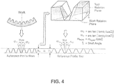
- the reference profile of the tool is determined from the reference profile of the work applying the procedure shown in Figure 4 .
- the reference profile of the work with its pressure angles ⁇ 1 and ⁇ 2 and its point width Wp is drawn as a trapezoidal channel which is cut with a plane under the shaft angle ⁇ ( Figure 4 , top, right side).
- the profile which is defined by the intersecting lines between plane and channel represents the reference profile of the tool.
- This tool reference profile is used in order to generate the involute in the tool cutting front ( Figure 4 , bottom right side).
- the cutting takes place below or above the work gear center line in order to keep the B-axis angle below 90°.
- the crossing point between the cutter axis and the work axis lies in the cutter reference plane.
- the first cutter (left) is a shaft type which is slightly tapered without helix angle in the cutting teeth. This cutter can be used for gears with a helix angle.
- the shaft angle between cutter and work will be set to the helix angle of the work. This also means that the helix angle of the work should be above 10° in order to generate sufficient cutting speed. Due to the straight nature of the cutting teeth, work pieces with small diameter and large face width might cause interferences between the slot and the far end of the cutting blade.
- the skiving cutter in the center of Figure 6 is a wafer-type cutter (preferably with TiN coating) which can be re-sharpened a few times.
- the cutting teeth are also straight, which makes this cutter also only suitable for work pieces with a helix angle.
- the wafer cutter has very short relieved teeth, which will prevent interference problems in case of helical slots that wind around a small diameter work piece.
- the skiving cutter to the right of Figure 6 has serrated blade front faces and teeth which are oriented under a helix angle.
- the skiving cutter of Figure 6 , right is coated with a TiAIN coating.
- the formula is simplified to the first special case.
- the lower graphic shows the formula simplification for the second special case, which occurs if the helix angle ⁇ is equal the shaft angle ⁇ .
- the cutting velocity formula considers next to the circumferential velocity at the work gear pitch diameter the helix angle ⁇ of the work and the shaft angle ⁇ between work and skiving cutter.
- the cutting velocity vector is automatically directed in the flank lead direction if the formula in Figure 7 is applied.
- the formula indicates some interplay between ⁇ and ⁇ , the major parameter for generation of sufficient cutting velocity is the shaft angle ⁇ between the work and tool axes.
- a cutter head 2 which uses stick blades 4 has been developed especially for skiving (see Figure 8a - 8c ).
- the blade material is preferably carbide and the blade profiles are 3-face ground and all-around coated preferably with TiAIN (titanium aluminum nitride) coating although other coatings are not excluded.
- the blade profile 6 resembles an involute which is derived from the tool reference profile in Figure 4 .
- the blades can either be ground as full profile blades just like the profiles of the cutters shown in Figure 6 , or as alternating left flank - right flank blades which allows it to realize sufficient side rake angles.
- the alternate blade arrangement offers very good tool life and an exceptionally smooth cutting operation. However, the productivity is slightly lower than the one using full profile blades.
- the preferred cutter of the present invention is illustrated in Figure 8c and comprises a cutter head 2 having a front face 3 and a back face 5 with a plurality of cutter blade mounting and positioning slots (blade slots) 8 arranged spaced, preferably equidistant, about the periphery 7 of the cutter head.
- the blade slots 8, and hence the cutting blades 4 are preferably oriented perpendicular to the axis of rotation, A, of the cutter head but may be inclined from the perpendicular by less than 50 degrees, preferably less than 20 degrees, thereby forming a conical shaped cutter.
- the blade slots may be positioned to extend radially from the cutter head axis whereby the longitudinal axis of a cutter blade will intersect the cutter head axis A ( Figure 10 ), or the blade slots may be radially offset from the cutter head axis.
- the blade slots may have any cross-sectional shape such as square, rectangular or those types having generally V-shaped seating surfaces 10 comprising a pair of angled mounting surfaces 12, 14 each less than 90 degrees (e.g. see US 5,890,846 ).
- the cutting blade of the present invention has its cutting face 16 formed in a surface of the cutting blade 4 that is located opposite of the seating surfaces 13, 15 of the cutting blade (see blade cross-sectional view Figure 8d ) and, hence, also opposite of the V-shaped seating surfaces 12, 14 of cutter head 2 when the cutting blade 4 is mounted in the cutter head.
- the V-shaped seating surfaces 12, 14 open-up in a direction toward the front face 3 and the cutting faces 16 of the cutting blades 4 are oriented generally toward the front face 3.
- forces encountered during cutting are transmitted to the V-shaped seating surfaces 12, 14 thereby fortifying the seating of the cutting blades 4 in the cutter head 2 resulting in a cutting tool of enhanced stability during the cutting process.
- any side rake and relief angles have been omitted for simplicity of viewing and angle K (see Figure 8c also) is the cutting face angle of blade 4 which is generally equal to the shaft angle ⁇ .
- the blades Due to the design of the cutter head of Figures 8a - 8c , the blades have spaces between them which are larger than the tooth thickness of the reference profile.
- the cutters may be configured for a certain module of gear, such that the blades in the cutter head represent every second, third or fourth slot of the reference profile.
- the developed stick blade system allows adjustment of the blade stick in or out by some small amount to match the required pitch diameter for the number of teeth selected.
- the preferred cutter heads within the 9 inch size family of cutters usually comprise blade slot numbers of 15, 17, 19, 21 or 23.
- all existing integer fractions between 2 and 5 are determined (the range may be expanded to 6, 7, 8 or more).
- the goal is to find the largest number of slots which is available in the 9 inch diameter line of cutters to assure the maximal productivity.
- the skiving cutter never represents the theoretical tool tooth number with the number of slots but only a fraction thereof.
- the theoretical number of tool teeth becomes the virtual tool tooth number of which only a fraction is represented on the cutter head. If a number is selected and typed in the spread sheet, next to the actual fraction of slot and theoretical tooth number the resulting number of cutter slots is shown in the last column.
- the virtual number of tool teeth may be even and never is a prime number. This will not be of any disadvantage, as long as a hunting tooth relationship between work and virtual cutter is given. In such cases, also between work and real cutter, the hunting tooth principle exists.
- the peripheral stick blade cutter design will physically not allow the virtual number of blades to fit next to each other.
- the cutter of Figure 10 represents each other tooth which is indicated with the dashed drawn (virtual) blades between the real blades.
- Solid cutters made from high speed steel (HSS), such as M48, with a TiAIN coating are generally suitable for a surface speed of up to about 100 m/min in a wet skiving environment.
- Carbide stick blades (e.g. 10%Co-90%WC) with a TiAIN coating allow about 300 m/min surface speed which may be considered to be a "critical speed".
- critical speed e.g. 10%Co-90%WC
- This creates a profile sliding which is superimposed on the cutting speed.
- the profile sliding has its highest value at the blade tip which also undergoes a long chip removing engagement path and thereby resulting in the blade tip being vulnerable to additional side relief wear.
- a module 4.0 mm gear was cut by wet UCS skiving with TiAIN coated carbide blades and 172 m/min surface speed.
- a first roughing pass used an infeed setting of 5 mm and a feed rate of 0.045 mm per blade.
- the chips were large and only slightly curved. Each chip represents one flank and part of the tooth slot bottom.
- a second pass used an infeed setting of 3 mm and a feed rate of 0.28 mm per blade. This chip consisted of two flanks connected by a bottom portion.
- a finishing pass used an infeed of 1.00 mm and a feed rate of 0.015 mm per blade. This chip also had two flanks and a bottom chip portion connected to a form U-shaped appearance.
- the same type of gear was cut utilizing TiAIN coated carbide blades and 172 m/min surface speed in a three-pass dry cutting process using the same infeed values and feed rates as applied in the wet cutting. Except for a color change due process heat, the dry chips generally have the same appearance as the chips from wet cutting.
- the comparison between the wet and dry skiving processes with coated carbide stick blades shows the dry process as being advantageous.
- the process heat helps to plastically deform the chip during the shearing action. If the process parameters and tool geometry are chosen to move the process heat into the chips and then away from tool and work piece with the chips, a cool skiving process is the result. Dry skiving delivers a better surface finish and causes equal or even lesser tool wear than the "wet" process version. Additionally, the chip surface on the side adjacent to the sheared off side is smoother and machine power readings showed about 15% lower spindle power during dry skiving. The current skiving developments indicate that dry skiving delivers a better tool life, which is anticipated to be even more significant than in dry cutting of bevel gears.
- Dry UCS skiving with coated carbide blades results in the optimal combination between low tool wear and low skiving times.
- An additional advantage is that machines with medium speed high-torque spindles (e.g. 1000 RPM maximum for machine size 600 mm Outside Diameter) can be applied without compromising the performance of the machine e.g. for bevel gears which require low RPM and high torque.
- This advantage is important if a manufacturer performs skiving on bevel gear cutting machines. The manufacturer expects appropriate machine performance for all bevel gear machining but also appreciates the ability to practice an efficient skiving process on the same machine.
- FIG. 11 A productivity comparison between the traditional processes hobbing and shaping and three variations of the skiving process is shown in Figure 11 .
- an external ring gear with the gear data as those in the above examples was used for all processes.
- the objective was a finishing quality with scallop or generating flat amplitudes at or below 5 ⁇ m.
- the shaping process used a TiAIN coated shaper cutter from HSS material with 34 teeth and was setup as a 3-cut finishing cycle.
- the identical shaper cutter was used for the wet skiving where the cutting was done in four passes.
- a one-start hob with 16 gashes also from TiAIN coated HSS material was utilized in a 2-cut cycle.
- Dry skiving with TiAIN coated H10F carbide blades is represented in the diagram as UCS-skiving with 172 m/min and as high speed skiving with 300 m/min, both setup as a three pass cycle.
- the dry skiving bars are based on a 24 blade and 9" diameter cutter head.
- the chip thickness in the case of UCS-skiving is 10% to 20% higher than in the case of high speed skiving which reduces the productivity difference between the two process variations and yet gives the UCS-skiving a tool life advantage.
- Figure 11 indicates that skiving has between 6 to 12 times the productivity of shaping and between 1.6 and 3.3 times the productivity of hobbing.
Landscapes
- Engineering & Computer Science (AREA)
- Mechanical Engineering (AREA)
- Gear Processing (AREA)
- Milling Processes (AREA)
- Drilling Tools (AREA)
Claims (12)
- Schneidkopf (2) zum Wälzschälen von Zahnrädern, wobei der Schneidkopf um eine Drehachse (A) herum drehbar ist und umfasst:eine vordere Fläche (3) und eine hintere Fläche (5),eine Umfangsfläche (7), die sich zwischen der vorderen Fläche und der hinteren Fläche befindet, wobei die Umfangsfläche eine Mehrzahl von Schneidklingenmontage- und Positionierungsschlitzen (8) umfasst, die darin angeordnet sind und sich in einer Längsrichtung nach innen in Richtung der Schneidkopfachse erstrecken, dadurch gekennzeichnet, dass jeder der Schneidklingenmontage- und Positionierungsschlitze Auflageflächen (10) umfasst, die im Allgemeinen eine V-Form definieren, welche sich zu der vorderen Fläche hin öffnet.
- Schneidkopf nach Anspruch 1, der weiterhin eine Schneidklinge (4) umfasst, welche sich in wenigstens einem aus der Mehrzahl von Schneidklingenmontage- und Positionierungsschlitzen (8) befindet,
wobei die Schneidklinge stabförmig ist mit einer Länge, die sich in einer Längsrichtung erstreckt, und eine Schneidfläche (16) umfasst, die sich an einem Ende der Länge befindet, wobei die Schneidfläche von der Umfangsfläche hervorsteht und in einer Richtung zu der vorderen Fläche hin ausgerichtet ist,
wobei die Schneidklinge weiterhin ein Paar von abgewinkelten Montageflächen (13, 15) umfasst, die im Allgemeinen eine V-Form definieren und sich wenigstens an einem Abschnitt der Länge entlang erstrecken, wobei die Schneidfläche gegenüber von dem Paar von abgewinkelten Montageflächen ausgerichtet ist,
wobei das Paar von abgewinkelten Montageflächen in und ergänzend zu der V-Form der Auflageflächen des Schneidkopfes angeordnet ist. - Schneidkopf nach Anspruch 1, wobei die Längsrichtung der Mehrzahl von Schneidklingenmontage- und Positionierungsschlitzen die Drehachse des Schneidkopfes schneidet.
- Schneidkopf nach Anspruch 1, wobei die Längsrichtung der Mehrzahl von Schneidklingenmontage- und Positionierungsschlitzen in Bezug auf die Drehachse des Schneidkopfes radial versetzt ist.
- Schneidkopf nach Anspruch 1, wobei die Mehrzahl von Schneidklingenmontage- und Positionierungsschlitzen rechtwinklig zu der Drehachse des Schneidkopfes ausgerichtet ist.
- Schneidkopf nach Anspruch 5, wobei die Mehrzahl von Schneidklingenmontage- und Positionierungsschlitzen in Bezug auf die Drehachse des Schneidkopfes in einem Winkel ausgerichtet sind, der weniger als 50 Grad von einem rechten Winkel abweicht.
- Schneidkopf nach Anspruch 6, wobei die Mehrzahl von Schneidklingenmontage- und Positionierungsschlitzen in Bezug auf die Drehachse des Schneidkopfes in einem Winkel ausgerichtet sind, der weniger als 20 Grad von einem rechten Winkel abweicht.
- Schneidklinge (4) zum Wälzschälen von Zahnrädern, wobei die Schneidklinge umfasst:eine Stabform mit einer Länge, die sich in einer Längsrichtung erstreckt, und umfassend eine Schneidfläche (16), die sich an einem Ende der Länge befindet, dadurch gekennzeichnet, dass die Schneidklinge weiterhin ein Paar von abgewinkelten Montageflächen (13, 15) umfasst, die im Allgemeinen eine V-Form definieren und sich wenigstens an einem Abschnitt der Länge entlang erstrecken, wobei die Schneidfläche (16) gegenüber von dem Paar von abgewinkelten Montageflächen ausgerichtet ist.
- Verfahren zur Fertigung eines gezahnten Werkstücks mittels Wälzschälen, wobei das Verfahren umfasst:Bereitstellen eines Werkzeugs, das einen Schneidkopf (2) umfasst, wobei der Schneidkopf um eine Drehachse (A) herum drehbar ist und umfasst: eine vordere Fläche (3), eine hintere Fläche (5) und eine Umfangsfläche (7), die sich zwischen der vorderen Fläche und der hinteren Fläche befindet, wobei die Umfangsfläche eine Mehrzahl von Schneidklingenmontage- und Positionierungsschlitzen (8) umfasst, die darin angeordnet sind und sich in einer Längsrichtung nach innen in Richtung der Schneidkopfachse erstrecken, wobei jeder der Schneidklingenmontage- und Positionierungsschlitze Auflageflächen (10) umfasst,Bereitstellen einer Schneidklinge (4), welche sich in wenigstens einem aus der Mehrzahl von Schneidklingenmontage- und Positionierungsschlitzen befindet, wobei die Schneidklinge stabförmig ist mit einer Länge, die sich in einer Längsrichtung erstreckt, und eine Schneidfläche umfasst, die sich an einem Ende der Länge befindet, wobei die Schneidfläche von der Umfangsfläche hervorsteht und in einer Richtung zu der vorderen Fläche hin ausgerichtet ist,in Kontakt Bringen des Werkzeugs mit dem Werkstück,Ausarbeiten von Zähnen an dem Werkstück mittels Wälzschälen, dadurch gekennzeichnet, dass jeder der Schneidklingenmontage- und Positionierungsschlitze Auflageflächen umfasst, die im Allgemeinen eine V-Form definieren, welche sich zu der vorderen Fläche hin öffnet,wobei die Schneidklinge weiterhin ein Paar von abgewinkelten Montageflächen (13, 15) umfasst, die im Allgemeinen eine V-Form definieren und sich wenigstens an einem Abschnitt der Länge entlang erstrecken, wobei die Schneidfläche gegenüber von dem Paar von abgewinkelten Montageflächen ausgerichtet ist, wobei das Paar von abgewinkelten Montageflächen in und ergänzend zu der V-Form der Auflageflächen (10) des Schneidkopfes angeordnet ist.
- Verfahren nach Anspruch 9, wobei das Ausarbeiten bei einer Oberflächengeschwindigkeit von 150 bis 200 m/min durchgeführt wird.
- Verfahren nach Anspruch 9, wobei die Schneidklinge Karbid umfasst.
- Verfahren nach Anspruch 9, wobei die Schneidklinge mit TiAlN beschichtet ist.
Applications Claiming Priority (2)
| Application Number | Priority Date | Filing Date | Title |
|---|---|---|---|
| US201361814529P | 2013-04-22 | 2013-04-22 | |
| PCT/US2014/034813 WO2014176169A2 (en) | 2013-04-22 | 2014-04-21 | Skiving of cylindrical gears |
Publications (2)
| Publication Number | Publication Date |
|---|---|
| EP2988898A2 EP2988898A2 (de) | 2016-03-02 |
| EP2988898B1 true EP2988898B1 (de) | 2019-01-16 |
Family
ID=50771646
Family Applications (1)
| Application Number | Title | Priority Date | Filing Date |
|---|---|---|---|
| EP14725890.9A Active EP2988898B1 (de) | 2013-04-22 | 2014-04-21 | Wälzschälen von zylindrischen zahnrädern |
Country Status (7)
| Country | Link |
|---|---|
| US (2) | US9956627B2 (de) |
| EP (1) | EP2988898B1 (de) |
| JP (1) | JP6557215B2 (de) |
| KR (1) | KR102064893B1 (de) |
| CN (1) | CN105121082B (de) |
| BR (1) | BR112015026236A2 (de) |
| WO (1) | WO2014176169A2 (de) |
Families Citing this family (22)
| Publication number | Priority date | Publication date | Assignee | Title |
|---|---|---|---|---|
| JP6340764B2 (ja) * | 2013-08-08 | 2018-06-13 | 株式会社ジェイテクト | 歯車加工装置 |
| EP3041633B1 (de) * | 2013-09-04 | 2021-04-28 | The Gleason Works | Randschneidewerkzeug mit stielklingen |
| DE102015106354A1 (de) * | 2014-12-16 | 2016-06-16 | Profilator Gmbh & Co. Kg | Wälzschälverfahren und Schneidwerkzeug zur Erzeugung zumindest teilverrundeter Zahnköpfe |
| JP6062971B2 (ja) | 2015-01-21 | 2017-01-18 | ファナック株式会社 | スカイビング加工指令に基づいて工作機械を制御する数値制御装置 |
| DE102015202760A1 (de) * | 2015-02-16 | 2016-08-18 | Zf Friedrichshafen Ag | Werkzeug und Verfahren zum Entfernen von Spänen aus einem Werkstück |
| DE102015120556A1 (de) * | 2015-03-24 | 2016-09-29 | Profilator Gmbh & Co. Kg | Verfahren und Vorrichtung zum Feinbearbeiten verzahnter und gehärteter Werkräder |
| LU93122B1 (de) * | 2016-06-27 | 2018-01-09 | Ovalo Gmbh | Zahnrad, Verfahren zum Herstellen der Verzahnung eines Zahnrades, sowie Werkzeugzahnrad zum Herstellen der Verzahnung eines Zahnrades |
| CN109641296B (zh) * | 2016-08-22 | 2021-01-15 | 格里森工场 | 在工具几何形状不变的情况下的强力刮齿压力角校正 |
| CN106735614A (zh) * | 2016-12-23 | 2017-05-31 | 江苏大学 | 一种用于强力车齿技术的锥形多刃齿形刀具 |
| EP3354389A1 (de) * | 2017-01-30 | 2018-08-01 | Sandvik Intellectual Property AB | Verfahren zur bearbeitung von kugelbahnen von gleichlaufgelenke |
| JP6673260B2 (ja) * | 2017-02-24 | 2020-03-25 | トヨタ自動車株式会社 | 歯車部材およびその製造方法 |
| DE102017003648A1 (de) * | 2017-04-13 | 2018-10-18 | Liebherr-Verzahntechnik Gmbh | Verfahren zur Verzahnbearbeitung eines Werkstücks |
| CN109262078A (zh) * | 2017-07-17 | 2019-01-25 | 昆山光腾智能机械有限公司 | 加工减速机针齿壳内齿的车齿刀具及加工方法 |
| JP6944302B2 (ja) * | 2017-08-04 | 2021-10-06 | 三菱重工業株式会社 | 切削工具 |
| DE102018112865B3 (de) * | 2018-05-29 | 2019-10-17 | Hartmetall-Werkzeugfabrik Paul Horn Gmbh | Wälzschälwerkzeug |
| WO2020132228A1 (en) | 2018-12-21 | 2020-06-25 | The Gleason Works | Independent pressure angle corrections for power skiving |
| JP6762588B1 (ja) * | 2019-09-04 | 2020-09-30 | 九州精密工業株式会社 | スカイビングカッタ |
| WO2021078583A1 (en) * | 2019-10-23 | 2021-04-29 | Esko-Graphics Kongsberg As | Automatically adjustable system for cutting at variable notch angles |
| CN111922445B (zh) * | 2020-06-18 | 2023-06-30 | 西安理工大学 | 一种锥形珩轮及珩齿加工方法 |
| DE102021102098A1 (de) * | 2021-01-29 | 2022-08-04 | Präwema Antriebstechnik GmbH | Werkzeug und Verfahren zum Erzeugen von Hinterlegungen an den Zähnen einer Verzahnung eines Zahnrads |
| KR102916192B1 (ko) | 2021-08-19 | 2026-01-22 | 주식회사 디엔솔루션즈 | 복합공작기계의 기어 스카이빙 가공 제어방법 |
| CN114453630B (zh) * | 2022-01-20 | 2023-04-04 | 湖北文理学院 | 控制机床铣削不粘刀的方法、装置、电子设备和存储介质 |
Family Cites Families (24)
| Publication number | Priority date | Publication date | Assignee | Title |
|---|---|---|---|---|
| DE243514C (de) | 1910-03-01 | 1912-02-16 | George Adams | Verfahren zum schneiden van zahnrädern mittels eines zahnradartigen, an den stirnflächen der zähne mit schneidkanten versehenen schneidwerkzeuges |
| DE333651C (de) * | 1918-06-08 | 1921-03-01 | Hugo Lorand | Zahnradartiges Werkzeug zum Stossen von Zahnraedern nach dem Fellows-Verfahren |
| FR947074A (fr) * | 1947-05-16 | 1949-06-22 | Fraise à outils mobiles multiples | |
| US3931754A (en) * | 1974-11-12 | 1976-01-13 | Kabushiki Kaisha Komatsu Seisakusho | Skiving cutter device for use in cutting internal spur gear |
| JPS59124516A (ja) * | 1982-12-28 | 1984-07-18 | Azumi Kk | 植刃式超硬ピニオンカツタ |
| US4575285A (en) * | 1984-11-19 | 1986-03-11 | The Gleason Works | Cutting tool and method of manufacture |
| EP0912285B1 (de) | 1996-04-25 | 2003-05-14 | The Gleason Works | Schneidwerkzeug für verzahnte gegenstände |
| US5890946A (en) | 1997-05-29 | 1999-04-06 | Bloomfield; Steven L. | Twirling toy |
| JPH1159126A (ja) * | 1997-08-21 | 1999-03-02 | Okamoto Ind Inc | 床走行用タイヤカバー |
| WO1999041035A1 (en) * | 1998-02-11 | 1999-08-19 | The Gleason Works | Cutting tool for producing toothed articles |
| JP2000233320A (ja) * | 1999-02-12 | 2000-08-29 | Mitsubishi Heavy Ind Ltd | 乾式加工用歯車加工工具及び乾式加工用歯車加工工具の皮膜形成方法及び乾式加工用歯車加工工具の皮膜形成装置。 |
| US6626613B2 (en) * | 1999-04-19 | 2003-09-30 | Jeffrey D. Russell | Cutting tool |
| DE19953089A1 (de) | 1999-11-04 | 2001-05-17 | Daimler Chrysler Ag | Erzeugung periodischer Strukturen auf rotationssymmetrischen Bauteilen |
| US6669415B2 (en) | 2001-02-16 | 2003-12-30 | The Gleason Works | Machine for producing bevel gears |
| US7059810B2 (en) * | 2002-04-18 | 2006-06-13 | Kennametal Inc. | Gear hobbing cutter system |
| US7736099B2 (en) * | 2005-12-16 | 2010-06-15 | Cole Carbide Industries, Inc. | Gear milling tool with replaceable cutting inserts |
| KR101432847B1 (ko) * | 2006-09-26 | 2014-08-26 | 오를리콘 트레이딩 아크티엔게젤샤프트, 트뤼프바흐 | 하드 코팅을 가지는 작업편 |
| DE102008037514B4 (de) | 2008-11-03 | 2024-06-20 | Profilator Gmbh & Co. Kg | Wälzschälvorrichtung und -verfahren |
| DE102009025945A1 (de) * | 2009-06-10 | 2010-12-16 | Profilator Gmbh & Co. Kg | Vorrichtung und Verfahren zum Wälzschälen von innenverzahnten Zahnrädern sowie zugehöriges Schälrad |
| JP5776924B2 (ja) * | 2010-08-31 | 2015-09-09 | アイシン精機株式会社 | 歯車加工装置、カッター、及び波動歯車装置 |
| DE102010042835A1 (de) * | 2010-10-22 | 2012-04-26 | Sandvik Intellectual Property Ab | Zahnfräser und Verfahren zum Fräsen der Zähne von Zahngetriebeelementen |
| DE202011050054U1 (de) * | 2011-05-06 | 2011-09-15 | Klingelnberg Ag | Wälzschälwerkzeug mit Messerstäben |
| EP2570217B1 (de) * | 2011-09-15 | 2014-11-05 | Klingelnberg AG | Semi-Completing Wälzschälverfahren und Vorrichtung mit entsprechendem Wälzschälwerkzeug zum Ausführen eines Semi-Completing Wälzschälverfahrens |
| EP3041633B1 (de) * | 2013-09-04 | 2021-04-28 | The Gleason Works | Randschneidewerkzeug mit stielklingen |
-
2014
- 2014-04-21 EP EP14725890.9A patent/EP2988898B1/de active Active
- 2014-04-21 BR BR112015026236A patent/BR112015026236A2/pt active Search and Examination
- 2014-04-21 KR KR1020157031205A patent/KR102064893B1/ko not_active Expired - Fee Related
- 2014-04-21 WO PCT/US2014/034813 patent/WO2014176169A2/en not_active Ceased
- 2014-04-21 US US14/781,753 patent/US9956627B2/en active Active
- 2014-04-21 CN CN201480022512.6A patent/CN105121082B/zh active Active
- 2014-04-21 JP JP2016510720A patent/JP6557215B2/ja active Active
-
2018
- 2018-03-23 US US15/933,580 patent/US10471527B2/en active Active
Non-Patent Citations (1)
| Title |
|---|
| None * |
Also Published As
| Publication number | Publication date |
|---|---|
| WO2014176169A3 (en) | 2015-02-26 |
| WO2014176169A2 (en) | 2014-10-30 |
| BR112015026236A2 (pt) | 2017-07-25 |
| US20180207736A1 (en) | 2018-07-26 |
| US20160016242A1 (en) | 2016-01-21 |
| US9956627B2 (en) | 2018-05-01 |
| KR20150143547A (ko) | 2015-12-23 |
| EP2988898A2 (de) | 2016-03-02 |
| JP2016516602A (ja) | 2016-06-09 |
| KR102064893B1 (ko) | 2020-01-10 |
| JP6557215B2 (ja) | 2019-08-07 |
| US10471527B2 (en) | 2019-11-12 |
| CN105121082A (zh) | 2015-12-02 |
| CN105121082B (zh) | 2017-09-19 |
Similar Documents
| Publication | Publication Date | Title |
|---|---|---|
| US10471527B2 (en) | Skiving of cylindrical gears | |
| Stadtfeld | Power skiving of cylindrical gears on different machine platforms | |
| US8950301B2 (en) | Skiving tool comprising cutter bars | |
| CN103635280B (zh) | 用于刮齿加工外齿部的方法以及具有相应的刮齿刀具的设备 | |
| US10239139B2 (en) | Method for machining a set of teeth, tool arrangement, and tooth-cutting machine | |
| EP3200948B1 (de) | Axialer walzfräser mit schneidzähnen mit mehrfachumdrehung und verfahren zur herstellung eines zahnrads mittels eines walzfräsers | |
| EP2152459B1 (de) | Werkzeug für verbesserten chip-fluss | |
| CA3012158C (en) | Milling tool | |
| AU4711900A (en) | Cutting tool for producing gears by face hobbing | |
| CN107755826B (zh) | 用于机械加工面联接工件的齿面的方法 | |
| US20180243849A1 (en) | Method and tool for manufacturing spiral tooth face couplings | |
| EP3352937B1 (de) | Kompatibilität von dreiseitigen klingen | |
| US20180056417A1 (en) | Method for machining the tooth flanks of face coupling workpieces in the semi-completing method | |
| JP7628077B2 (ja) | パワースカイビングのための独立した圧力角補正 |
Legal Events
| Date | Code | Title | Description |
|---|---|---|---|
| PUAI | Public reference made under article 153(3) epc to a published international application that has entered the european phase |
Free format text: ORIGINAL CODE: 0009012 |
|
| 17P | Request for examination filed |
Effective date: 20151001 |
|
| AK | Designated contracting states |
Kind code of ref document: A2 Designated state(s): AL AT BE BG CH CY CZ DE DK EE ES FI FR GB GR HR HU IE IS IT LI LT LU LV MC MK MT NL NO PL PT RO RS SE SI SK SM TR |
|
| AX | Request for extension of the european patent |
Extension state: BA ME |
|
| DAX | Request for extension of the european patent (deleted) | ||
| GRAP | Despatch of communication of intention to grant a patent |
Free format text: ORIGINAL CODE: EPIDOSNIGR1 |
|
| STAA | Information on the status of an ep patent application or granted ep patent |
Free format text: STATUS: GRANT OF PATENT IS INTENDED |
|
| INTG | Intention to grant announced |
Effective date: 20181108 |
|
| GRAS | Grant fee paid |
Free format text: ORIGINAL CODE: EPIDOSNIGR3 |
|
| GRAA | (expected) grant |
Free format text: ORIGINAL CODE: 0009210 |
|
| STAA | Information on the status of an ep patent application or granted ep patent |
Free format text: STATUS: THE PATENT HAS BEEN GRANTED |
|
| AK | Designated contracting states |
Kind code of ref document: B1 Designated state(s): AL AT BE BG CH CY CZ DE DK EE ES FI FR GB GR HR HU IE IS IT LI LT LU LV MC MK MT NL NO PL PT RO RS SE SI SK SM TR |
|
| REG | Reference to a national code |
Ref country code: GB Ref legal event code: FG4D |
|
| REG | Reference to a national code |
Ref country code: CH Ref legal event code: EP |
|
| REG | Reference to a national code |
Ref country code: IE Ref legal event code: FG4D |
|
| REG | Reference to a national code |
Ref country code: DE Ref legal event code: R096 Ref document number: 602014039985 Country of ref document: DE |
|
| REG | Reference to a national code |
Ref country code: CH Ref legal event code: NV Representative=s name: WERNER FENNER PATENTANWALT, CH Ref country code: AT Ref legal event code: REF Ref document number: 1089343 Country of ref document: AT Kind code of ref document: T Effective date: 20190215 |
|
| REG | Reference to a national code |
Ref country code: NL Ref legal event code: MP Effective date: 20190116 |
|
| REG | Reference to a national code |
Ref country code: LT Ref legal event code: MG4D |
|
| PG25 | Lapsed in a contracting state [announced via postgrant information from national office to epo] |
Ref country code: NL Free format text: LAPSE BECAUSE OF FAILURE TO SUBMIT A TRANSLATION OF THE DESCRIPTION OR TO PAY THE FEE WITHIN THE PRESCRIBED TIME-LIMIT Effective date: 20190116 |
|
| REG | Reference to a national code |
Ref country code: AT Ref legal event code: MK05 Ref document number: 1089343 Country of ref document: AT Kind code of ref document: T Effective date: 20190116 |
|
| PG25 | Lapsed in a contracting state [announced via postgrant information from national office to epo] |
Ref country code: PT Free format text: LAPSE BECAUSE OF FAILURE TO SUBMIT A TRANSLATION OF THE DESCRIPTION OR TO PAY THE FEE WITHIN THE PRESCRIBED TIME-LIMIT Effective date: 20190516 Ref country code: ES Free format text: LAPSE BECAUSE OF FAILURE TO SUBMIT A TRANSLATION OF THE DESCRIPTION OR TO PAY THE FEE WITHIN THE PRESCRIBED TIME-LIMIT Effective date: 20190116 Ref country code: NO Free format text: LAPSE BECAUSE OF FAILURE TO SUBMIT A TRANSLATION OF THE DESCRIPTION OR TO PAY THE FEE WITHIN THE PRESCRIBED TIME-LIMIT Effective date: 20190416 Ref country code: LT Free format text: LAPSE BECAUSE OF FAILURE TO SUBMIT A TRANSLATION OF THE DESCRIPTION OR TO PAY THE FEE WITHIN THE PRESCRIBED TIME-LIMIT Effective date: 20190116 Ref country code: FI Free format text: LAPSE BECAUSE OF FAILURE TO SUBMIT A TRANSLATION OF THE DESCRIPTION OR TO PAY THE FEE WITHIN THE PRESCRIBED TIME-LIMIT Effective date: 20190116 Ref country code: SE Free format text: LAPSE BECAUSE OF FAILURE TO SUBMIT A TRANSLATION OF THE DESCRIPTION OR TO PAY THE FEE WITHIN THE PRESCRIBED TIME-LIMIT Effective date: 20190116 Ref country code: PL Free format text: LAPSE BECAUSE OF FAILURE TO SUBMIT A TRANSLATION OF THE DESCRIPTION OR TO PAY THE FEE WITHIN THE PRESCRIBED TIME-LIMIT Effective date: 20190116 |
|
| PG25 | Lapsed in a contracting state [announced via postgrant information from national office to epo] |
Ref country code: BG Free format text: LAPSE BECAUSE OF FAILURE TO SUBMIT A TRANSLATION OF THE DESCRIPTION OR TO PAY THE FEE WITHIN THE PRESCRIBED TIME-LIMIT Effective date: 20190416 Ref country code: HR Free format text: LAPSE BECAUSE OF FAILURE TO SUBMIT A TRANSLATION OF THE DESCRIPTION OR TO PAY THE FEE WITHIN THE PRESCRIBED TIME-LIMIT Effective date: 20190116 Ref country code: IS Free format text: LAPSE BECAUSE OF FAILURE TO SUBMIT A TRANSLATION OF THE DESCRIPTION OR TO PAY THE FEE WITHIN THE PRESCRIBED TIME-LIMIT Effective date: 20190516 Ref country code: GR Free format text: LAPSE BECAUSE OF FAILURE TO SUBMIT A TRANSLATION OF THE DESCRIPTION OR TO PAY THE FEE WITHIN THE PRESCRIBED TIME-LIMIT Effective date: 20190417 Ref country code: LV Free format text: LAPSE BECAUSE OF FAILURE TO SUBMIT A TRANSLATION OF THE DESCRIPTION OR TO PAY THE FEE WITHIN THE PRESCRIBED TIME-LIMIT Effective date: 20190116 Ref country code: RS Free format text: LAPSE BECAUSE OF FAILURE TO SUBMIT A TRANSLATION OF THE DESCRIPTION OR TO PAY THE FEE WITHIN THE PRESCRIBED TIME-LIMIT Effective date: 20190116 |
|
| REG | Reference to a national code |
Ref country code: DE Ref legal event code: R097 Ref document number: 602014039985 Country of ref document: DE |
|
| PG25 | Lapsed in a contracting state [announced via postgrant information from national office to epo] |
Ref country code: RO Free format text: LAPSE BECAUSE OF FAILURE TO SUBMIT A TRANSLATION OF THE DESCRIPTION OR TO PAY THE FEE WITHIN THE PRESCRIBED TIME-LIMIT Effective date: 20190116 Ref country code: SK Free format text: LAPSE BECAUSE OF FAILURE TO SUBMIT A TRANSLATION OF THE DESCRIPTION OR TO PAY THE FEE WITHIN THE PRESCRIBED TIME-LIMIT Effective date: 20190116 Ref country code: DK Free format text: LAPSE BECAUSE OF FAILURE TO SUBMIT A TRANSLATION OF THE DESCRIPTION OR TO PAY THE FEE WITHIN THE PRESCRIBED TIME-LIMIT Effective date: 20190116 Ref country code: EE Free format text: LAPSE BECAUSE OF FAILURE TO SUBMIT A TRANSLATION OF THE DESCRIPTION OR TO PAY THE FEE WITHIN THE PRESCRIBED TIME-LIMIT Effective date: 20190116 Ref country code: AT Free format text: LAPSE BECAUSE OF FAILURE TO SUBMIT A TRANSLATION OF THE DESCRIPTION OR TO PAY THE FEE WITHIN THE PRESCRIBED TIME-LIMIT Effective date: 20190116 Ref country code: AL Free format text: LAPSE BECAUSE OF FAILURE TO SUBMIT A TRANSLATION OF THE DESCRIPTION OR TO PAY THE FEE WITHIN THE PRESCRIBED TIME-LIMIT Effective date: 20190116 |
|
| PLBE | No opposition filed within time limit |
Free format text: ORIGINAL CODE: 0009261 |
|
| STAA | Information on the status of an ep patent application or granted ep patent |
Free format text: STATUS: NO OPPOSITION FILED WITHIN TIME LIMIT |
|
| PG25 | Lapsed in a contracting state [announced via postgrant information from national office to epo] |
Ref country code: SM Free format text: LAPSE BECAUSE OF FAILURE TO SUBMIT A TRANSLATION OF THE DESCRIPTION OR TO PAY THE FEE WITHIN THE PRESCRIBED TIME-LIMIT Effective date: 20190116 |
|
| REG | Reference to a national code |
Ref country code: BE Ref legal event code: MM Effective date: 20190430 |
|
| 26N | No opposition filed |
Effective date: 20191017 |
|
| GBPC | Gb: european patent ceased through non-payment of renewal fee |
Effective date: 20190421 |
|
| PG25 | Lapsed in a contracting state [announced via postgrant information from national office to epo] |
Ref country code: LU Free format text: LAPSE BECAUSE OF NON-PAYMENT OF DUE FEES Effective date: 20190421 Ref country code: MC Free format text: LAPSE BECAUSE OF FAILURE TO SUBMIT A TRANSLATION OF THE DESCRIPTION OR TO PAY THE FEE WITHIN THE PRESCRIBED TIME-LIMIT Effective date: 20190116 |
|
| PG25 | Lapsed in a contracting state [announced via postgrant information from national office to epo] |
Ref country code: GB Free format text: LAPSE BECAUSE OF NON-PAYMENT OF DUE FEES Effective date: 20190421 |
|
| PG25 | Lapsed in a contracting state [announced via postgrant information from national office to epo] |
Ref country code: SI Free format text: LAPSE BECAUSE OF FAILURE TO SUBMIT A TRANSLATION OF THE DESCRIPTION OR TO PAY THE FEE WITHIN THE PRESCRIBED TIME-LIMIT Effective date: 20190116 Ref country code: FR Free format text: LAPSE BECAUSE OF NON-PAYMENT OF DUE FEES Effective date: 20190430 Ref country code: BE Free format text: LAPSE BECAUSE OF NON-PAYMENT OF DUE FEES Effective date: 20190430 |
|
| PG25 | Lapsed in a contracting state [announced via postgrant information from national office to epo] |
Ref country code: TR Free format text: LAPSE BECAUSE OF FAILURE TO SUBMIT A TRANSLATION OF THE DESCRIPTION OR TO PAY THE FEE WITHIN THE PRESCRIBED TIME-LIMIT Effective date: 20190116 |
|
| PG25 | Lapsed in a contracting state [announced via postgrant information from national office to epo] |
Ref country code: IE Free format text: LAPSE BECAUSE OF NON-PAYMENT OF DUE FEES Effective date: 20190421 |
|
| REG | Reference to a national code |
Ref country code: CH Ref legal event code: NV Representative=s name: SERAINA FENNER, CH |
|
| PG25 | Lapsed in a contracting state [announced via postgrant information from national office to epo] |
Ref country code: CY Free format text: LAPSE BECAUSE OF FAILURE TO SUBMIT A TRANSLATION OF THE DESCRIPTION OR TO PAY THE FEE WITHIN THE PRESCRIBED TIME-LIMIT Effective date: 20190116 |
|
| PG25 | Lapsed in a contracting state [announced via postgrant information from national office to epo] |
Ref country code: MT Free format text: LAPSE BECAUSE OF FAILURE TO SUBMIT A TRANSLATION OF THE DESCRIPTION OR TO PAY THE FEE WITHIN THE PRESCRIBED TIME-LIMIT Effective date: 20190116 Ref country code: HU Free format text: LAPSE BECAUSE OF FAILURE TO SUBMIT A TRANSLATION OF THE DESCRIPTION OR TO PAY THE FEE WITHIN THE PRESCRIBED TIME-LIMIT; INVALID AB INITIO Effective date: 20140421 |
|
| PGFP | Annual fee paid to national office [announced via postgrant information from national office to epo] |
Ref country code: CZ Payment date: 20210406 Year of fee payment: 8 |
|
| PG25 | Lapsed in a contracting state [announced via postgrant information from national office to epo] |
Ref country code: MK Free format text: LAPSE BECAUSE OF FAILURE TO SUBMIT A TRANSLATION OF THE DESCRIPTION OR TO PAY THE FEE WITHIN THE PRESCRIBED TIME-LIMIT Effective date: 20190116 |
|
| PG25 | Lapsed in a contracting state [announced via postgrant information from national office to epo] |
Ref country code: CZ Free format text: LAPSE BECAUSE OF NON-PAYMENT OF DUE FEES Effective date: 20220421 |
|
| P01 | Opt-out of the competence of the unified patent court (upc) registered |
Effective date: 20230516 |
|
| PGFP | Annual fee paid to national office [announced via postgrant information from national office to epo] |
Ref country code: DE Payment date: 20250429 Year of fee payment: 12 |
|
| PGFP | Annual fee paid to national office [announced via postgrant information from national office to epo] |
Ref country code: IT Payment date: 20250422 Year of fee payment: 12 |
|
| PGFP | Annual fee paid to national office [announced via postgrant information from national office to epo] |
Ref country code: CH Payment date: 20250501 Year of fee payment: 12 |