EP2989253B1 - Appui structurel - Google Patents
Appui structurel Download PDFInfo
- Publication number
- EP2989253B1 EP2989253B1 EP14713830.9A EP14713830A EP2989253B1 EP 2989253 B1 EP2989253 B1 EP 2989253B1 EP 14713830 A EP14713830 A EP 14713830A EP 2989253 B1 EP2989253 B1 EP 2989253B1
- Authority
- EP
- European Patent Office
- Prior art keywords
- structural bearing
- sliding
- mounting
- sliding body
- plate
- Prior art date
- Legal status (The legal status is an assumption and is not a legal conclusion. Google has not performed a legal analysis and makes no representation as to the accuracy of the status listed.)
- Active
Links
Images


Classifications
-
- E—FIXED CONSTRUCTIONS
- E01—CONSTRUCTION OF ROADS, RAILWAYS, OR BRIDGES
- E01D—CONSTRUCTION OF BRIDGES, ELEVATED ROADWAYS OR VIADUCTS; ASSEMBLY OF BRIDGES
- E01D19/00—Structural or constructional details of bridges
- E01D19/04—Bearings; Hinges
- E01D19/042—Mechanical bearings
- E01D19/046—Spherical bearings
-
- E—FIXED CONSTRUCTIONS
- E04—BUILDING
- E04B—GENERAL BUILDING CONSTRUCTIONS; WALLS, e.g. PARTITIONS; ROOFS; FLOORS; CEILINGS; INSULATION OR OTHER PROTECTION OF BUILDINGS
- E04B1/00—Constructions in general; Structures which are not restricted either to walls, e.g. partitions, or floors or ceilings or roofs
- E04B1/36—Bearings or like supports allowing movement
Definitions
- the invention relates to a structural bearing, which has a sliding body with a base surface and a convex, spherical portion curved sliding surface and a receptacle for movable mounting of the slider, wherein the receptacle has a concave, spherical portion curved receiving surface and the sliding surface of the slider at least partially surrounds.
- Structural warehouses generally serve the defined and at least partially restraint-free storage of structures or parts of structures.
- structural bearings known. Depending on the design and mode of operation, the bearings have a different number of degrees of freedom. For example, bearings are known which allow movement by rolling, rolling, etc., by deformation or by sliding of sliding surfaces.
- Such a spherical bearing describes the DE 197 10 710 A1 .
- the use of spherical bearings with great effort or for geometric reasons is not possible. This is the case, for example, in confined spaces or when exchanging longitudinal, narrow roller, cylinder or linear tilt bearings.
- the invention is therefore based on the object to provide a novel structural warehouse, which is designed to save space and is particularly flexible.
- the receptacle may have a side surface which has a circumferential surface edge which at least partially delimits the receiving base surface and the receiving surface.
- a part of a conventional recording is separated with a cut from the recording surface to the recording base.
- Structural bearings with such a receptacle are particularly suitable for use in bridge piers.
- the bearing may have various geometric shapes and is thus flexibly adaptable to different spatial conditions.
- the receptacle may have only one side surface described above.
- a space-saving structural bearing in particular for use in structures in which little or no twists are to be expected in one direction, can be provided.
- the receptacle has at least two receiving side surfaces, which are arranged so that they limit the receiving surface such that it has a surface edge, with respect to the lowest point of the concave receiving surface a variable in their course in the receiving side surfaces Height.
- An elongate shape of the receptacle can be realized in this way, which is particularly advantageous when replacing line dump bearings.
- the receptacle may have four of the side surfaces described above.
- the opening angle can be limited depending on the distance of the side surfaces to each other.
- At least two opposing receiving side surfaces are arranged symmetrically to the lowest point of the concave receiving surface.
- the structural bearing further has, in addition or as alternatives to the symmetrical side surfaces mentioned above, at least two opposing receiving side surfaces, which are arranged asymmetrically to the lowest point of the concavely curved receiving surface.
- line tilt bearings, roller bearings, cylinder bearings and the like are preferably replaced by point tilt bearings. These usually have a rectangular base.
- the receptacle has a rectangular base surface in plan view in accordance with a further development.
- the sliding body may have a shape corresponding to the receptacle in order to enable a good sliding behavior, a uniform distribution of forces and a space-saving design.
- the sliding body has the shape of a segment of a spherical cap which has at least one sliding body side surface which has a variable height.
- At least two opposing sliding body side surfaces are arranged symmetrically to the highest point of the convexly curved sliding surface of the slider.
- at least two opposing sliding body side surfaces are arranged asymmetrically to the highest point of the convexly curved sliding surface of the sliding body.
- the slider has a rectangular in plan view base, so that the building warehouse according to the invention is particularly space-saving feasible and can easily replace line tilt bearings.
- the slider is according to a development in the rest position is arranged in the building warehouse that at least one slider body side surface is aligned approximately aligned with at least one receiving side surface.
- the slider side surface and the receiving side surface may have an offset with each other.
- the slider side surface may protrude beyond the receiving side surface. This can be avoided that an edge of the sliding surface abuts immediately upon rotation on the receiving surface.
- the sliding body and / or the receptacle according to a development has or have a substantially cuboid shape.
- the substantially cuboid shape allows a particularly simple production of the slider and / or the receptacle, for example, from semi-finished by means of machining.
- the slider and / or the receptacle are designed so that it meets or meets the requirements of EN 1337-7 with respect to the permissible opening angle for dome, in particular to provide a particularly safe NOTEkipplager or NOTEkippgleitlager.
- Slider and / or receptacle may be formed of metal, for example, steel and / or aluminum. Furthermore, they may each have an at least partially finished (eg chrome-plated, rolled and / or lacquered) surface.
- a curved sliding plate is arranged in the receptacle in a further development. Then, the pairing of the surface of the sliding surface of the slider and the surface of the sliding plate facing it forms a sliding surface in the sense of EN 1337-2 for bearings in construction. It is also conceivable that mutually facing surfaces of the receptacle and the slider directly form a sliding surface in the sense of the above-mentioned standard.
- the structural bearing according to the invention has at least one planar sliding plate.
- the support system of a roller bearing is maintained while achieving restraint freedom.
- the planar sliding plate is further forming the base of the receptacle and / or the base of the slider facing disposed in the camp, so that at least partially a floating bearing slidable mounting of the receptacle or the slider is feasible.
- the structural bearing according to the invention may comprise two sliding plates, so that a floating or displaceable mounting of sliding body and recording is feasible.
- the curved and the flat sliding plate can by means of a mechanically detachable or non-detachable and / or an at least partially positive and / or non-positive Attachment to components of the structural warehouse according to the invention be fastened.
- the structural bearing according to the invention may have a recess as a receptacle for the planar and / or curved sliding plate. In installation position, the plane or the curved slide plate is pressed into the recess.
- the attachment of the curved and / or flat sliding plate should preferably be shear-resistant.
- planar sliding plate and the curved sliding plate are expediently formed from a suitable sliding material, such as PTFE, UHMWPE, polyamide and / or from a composite sliding material.
- the structural bearing according to the invention further has at least one flat counter-plate for the flat sliding plate in order to expediently allow a particularly low-friction sliding.
- At least one flat counter-plate is held in a carrier plate.
- the carrier plate By means of the carrier plate, the dimensional stability of the sliding plates is ensured.
- the counter-plate can then be made particularly thin, for example as a polished sheet steel. As a result, a cost-effective production is also possible since only the counter-plate is made of relatively expensive sliding material.
- the carrier plate has a substantially rectangular shape.
- the support plate may be formed of metal, in particular of steel. Furthermore, the carrier plate may also be formed from a pressure-resistant plastic, for example polycarbonate.
- the support plate is preferably arranged on the building side.
- the counter-plate can be fastened to the carrier plate, for example, mechanically detachable or mechanically non-detachable.
- the counter-plate by means of screws, by points or welding and / or by adhesive to the support plate be fastened.
- the counter-plate may have a rectangular shape corresponding to the carrier plate.
- sliding properties to a similar extent as in2-1kipp- and roller bearings with similar geometric dimensions can be realized.
- the structural bearing according to the invention further has at least one stop, so that a rotational or translational movement of the receptacle, the slider and / or at least one support plate is at least partially limited.
- a stop By means of the stop, an unintentional sliding out of the receptacle and of the sliding body beyond the edge of the counterplate, as well as overshooting of the slider with respect to the receptacle, can be prevented.
- the stop is formed integrally with the one with the support plate and / or the receptacle.
- the support plate may have a shoulder or guide, which acts as a stop.
- the counter-plate can then have a corresponding shape by edgings.
- the stop can also be designed separately and be fastened by means of detachable and non-detachable fastening means.
- the attachment by means of welding, gluing, threads, etc. take place.
- At least one stop is arranged on the carrier plate and / or on the receptacle. Such an arrangement is particularly useful because the support plate and recording are designed to be robust and dimensionally stable.
- the stop is further formed so that the structural bearing according to the invention has a game, so that a degree of limitation of a shift and / or rotation of the building bearing according to the invention by means of the arrangement can be fixed. For example, depending on the spacing of the stop from the carrier plate and / or from the receiving side surface, a correspondingly large horizontal clearance and / or an azimuthal clearance can be realized.
- the stop has an L-shaped profile.
- the degree of restriction can be determined particularly easily in accordance with the geometric dimensions of the L-shaped profile.
- the L-shaped profile comprises a web to the spacing of the stop from the support plate and / or from the recording.
- the stop has a sliding contact surface according to a further development.
- This Gleitstrom composition may be similar to the sliding plates already described and fastened.
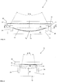
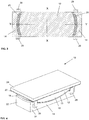
- the structural bearing 10 has a sliding body 12 with a base surface 16 and a convex, spherical segment-shaped curved sliding surface 17 and a receptacle 14 for the movable mounting of the slider 12.
- the receptacle 14 has a concave, spherical segment-shaped curved receiving surface 20 which surrounds the sliding surface 17 of the slider 12 at least partially.
- the receptacle 14 has four receiving side surface 21, 22, which is arranged so that they limit the receiving surface 20 so that each has a surface edge 13, with respect to the lowest point Ta of the concave receiving surface 20 one in her Course in the region of the receiving side surface 21; 22 variable height.
- the receptacle 14 has two pairs of opposing receiving side surfaces 21, 22, which are arranged symmetrically to the lowest point Ta of the concave receiving surface 20.
- the receptacle 14 also has a substantially cuboid shape with a rectangular planar base 19 of an opposite concave receiving surface 20 and four to the base 19 vertical side surfaces 21, 22. These are aligned with the slider side surfaces 18 of the slider 12.
- the curvature of this receiving surface 20 corresponds to the sliding surface 17 of the Gleitgropers.
- Thenac14 is presently made of steel and has a rectangular in plan view base 19. The opening angles of the receiving surfaces meet the European standard 1337-7.
- the slider 12 has the shape of a segment of a spherical cap with at least one slider side surface 18 having a variable height. Furthermore, the sliding body 12 has a substantially cuboid shape with a rectangular, flat base surface 16 and four perpendicular to the base surface 16, flat Gleit stresses side surfaces 18, wherein each two opposing side surfaces 18 symmetrical to the highest point Tg of the convexly curved sliding surface of the slider 12th are arranged.
- the slider 12 is presently made of metal and has a hard chrome-plated surface.
- the structural bearing 10 comprises a counter surface formed here in the form of a counter-plate 23.
- This counter-plate 23 faces the base 16 of the slider 12, whereby a floating mounting of the slider 12 on the counter-plate 23 can be realized.
- the counter-plate 23 is formed as an austenitic chromium-nickel-alloyed steel sheet and has a substantially rectangular shape.
- the mating surface can also be formed from a suitable surface finishing layer, in particular a hard chrome plating layer.
- the counter-plate 23 is in turn attached to a support plate 24.
- the support plate 24 is presently formed of metal and has a corresponding to the counter-plate 23 shape.
- the support plate 24 has a significantly higher material thickness than the counter-plate 23.
- Support plate 24 and counter-plate 23 are permanently connected to each other.
- the structural bearing 10 according to the invention according to the first embodiment each having a curved and flat sliding plates 25, 26.
- These slide plates 25, 26 serve as sliding partners for the counter-plate 23 and the sliding body 12 and are formed from one of the above-mentioned sliding materials.
- these non-illustrated lubrication pockets for a lubricating material are formed from one of the above-mentioned sliding materials.
- sliding plates 25, 26 are shear-resistant respectively attached to the concave receiving surface 20 of the receptacle 14 and to the flat base 16 of the slider 12.
- the sliding plates 25, 26 have a shape which corresponds to the receiving surface 20 or the base 16, but are less wide and long than these.
- the curved slide plate 26 accordingly has opening angles 2 ⁇ x and 2 ⁇ y, which are somewhat smaller than those of the receiving surface 20.
- the receiving surface 20 and the base 16 of the slider 12 have recesses 27, 28 in which the sliding plates are chambered in such a way that they protrude in accordance with the requirements of EN 1337-2 partially over each of the receiving surface 20 or the base 16.
- the sliding plates 25, 26 arranged shear-resistant in the recesses 27, 28.
- the building warehouse 10 has four stops 29.
- two stops 29 are arranged on the longitudinal receiving side surfaces 21 of the receptacle 14.
- a rotational movement of the slider 12 in the direction of the stops 29 is at least partially limited.
- the stops 29 have an L-shaped profile, so that respective stop regions 30 are spaced from the receiving side surfaces 21 of the receptacle 14. In this way, the structural bearing according to the first embodiment has an azimuthal play.
- the second embodiment of the structural bearing 31 according to the invention initially differs from the first in that it has a second counter-plate 36 and support plate 32, which are formed analogously to the first counter-plate 23 and support plate 24.
- This second counter-plate 36 faces the base 19 of the receptacle 14.
- the second support plate 32 is also formed of metal.
- two elongated guides 34 are arranged made of metal. These run in each case at the edge and parallel to the end faces 35 of the carrier 32.
- These guides 34 restrict the movement of the receptacle 14 to the second counter-plate 36, which is formed as a thin austenitic chromium-nickel-alloyed steel sheet. This steel sheet is bent in a U-shape, so that this fits perfectly between the Guides 34 on the support plate 32 can be arranged.
- Counter-plate 36 and stops 34 are welded to the support plate 32.
- the structural bearing 31 according to the second embodiment has a further sliding plate 37.
- This also consists of one of the above sliding materials, such as PTFE, UHMWPE, polyamide or the like.
- This is similar to the sliding plates 25, 26 fixedly mounted on the receptacle 14.
- the receptacle 14 also has lateral sliding contact surfaces 40 on its end faces 38 facing in the installation position 34. These are presently designed as thin strips of one of the already mentioned, suitable sliding materials. These are fastened by means of screwing in corresponding recesses on the end faces 38 such that the Gleitstrom vom 40 at least partially project laterally beyond the end faces 22 of the system 14.
- the guides 34 are arranged such that movement in the longitudinal direction of the carrier 32 is prevented, while a transverse movement parallel to the guides 34 is possible.
- the carrier plates 24, 32 also each have two stops 42, which are each arranged centrally on the longitudinal sides 43, 46 of the carrier plates 32, 24.
- stops 42 have similar to the stops 29 on the receptacle 14 on an L-shaped profile. Furthermore, these stops 42 also sliding bearing surfaces 44 which are formed here as a thin strip of a sliding material. These are fastened in a manner not shown in recesses of the stops 42, which face in the installation position of the receptacle 14 and the slider 12. By means of the Gleitstrom vom 44 excessive rubbing of the receptacle 14 is prevented at the stops 42.
- the stops 42 are formed here from metal.
- the Gleitstrom perennial 44 are spaced by means of the profile-shaped shape of the stops 42 of the longitudinal sides 43, 46 of the support plates 24, 32.
- the structural bearing 31 according to the second embodiment has azimuthal play and horizontal play.
Landscapes
- Engineering & Computer Science (AREA)
- Mechanical Engineering (AREA)
- Architecture (AREA)
- Civil Engineering (AREA)
- Structural Engineering (AREA)
- Physics & Mathematics (AREA)
- Electromagnetism (AREA)
- Bearings For Parts Moving Linearly (AREA)
- Buildings Adapted To Withstand Abnormal External Influences (AREA)
- Vibration Prevention Devices (AREA)
- Pivots And Pivotal Connections (AREA)
Claims (23)
- Appareil d'appui pour ouvrage d'art (10 ; 31), qui comporte un corps glissant (12) doté d'une surface de base (16) et d'une surface de glissement courbée de manière convexe en forme de calotte sphérique, ainsi qu'un logement (14) destiné à supporter de façon mobile le corps glissant (12), le logement (14) comportant une surface de logement (20) courbée de manière concave en forme de calotte sphérique et entourant au moins partiellement la surface de glissement (17) du corps glissant (12),
le logement (14) comportant au moins une surface latérale de logement (21 ; 22) qui est disposée de telle sorte qu'elle borde la surface de logement (20) de façon à ce que celle-ci ait un bord de surface (13) dont la hauteur, par rapport au point le plus bas (Ta) de la surface de logement (20) courbée de manière concave, est variable dans la zone de la surface latérale de logement (21 ; 22),
caractérisé en ce que
l'appareil d'appui pour ouvrage d'art (10 ; 31) comprend au moins une plaque de glissement plane (26 ; 37). - Appareil d'appui pour ouvrage d'art (10 ; 31) selon la revendication 1,
caractérisé en ce que
la plaque de glissement plane (26 ; 37) est agencée dans l'appareil d'appui de manière à être tournée vers la surface de base (19) du logement (14) et/ou vers la surface de base (16) du corps glissant (12), de sorte qu'un support flottant du logement (14) et/ou du corps glissant (12) peut être réalisé. - Appareil d'appui pour ouvrage d'art (10 ; 31) selon l'une quelconque des revendications 1 ou 2,
caractérisé en ce que
l'appareil d'appui (10 ; 31) comprend au moins une contreplaque plane (23 ; 26) pour la plaque de glissement plane (26 ; 37). - Appareil d'appui pour ouvrage d'art (10 ; 31) selon la revendication 3,
caractérisé en ce que
au moins une contre-plaque plane (23 ; 36) est maintenue dans une plaque de support (24 ; 32). - Appareil d'appui pour ouvrage d'art (10 ; 31) selon la revendication 4,
caractérisé en ce que
la plaque de support (24, 32) présente une forme sensiblement rectangulaire. - Appareil d'appui pour ouvrage d'art (10; 31) selon l'une quelconque des revendications précédentes,
caractérisé en ce que
le logement (14) comprend au moins deux surfaces latérales de logement (21 ; 22), de préférence quatre, qui sont disposées de sorte qu'elles bordent la surface de logement (20) de façon à ce que celle-ci ait un bord de surface (13) dont la hauteur, par rapport au point le plus bas (Ta) de la surface de logement courbée de manière concave (20), soit variable dans la zone des surfaces latérales de logement (21 ; 22). - Appareil d'appui pour ouvrage d'art (10 ; 31) selon la revendication 6,
caractérisé en ce que
au moins deux surfaces latérales de logement (21, 22) opposées sont disposées de manière symétrique par rapport au point le plus bas (Ta) de la surface de logement courbée de manière concave (20). - Appareil d'appui pour ouvrage d'art (10 ; 31) selon l'une quelconque des revendications 6 ou 7,
caractérisé en ce que
au moins deux surfaces latérales de logement (21 ; 22) opposées sont disposées de manière asymétrique par rapport au point le plus bas (Ta) de la surface de logement courbée de manière concave (20). - Appareil d'appui pour ouvrage d'art (10 ; 31) selon l'une quelconque des revendications précédentes,
caractérisé en ce que
le logement (14) comprend une surface de base (19) rectangulaire en vue en élévation. - Appareil d'appui pour ouvrage d'art (10; 31) selon l'une quelconque des revendications précédentes,
caractérisé en ce que
le corps glissant (12) présente la forme d'un segment d'une calotte sphérique comprenant au moins une surface latérale de corps glissant (18), qui possède une hauteur variable. - Appareil d'appui pour ouvrage d'art (10 ; 31) selon la revendication 10,
caractérisé en ce que
au moins deux surfaces latérales de corps glissant (18) opposées sont disposées de manière symétrique par rapport au point le plus haut (Tg) de la surface de glissement courbée de manière convexe (17) du corps glissant (12). - Appareil d'appui pour ouvrage d'art (10 ; 31) selon l'une quelconque des revendications 10 ou 11,
caractérisé en ce que
au moins deux surfaces latérales de corps glissant (18) opposées sont agencées de manière asymétrique par rapport au point le plus haut (Tg) de la surface de glissement courbée de manière convexe (17) du corps glissant (12). - Appareil d'appui pour ouvrage d'art (10 ; 31) selon l'une quelconque des revendications précédentes,
caractérisé en ce que
le corps glissant (12) comprend une surface de base (16) rectangulaire en vue en élévation. - Appareil d'appui pour ouvrage d'art (10 ; 31) selon l'une quelconque des revendications précédentes,
caractérisé en ce que
le corps glissant (12), en position de repos, est disposé dans l'appareil d'appui pour ouvrage d'art (10 ; 31) de sorte qu'au moins une surface latérale de corps glissant (18) est orientée sensiblement en alignement avec au moins une surface latérale de logement (21 ; 22). - Appareil d'appui pour ouvrage d'art (10; 31) selon l'une quelconque des revendications précédentes, caractérisé en ce que
le corps glissant (12) et/ou le logement (14) présentent une forme sensiblement parallélépipédique. - Appareil d'appui pour ouvrage d'art (10 ; 31) selon l'une quelconque des revendications précédentes,
caractérisé en ce que
au moins une surface latérale du corps glissant (12) et/ou du logement (14) est disposée perpendiculairement à la surface de base du corps glissant (12) et/ou de la surface de base du logement (14). - Appareil d'appui pour ouvrage d'art (10; 31) selon l'une quelconque des revendications précédentes, caractérisé en ce que
le corps glissant (12) et/ou le logement (14) sont conçus de sorte qu'ils satisfont les exigences de la norme EN 1337-7 en ce qui concerne l'angle d'ouverture admissible pour les calottes. - Appareil d'appui pour ouvrage d'art (10; 31) selon l'une quelconque des revendications précédentes, caractérisé en ce que
une plaque de glissement (25) courbée est disposée dans le logement. - Appareil d'appui pour ouvrage d'art (10 ; 31) selon l'une quelconque des revendications précédentes,
caractérisé en ce que
l'appareil d'appui pour ouvrage d'art (10 ; 31) comprend au moins une butée (29 ; 34 ; 42), de sorte qu'un mouvement en rotation ou en translation du logement (14), du corps glissant (12) et/ou d'au moins une plaque de support (24 ; 32) peut être au moins partiellement limité. - Appareil d'appui pour ouvrage d'art (10 ; 31) selon la revendication 19,
caractérisé en ce que
une butée (29 ; 42) est disposée sur la plaque de support (24 ; 32) et/ou sur le logement (14). - Appareil d'appui pour ouvrage d'art (10 ; 31) selon l'une quelconque des revendications 19 ou 20, caractérisé en ce que
la butée (29 ; 42) est disposée de sorte que l'appareil d'appui pour ouvrage d'art (10 ; 31) présente un jeu horizontal et/ou azimutal. - Appareil d'appui pour ouvrage d'art (10 ; 31) selon l'une quelconque des revendications 19 à 21, caractérisé en ce que
la butée (29, 42) présente un profil en forme de L. - Appareil d'appui pour ouvrage d'art (10 ; 31) selon l'une quelconque des revendications 19 à 22,
caractérisé en ce que
la butée (42) comprend une surface de butée de glissement (44).
Applications Claiming Priority (2)
| Application Number | Priority Date | Filing Date | Title |
|---|---|---|---|
| DE102013104064.0A DE102013104064A1 (de) | 2013-04-22 | 2013-04-22 | Bauwerkslager |
| PCT/EP2014/056253 WO2014173621A1 (fr) | 2013-04-22 | 2014-03-28 | Appareil d'appui pour ouvrage d'art |
Publications (2)
| Publication Number | Publication Date |
|---|---|
| EP2989253A1 EP2989253A1 (fr) | 2016-03-02 |
| EP2989253B1 true EP2989253B1 (fr) | 2017-05-10 |
Family
ID=50391176
Family Applications (1)
| Application Number | Title | Priority Date | Filing Date |
|---|---|---|---|
| EP14713830.9A Active EP2989253B1 (fr) | 2013-04-22 | 2014-03-28 | Appui structurel |
Country Status (4)
| Country | Link |
|---|---|
| EP (1) | EP2989253B1 (fr) |
| DE (1) | DE102013104064A1 (fr) |
| RU (1) | RU2665772C2 (fr) |
| WO (1) | WO2014173621A1 (fr) |
Cited By (1)
| Publication number | Priority date | Publication date | Assignee | Title |
|---|---|---|---|---|
| DE102020106688A1 (de) | 2020-03-11 | 2021-09-16 | Mageba Holding Ag | Bauwerk mit einem tragendenden ersten Bauwerksteil und einem über ein Bauwerkslager auf diesem abgestützten zweiten Bauwerksteil |
Families Citing this family (4)
| Publication number | Priority date | Publication date | Assignee | Title |
|---|---|---|---|---|
| CN104746424A (zh) * | 2015-04-02 | 2015-07-01 | 衡水中铁建工程橡胶有限责任公司 | 一种钢阻尼球型支座 |
| CN105545057B (zh) * | 2016-01-27 | 2017-12-15 | 云南昆钢钢结构股份有限公司 | 具有抗提离功能的摩擦滑移摆隔震支座 |
| US11421435B2 (en) * | 2018-12-12 | 2022-08-23 | Universidad Catolica De La Santisima Concepcion | Kinematic seismic isolation device |
| CN110241930A (zh) * | 2019-07-15 | 2019-09-17 | 无锡安特斯密减隔震科技有限公司 | 一种摩擦摆支座 |
Citations (1)
| Publication number | Priority date | Publication date | Assignee | Title |
|---|---|---|---|---|
| EP0943736A2 (fr) | 1998-03-17 | 1999-09-22 | Bouwdienst Rijkswaterstaat | Appui |
Family Cites Families (9)
| Publication number | Priority date | Publication date | Assignee | Title |
|---|---|---|---|---|
| FR1164759A (fr) * | 1957-01-15 | 1958-10-14 | Stup Procedes Freyssinet | Dispositif d'appui à plusieurs degrés de liberté applicable en particulier aux ouvrages d'art |
| FR1398214A (fr) * | 1964-05-06 | 1965-05-07 | Glacier Co Ltd | Appui capable de supporter des charges verticales |
| GB1042397A (en) * | 1964-08-11 | 1966-09-14 | P S C Equipment Ltd | Improvements in bearings for bridges and like structures |
| DE2829309B2 (de) * | 1978-07-04 | 1980-08-07 | Glacier Gmbh Deva Werke | Verfahren zum Auskleiden der Konkav gewölbten Oberseite der Unterplatte eines Kippbewegungen eines Brückenüberbaus o.dgl. ermöglichenden Lagers und nach diesem Verfahren ausgekleidetes Lager |
| US20020012482A1 (en) * | 1996-03-12 | 2002-01-31 | Pridgeon David Kenneth | Bearings |
| DE19710710C2 (de) * | 1997-03-14 | 2002-08-01 | Maurer Friedrich Soehne | Lager zur Aufnahme von Lagerkräften zwischen Bauteilen |
| RU2160807C1 (ru) * | 2000-05-29 | 2000-12-20 | Открытое акционерное общество "Мостотрест" | Опорная часть моста |
| WO2009034585A1 (fr) * | 2007-09-11 | 2009-03-19 | Alga S.P.A. | Isolateur sismique à pendule coulissant |
| RU99015U1 (ru) * | 2010-03-04 | 2010-11-10 | ООО "Деформационные швы и опорные части" | Опорная часть моста |
-
2013
- 2013-04-22 DE DE102013104064.0A patent/DE102013104064A1/de not_active Withdrawn
-
2014
- 2014-03-28 RU RU2015147440A patent/RU2665772C2/ru active
- 2014-03-28 EP EP14713830.9A patent/EP2989253B1/fr active Active
- 2014-03-28 WO PCT/EP2014/056253 patent/WO2014173621A1/fr not_active Ceased
Patent Citations (1)
| Publication number | Priority date | Publication date | Assignee | Title |
|---|---|---|---|---|
| EP0943736A2 (fr) | 1998-03-17 | 1999-09-22 | Bouwdienst Rijkswaterstaat | Appui |
Non-Patent Citations (2)
| Title |
|---|
| "Lager im Bauwesen - Teil 7: Kalotten- und Zylinderlager mit PTFE", DEUTSCHE FASSUNG EN 1337-7:2004, August 2004 (2004-08-01), XP055465756 |
| "Lager im Bauwesen-Teil 1: Allgemeine Regelungen", DIN EN 1337-1:2001-02, February 2001 (2001-02-01), XP055465741 |
Cited By (2)
| Publication number | Priority date | Publication date | Assignee | Title |
|---|---|---|---|---|
| DE102020106688A1 (de) | 2020-03-11 | 2021-09-16 | Mageba Holding Ag | Bauwerk mit einem tragendenden ersten Bauwerksteil und einem über ein Bauwerkslager auf diesem abgestützten zweiten Bauwerksteil |
| DE102020106688B4 (de) | 2020-03-11 | 2026-07-23 | Mageba Services & Technology Ag | Bauwerk mit einem tragendenden ersten Bauwerksteil und einem über ein Bauwerkslager auf diesem abgestützten zweiten Bauwerksteil |
Also Published As
| Publication number | Publication date |
|---|---|
| RU2665772C2 (ru) | 2018-09-04 |
| EP2989253A1 (fr) | 2016-03-02 |
| WO2014173621A1 (fr) | 2014-10-30 |
| RU2015147440A (ru) | 2017-05-26 |
| DE102013104064A1 (de) | 2014-10-23 |
Similar Documents
| Publication | Publication Date | Title |
|---|---|---|
| DE69217871T2 (de) | Wälzlager für Linearbewegungen | |
| EP3134283B1 (fr) | Joint d'étanchéité de carosserie de véhicule avec bandeau enjoliveur | |
| WO2014173621A1 (fr) | Appareil d'appui pour ouvrage d'art | |
| DE2642227B1 (de) | Klemmelement | |
| DD302032A7 (de) | Ausbildung einer schmiermittelversorgung bei einem waelzlager fuer linearbewegungen | |
| DE3227902C2 (de) | Linearkugellagereinheit | |
| EP2426050B1 (fr) | Elément de coussinet d'un palier de gouvernail | |
| DE102013216880A1 (de) | Linearbewegungsvorrichtung | |
| EP3680419B1 (fr) | Dispositif de recouvrement de joint de dilatation | |
| AT413829B (de) | Vorrichtung zum überbrücken von dehnfugen in fahrbahnen | |
| EP1430232B1 (fr) | Frein a disque destine notamment a un vehicule utilitaire | |
| EP2232091B1 (fr) | Cage pour corps de roulement | |
| AT524788A4 (de) | Verriegelungselement | |
| DE102010034908B4 (de) | Skateboard-Truck | |
| DE102013215842A1 (de) | Linearantrieb | |
| DE2349432C3 (de) | Dichtung für ein Loslager für den Tragzapfen eines Konverters | |
| EP0706470B1 (fr) | Palier lisse, notamment pour le panneau de cale a bord de navires | |
| EP1743826A1 (fr) | Mécanisme de direction de véhicule automobile | |
| EP0338124A2 (fr) | Dispositif de pontage de joint de tablier | |
| DE102020106907A1 (de) | Schwenkwiegenlagerung und Verfahren zur Herstellung einer Synchronisationsvorrichtung einer Schwenkwiegenlagerung | |
| DE102008028110C5 (de) | Abstreiferanordnung | |
| DE202016107323U1 (de) | Laufrollenführungssystem für die Bewegung von Maschinen und Maschinenteilen | |
| DE202008010087U1 (de) | Abstreifer | |
| DE202007011599U1 (de) | Tragstruktur für Leichtbauelemente | |
| DE1575462A1 (de) | Gleitlager |
Legal Events
| Date | Code | Title | Description |
|---|---|---|---|
| PUAI | Public reference made under article 153(3) epc to a published international application that has entered the european phase |
Free format text: ORIGINAL CODE: 0009012 |
|
| 17P | Request for examination filed |
Effective date: 20151012 |
|
| AK | Designated contracting states |
Kind code of ref document: A1 Designated state(s): AL AT BE BG CH CY CZ DE DK EE ES FI FR GB GR HR HU IE IS IT LI LT LU LV MC MK MT NL NO PL PT RO RS SE SI SK SM TR |
|
| AX | Request for extension of the european patent |
Extension state: BA ME |
|
| DAX | Request for extension of the european patent (deleted) | ||
| GRAP | Despatch of communication of intention to grant a patent |
Free format text: ORIGINAL CODE: EPIDOSNIGR1 |
|
| STAA | Information on the status of an ep patent application or granted ep patent |
Free format text: STATUS: GRANT OF PATENT IS INTENDED |
|
| INTG | Intention to grant announced |
Effective date: 20161122 |
|
| GRAS | Grant fee paid |
Free format text: ORIGINAL CODE: EPIDOSNIGR3 |
|
| GRAA | (expected) grant |
Free format text: ORIGINAL CODE: 0009210 |
|
| STAA | Information on the status of an ep patent application or granted ep patent |
Free format text: STATUS: THE PATENT HAS BEEN GRANTED |
|
| AK | Designated contracting states |
Kind code of ref document: B1 Designated state(s): AL AT BE BG CH CY CZ DE DK EE ES FI FR GB GR HR HU IE IS IT LI LT LU LV MC MK MT NL NO PL PT RO RS SE SI SK SM TR |
|
| REG | Reference to a national code |
Ref country code: GB Ref legal event code: FG4D Free format text: NOT ENGLISH |
|
| REG | Reference to a national code |
Ref country code: AT Ref legal event code: REF Ref document number: 892454 Country of ref document: AT Kind code of ref document: T Effective date: 20170515 Ref country code: CH Ref legal event code: EP |
|
| REG | Reference to a national code |
Ref country code: IE Ref legal event code: FG4D Free format text: LANGUAGE OF EP DOCUMENT: GERMAN |
|
| REG | Reference to a national code |
Ref country code: DE Ref legal event code: R096 Ref document number: 502014003789 Country of ref document: DE |
|
| REG | Reference to a national code |
Ref country code: CH Ref legal event code: NV Representative=s name: TROESCH SCHEIDEGGER WERNER AG, CH |
|
| REG | Reference to a national code |
Ref country code: NL Ref legal event code: MP Effective date: 20170510 |
|
| REG | Reference to a national code |
Ref country code: LT Ref legal event code: MG4D |
|
| PG25 | Lapsed in a contracting state [announced via postgrant information from national office to epo] |
Ref country code: LT Free format text: LAPSE BECAUSE OF FAILURE TO SUBMIT A TRANSLATION OF THE DESCRIPTION OR TO PAY THE FEE WITHIN THE PRESCRIBED TIME-LIMIT Effective date: 20170510 Ref country code: HR Free format text: LAPSE BECAUSE OF FAILURE TO SUBMIT A TRANSLATION OF THE DESCRIPTION OR TO PAY THE FEE WITHIN THE PRESCRIBED TIME-LIMIT Effective date: 20170510 Ref country code: GR Free format text: LAPSE BECAUSE OF FAILURE TO SUBMIT A TRANSLATION OF THE DESCRIPTION OR TO PAY THE FEE WITHIN THE PRESCRIBED TIME-LIMIT Effective date: 20170811 Ref country code: NO Free format text: LAPSE BECAUSE OF FAILURE TO SUBMIT A TRANSLATION OF THE DESCRIPTION OR TO PAY THE FEE WITHIN THE PRESCRIBED TIME-LIMIT Effective date: 20170810 Ref country code: ES Free format text: LAPSE BECAUSE OF FAILURE TO SUBMIT A TRANSLATION OF THE DESCRIPTION OR TO PAY THE FEE WITHIN THE PRESCRIBED TIME-LIMIT Effective date: 20170510 Ref country code: FI Free format text: LAPSE BECAUSE OF FAILURE TO SUBMIT A TRANSLATION OF THE DESCRIPTION OR TO PAY THE FEE WITHIN THE PRESCRIBED TIME-LIMIT Effective date: 20170510 |
|
| PG25 | Lapsed in a contracting state [announced via postgrant information from national office to epo] |
Ref country code: RS Free format text: LAPSE BECAUSE OF FAILURE TO SUBMIT A TRANSLATION OF THE DESCRIPTION OR TO PAY THE FEE WITHIN THE PRESCRIBED TIME-LIMIT Effective date: 20170510 Ref country code: NL Free format text: LAPSE BECAUSE OF FAILURE TO SUBMIT A TRANSLATION OF THE DESCRIPTION OR TO PAY THE FEE WITHIN THE PRESCRIBED TIME-LIMIT Effective date: 20170510 Ref country code: PL Free format text: LAPSE BECAUSE OF FAILURE TO SUBMIT A TRANSLATION OF THE DESCRIPTION OR TO PAY THE FEE WITHIN THE PRESCRIBED TIME-LIMIT Effective date: 20170510 Ref country code: BG Free format text: LAPSE BECAUSE OF FAILURE TO SUBMIT A TRANSLATION OF THE DESCRIPTION OR TO PAY THE FEE WITHIN THE PRESCRIBED TIME-LIMIT Effective date: 20170810 Ref country code: SE Free format text: LAPSE BECAUSE OF FAILURE TO SUBMIT A TRANSLATION OF THE DESCRIPTION OR TO PAY THE FEE WITHIN THE PRESCRIBED TIME-LIMIT Effective date: 20170510 Ref country code: IS Free format text: LAPSE BECAUSE OF FAILURE TO SUBMIT A TRANSLATION OF THE DESCRIPTION OR TO PAY THE FEE WITHIN THE PRESCRIBED TIME-LIMIT Effective date: 20170910 Ref country code: LV Free format text: LAPSE BECAUSE OF FAILURE TO SUBMIT A TRANSLATION OF THE DESCRIPTION OR TO PAY THE FEE WITHIN THE PRESCRIBED TIME-LIMIT Effective date: 20170510 |
|
| PG25 | Lapsed in a contracting state [announced via postgrant information from national office to epo] |
Ref country code: RO Free format text: LAPSE BECAUSE OF FAILURE TO SUBMIT A TRANSLATION OF THE DESCRIPTION OR TO PAY THE FEE WITHIN THE PRESCRIBED TIME-LIMIT Effective date: 20170510 Ref country code: SK Free format text: LAPSE BECAUSE OF FAILURE TO SUBMIT A TRANSLATION OF THE DESCRIPTION OR TO PAY THE FEE WITHIN THE PRESCRIBED TIME-LIMIT Effective date: 20170510 Ref country code: EE Free format text: LAPSE BECAUSE OF FAILURE TO SUBMIT A TRANSLATION OF THE DESCRIPTION OR TO PAY THE FEE WITHIN THE PRESCRIBED TIME-LIMIT Effective date: 20170510 Ref country code: CZ Free format text: LAPSE BECAUSE OF FAILURE TO SUBMIT A TRANSLATION OF THE DESCRIPTION OR TO PAY THE FEE WITHIN THE PRESCRIBED TIME-LIMIT Effective date: 20170510 Ref country code: DK Free format text: LAPSE BECAUSE OF FAILURE TO SUBMIT A TRANSLATION OF THE DESCRIPTION OR TO PAY THE FEE WITHIN THE PRESCRIBED TIME-LIMIT Effective date: 20170510 |
|
| REG | Reference to a national code |
Ref country code: DE Ref legal event code: R026 Ref document number: 502014003789 Country of ref document: DE |
|
| PLBI | Opposition filed |
Free format text: ORIGINAL CODE: 0009260 |
|
| PG25 | Lapsed in a contracting state [announced via postgrant information from national office to epo] |
Ref country code: SM Free format text: LAPSE BECAUSE OF FAILURE TO SUBMIT A TRANSLATION OF THE DESCRIPTION OR TO PAY THE FEE WITHIN THE PRESCRIBED TIME-LIMIT Effective date: 20170510 |
|
| 26 | Opposition filed |
Opponent name: MAGEBA S.A. Effective date: 20180210 |
|
| REG | Reference to a national code |
Ref country code: FR Ref legal event code: PLFP Year of fee payment: 5 |
|
| PG25 | Lapsed in a contracting state [announced via postgrant information from national office to epo] |
Ref country code: SI Free format text: LAPSE BECAUSE OF FAILURE TO SUBMIT A TRANSLATION OF THE DESCRIPTION OR TO PAY THE FEE WITHIN THE PRESCRIBED TIME-LIMIT Effective date: 20170510 |
|
| PG25 | Lapsed in a contracting state [announced via postgrant information from national office to epo] |
Ref country code: MT Free format text: LAPSE BECAUSE OF FAILURE TO SUBMIT A TRANSLATION OF THE DESCRIPTION OR TO PAY THE FEE WITHIN THE PRESCRIBED TIME-LIMIT Effective date: 20170510 |
|
| GBPC | Gb: european patent ceased through non-payment of renewal fee |
Effective date: 20180328 |
|
| PG25 | Lapsed in a contracting state [announced via postgrant information from national office to epo] |
Ref country code: MC Free format text: LAPSE BECAUSE OF FAILURE TO SUBMIT A TRANSLATION OF THE DESCRIPTION OR TO PAY THE FEE WITHIN THE PRESCRIBED TIME-LIMIT Effective date: 20170510 |
|
| REG | Reference to a national code |
Ref country code: BE Ref legal event code: MM Effective date: 20180331 |
|
| REG | Reference to a national code |
Ref country code: IE Ref legal event code: MM4A |
|
| PG25 | Lapsed in a contracting state [announced via postgrant information from national office to epo] |
Ref country code: LU Free format text: LAPSE BECAUSE OF NON-PAYMENT OF DUE FEES Effective date: 20180328 |
|
| PG25 | Lapsed in a contracting state [announced via postgrant information from national office to epo] |
Ref country code: IE Free format text: LAPSE BECAUSE OF NON-PAYMENT OF DUE FEES Effective date: 20180328 |
|
| PG25 | Lapsed in a contracting state [announced via postgrant information from national office to epo] |
Ref country code: BE Free format text: LAPSE BECAUSE OF NON-PAYMENT OF DUE FEES Effective date: 20180331 Ref country code: GB Free format text: LAPSE BECAUSE OF NON-PAYMENT OF DUE FEES Effective date: 20180328 |
|
| APBM | Appeal reference recorded |
Free format text: ORIGINAL CODE: EPIDOSNREFNO |
|
| APAH | Appeal reference modified |
Free format text: ORIGINAL CODE: EPIDOSCREFNO |
|
| PG25 | Lapsed in a contracting state [announced via postgrant information from national office to epo] |
Ref country code: PT Free format text: LAPSE BECAUSE OF FAILURE TO SUBMIT A TRANSLATION OF THE DESCRIPTION OR TO PAY THE FEE WITHIN THE PRESCRIBED TIME-LIMIT Effective date: 20170510 |
|
| PG25 | Lapsed in a contracting state [announced via postgrant information from national office to epo] |
Ref country code: HU Free format text: LAPSE BECAUSE OF FAILURE TO SUBMIT A TRANSLATION OF THE DESCRIPTION OR TO PAY THE FEE WITHIN THE PRESCRIBED TIME-LIMIT; INVALID AB INITIO Effective date: 20140328 Ref country code: CY Free format text: LAPSE BECAUSE OF FAILURE TO SUBMIT A TRANSLATION OF THE DESCRIPTION OR TO PAY THE FEE WITHIN THE PRESCRIBED TIME-LIMIT Effective date: 20170510 Ref country code: MK Free format text: LAPSE BECAUSE OF NON-PAYMENT OF DUE FEES Effective date: 20170510 |
|
| PG25 | Lapsed in a contracting state [announced via postgrant information from national office to epo] |
Ref country code: AL Free format text: LAPSE BECAUSE OF FAILURE TO SUBMIT A TRANSLATION OF THE DESCRIPTION OR TO PAY THE FEE WITHIN THE PRESCRIBED TIME-LIMIT Effective date: 20170510 |
|
| PLBG | Opposition deemed not to have been filed |
Free format text: ORIGINAL CODE: 0009274 |
|
| 26D | Opposition deemed not to have been filed |
Opponent name: MAGEBA S.A. Effective date: 20210715 |
|
| REG | Reference to a national code |
Ref country code: CH Ref legal event code: U11 Free format text: ST27 STATUS EVENT CODE: U-0-0-U10-U11 (AS PROVIDED BY THE NATIONAL OFFICE) Effective date: 20260401 |
|
| PGFP | Annual fee paid to national office [announced via postgrant information from national office to epo] |
Ref country code: DE Payment date: 20260320 Year of fee payment: 13 |
|
| PGFP | Annual fee paid to national office [announced via postgrant information from national office to epo] |
Ref country code: AT Payment date: 20260319 Year of fee payment: 13 |
|
| PGFP | Annual fee paid to national office [announced via postgrant information from national office to epo] |
Ref country code: FR Payment date: 20260324 Year of fee payment: 13 |
|
| PGFP | Annual fee paid to national office [announced via postgrant information from national office to epo] |
Ref country code: TR Payment date: 20260326 Year of fee payment: 13 |
|
| PGFP | Annual fee paid to national office [announced via postgrant information from national office to epo] |
Ref country code: IT Payment date: 20260331 Year of fee payment: 13 |
|
| PGFP | Annual fee paid to national office [announced via postgrant information from national office to epo] |
Ref country code: CH Payment date: 20260401 Year of fee payment: 13 |