EP2989314B1 - Ausrichtbares raketenmotorsystem - Google Patents
Ausrichtbares raketenmotorsystem Download PDFInfo
- Publication number
- EP2989314B1 EP2989314B1 EP14725212.6A EP14725212A EP2989314B1 EP 2989314 B1 EP2989314 B1 EP 2989314B1 EP 14725212 A EP14725212 A EP 14725212A EP 2989314 B1 EP2989314 B1 EP 2989314B1
- Authority
- EP
- European Patent Office
- Prior art keywords
- base
- nozzle
- rocket motor
- articulated
- support structure
- Prior art date
- Legal status (The legal status is an assumption and is not a legal conclusion. Google has not performed a legal analysis and makes no representation as to the accuracy of the status listed.)
- Active
Links
Images
Classifications
-
- F—MECHANICAL ENGINEERING; LIGHTING; HEATING; WEAPONS; BLASTING
- F02—COMBUSTION ENGINES; HOT-GAS OR COMBUSTION-PRODUCT ENGINE PLANTS
- F02K—JET-PROPULSION PLANTS
- F02K9/00—Rocket-engine plants, i.e. plants carrying both fuel and oxidant therefor; Control thereof
- F02K9/42—Rocket-engine plants, i.e. plants carrying both fuel and oxidant therefor; Control thereof using liquid or gaseous propellants
- F02K9/44—Feeding propellants
- F02K9/56—Control
-
- F—MECHANICAL ENGINEERING; LIGHTING; HEATING; WEAPONS; BLASTING
- F02—COMBUSTION ENGINES; HOT-GAS OR COMBUSTION-PRODUCT ENGINE PLANTS
- F02K—JET-PROPULSION PLANTS
- F02K9/00—Rocket-engine plants, i.e. plants carrying both fuel and oxidant therefor; Control thereof
- F02K9/80—Rocket-engine plants, i.e. plants carrying both fuel and oxidant therefor; Control thereof characterised by thrust or thrust vector control
-
- F—MECHANICAL ENGINEERING; LIGHTING; HEATING; WEAPONS; BLASTING
- F02—COMBUSTION ENGINES; HOT-GAS OR COMBUSTION-PRODUCT ENGINE PLANTS
- F02K—JET-PROPULSION PLANTS
- F02K9/00—Rocket-engine plants, i.e. plants carrying both fuel and oxidant therefor; Control thereof
- F02K9/80—Rocket-engine plants, i.e. plants carrying both fuel and oxidant therefor; Control thereof characterised by thrust or thrust vector control
- F02K9/805—Rocket-engine plants, i.e. plants carrying both fuel and oxidant therefor; Control thereof characterised by thrust or thrust vector control servo-mechanisms or control devices therefor
-
- F—MECHANICAL ENGINEERING; LIGHTING; HEATING; WEAPONS; BLASTING
- F02—COMBUSTION ENGINES; HOT-GAS OR COMBUSTION-PRODUCT ENGINE PLANTS
- F02K—JET-PROPULSION PLANTS
- F02K9/00—Rocket-engine plants, i.e. plants carrying both fuel and oxidant therefor; Control thereof
- F02K9/80—Rocket-engine plants, i.e. plants carrying both fuel and oxidant therefor; Control thereof characterised by thrust or thrust vector control
- F02K9/84—Rocket-engine plants, i.e. plants carrying both fuel and oxidant therefor; Control thereof characterised by thrust or thrust vector control using movable nozzles
-
- F—MECHANICAL ENGINEERING; LIGHTING; HEATING; WEAPONS; BLASTING
- F05—INDEXING SCHEMES RELATING TO ENGINES OR PUMPS IN VARIOUS SUBCLASSES OF CLASSES F01-F04
- F05B—INDEXING SCHEME RELATING TO WIND, SPRING, WEIGHT, INERTIA OR LIKE MOTORS, TO MACHINES OR ENGINES FOR LIQUIDS COVERED BY SUBCLASSES F03B, F03D AND F03G
- F05B2240/00—Components
- F05B2240/90—Mounting on supporting structures or systems
- F05B2240/91—Mounting on supporting structures or systems on a stationary structure
- F05B2240/912—Mounting on supporting structures or systems on a stationary structure on a tower
- F05B2240/9121—Mounting on supporting structures or systems on a stationary structure on a tower on a lattice tower
-
- F—MECHANICAL ENGINEERING; LIGHTING; HEATING; WEAPONS; BLASTING
- F05—INDEXING SCHEMES RELATING TO ENGINES OR PUMPS IN VARIOUS SUBCLASSES OF CLASSES F01-F04
- F05B—INDEXING SCHEME RELATING TO WIND, SPRING, WEIGHT, INERTIA OR LIKE MOTORS, TO MACHINES OR ENGINES FOR LIQUIDS COVERED BY SUBCLASSES F03B, F03D AND F03G
- F05B2250/00—Geometry
- F05B2250/40—Movement of component
- F05B2250/43—Movement of component with three degrees of freedom
Definitions
- the present invention relates to a steerable rocket engine system for an air vehicle.
- this invention is particularly suitable to be implemented for a space airplane, that is to say an aircraft which is equipped, at the same time, with aerobic propulsion means, such as turbine engines, and with means anaerobic propulsion system, such as a rocket engine, which is capable of taking off from the ground in the usual manner for an airplane, reaching an altitude of at least one hundred kilometers, flying at a transonic or even supersonic speed, and then to also land in a usual way for an airplane.
- aerobic propulsion means such as turbine engines
- anaerobic propulsion system such as a rocket engine
- a rocket engine comprises a combustion chamber and a nozzle connected by a nozzle neck and that, in order to guide an aerial vehicle equipped with a rocket engine in flight, it is advantageous to control said engine rocket.
- the end of the combustion chamber opposite to the nozzle neck is articulated, for example to the gimbal, on the structure of the aerial vehicle, and actuating means, such as jacks, are provided. to pivot said rocket motor relative to this articulated end of the combustion chamber.
- This method has the disadvantage that, the nozzle ejection orifice being separated from said articulated end of the combustion chamber by the entire length of the rocket motor, the displacement of said gas ejection orifice. of the nozzle is transversely important. As a result, the cowling of the aerial vehicle enveloping the rocket engine must have a large diameter to allow the transverse clearance of the nozzle ejection orifice of the nozzle.
- this large cowling is a source of high aerodynamic drag affecting the performance of said air vehicle.
- the present invention aims to overcome these disadvantages.
- the transverse clearance of the gas ejection orifice of the nozzle is reduced, since its swing radius is also reduced and the center of said orifice remains in the vicinity of the reference axis.
- the rocket engine cowling can therefore have a smaller diameter and generate only lower aerodynamic drag.
- said hollow deformable support structure is formed by a lattice of articulated bars and said first actuating means are jacks articulated to at least one articulated bar of said lattice.
- the hollow deformable base structure can be formed by a lattice of articulated bars and said second actuating means can be jacks articulated to at least one articulated bar of the latter lattice.
- said first actuating means for the deformation of said support structure rest on said intermediate frame.
- Said tilting means may further comprise a base frame for the assembly of the lattice of said base structure on the overhead vehicle, the lattice bars of said base structure being hinged to said base frame around such seconds axes of rotation orthogonal to said second direction of deformation.
- said second actuating means for the deformation of said basic structure rest on said base frame.
- Said tilting means may comprise an end plate for attaching said rocket motor to said support structure, the bars of said support structure being articulated on said end plate about such axes of rotation orthogonal to said first direction deformation.
- the present invention also relates to an aerial vehicle, in particular a space airplane, comprising a steerable rocket engine system as specified above.
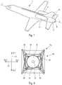
- the space airplane 1, according to the present invention and shown on the figure 1 has only one floor and is capable of performing transonic and / or supersonic flights.
- This space plane 1, of longitudinal axis LL, comprises two lateral turboshaft engines 2 and 3 and a rocket engine 4, disposed at the rear of said space airplane inside a base cowling 5, provided with an orifice 6 gas outlet.
- rocket engine 4 comprises a combustion chamber 7 and a nozzle 8 connected by a nozzle neck 9.
- the nozzle 8 comprises a gas ejection orifice 10 disposed opposite the outlet orifice 6 of the base cowling 5 (shown schematically in dashed outline). mixed on Figures 4 to 7 ).
- the rocket motor 4 is mounted (inside the base casing 5) on tilting means 11 able to deform in both directions 12.1 and 12.2 and 13.1 and 13.2 of each of two orthogonal deformation directions 12 and 13
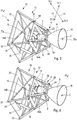
- the tilting means 11 comprise, on the one hand, a truncated-pyramidal frame 14 in lattice of articulated bars and, on the other hand, cylinders 15 and 16.
- the truncal-pyramidal frame 14 comprises a trunk-pyramidal support structure 14A carrying the rocket motor 4 by its small base and a basic truncated-pyramidal structure 14B carrying the trunk-pyramidal support structure 14A by its small base.
- the large base of the truncated-pyramidal structure 14A is connected to the small base of the truncated-pyramidal structure 14B thanks to an intermediate frame 17, to which the articulated bars 18 of the base structure 14B are articulated around axes 19 orthogonal to the deformation direction 13 and the articulated bars 20 of the support structure 14A are articulated about axes 21 orthogonal to the deformation direction 12.
- the truncated-pyramidal frame 14 further comprises, on the side of the large base of the structure 14B, a base frame 22 for connecting said frame to the structure of the space plane 1.
- the articulated bars 18 of the structure of base 14B are articulated to the base frame 22 about axes 23 orthogonal to the deformation direction 13.
- the cylinder 16 is articulated both on the base frame 22 on which it bears and on an articulated bar 18, so to be able to tilt the truncated-pyramidal structure 4B in both directions 13.1 and 13.2 of the deformation direction 13, by rotation about the axes 19 and 23 orthogonal to the latter direction of deformation.
- the support structure 14A On the side of its small base opposite to the base structure 14B, the support structure 14A carries, rigidly secured to the rocket motor 4.
- this small base is embodied by an end plate 24, of which said rocket engine is made integral by the part of the nozzle 8 adjacent to the nozzle neck 9, so that the combustion chamber 7 is inside the frame 14.
- the articulated bars 20 of the support structure 14A are articulated to the end plate 24 about axes 25 orthogonal to said deformation direction 12.
- the cylinder 15 is articulated both on the intermediate frame 17 on which it bears and on an articulated bar 20, so as to able to tilt the truncated-pyramidal structure 4A in both directions 12.1 and 12.2 of the deformation direction 12 by rotation about the axes 21 and 25 orthogonal to the latter direction of tilting.
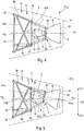
- a neutral orientation position P o serving as a reference position (see figures 2 , 4 and 5 )
- the axis of the rocket motor 4 occupies a position m o - m o which is orthogonal to the gas ejection orifice 10 of the nozzle 8 and passes through the center C of said orifice.
- This position m o - m o serves as a reference axis with respect to which the rocket motor 4 switches.
- the jack 15 deforms the truncated-pyramidal support structure 14A in one or the other direction 12.1, 12.2 of the deformation direction 12.
- Such deformations of the support structure 14A cause tilting of the end plate 24, so that the rocket motor 4 takes tilted positions P 1 in the directions 12.1, 12.2 of the direction 12, in which its axis takes positions m 12 - m 12 inclined relative at the reference axis m o - m o .
- the combustion chamber 7 and the nozzle 8 swing in opposite directions because the fixed motor 4 is made integral with the end plate 24 by the part of the nozzle 8 adjacent to the nozzle neck 9.
- the center C of the gas ejection orifice of the nozzle 10 can, in these positions P 1 tilted in the deformation direction 12, remain in the vicinity of the reference axis m o - m o , if not on this one.
- the displacement of the nozzle 10 in the deformation direction 12 may therefore be small.
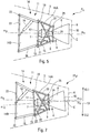
- the jack 16 deforms the truncated-pyramidal base structure 14B in either direction 13.1, 13.2 of the deformation direction 13.
- Such deformations of the basic structure 14B cause tilting of the intermediate plate 17, so that the rocket motor 4 takes tilted positions P 2 in the direction 13.1, 13.2 of the deformation direction 13, in which its axis takes positions m 13 - m 13 inclined relative to the reference axis m o - m o .
- the combustion chamber 7 and the nozzle 8 also swing in the opposite direction because the fixed motor 4 is made integral with the end plate 24 by the part of the nozzle 8 adjacent to the nozzle neck 9.
- the center C of the gas ejection orifice of the nozzle 10 can, in these positions P 2 pivoted in the deformation direction 13, remain at near the reference axis m o - m o , except on this one.
- the displacement of the nozzle 10 in the deformation direction 13 may therefore be small.
- the jacks 15 and 16 can act simultaneously to give the rocket motor 4 P 3 positions, tilted both in the deformation direction 12 and in the deformation direction 13.
Landscapes
- Engineering & Computer Science (AREA)
- Chemical & Material Sciences (AREA)
- Combustion & Propulsion (AREA)
- Mechanical Engineering (AREA)
- General Engineering & Computer Science (AREA)
- Toys (AREA)
- Testing Of Engines (AREA)
- Aerodynamic Tests, Hydrodynamic Tests, Wind Tunnels, And Water Tanks (AREA)
Claims (11)
- Lenkbares Raketentriebwerksystem fur Luftfahrzeug, wobei das Raketentriebwerk (4) eine Brennkammer (7) und eine Düse (8) aufweist, die durch einen Hals der Düse (9) verbunden sind, und wobei das System ermoglicht, das Raketentriebwerk (4) relativ zu einer Referenzposition (P0) auszurichten, die eine Referenzachse (m0 - m0) definiert, die, wenn das Raketentriebwerk (4) in der Referenzposition (P0) ist, orthogonal zu der Gaseinspritzöffnung (10) der Düse ist und durch die Mitte (C) der Gaseinspritzöffnung (10) verläuft,
dadurch gekennzeichnet, dass sie Kippmittel (11) aufweist:• mit denen das Raketentriebwerk (4) durch den Teil der Düse (8) fest verbunden ist, der zu dem Düsenhals (9) benachbart ist, und• die geeignet sind, die Düse (8) und die Brennkammer (7) in entgegengesetzte Richtungen zu kippen, und die derart sind, dass das Raketentriebwerk relativ zu der Referenzposition (P0) Kipppositionen (P1, P2, P3) einnimmt, in denen sich die Mitte (C) der Gaseinspritzöffnung (10) der Düse (8) auf der Referenzachse (m0 - m0) befindet,wobei die Kippmittel (11) eine pyramidenstumpfförmige hohle Stützstruktur (14A) aufweisen:• die in die zwei Richtungen (12.1, 12.2) einer ersten Verformungsrichtung (12) unter der Wirkung von ersten Betätigungsmitteln (15) verformbar ist,• die das Raketentriebwerk (4) durch ihre kleine Basis (24) trägt, und• in deren Innerem die Brennkammer (7) angeordnet ist. - System nach dem Anspruch 1,
dadurch gekennzeichnet, dass die verformbare hohle Stützstruktur (14A) durch ein Gitterwerk von Gelenkstangen (20) gebildet ist. - System nach einem der Ansprüche 1 oder 2,
dadurch gekennzeichnet, dass die Kippmittel (11) eine pyramidenstumpfförmige hohle Basisstruktur (14B) aufweisen:• die durch ihre große Basis (22) auf dem Fahrzeug befestigt ist,• die in die zwei Richtungen (13.1 und 13.2) einer zweiten Verformungsrichtung (13), die zu der ersten Verformungsrichtung (12) orthogonal ist, unter der Wirkung von zweiten Betätigungsmitteln (16) verformbar ist, und• die die verformbare hohle Stützstruktur (14A) durch ihre kleine Basis (17) trägt. - System nach dem Anspruch 3,
dadurch gekennzeichnet, dass die verformbare hohle Basisstruktur (14B) durch ein Gitterwerk von Gelenkstangen (18) gebildet ist. - System nach den Ansprüchen 2 und 4,
dadurch gekennzeichnet, dass die Gitterwerke der Basisstruktur (14B) und der Stutzstruktur (14A) übertagert sind, um ein hohles pyramidenstumpfförmiges Gerüst (14) für die Kippmittel (11) zu bilden. - System nach dem Anspruch 5,
dadurch gekennzeichnet, dass die Kippmittel (11) einen Zwischenrahmen (17) für das Zusammenbauen der Gitterwerke der Basisstruktur (14B) und der Stützstruktur (14A) aufweisen, Zwischenrahmen (17), an dem:• die Stangen (20) der Stützstruktur (14A) um erste Drehachsen (21), die orthogonal zu der ersten Verformungsrichtung (12) sind, angelenkt sind, und• die Stangen (18) der Basisstruktur (14B) um zweite Drehachsen (19), die orthogonal zu der zweiten Verformungsrichtung (13) sind, angelenkt sind. - System nach dem Anspruch 6,
dadurch gekennzeichnet, dass sich die ersten Betätigungsmittel (15) für das Verformen der Stützstruktur auf dem Zwischenrahmen (17) abstützen. - System nach einem der Ansprüche 4 bis 7,
dadurch gekennzeichnet, dass die Kippmittel (11) einen Basisrahmen (22) für die Montage des Gitterwerks der Basisstruktur (14B) an dem Luftfahrzeug aufweisen, wobei die Stangen des Gitterwerks (18) der Basisstruktur auf dem Basisrahmen (22) um zweite Drehachsen (23), die orthogonal zu der zweiten Verformungsrichtung sind, angelenkt sind. - System nach dem Anspruch 8,
dadurch gekennzeichnet, dass sich die zweiten Betätigungsmittel (16) für das Verformen der Basisstruktur (14B) auf dem Basisrahmen (22) abstützen. - System nach einem der Ansprüche 3 bis 8,
dadurch gekennzeichnet, dass die Kippmittel (11) eine Endplatte (24) für das Befestigen des Raketentriebwerks (4) auf der Stützstruktur (4A) aufweisen, wobei die Stangen (20) der Stützstruktur auf der Endplatte (24) um erste Drehachsen (25), die orthogonal zu der ersten Verformungsrichtung sind, angelenkt sind. - Luftfahrzeug,
dadurch gekennzeichnet, dass es ein lenkbares Raketentriebwerksystem wie jenes, das in einem der Ansprüche 1 bis 10 angegeben ist, aufweist.
Priority Applications (1)
| Application Number | Priority Date | Filing Date | Title |
|---|---|---|---|
| PL14725212T PL2989314T3 (pl) | 2013-04-23 | 2014-04-22 | Układ nastawnego silnika rakietowego |
Applications Claiming Priority (2)
| Application Number | Priority Date | Filing Date | Title |
|---|---|---|---|
| FR1353684A FR3004762B1 (fr) | 2013-04-23 | 2013-04-23 | Systeme de moteur-fusee orientable |
| PCT/FR2014/000089 WO2014174163A1 (fr) | 2013-04-23 | 2014-04-22 | Système de moteur-fusée orientable |
Publications (2)
| Publication Number | Publication Date |
|---|---|
| EP2989314A1 EP2989314A1 (de) | 2016-03-02 |
| EP2989314B1 true EP2989314B1 (de) | 2017-03-08 |
Family
ID=49322461
Family Applications (1)
| Application Number | Title | Priority Date | Filing Date |
|---|---|---|---|
| EP14725212.6A Active EP2989314B1 (de) | 2013-04-23 | 2014-04-22 | Ausrichtbares raketenmotorsystem |
Country Status (11)
| Country | Link |
|---|---|
| US (1) | US10612493B2 (de) |
| EP (1) | EP2989314B1 (de) |
| JP (1) | JP6375366B2 (de) |
| CN (1) | CN105308301B (de) |
| BR (1) | BR112015026634A2 (de) |
| ES (1) | ES2630527T3 (de) |
| FR (1) | FR3004762B1 (de) |
| PL (1) | PL2989314T3 (de) |
| RU (1) | RU2612978C1 (de) |
| SG (1) | SG11201508609RA (de) |
| WO (1) | WO2014174163A1 (de) |
Families Citing this family (11)
| Publication number | Priority date | Publication date | Assignee | Title |
|---|---|---|---|---|
| CN106368852B (zh) * | 2016-10-14 | 2018-08-03 | 南京航空航天大学 | 一种小型液体/固体火箭矢量喷管伺服控制系统和方法 |
| JP6882667B2 (ja) * | 2017-03-29 | 2021-06-02 | シンフォニアテクノロジー株式会社 | 駆動ギヤのロック制御装置及びアクチュエータのロック制御装置 |
| CN107021209A (zh) * | 2017-04-21 | 2017-08-08 | 杨爱迪 | 全要素矢量推进系统 |
| FR3072947B1 (fr) * | 2017-10-30 | 2021-12-17 | Airbus Operations Sas | Aeronef comprenant au moins un ensemble moteur relie au fuselage de l'aeronef par deux bielles de poussee positionnees au moins partiellement dans une entree d'air de l'ensemble moteur |
| CN108082452A (zh) * | 2017-12-04 | 2018-05-29 | 安徽工程大学 | 一种飞行器的喷气换向装置 |
| CN109878702A (zh) * | 2017-12-06 | 2019-06-14 | 林瑤章 | 推力向量控制器 |
| EP3829979B1 (de) | 2018-05-25 | 2025-04-30 | Radian Aerospace, Inc. | Transportsystem von erde zu umlaufbahn |
| WO2020010098A1 (en) * | 2018-07-03 | 2020-01-09 | Radian Aerospace, Inc. | Rocket propulsion systems and associated methods |
| CN111121703B (zh) * | 2019-12-11 | 2021-08-13 | 西安航天发动机有限公司 | 一种液体火箭发动机摆动干涉检测系统 |
| CN113443119B (zh) * | 2021-06-15 | 2022-07-29 | 中国科学院力学研究所 | 一种基于火箭增程的新型高速飞行器的控制方法 |
| CN119929190B (zh) * | 2025-01-16 | 2025-11-11 | 中国航天科工集团第二研究院 | 一种自适应质心的推进与姿轨控一体化动力系统 |
Family Cites Families (25)
| Publication number | Priority date | Publication date | Assignee | Title |
|---|---|---|---|---|
| US3070329A (en) * | 1960-02-16 | 1962-12-25 | United Aircraft Corp | Directional control for rockets |
| US3048011A (en) * | 1960-04-22 | 1962-08-07 | United Aircraft Corp | Dirigible reaction motor |
| US3392918A (en) * | 1962-07-09 | 1968-07-16 | Thiokol Chemical Corp | Rocket motor thrust control system |
| US3188024A (en) * | 1963-05-06 | 1965-06-08 | Schneider Albert Peter | Aircraft steering and propulsion unit |
| US3191316A (en) * | 1963-06-26 | 1965-06-29 | Hugh L Dryden | Lunar landing flight research vehicle |
| US3270505A (en) * | 1964-10-21 | 1966-09-06 | Norman L Crabill | Control system for rocket vehicles |
| DE1301649B (de) * | 1965-02-03 | 1969-08-21 | Martin Marietta Corp | Schubvergroesserungsvorrichtung fuer einen Flugkoerper, der wenigstens einen Raketenmotor aufweist |
| US4955559A (en) * | 1988-01-26 | 1990-09-11 | Trw Inc. | Thrust vector control system for aerospace vehicles |
| JP2848410B2 (ja) * | 1989-11-24 | 1999-01-20 | 防衛庁技術研究本部長 | 飛翔体の姿勢制御装置 |
| JPH0769300A (ja) * | 1993-09-02 | 1995-03-14 | Masayuki Suzuki | 宇宙機の推薬消費量の低減方法 |
| US5505408A (en) * | 1993-10-19 | 1996-04-09 | Versatron Corporation | Differential yoke-aerofin thrust vector control system |
| JP3519206B2 (ja) * | 1996-03-11 | 2004-04-12 | 宇宙開発事業団 | エンジンの推力調整によるロケットの制御方法 |
| US6758437B1 (en) * | 1997-02-07 | 2004-07-06 | Mcdonnell Douglas Corporation | Rocket engine nacelle |
| RU2159862C2 (ru) * | 1998-06-22 | 2000-11-27 | Московский государственный авиационный институт | Двигательная установка летательного аппарата |
| RU2159352C2 (ru) * | 1999-01-21 | 2000-11-20 | Открытое акционерное общество "НПО Энергомаш им. акад. В.П. Глушко" | Узел качания камеры жидкостного ракетного двигателя с дожиганием |
| RU2158838C2 (ru) * | 1999-01-21 | 2000-11-10 | Открытое акционерное общество "НПО Энергомаш им. акад. В.П. Глушко" | Жидкостный ракетный двигатель |
| JP3771793B2 (ja) * | 2000-11-01 | 2006-04-26 | 三菱重工業株式会社 | 推力偏向装置 |
| KR101042456B1 (ko) * | 2002-07-04 | 2011-06-16 | 에스엔에쎄엠아 프로폴지옹 솔리드 | 로켓엔진용 조향가능한 노즐 |
| JP4155081B2 (ja) * | 2003-04-02 | 2008-09-24 | トヨタ自動車株式会社 | 垂直離着陸装置 |
| US7481038B2 (en) * | 2004-10-28 | 2009-01-27 | United Technologies Corporation | Yaw vectoring for exhaust nozzle |
| DE102007036883B4 (de) * | 2007-08-04 | 2010-11-04 | Bayern-Chemie Gesellschaft Für Flugchemische Antriebe Mbh | Raketenmotor |
| US20100275576A1 (en) * | 2009-05-04 | 2010-11-04 | Technion - Research & Development Foundation Ltd. | System and method for maneuvering rockets |
| FR2952034B1 (fr) * | 2009-11-05 | 2011-12-09 | Astrium Sas | Engin volant, spatial ou aerien, pourvu d'un systeme propulsif a tuyere orientable |
| RU2418970C1 (ru) * | 2009-12-07 | 2011-05-20 | Николай Борисович Болотин | Жидкостный ракетный двигатель и турбонасосный агрегат |
| RU2420669C1 (ru) * | 2010-05-18 | 2011-06-10 | Сергей Евгеньевич Варламов | Жидкостный ракетный двигатель с управляемым вектором тяги и блок сопел крена |
-
2013
- 2013-04-23 FR FR1353684A patent/FR3004762B1/fr active Active
-
2014
- 2014-04-22 BR BR112015026634A patent/BR112015026634A2/pt not_active IP Right Cessation
- 2014-04-22 ES ES14725212.6T patent/ES2630527T3/es active Active
- 2014-04-22 JP JP2016509513A patent/JP6375366B2/ja active Active
- 2014-04-22 RU RU2015147955A patent/RU2612978C1/ru not_active IP Right Cessation
- 2014-04-22 SG SG11201508609RA patent/SG11201508609RA/en unknown
- 2014-04-22 WO PCT/FR2014/000089 patent/WO2014174163A1/fr not_active Ceased
- 2014-04-22 US US14/786,143 patent/US10612493B2/en active Active
- 2014-04-22 CN CN201480023459.1A patent/CN105308301B/zh active Active
- 2014-04-22 PL PL14725212T patent/PL2989314T3/pl unknown
- 2014-04-22 EP EP14725212.6A patent/EP2989314B1/de active Active
Non-Patent Citations (1)
| Title |
|---|
| None * |
Also Published As
| Publication number | Publication date |
|---|---|
| JP6375366B2 (ja) | 2018-08-15 |
| EP2989314A1 (de) | 2016-03-02 |
| RU2612978C1 (ru) | 2017-03-14 |
| WO2014174163A1 (fr) | 2014-10-30 |
| SG11201508609RA (en) | 2015-11-27 |
| JP2016524065A (ja) | 2016-08-12 |
| ES2630527T3 (es) | 2017-08-22 |
| PL2989314T3 (pl) | 2017-07-31 |
| US20160069299A1 (en) | 2016-03-10 |
| CN105308301B (zh) | 2017-07-28 |
| FR3004762A1 (fr) | 2014-10-24 |
| BR112015026634A2 (pt) | 2017-07-25 |
| FR3004762B1 (fr) | 2017-09-01 |
| CN105308301A (zh) | 2016-02-03 |
| US10612493B2 (en) | 2020-04-07 |
Similar Documents
| Publication | Publication Date | Title |
|---|---|---|
| WO2014174163A1 (fr) | Système de moteur-fusée orientable | |
| CA2613194C (fr) | Attache moteur pour aeronef destinee a etre interposee entre un moteur et un mat d'accrochage | |
| CA2884772C (fr) | Pylone de montage d'un moteur a la structure d'un aeronef | |
| CA2563815C (fr) | Avion multimoteur | |
| EP1053938B1 (de) | Triebwerksgondelaufhängung für Luftfahrzeuge | |
| WO2008155497A1 (fr) | Mat de fixation d'un moteur a une aile d'aeronef | |
| EP1571081A1 (de) | Aufhängevorrichtung eines Flugzeugtriebwerks an einem Flügelpylon | |
| FR2862611A1 (fr) | Dispositif d'accrochage d'un moteur sous une voilure d'aeronef | |
| EP2754612B1 (de) | Dreipunkt-Schäkel mit Schwingungsfilterfähigkeit, und Motorbefestigung eines Luftfahrzeugs, die mit einem solchen Schäkel ausgestattet ist | |
| EP1773660B1 (de) | Flugzeugmotoreinheit | |
| CA2736777C (fr) | Partie arriere d'aeronef comprenant une structure de support de moteurs traversant le fuselage et reliee a celui-ci par au moins une bielle | |
| EP1535839B1 (de) | Aufhängevorrichtung eines Triebweks unter einem Fluzeugflügel | |
| EP3495266A1 (de) | Flugzeug mit evolutiver konfiguration im flug | |
| CA2756345C (fr) | Partie arriere d'aeronef comprenant une structure de support de moteurs montee oscillante sur le fuselage | |
| EP1571082A1 (de) | Aufhängevorrichtung eines Flugzeugtriebwerks an einem Flügelpylon | |
| CA2621845C (fr) | Agencement adapte pour raccorder un palonnier a un mat d'accrochage de moteur d'aeronef | |
| WO2012017152A1 (fr) | Dispositif et procédé de stabilisation latérale d'un avion | |
| WO2010031960A1 (fr) | Partie arriere d'aeronef comprenant une structure de support de moteurs reliee au fuselage par au moins un element de blocage sollicite en compression | |
| FR3005033A1 (fr) | Structure de suspension d'un turbopropulseur a double helices non carenees sur un element structurel d'un aeronef | |
| EP0397544B1 (de) | Frontstruktur für ein Kraftfahrzeug und mit dieser Struktur ausgerüstetes Fahrzeug | |
| FR2887522A1 (fr) | Ensemble pour aeronef comprenant un element de voilure ainsi qu'un mat d'accrochage | |
| EP2953853B1 (de) | Raumflugzeug | |
| FR3061146A1 (fr) | Aeronef a moteur arriere porte par au moins un bras dans une position decalee en arriere et a distance d'une extremite arriere de la cellule de l'aeronef | |
| FR3075169B1 (fr) | Avion a configuration evolutive en vol | |
| FR2936490A1 (fr) | Avion a au moins deux moteurs |
Legal Events
| Date | Code | Title | Description |
|---|---|---|---|
| PUAI | Public reference made under article 153(3) epc to a published international application that has entered the european phase |
Free format text: ORIGINAL CODE: 0009012 |
|
| 17P | Request for examination filed |
Effective date: 20151014 |
|
| AK | Designated contracting states |
Kind code of ref document: A1 Designated state(s): AL AT BE BG CH CY CZ DE DK EE ES FI FR GB GR HR HU IE IS IT LI LT LU LV MC MK MT NL NO PL PT RO RS SE SI SK SM TR |
|
| AX | Request for extension of the european patent |
Extension state: BA ME |
|
| DAX | Request for extension of the european patent (deleted) | ||
| GRAP | Despatch of communication of intention to grant a patent |
Free format text: ORIGINAL CODE: EPIDOSNIGR1 |
|
| INTG | Intention to grant announced |
Effective date: 20160926 |
|
| RAP1 | Party data changed (applicant data changed or rights of an application transferred) |
Owner name: AIRBUS SAFRAN LAUNCHERS SAS |
|
| GRAS | Grant fee paid |
Free format text: ORIGINAL CODE: EPIDOSNIGR3 |
|
| GRAA | (expected) grant |
Free format text: ORIGINAL CODE: 0009210 |
|
| RAP1 | Party data changed (applicant data changed or rights of an application transferred) |
Owner name: AIRBUS SAFRAN LAUNCHERS SAS |
|
| AK | Designated contracting states |
Kind code of ref document: B1 Designated state(s): AL AT BE BG CH CY CZ DE DK EE ES FI FR GB GR HR HU IE IS IT LI LT LU LV MC MK MT NL NO PL PT RO RS SE SI SK SM TR |
|
| REG | Reference to a national code |
Ref country code: GB Ref legal event code: FG4D Free format text: NOT ENGLISH |
|
| REG | Reference to a national code |
Ref country code: CH Ref legal event code: EP Ref country code: AT Ref legal event code: REF Ref document number: 873751 Country of ref document: AT Kind code of ref document: T Effective date: 20170315 |
|
| REG | Reference to a national code |
Ref country code: IE Ref legal event code: FG4D Free format text: LANGUAGE OF EP DOCUMENT: FRENCH |
|
| REG | Reference to a national code |
Ref country code: DE Ref legal event code: R096 Ref document number: 602014007423 Country of ref document: DE |
|
| REG | Reference to a national code |
Ref country code: FR Ref legal event code: PLFP Year of fee payment: 4 |
|
| REG | Reference to a national code |
Ref country code: SE Ref legal event code: TRGR |
|
| REG | Reference to a national code |
Ref country code: NO Ref legal event code: T2 Effective date: 20170308 |
|
| REG | Reference to a national code |
Ref country code: LT Ref legal event code: MG4D |
|
| REG | Reference to a national code |
Ref country code: NL Ref legal event code: MP Effective date: 20170308 |
|
| PG25 | Lapsed in a contracting state [announced via postgrant information from national office to epo] |
Ref country code: GR Free format text: LAPSE BECAUSE OF FAILURE TO SUBMIT A TRANSLATION OF THE DESCRIPTION OR TO PAY THE FEE WITHIN THE PRESCRIBED TIME-LIMIT Effective date: 20170609 Ref country code: FI Free format text: LAPSE BECAUSE OF FAILURE TO SUBMIT A TRANSLATION OF THE DESCRIPTION OR TO PAY THE FEE WITHIN THE PRESCRIBED TIME-LIMIT Effective date: 20170308 Ref country code: LT Free format text: LAPSE BECAUSE OF FAILURE TO SUBMIT A TRANSLATION OF THE DESCRIPTION OR TO PAY THE FEE WITHIN THE PRESCRIBED TIME-LIMIT Effective date: 20170308 Ref country code: HR Free format text: LAPSE BECAUSE OF FAILURE TO SUBMIT A TRANSLATION OF THE DESCRIPTION OR TO PAY THE FEE WITHIN THE PRESCRIBED TIME-LIMIT Effective date: 20170308 |
|
| REG | Reference to a national code |
Ref country code: AT Ref legal event code: MK05 Ref document number: 873751 Country of ref document: AT Kind code of ref document: T Effective date: 20170308 |
|
| REG | Reference to a national code |
Ref country code: ES Ref legal event code: FG2A Ref document number: 2630527 Country of ref document: ES Kind code of ref document: T3 Effective date: 20170822 |
|
| PG25 | Lapsed in a contracting state [announced via postgrant information from national office to epo] |
Ref country code: RS Free format text: LAPSE BECAUSE OF FAILURE TO SUBMIT A TRANSLATION OF THE DESCRIPTION OR TO PAY THE FEE WITHIN THE PRESCRIBED TIME-LIMIT Effective date: 20170308 Ref country code: BG Free format text: LAPSE BECAUSE OF FAILURE TO SUBMIT A TRANSLATION OF THE DESCRIPTION OR TO PAY THE FEE WITHIN THE PRESCRIBED TIME-LIMIT Effective date: 20170608 Ref country code: LV Free format text: LAPSE BECAUSE OF FAILURE TO SUBMIT A TRANSLATION OF THE DESCRIPTION OR TO PAY THE FEE WITHIN THE PRESCRIBED TIME-LIMIT Effective date: 20170308 |
|
| PG25 | Lapsed in a contracting state [announced via postgrant information from national office to epo] |
Ref country code: NL Free format text: LAPSE BECAUSE OF FAILURE TO SUBMIT A TRANSLATION OF THE DESCRIPTION OR TO PAY THE FEE WITHIN THE PRESCRIBED TIME-LIMIT Effective date: 20170308 |
|
| PG25 | Lapsed in a contracting state [announced via postgrant information from national office to epo] |
Ref country code: SK Free format text: LAPSE BECAUSE OF FAILURE TO SUBMIT A TRANSLATION OF THE DESCRIPTION OR TO PAY THE FEE WITHIN THE PRESCRIBED TIME-LIMIT Effective date: 20170308 Ref country code: CZ Free format text: LAPSE BECAUSE OF FAILURE TO SUBMIT A TRANSLATION OF THE DESCRIPTION OR TO PAY THE FEE WITHIN THE PRESCRIBED TIME-LIMIT Effective date: 20170308 Ref country code: RO Free format text: LAPSE BECAUSE OF FAILURE TO SUBMIT A TRANSLATION OF THE DESCRIPTION OR TO PAY THE FEE WITHIN THE PRESCRIBED TIME-LIMIT Effective date: 20170308 Ref country code: AT Free format text: LAPSE BECAUSE OF FAILURE TO SUBMIT A TRANSLATION OF THE DESCRIPTION OR TO PAY THE FEE WITHIN THE PRESCRIBED TIME-LIMIT Effective date: 20170308 Ref country code: EE Free format text: LAPSE BECAUSE OF FAILURE TO SUBMIT A TRANSLATION OF THE DESCRIPTION OR TO PAY THE FEE WITHIN THE PRESCRIBED TIME-LIMIT Effective date: 20170308 |
|
| PG25 | Lapsed in a contracting state [announced via postgrant information from national office to epo] |
Ref country code: IS Free format text: LAPSE BECAUSE OF FAILURE TO SUBMIT A TRANSLATION OF THE DESCRIPTION OR TO PAY THE FEE WITHIN THE PRESCRIBED TIME-LIMIT Effective date: 20170708 Ref country code: PT Free format text: LAPSE BECAUSE OF FAILURE TO SUBMIT A TRANSLATION OF THE DESCRIPTION OR TO PAY THE FEE WITHIN THE PRESCRIBED TIME-LIMIT Effective date: 20170710 Ref country code: SM Free format text: LAPSE BECAUSE OF FAILURE TO SUBMIT A TRANSLATION OF THE DESCRIPTION OR TO PAY THE FEE WITHIN THE PRESCRIBED TIME-LIMIT Effective date: 20170308 |
|
| REG | Reference to a national code |
Ref country code: CH Ref legal event code: PL |
|
| REG | Reference to a national code |
Ref country code: DE Ref legal event code: R097 Ref document number: 602014007423 Country of ref document: DE |
|
| PLBE | No opposition filed within time limit |
Free format text: ORIGINAL CODE: 0009261 |
|
| STAA | Information on the status of an ep patent application or granted ep patent |
Free format text: STATUS: NO OPPOSITION FILED WITHIN TIME LIMIT |
|
| REG | Reference to a national code |
Ref country code: IE Ref legal event code: MM4A |
|
| PG25 | Lapsed in a contracting state [announced via postgrant information from national office to epo] |
Ref country code: DK Free format text: LAPSE BECAUSE OF FAILURE TO SUBMIT A TRANSLATION OF THE DESCRIPTION OR TO PAY THE FEE WITHIN THE PRESCRIBED TIME-LIMIT Effective date: 20170308 Ref country code: MC Free format text: LAPSE BECAUSE OF FAILURE TO SUBMIT A TRANSLATION OF THE DESCRIPTION OR TO PAY THE FEE WITHIN THE PRESCRIBED TIME-LIMIT Effective date: 20170308 |
|
| 26N | No opposition filed |
Effective date: 20171211 |
|
| PG25 | Lapsed in a contracting state [announced via postgrant information from national office to epo] |
Ref country code: LU Free format text: LAPSE BECAUSE OF NON-PAYMENT OF DUE FEES Effective date: 20170422 Ref country code: CH Free format text: LAPSE BECAUSE OF NON-PAYMENT OF DUE FEES Effective date: 20170430 Ref country code: LI Free format text: LAPSE BECAUSE OF NON-PAYMENT OF DUE FEES Effective date: 20170430 Ref country code: SI Free format text: LAPSE BECAUSE OF FAILURE TO SUBMIT A TRANSLATION OF THE DESCRIPTION OR TO PAY THE FEE WITHIN THE PRESCRIBED TIME-LIMIT Effective date: 20170308 |
|
| REG | Reference to a national code |
Ref country code: BE Ref legal event code: MM Effective date: 20170430 |
|
| REG | Reference to a national code |
Ref country code: FR Ref legal event code: PLFP Year of fee payment: 5 |
|
| PG25 | Lapsed in a contracting state [announced via postgrant information from national office to epo] |
Ref country code: IE Free format text: LAPSE BECAUSE OF NON-PAYMENT OF DUE FEES Effective date: 20170422 |
|
| PG25 | Lapsed in a contracting state [announced via postgrant information from national office to epo] |
Ref country code: BE Free format text: LAPSE BECAUSE OF NON-PAYMENT OF DUE FEES Effective date: 20170430 |
|
| PG25 | Lapsed in a contracting state [announced via postgrant information from national office to epo] |
Ref country code: MT Free format text: LAPSE BECAUSE OF FAILURE TO SUBMIT A TRANSLATION OF THE DESCRIPTION OR TO PAY THE FEE WITHIN THE PRESCRIBED TIME-LIMIT Effective date: 20170308 |
|
| REG | Reference to a national code |
Ref country code: ES Ref legal event code: PC2A Owner name: ARIANEGROUP SAS Effective date: 20190123 |
|
| REG | Reference to a national code |
Ref country code: DE Ref legal event code: R081 Ref document number: 602014007423 Country of ref document: DE Owner name: ARIANEGROUP SAS, FR Free format text: FORMER OWNER: AIRBUS SAFRAN LAUNCHERS SAS, 75015 PARIS, FR |
|
| PG25 | Lapsed in a contracting state [announced via postgrant information from national office to epo] |
Ref country code: HU Free format text: LAPSE BECAUSE OF FAILURE TO SUBMIT A TRANSLATION OF THE DESCRIPTION OR TO PAY THE FEE WITHIN THE PRESCRIBED TIME-LIMIT; INVALID AB INITIO Effective date: 20140422 |
|
| PG25 | Lapsed in a contracting state [announced via postgrant information from national office to epo] |
Ref country code: CY Free format text: LAPSE BECAUSE OF FAILURE TO SUBMIT A TRANSLATION OF THE DESCRIPTION OR TO PAY THE FEE WITHIN THE PRESCRIBED TIME-LIMIT Effective date: 20170308 |
|
| PG25 | Lapsed in a contracting state [announced via postgrant information from national office to epo] |
Ref country code: MK Free format text: LAPSE BECAUSE OF FAILURE TO SUBMIT A TRANSLATION OF THE DESCRIPTION OR TO PAY THE FEE WITHIN THE PRESCRIBED TIME-LIMIT Effective date: 20170308 |
|
| PG25 | Lapsed in a contracting state [announced via postgrant information from national office to epo] |
Ref country code: TR Free format text: LAPSE BECAUSE OF FAILURE TO SUBMIT A TRANSLATION OF THE DESCRIPTION OR TO PAY THE FEE WITHIN THE PRESCRIBED TIME-LIMIT Effective date: 20170308 |
|
| PG25 | Lapsed in a contracting state [announced via postgrant information from national office to epo] |
Ref country code: AL Free format text: LAPSE BECAUSE OF FAILURE TO SUBMIT A TRANSLATION OF THE DESCRIPTION OR TO PAY THE FEE WITHIN THE PRESCRIBED TIME-LIMIT Effective date: 20170308 |
|
| P01 | Opt-out of the competence of the unified patent court (upc) registered |
Effective date: 20230612 |
|
| PGFP | Annual fee paid to national office [announced via postgrant information from national office to epo] |
Ref country code: GB Payment date: 20260306 Year of fee payment: 13 |
|
| PGFP | Annual fee paid to national office [announced via postgrant information from national office to epo] |
Ref country code: ES Payment date: 20260529 Year of fee payment: 13 |
|
| PGFP | Annual fee paid to national office [announced via postgrant information from national office to epo] |
Ref country code: PL Payment date: 20260409 Year of fee payment: 13 |
|
| PGFP | Annual fee paid to national office [announced via postgrant information from national office to epo] |
Ref country code: IT Payment date: 20260427 Year of fee payment: 13 |
|
| PGFP | Annual fee paid to national office [announced via postgrant information from national office to epo] |
Ref country code: DE Payment date: 20260422 Year of fee payment: 13 |
|
| PGFP | Annual fee paid to national office [announced via postgrant information from national office to epo] |
Ref country code: NO Payment date: 20260422 Year of fee payment: 13 |
|
| PGFP | Annual fee paid to national office [announced via postgrant information from national office to epo] |
Ref country code: SE Payment date: 20260420 Year of fee payment: 13 |
|
| PGFP | Annual fee paid to national office [announced via postgrant information from national office to epo] |
Ref country code: FR Payment date: 20260420 Year of fee payment: 13 |