EP2989334B1 - Procédé de commande de la pression dans un actionneur hydraulique - Google Patents
Procédé de commande de la pression dans un actionneur hydraulique Download PDFInfo
- Publication number
- EP2989334B1 EP2989334B1 EP14729774.1A EP14729774A EP2989334B1 EP 2989334 B1 EP2989334 B1 EP 2989334B1 EP 14729774 A EP14729774 A EP 14729774A EP 2989334 B1 EP2989334 B1 EP 2989334B1
- Authority
- EP
- European Patent Office
- Prior art keywords
- pump
- consumer
- hydraulic
- actuator
- fluid
- Prior art date
- Legal status (The legal status is an assumption and is not a legal conclusion. Google has not performed a legal analysis and makes no representation as to the accuracy of the status listed.)
- Active
Links
Images

Classifications
-
- F—MECHANICAL ENGINEERING; LIGHTING; HEATING; WEAPONS; BLASTING
- F15—FLUID-PRESSURE ACTUATORS; HYDRAULICS OR PNEUMATICS IN GENERAL
- F15B—SYSTEMS ACTING BY MEANS OF FLUIDS IN GENERAL; FLUID-PRESSURE ACTUATORS, e.g. SERVOMOTORS; DETAILS OF FLUID-PRESSURE SYSTEMS, NOT OTHERWISE PROVIDED FOR
- F15B21/00—Common features of fluid actuator systems; Fluid-pressure actuator systems or details thereof, not covered by any other group of this subclass
- F15B21/10—Delay devices or arrangements
-
- F—MECHANICAL ENGINEERING; LIGHTING; HEATING; WEAPONS; BLASTING
- F15—FLUID-PRESSURE ACTUATORS; HYDRAULICS OR PNEUMATICS IN GENERAL
- F15B—SYSTEMS ACTING BY MEANS OF FLUIDS IN GENERAL; FLUID-PRESSURE ACTUATORS, e.g. SERVOMOTORS; DETAILS OF FLUID-PRESSURE SYSTEMS, NOT OTHERWISE PROVIDED FOR
- F15B11/00—Servomotor systems without provision for follow-up action; Circuits therefor
- F15B11/08—Servomotor systems without provision for follow-up action; Circuits therefor with only one servomotor
- F15B11/10—Servomotor systems without provision for follow-up action; Circuits therefor with only one servomotor in which the servomotor position is a function of the pressure also pressure regulators as operating means for such systems, the device itself may be a position indicating system
-
- F—MECHANICAL ENGINEERING; LIGHTING; HEATING; WEAPONS; BLASTING
- F15—FLUID-PRESSURE ACTUATORS; HYDRAULICS OR PNEUMATICS IN GENERAL
- F15B—SYSTEMS ACTING BY MEANS OF FLUIDS IN GENERAL; FLUID-PRESSURE ACTUATORS, e.g. SERVOMOTORS; DETAILS OF FLUID-PRESSURE SYSTEMS, NOT OTHERWISE PROVIDED FOR
- F15B2211/00—Circuits for servomotor systems
- F15B2211/20—Fluid pressure source, e.g. accumulator or variable axial piston pump
- F15B2211/205—Systems with pumps
- F15B2211/20507—Type of prime mover
- F15B2211/20515—Electric motor
-
- F—MECHANICAL ENGINEERING; LIGHTING; HEATING; WEAPONS; BLASTING
- F15—FLUID-PRESSURE ACTUATORS; HYDRAULICS OR PNEUMATICS IN GENERAL
- F15B—SYSTEMS ACTING BY MEANS OF FLUIDS IN GENERAL; FLUID-PRESSURE ACTUATORS, e.g. SERVOMOTORS; DETAILS OF FLUID-PRESSURE SYSTEMS, NOT OTHERWISE PROVIDED FOR
- F15B2211/00—Circuits for servomotor systems
- F15B2211/20—Fluid pressure source, e.g. accumulator or variable axial piston pump
- F15B2211/205—Systems with pumps
- F15B2211/2053—Type of pump
- F15B2211/20561—Type of pump reversible
-
- F—MECHANICAL ENGINEERING; LIGHTING; HEATING; WEAPONS; BLASTING
- F15—FLUID-PRESSURE ACTUATORS; HYDRAULICS OR PNEUMATICS IN GENERAL
- F15B—SYSTEMS ACTING BY MEANS OF FLUIDS IN GENERAL; FLUID-PRESSURE ACTUATORS, e.g. SERVOMOTORS; DETAILS OF FLUID-PRESSURE SYSTEMS, NOT OTHERWISE PROVIDED FOR
- F15B2211/00—Circuits for servomotor systems
- F15B2211/20—Fluid pressure source, e.g. accumulator or variable axial piston pump
- F15B2211/205—Systems with pumps
- F15B2211/2053—Type of pump
- F15B2211/20569—Type of pump capable of working as pump and motor
-
- F—MECHANICAL ENGINEERING; LIGHTING; HEATING; WEAPONS; BLASTING
- F15—FLUID-PRESSURE ACTUATORS; HYDRAULICS OR PNEUMATICS IN GENERAL
- F15B—SYSTEMS ACTING BY MEANS OF FLUIDS IN GENERAL; FLUID-PRESSURE ACTUATORS, e.g. SERVOMOTORS; DETAILS OF FLUID-PRESSURE SYSTEMS, NOT OTHERWISE PROVIDED FOR
- F15B2211/00—Circuits for servomotor systems
- F15B2211/20—Fluid pressure source, e.g. accumulator or variable axial piston pump
- F15B2211/27—Directional control by means of the pressure source
-
- F—MECHANICAL ENGINEERING; LIGHTING; HEATING; WEAPONS; BLASTING
- F15—FLUID-PRESSURE ACTUATORS; HYDRAULICS OR PNEUMATICS IN GENERAL
- F15B—SYSTEMS ACTING BY MEANS OF FLUIDS IN GENERAL; FLUID-PRESSURE ACTUATORS, e.g. SERVOMOTORS; DETAILS OF FLUID-PRESSURE SYSTEMS, NOT OTHERWISE PROVIDED FOR
- F15B2211/00—Circuits for servomotor systems
- F15B2211/30—Directional control
- F15B2211/305—Directional control characterised by the type of valves
- F15B2211/30505—Non-return valves, i.e. check valves
- F15B2211/30515—Load holding valves
-
- F—MECHANICAL ENGINEERING; LIGHTING; HEATING; WEAPONS; BLASTING
- F15—FLUID-PRESSURE ACTUATORS; HYDRAULICS OR PNEUMATICS IN GENERAL
- F15B—SYSTEMS ACTING BY MEANS OF FLUIDS IN GENERAL; FLUID-PRESSURE ACTUATORS, e.g. SERVOMOTORS; DETAILS OF FLUID-PRESSURE SYSTEMS, NOT OTHERWISE PROVIDED FOR
- F15B2211/00—Circuits for servomotor systems
- F15B2211/60—Circuit components or control therefor
- F15B2211/61—Secondary circuits
- F15B2211/613—Feeding circuits
-
- F—MECHANICAL ENGINEERING; LIGHTING; HEATING; WEAPONS; BLASTING
- F15—FLUID-PRESSURE ACTUATORS; HYDRAULICS OR PNEUMATICS IN GENERAL
- F15B—SYSTEMS ACTING BY MEANS OF FLUIDS IN GENERAL; FLUID-PRESSURE ACTUATORS, e.g. SERVOMOTORS; DETAILS OF FLUID-PRESSURE SYSTEMS, NOT OTHERWISE PROVIDED FOR
- F15B2211/00—Circuits for servomotor systems
- F15B2211/60—Circuit components or control therefor
- F15B2211/63—Electronic controllers
- F15B2211/6303—Electronic controllers using input signals
- F15B2211/6306—Electronic controllers using input signals representing a pressure
- F15B2211/6313—Electronic controllers using input signals representing a pressure the pressure being a load pressure
-
- F—MECHANICAL ENGINEERING; LIGHTING; HEATING; WEAPONS; BLASTING
- F15—FLUID-PRESSURE ACTUATORS; HYDRAULICS OR PNEUMATICS IN GENERAL
- F15B—SYSTEMS ACTING BY MEANS OF FLUIDS IN GENERAL; FLUID-PRESSURE ACTUATORS, e.g. SERVOMOTORS; DETAILS OF FLUID-PRESSURE SYSTEMS, NOT OTHERWISE PROVIDED FOR
- F15B2211/00—Circuits for servomotor systems
- F15B2211/60—Circuit components or control therefor
- F15B2211/63—Electronic controllers
- F15B2211/6303—Electronic controllers using input signals
- F15B2211/633—Electronic controllers using input signals representing a state of the prime mover, e.g. torque or rotational speed
-
- F—MECHANICAL ENGINEERING; LIGHTING; HEATING; WEAPONS; BLASTING
- F15—FLUID-PRESSURE ACTUATORS; HYDRAULICS OR PNEUMATICS IN GENERAL
- F15B—SYSTEMS ACTING BY MEANS OF FLUIDS IN GENERAL; FLUID-PRESSURE ACTUATORS, e.g. SERVOMOTORS; DETAILS OF FLUID-PRESSURE SYSTEMS, NOT OTHERWISE PROVIDED FOR
- F15B2211/00—Circuits for servomotor systems
- F15B2211/60—Circuit components or control therefor
- F15B2211/63—Electronic controllers
- F15B2211/6303—Electronic controllers using input signals
- F15B2211/6346—Electronic controllers using input signals representing a state of input means, e.g. joystick position
-
- F—MECHANICAL ENGINEERING; LIGHTING; HEATING; WEAPONS; BLASTING
- F15—FLUID-PRESSURE ACTUATORS; HYDRAULICS OR PNEUMATICS IN GENERAL
- F15B—SYSTEMS ACTING BY MEANS OF FLUIDS IN GENERAL; FLUID-PRESSURE ACTUATORS, e.g. SERVOMOTORS; DETAILS OF FLUID-PRESSURE SYSTEMS, NOT OTHERWISE PROVIDED FOR
- F15B2211/00—Circuits for servomotor systems
- F15B2211/60—Circuit components or control therefor
- F15B2211/665—Methods of control using electronic components
- F15B2211/6651—Control of the prime mover, e.g. control of the output torque or rotational speed
-
- F—MECHANICAL ENGINEERING; LIGHTING; HEATING; WEAPONS; BLASTING
- F15—FLUID-PRESSURE ACTUATORS; HYDRAULICS OR PNEUMATICS IN GENERAL
- F15B—SYSTEMS ACTING BY MEANS OF FLUIDS IN GENERAL; FLUID-PRESSURE ACTUATORS, e.g. SERVOMOTORS; DETAILS OF FLUID-PRESSURE SYSTEMS, NOT OTHERWISE PROVIDED FOR
- F15B2211/00—Circuits for servomotor systems
- F15B2211/70—Output members, e.g. hydraulic motors or cylinders or control therefor
- F15B2211/705—Output members, e.g. hydraulic motors or cylinders or control therefor characterised by the type of output members or actuators
- F15B2211/7051—Linear output members
- F15B2211/7053—Double-acting output members
-
- F—MECHANICAL ENGINEERING; LIGHTING; HEATING; WEAPONS; BLASTING
- F15—FLUID-PRESSURE ACTUATORS; HYDRAULICS OR PNEUMATICS IN GENERAL
- F15B—SYSTEMS ACTING BY MEANS OF FLUIDS IN GENERAL; FLUID-PRESSURE ACTUATORS, e.g. SERVOMOTORS; DETAILS OF FLUID-PRESSURE SYSTEMS, NOT OTHERWISE PROVIDED FOR
- F15B2211/00—Circuits for servomotor systems
- F15B2211/70—Output members, e.g. hydraulic motors or cylinders or control therefor
- F15B2211/75—Control of speed of the output member
-
- F—MECHANICAL ENGINEERING; LIGHTING; HEATING; WEAPONS; BLASTING
- F15—FLUID-PRESSURE ACTUATORS; HYDRAULICS OR PNEUMATICS IN GENERAL
- F15B—SYSTEMS ACTING BY MEANS OF FLUIDS IN GENERAL; FLUID-PRESSURE ACTUATORS, e.g. SERVOMOTORS; DETAILS OF FLUID-PRESSURE SYSTEMS, NOT OTHERWISE PROVIDED FOR
- F15B2211/00—Circuits for servomotor systems
- F15B2211/70—Output members, e.g. hydraulic motors or cylinders or control therefor
- F15B2211/76—Control of force or torque of the output member
- F15B2211/761—Control of a negative load, i.e. of a load generating hydraulic energy
-
- F—MECHANICAL ENGINEERING; LIGHTING; HEATING; WEAPONS; BLASTING
- F15—FLUID-PRESSURE ACTUATORS; HYDRAULICS OR PNEUMATICS IN GENERAL
- F15B—SYSTEMS ACTING BY MEANS OF FLUIDS IN GENERAL; FLUID-PRESSURE ACTUATORS, e.g. SERVOMOTORS; DETAILS OF FLUID-PRESSURE SYSTEMS, NOT OTHERWISE PROVIDED FOR
- F15B2211/00—Circuits for servomotor systems
- F15B2211/70—Output members, e.g. hydraulic motors or cylinders or control therefor
- F15B2211/785—Compensation of the difference in flow rate in closed fluid circuits using differential actuators
-
- F—MECHANICAL ENGINEERING; LIGHTING; HEATING; WEAPONS; BLASTING
- F15—FLUID-PRESSURE ACTUATORS; HYDRAULICS OR PNEUMATICS IN GENERAL
- F15B—SYSTEMS ACTING BY MEANS OF FLUIDS IN GENERAL; FLUID-PRESSURE ACTUATORS, e.g. SERVOMOTORS; DETAILS OF FLUID-PRESSURE SYSTEMS, NOT OTHERWISE PROVIDED FOR
- F15B7/00—Systems in which the movement produced is definitely related to the output of a volumetric pump; Telemotors
- F15B7/005—With rotary or crank input
- F15B7/006—Rotary pump input
Definitions
- the present invention relates generally to electro-hydrostatic actuator systems for powering a consumer such as an asymmetric hydraulic cylinder in a work machine, and more particularly to control algorithm and method capable of automatically controlling pressure in the consumer under certain operating conditions.
- a work machine such as but not limited to hydraulic excavators, wheel loaders, loading shovels, backhoe shovels, mining equipment, industrial machinery and the like, to have one or more actuated components such as lifting and/or tilting arms, booms, buckets, steering and turning functions, traveling means, etc.
- a prime mover drives a hydraulic pump for providing fluid to the actuators. Open-center or closed-center valves control the flow of fluid to the actuators.
- An electro-hydrostatic actuator includes a reversible, variable speed electric motor that is connected to a hydraulic pump, generally fixed displacement, for providing fluid to an actuator for controlling motion of the actuator. The speed and direction of the electric motor controls the flow of fluid to the actuator. Power for the electric motor is received from a power unit, for example a generator, a power storage unit, such as a battery, or both. At, for example, deceleration and/or lowering motion of a load, the power unit may receive power from the said electric motor that is then operated as a generator.
- a system that includes an electro-hydrostatic actuator is referred to herein as an electro-hydrostatic actuator system.
- WO-2010/028100 discloses an electro-hydraulic actuation system comprising a controller connected to an operator input device; a pump operable for supplying pressurized fluid; an electric motor operated by the controller; and a hydraulic circuit having a first side fluidly connecting a first side of the pump to a first port for connection to an actuator, and a second side fluidly connecting the second side of the pump to a second port for connection to the actuator; in which the controller is configured to receive a user input for controlling the actuator and to supply hydraulic fluid in accordance therewith.
- Electro-hydrostatic systems behave differently than conventional load-sense hydraulic systems.
- a hydraulic function such as an arm or boom
- an external force such as the bucket on the arm hitting the ground
- further motion of the function such as the vehicle lifting off its supports or wheels/tracks.
- This is typically due to cavitation on the low pressure side of the pump.
- Electro-hydraulic systems typically respond very quickly because the low pressure side of the pump may be pressurized because the low-pressure side of the actuator may feed directly to the pump rather than going to tank.
- an operator cannot as easily rely on feedback for when a function has encountered an external load (hit the ground). This may result in loss of vehicle traction or other drawbacks.
- an electro-hydrostatic system as claimed in claim 1.
- the hydraulic system includes a controller connected to an operator interface; a pump operable in a first direction for supplying pressurized fluid; and a hydraulic circuit having a first side fluidly connecting a first side of the pump to a first port for connection to a consumer, and a second side fluidly connecting the second side of the pump to a second port for connection to the consumer.
- the controller is configured to receive a user input for controlling the consumer and to supply hydraulic fluid in accordance therewith, to set the first side of the hydraulic circuit pressure limit to a reduced value pressure limit in response to the user input, to watch for a parameter indicative of pressure in the first side of the hydraulic circuit exceeding the reduced value pressure limit, and in response to the pressure exceeding the reduced value pressure limit, to restrict pressure in the first side of the hydraulic circuit until the pressure limit is increased, thereby delaying consumer motion unless a command to stop consumer motion is given and mimicking responsiveness in a conventional load-sense system, and to determine to increase the pressure limit based on receipt of the parameter indicative of the pressure exceeding the reduced value pressure limit.
- the hydraulic system includes valving fluidly connected between the pump and the ports, the valving controlled by the controller and operative to regulate the pressurized fluid between the pump and the consumer.
- the user command is a command for lowering an actuator.
- the consumer is a hydraulic cylinder and the first side of the hydraulic circuit is fluidly connected to a rod-side of the hydraulic cylinder.
- the controller is further configured to delay increasing a maximum pressure limit after determining to increase the maximum pressure limit based on the evaluation.
- the parameter is pump speed.
- the parameter is a movement state of the consumer.
- the hydraulic system includes an electric machine controlled by the controller and driving the pump, wherein the parameter is electric machine torque.
- the parameter is pressure in the first side of the hydraulic circuit.
- the hydraulic system includes an electric machine which may be controlled by the controller and which drives the pump.
- the controller may further be configured to set a maximum pressure limit by setting a torque limit of the electric machine.
- the pump is a bi-directional pump operable in a first direction for supplying pressurized fluid through the first valve to the consumer for operating the consumer in one direction, and operable in a second direction opposite the first direction for supplying pressurized fluid through a second valve to the consumer for operating the consumer in a direction opposite the first direction.
- the hydraulic system includes a hydraulic actuator to and from which hydraulic fluid is supplied and returned in opposite directions to operate the actuator in opposite directions.
- the hydraulic system includes a boost system for accepting fluid from or supplying fluid to the hydraulic circuit of the hydraulic system.
- the boost system includes a boost pump for supplying fluid to a fluid make-up/return line that selectively is in fluid communication with the consumer, and a boost electric machine for driving the boost pump, the electric machine connected to a boost electric power source through a boost inverter.
- the hydraulic system includes an electric machine operated by the controller and connected to an electrical source through an inverter to drive the pump.
- the valving includes a load-holding valve connected between the pump and the first port, the load-holding valve controlled by the controller and operative in a first position to allow flow to the consumer to operate the consumer against a load and operative in a second position to block load-induced return flow from the consumer to the pump.
- Another hydraulic system which does not fall within the scope of the invention as claimed, includes a controller connected to an operator interface; a pump operable in a first direction for supplying pressurized fluid; and a hydraulic circuit having a first side fluidly connecting a first side of the pump to a first port to which a consumer can be connected, and a second side fluidly connecting the second side of the pump to a second port to which the consumer can be connected.
- the controller is configured to receive a user command for controlling the consumer, to set a maximum pressure limit of the first side of the hydraulic circuit to a first value in response to the user command, to control the pump and valving to implement the user command, to monitor a first system condition, to evaluate the monitored system condition with a prescribed criteria in response to the user command, and to determine whether or not to increase the maximum pressure limit based on the evaluation.
- the hydraulic system includes valving fluidly connected between the pump and the ports, the valving controlled by the controller and operative to regulate the pressurized fluid between the pump and the consumer.
- the consumer command is a command for lowering an actuator
- the consumer is a hydraulic cylinder and the first side of the hydraulic circuit is fluidly connected to a rod-side of the hydraulic cylinder.
- the controller is further configured to delay increasing the maximum pressure limit after determining to increase the maximum pressure limit based on the evaluation.
- the first system condition is pump speed.
- the first system condition is a movement state of the consumer.
- the hydraulic system includes an electric machine controlled by the controller and driving the pump, wherein the first system condition is electric machine torque.
- the first system condition is pressure in the first side of the hydraulic circuit.
- the hydraulic system includes an electric machine controlled by the controller and driving the pump, wherein setting the maximum pressure limit includes setting a torque limit of the electric machine.
- the pump is a bi-directional pump operable in a first direction for supplying pressurized fluid through the first valve to the hydraulic actuator for operating the actuator in one direction, and operable in a second direction opposite the first direction for supplying pressurized fluid through a second valve to the hydraulic actuator for operating the actuator in a direction opposite the first direction.
- the hydraulic system includes a hydraulic actuator to and from which hydraulic fluid is supplied and returned in opposite directions to operate the actuator in opposite directions.
- the hydraulic system includes a boost system for accepting fluid from or supplying fluid to a hydraulic circuit of the hydraulic system.
- the boost system includes a boost pump for supplying fluid to a fluid make-up/return line that selectively is in fluid communication with the hydraulic actuator, and a boost electric machine for driving the boost pump, the electric machine connected to a boost electric power source through a boost inverter.
- the hydraulic system includes an electric machine operated by the controller and connected to an electrical source through an inverter to drive the pump.
- the valving includes a load-holding valve connected between the pump and the first port, the load-holding valve controlled by the controller and operative in a first position to allow flow to the actuator to operate the actuator against a load and operative in a second position to block load-induced return flow from the actuator to the pump
- the method includes receiving a requested consumer command; setting a maximum pressure limit of a first side of a hydraulic circuit fluidly connected to the consumer to a first value in response to the requested consumer command; controlling a pump and valving in the hydraulic circuit to achieve the requested consumer command; monitoring a first system condition; evaluating the monitored system condition with a prescribed criteria in response to the requested consumer command; and determining whether or not to increase the maximum pressure limit based on the evaluation.
- the consumer command is a command for lowering an actuator
- the consumer is a hydraulic cylinder and the first side of the hydraulic circuit is fluidly connected to a rod-side of the hydraulic cylinder.
- the controller is further configured to delay increasing the maximum pressure limit after determining to increase the maximum pressure limit based on the evaluation.
- the first system condition is pump speed.
- the first system condition is a movement state of the consumer.
- the first system condition is electric machine torque.
- the first system condition is pressure in the first side of the hydraulic circuit.
- setting the maximum pressure limit includes setting a torque limit of the electric machine.
- the pump is a bi-directional pump operable in a first direction for supplying pressurized fluid through the first valve to the hydraulic actuator for operating the actuator in one direction, and operable in a second direction opposite the first direction for supplying pressurized fluid through a second valve to the hydraulic actuator for operating the actuator in a direction opposite the first direction.
- the consumer is a hydraulic actuator to and from which hydraulic fluid is supplied and returned in opposite directions to operate the actuator in opposite directions.
- the method includes accepting fluid from or supplying fluid to a hydraulic circuit of the hydraulic system via a boost system, wherein the boost system includes a boost pump for supplying fluid to a fluid make-up/return line that selectively is in fluid communication with the hydraulic actuator, and a boost electric machine for driving the boost pump, the electric machine connected to a boost electric power source through a boost inverter.
- the boost system includes a boost pump for supplying fluid to a fluid make-up/return line that selectively is in fluid communication with the hydraulic actuator, and a boost electric machine for driving the boost pump, the electric machine connected to a boost electric power source through a boost inverter.
- the valving includes a load-holding valve connected between the pump and the first port, the load-holding valve controlled by the controller and operative in a first position to allow flow to the actuator to operate the actuator against a load and operative in a second position to block load-induced return flow from the actuator to the pump
- the method includes operating the pump in one direction for supplying pressurized fluid through the valve to the hydraulic actuator for operating the actuator in a first direction, and operating the pump in a second direction opposite the first direction for supplying pressurized fluid through a second valve to the hydraulic actuator for operating the actuator in a direction opposite the first direction.
- Exemplary embodiments of the invention relate generally to hydraulic actuation systems for controlling a hydraulic consumer such as, for example, extending and retracting at least one asymmetric hydraulic cylinder in a work machine, such as but not limited to hydraulic excavators, wheel loaders, loading shovels, backhoe shovels, mining equipment, industrial machinery and the like, having one or more actuated components such as lifting and/or tilting arms, booms, buckets, steering and turning functions, traveling means, etc.
- a hydraulic consumer such as, for example, extending and retracting at least one asymmetric hydraulic cylinder in a work machine, such as but not limited to hydraulic excavators, wheel loaders, loading shovels, backhoe shovels, mining equipment, industrial machinery and the like, having one or more actuated components such as lifting and/or tilting arms, booms, buckets, steering and turning functions, traveling means, etc.
- the method is primarily suitable to control the movement of an actuator and associated machine function when such function collides with an external obstacle such as the ground surface.
- the system has particular application in electro-hydrostatic actuation systems that typically include bi-directional electric motor driven pumps and asymmetric hydraulic actuators connected within closed circuits to provide work output against external loads and reversely recover energy from externally applied loads.
- exemplary systems and methods may be utilized in situations involving any hydraulic function in which an additional resistance is encountered during movement, and the invention should not be considered limited to lowering functions.
- exemplary embodiments may be employed in extension and/or retraction (in the case of hydraulic cylinders), and with or without external loads applied.
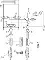
- the system includes at least one actuator 190 to be mechanically connected to a work machine and hydraulically connected to the system 100.
- An inverter 110 is connected to an electrical energy source or energy unit such as an electrical storage (e.g., one or more batteries) or a generator and controls an electric machine 120 (e.g., an electric motor), optionally in bi-directional speed or torque control mode.
- the electric machine 120 may be mechanically coupled to and drive a hydraulic pump 130, which may be any appropriate type, but is generally a fixed displacement, variable speed pump.
- the inverter may also store energy generated by the electrical machine in the storage when the pump is back-driven by hydraulic fluid, for example, during a down motion of the actuator when under an external load.
- the operator of the system may command a desired actuator speed or force through an input device such as a joystick 150 connected to a controller 140.
- a separate command controller may generate the command signal that is passed to the controller 140, for example if the work machine is being remotely or autonomously controlled.
- the controller 140 issues commands to the inverter 110 which in conjunction with the motor 120 and pump 130 allows generation of bi-directional flow and pressure via the hydraulic pump 130.
- the flow is then directed through load holding valves 170, 180 to the actuator 190 yielding the desired actuator motion.
- FIG 1 shows the load holding valves 170, 180 as being ON/OFF type valves, however either or both of these valves could also be flow-control valves, orifice valves or any other proportionally adjustable valve.
- Exemplary valves are poppet valves so as to prevent leakage through the valves when the valves are closed.
- a flow management system 200 for example as presented in U.S. Patent Application Publication No. 2011/0030364 A1 , controlled by a second inverter 210 and second electric machine 220 and second hydraulic pump 230, provides whatever input flow required by the actuator pump 130 via the shuttle valve 160.
- the actuator pump 130 During an actuator extend motion to lift a load, the actuator pump 130 provides flow into the large volume of the actuator 190 (the piston side) and the flow management system 200 is connected to the actuator pump inlet via the shuttle valve 160, ensuring that the flow difference of large volume minus small volume (the rod side) is provided to the actuator pump 130.
- the actuator pump 130 consumes flow from the large volume of the actuator 190 and the flow management system 200 is connected to the actuator pump outlet via the shuttle valve 160, diverting excess flow of large volume minus small volume back to the flow management system 200 and ultimately to the hydraulic reservoir 135.
- actuator depicted is a cylinder, it is contemplated that other actuators are possible. Further, the orientation of the cylinder may be reversed from that which is shown.
- both load holding valves 170, 180 may be closed to remove the hydraulic load from the pump, reduce consumption of electrical energy and prevent the load from dropping in case the pump drive source is turned off. This may cause the pressure between the load holding valves and pump to decay over time, largely due to leakage in the pump. The pressure between the load holding valves and actuator, however, remains at a level to support the external load without actuator motion.
- FIG. 2 an exemplary embodiment of an electro-hydrostatic actuator system 100 is shown.
- the system is the same as that shown in FIG. 1 , except that the flow management system 200 is hidden to focus on operation of the remaining system.
- Hydraulic connection 214 indicates the to/from connection to the flow management system 200 shown in FIG. 1 .
- the hydraulic actuator 190 is mechanically connected to a work machine and the arrow above the actuator is used to indicate the direction of motion: extension of the actuator.
- the remaining arrows indicate hydraulic fluid flow direction in the system.
- load holding valve 170 In order to enable an actuator extension motion, load holding valve 170 needs to be commanded open as indicated to allow fluid flow from the small volume of the actuator back to the electrically driven pump 130.
- Load holding valve 180 does not have to be commanded open in this case, since the type of valve used in this example includes a check valve that will pass flow freely from pump 130 into the large volume of the actuator.
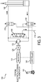
- Fig. 3 an exemplary embodiment of an electro-hydrostatic actuator system is shown.
- the system is the same as that shown in FIG. 1 , except that the flow management system 200 is hidden to focus on operation of the remaining system.
- Hydraulic connection 214 indicates the to/from connection to the flow management system shown as item 200 in Fig. 1 .
- the arrow above the actuator is used to indicate the direction of motion: retraction of the actuator.
- load holding valve 180 In order to enable an actuator retraction motion, load holding valve 180 needs to be commanded open as indicated to allow fluid flow from the large volume of the actuator back to the electrically driven pump 130. Load holding valve 170 does not have to be commanded open in this case, since the type of valve used in this example includes a check valve that will pass flow freely from pump 130 into the large volume of the actuator.
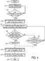
- a signal control flow diagram is shown to support the detailed illustration of process flow of the invention.
- an "operator” or “user” it is contemplated that such method may be employed by an on-site human operator, a remote human operator, or in an autonomous or semi-autonomous mode in which an "operator command” or “user command” is generated by the autonomous or semi-autonomous control program.
- references to the stopping of a "lowering command” or the like encompass any command indicating a stop of the motion of an actuator being acted upon by an external force in an unbalanced manner (i.e., resulting in a net external force on the actuator), and a "lowering command” or the like encompasses any command indicating motion of the actuator in the direction the actuator is acted upon by an external force in an unbalanced manner (i.e., resulting in a net external force on the actuator).
- the logic starts at the initial Start block 415.
- Continuous and/or intermittent monitoring of the operator input device occurs in block 416.
- the decision block 417 defaults the signal flow back to monitoring the operator input device.
- the system in 418 may set the first side of the hydraulic circuit (e.g., pump rod side, although the piston side may alternatively or additionally controlled in a similar manner) pressure limit to a reduced value.
- the first side of the hydraulic circuit e.g., pump rod side, although the piston side may alternatively or additionally controlled in a similar manner
- control valves and pumps may be activated to achieve a desired lowering motion at 419.
- the method may continuously or periodically monitor a condition indicative of the pressure exceeding the limit, such as, for example, the pump speed for a decreasing speed condition and/or the rod side pressure for a saturating condition at block 420.
- a condition indicative of the pressure exceeding the limit such as, for example, the pump speed for a decreasing speed condition and/or the rod side pressure for a saturating condition at block 420.
- block 420 may look to see if the command is being executed as requested. If not, this condition may indicate that the system needs a higher pressure limit to implement the request command.
- a way of monitoring the first-side pressure is to monitor motor torque. If the torque setting is a reduced torque setting and the limit is quickly reached, this may be an indication that the limit needs to be raised. Another alternative is to measure pressure directly via an optional pressure sensor in the hydraulic circuit.
- Another means of limiting the first-side pressure may be to control a pressure relief valve on the first side of the hydraulic circuit and set the pressure limit at which the valve opens at a relatively low pressure. Once the limit is reached, the valve would open and dump pressure to tank in order to control pressure on this side of the system. The limit could then be increased by the controller. However, usage of this means of regulating pressure in the hydraulic circuit would generally be considered less efficient than regulating pump pressure vie a torque/current limitation.
- the system checks for a removal or reversal of the operator command at block 421.
- the first side pressure limit is set to a normal value at 422.
- "normal” means the operating pressure that would be used to control the function given the command absent the desire the mimic a conventional load sense "hesitation" when a function is impeded by a load. This value may simply be set so as to prevent damage to the system, for example.
- setting the value to "normal" at block 422 may include ramping up the pressure limit setting in a gradual manner (either linearly or non-linearly) in order to effectuate the desired delay to mimic a load-sense system.
- Optional block 425 may add a prescribed delay in addition to that inherent in the system in order to achieve the desired hesitation when a function is impeded by a load during movement.
- This delay may be a fixed value, or may depend upon one or more other factors such as, for example, pump type, velocity of actuator, pump wear, commanded speed, personal preference of the operator, etc.
- the pump and/or control valves may then be commanded to implement and achieve the desired motion at block 423 and the process ends at block 424.
- processing blocks denote "processing blocks” that may be implemented with logic.
- the processing blocks may represent a method step or an apparatus element for performing the method step.
- a flow diagram does not depict syntax for any particular programming language, methodology, or style (e.g., procedural, object-oriented). Rather, a flow diagram illustrates functional information one skilled in the art may employ to develop logic to perform the illustrated processing. It will be appreciated that in some examples, program elements like temporary variables, routine loops, and so on, are not shown. It will be further appreciated that electronic and software applications may involve dynamic and flexible processes so that the illustrated blocks can be performed in other sequences that are different from those shown or that blocks may be combined or separated into multiple components. It will be appreciated that the processes may be implemented using various programming approaches like machine language, procedural, object oriented or artificial intelligence techniques.
- methodologies are implemented as processor executable instructions or operations provided on a computer-readable medium.
- a computer-readable medium may store processor executable instructions operable to perform a method.
- FIG. 4 illustrates various actions occurring in serial, it is to be appreciated that various actions illustrated in FIG. 4 could occur substantially in parallel.
- Logic includes but is not limited to hardware, firmware, software or combinations of each to perform a function(s) or an action(s), or to cause a function or action from another logic, method, or system.
- logic may include a software controlled microprocessor, discrete logic like an application specific integrated circuit (ASIC), a programmed logic device, a memory device containing instructions, or the like.
- ASIC application specific integrated circuit
- Logic may include one or more gates, combinations of gates, or other circuit components.
- Logic may also be fully embodied as software. Where multiple logical logics are described, it may be possible to incorporate the multiple logical logics into one physical logic. Similarly, where a single logical logic is described, it may be possible to distribute that single logical logic between multiple physical logics.
- Software includes but is not limited to, one or more computer or processor instructions that can be read, interpreted, compiled, or executed and that cause a computer, processor, or other electronic device to perform functions, actions or behave in a desired manner.
- the instructions may be embodied in various forms like routines, algorithms, modules, methods, threads, or programs including separate applications or code from dynamically or statically linked libraries.
- Software may also be implemented in a variety of executable or loadable forms including, but not limited to, a stand-alone program, a function call (local or remote), a servelet, an applet, instructions stored in a memory, part of an operating system or other types of executable instructions.
- Suitable software for implementing the various components of the example systems and methods described herein may be produced using programming languages and tools like Java, Java Script, Java.NET, ASP.NET, VB.NET, Cocoa, Pascal, C#, C++, C, CGI, Perl, SQL, APIs, SDKs, assembly, firmware, microcode, or other languages and tools.
- Software whether an entire system or a component of a system, may be embodied as an article of manufacture and maintained or provided as part of a computer-readable medium.
- Algorithmic descriptions and representations used herein are the means used by those skilled in the art to convey the substance of their work to others.
- An algorithm or method is here, and generally, conceived to be a sequence of operations that produce a result.
- the operations may include physical manipulations of physical quantities.
- the physical quantities take the form of electrical or magnetic signals capable of being stored, transferred, combined, compared, and otherwise manipulated in a logic and the like.
Landscapes
- Engineering & Computer Science (AREA)
- Physics & Mathematics (AREA)
- Fluid Mechanics (AREA)
- Mechanical Engineering (AREA)
- General Engineering & Computer Science (AREA)
- Chemical & Material Sciences (AREA)
- Analytical Chemistry (AREA)
- Fluid-Pressure Circuits (AREA)
Claims (15)
- Système électro-hydrostatique (100) comprenant :une unité de commande (140) reliée à une interface opérateur,une pompe (130) pouvant fonctionner dans une première direction pour fournir un fluide sous pression,une machine électrique (120) actionnée par l'unité de commande (140) et reliée à une source électrique à travers un onduleur (110) pour entraîner la pompe (130), etun circuit hydraulique ayant un premier côté reliant de manière fluidique un premier côté de la pompe (130) à un premier orifice de liaison à un consommateur (190), et un deuxième côté reliant de manière fluidique le deuxième côté de la pompe (130) à un deuxième orifice de liaison au consommateur (190),où l'unité de commande (140) est configurée pour recevoir une entrée utilisateur pour commander le consommateur (190) et pour fournir un fluide hydraulique conformément à celle-ci,caractérisé en ce que l'unité de commande est en outre configurée :pour régler le premier côté de la limite de pression de circuit hydraulique à une limite de pression de valeur réduite en réponse à l'entrée utilisateur,pour surveiller un paramètre, le paramètre indiquant le fait que la pression dans le premier côté du circuit hydraulique dépasse la limite de pression de valeur réduite,pour limiter la pression dans le premier côté du circuit hydraulique jusqu'à ce que la limite de pression augmente en réponse au paramètre indiquant le fait que la pression dépasse la limite de pression de valeur réduite, retardant ainsi le mouvement du consommateur (190) sauf si une instruction pour arrêter le mouvement du consommateur (190) est donnée et simulant la réactivité dans un système de détection de charge classique, etpour déterminer qu'il faut augmenter la limite de pression sur la base de la réception du paramètre indiquant le fait que la pression dépasse la limite de pression de valeur réduite.
- Système hydraulique (100) de la revendication 1, comprenant en outre un système de soupape relié de manière fluidique entre la pompe (130) et les orifices, le système de soupape étant commandé par l'unité de commande (140) et fonctionnant pour réguler le fluide sous pression entre la pompe (130) et le consommateur (190), et le système de soupape comportant de préférence une soupape de maintien de charge (170) reliée entre la pompe (130) et le premier orifice, la soupape de maintien de charge (170) étant de préférence commandée par l'unité de commande (140) et fonctionnant dans une première position pour permettre un écoulement vers le consommateur afin de faire fonctionner le consommateur (190) contre une charge et fonctionnant dans une deuxième position pour bloquer l'écoulement de retour induit par une charge depuis le consommateur (190) vers la pompe (130).
- Système hydraulique (100) de l'une des revendications précédentes, dans lequel l'instruction d'utilisateur est une instruction pour abaisser un actionneur (190), et dans lequel le consommateur (190) est un vérin hydraulique et le premier côté du circuit hydraulique est relié de manière fluidique à un côté tige du vérin hydraulique (190), et dans lequel l'unité de commande (140) est en outre configurée pour retarder l'augmentation de la limite de pression après avoir déterminé qu'il faut augmenter la limite de pression sur la base de la réception du paramètre indiquant le fait que la pression dépasse la limite de pression de valeur réduite.
- Système hydraulique (100) de l'une des revendications précédentes, dans lequel le paramètre est une vitesse de pompe, un état de mouvement du consommateur (190), un couple de machine électrique, ou une pression dans le premier côté du circuit hydraulique.
- Système hydraulique (100) de l'une des revendications précédentes, dans lequel l'unité de commande (140) est en outre configurée pour limiter la pression par réglage d'une limite de couple de la machine électrique (120).
- Système hydraulique (100) de l'une des revendications précédentes, dans lequel la pompe (130) est une pompe bidirectionnelle pouvant fonctionner dans une première direction pour fournir un fluide sous pression à travers la première soupape (170) au consommateur (190) pour faire fonctionner le consommateur (190) dans une direction, et pouvant fonctionner dans une deuxième direction opposée à la première direction pour fournir un fluide sous pression à travers une deuxième soupape (180) au consommateur (190) pour faire fonctionner le consommateur dans une direction opposée à la première direction, et comprenant en outre :un actionneur hydraulique (190) vers lequel et à partir duquel le fluide hydraulique est fourni et renvoyé dans des directions opposées pour faire fonctionner l'actionneur (190) dans des directions opposées.
- Système hydraulique (100) de l'une des revendications précédentes, comprenant en outre :un système de suralimentation pour accepter un fluide provenant du circuit hydraulique du système hydraulique (100) ou pour fournir un fluide à celui-ci,où le système de suralimentation comporte :une pompe de suralimentation pour fournir un fluide à une conduite d'appoint/de retour de fluide qui est sélectivement en communication fluidique avec le consommateur, et une machine électrique de suralimentation pour entraîner la pompe de suralimentation, la machine électrique (120) étant reliée à une source de puissance électrique de suralimentation à travers un onduleur survolteur.
- Procédé permettant d'empêcher un sur-actionnement dans un système électro-hydrostatique (100), le procédé comprenant les étapes consistant :à recevoir une instruction de consommateur demandée,à régler une limite de pression maximale d'un premier côté d'un circuit hydraulique relié de manière fluidique au consommateur (190) à une première valeur en réponse à l'instruction de consommateur demandée,à commander une pompe (130) et un système de soupape dans le circuit hydraulique pour réaliser l'instruction de consommateur demandée,à entraîner la pompe (130) par l'intermédiaire d'une machine électrique (120) reliée à une source électrique à travers un onduleur (110),à surveiller une première condition de système, la première condition de système indiquant le fait que la pression dans le premier côté du circuit hydraulique dépasse la première valeur,à limiter la pression dans le premier côté du circuit hydraulique jusqu'à ce que la limite de pression augmente,à évaluer la condition de système surveillée avec un critère prescrit en réponse à l'instruction de consommateur demandée, età déterminer s'il faut augmenter ou non la limite de pression maximale sur la base de l'évaluation,retardant ainsi le mouvement du consommateur (190) sauf si une instruction pour arrêter le mouvement du consommateur (190) est donnée et simulant la réactivité dans un système de détection de charge classique.
- Procédé de la revendication 8, dans lequel l'instruction de consommateur est une instruction pour abaisser un actionneur (190), où le consommateur (190) est un vérin hydraulique et le premier côté du circuit hydraulique est relié de manière fluidique à un côté tige du vérin hydraulique (190), où l'unité de commande (140) est en outre configurée pour retarder l'augmentation de la limite de pression maximale après avoir déterminé qu'il faut augmenter la limite de pression maximale sur la base de l'évaluation, et
où la première condition de système est une vitesse de pompe, un état de mouvement du consommateur (190), une pression dans le premier côté du circuit hydraulique, ou
un couple de machine électrique lors de la commande et de l'entraînement de la pompe (130) par l'intermédiaire d'une machine électrique (120). - Procédé de la revendication 8 ou 9, comprenant en outre le fait de commander et d'entraîner la pompe (130) par l'intermédiaire d'une machine électrique (120), où le réglage de la limite de pression maximale comporte le réglage d'une limite de couple de la machine électrique (120).
- Procédé de l'une quelconque des revendications 8 à 10, dans lequel la pompe (130) est une pompe bidirectionnelle pouvant fonctionner dans une première direction pour fournir un fluide sous pression à travers la première soupape (170) à l'actionneur hydraulique (190) pour faire fonctionner l'actionneur (190) dans une direction, et pouvant fonctionner dans une deuxième direction opposée à la première direction pour fournir un fluide sous pression à travers une deuxième soupape (180) à l'actionneur hydraulique (190) pour faire fonctionner l'actionneur (190) dans une direction opposée à la première direction.
- Procédé de l'une quelconque des revendications 8 à 11, dans lequel le consommateur (190) est un actionneur hydraulique vers lequel et à partir duquel le fluide hydraulique est fourni et renvoyé dans des directions opposées pour faire fonctionner l'actionneur (190) dans des directions opposées.
- Procédé de l'une quelconque des revendications 8 à 12, comprenant en outre le fait :d'accepter un fluide provenant d'un circuit hydraulique du système hydraulique (100) ou de fournir un fluide à celui-ci par l'intermédiaire d'un système de suralimentation,où le système de suralimentation comporte :une pompe de suralimentation pour fournir un fluide à une conduite d'appoint/de retour de fluide qui est sélectivement en communication fluidique avec l'actionneur hydraulique (190), et une machine électrique de suralimentation pour entraîner la pompe de suralimentation, la machine électrique (120) étant reliée à une source de puissance électrique de suralimentation à travers un onduleur survolteur.
- Procédé de l'une quelconque des revendications 8 à 13, dans lequel le système de soupape comporte une soupape de maintien de charge (170) reliée entre la pompe (130) et le premier orifice, la soupape de maintien de charge (170) étant commandée par l'unité de commande (140) et fonctionnant dans une première position pour permettre un écoulement vers l'actionneur (190) pour faire fonctionner l'actionneur (190) contre une charge et fonctionnant dans une deuxième position pour bloquer un écoulement de retour induit par la charge depuis l'actionneur (190) vers la pompe (130).
- Procédé de l'une quelconque des revendications 8 à 14, comprenant en outre le fait :de faire fonctionner la pompe (130) dans une direction pour fournir un fluide sous pression à travers la soupape (170) à l'actionneur hydraulique (190) pour faire fonctionner l'actionneur (190) dans une première direction, et de faire fonctionner la pompe (130) dans une deuxième direction opposée à la première direction pour fournir un fluide sous pression à travers une deuxième soupape (180) à l'actionneur hydraulique (190) pour faire fonctionner l'actionneur (190) dans une direction opposée à la première direction.
Applications Claiming Priority (2)
| Application Number | Priority Date | Filing Date | Title |
|---|---|---|---|
| US201361814372P | 2013-04-22 | 2013-04-22 | |
| PCT/US2014/034987 WO2014176256A1 (fr) | 2013-04-22 | 2014-04-22 | Procédé de commande de la pression dans un actionneur hydraulique |
Publications (2)
| Publication Number | Publication Date |
|---|---|
| EP2989334A1 EP2989334A1 (fr) | 2016-03-02 |
| EP2989334B1 true EP2989334B1 (fr) | 2017-06-07 |
Family
ID=50933497
Family Applications (1)
| Application Number | Title | Priority Date | Filing Date |
|---|---|---|---|
| EP14729774.1A Active EP2989334B1 (fr) | 2013-04-22 | 2014-04-22 | Procédé de commande de la pression dans un actionneur hydraulique |
Country Status (5)
| Country | Link |
|---|---|
| US (1) | US9670943B2 (fr) |
| EP (1) | EP2989334B1 (fr) |
| KR (1) | KR102183024B1 (fr) |
| CN (1) | CN105358844B (fr) |
| WO (1) | WO2014176256A1 (fr) |
Families Citing this family (30)
| Publication number | Priority date | Publication date | Assignee | Title |
|---|---|---|---|---|
| WO2015131196A1 (fr) | 2014-02-28 | 2015-09-03 | Project Phoenix, LLC | Pompe intégrée à deux appareils moteurs entraînés indépendamment |
| EP3134648B1 (fr) | 2014-04-22 | 2023-06-14 | Project Phoenix, LLC | Système de distribution de fluide doté d'un arbre ayant un passage traversant |
| EP3149362B1 (fr) | 2014-06-02 | 2019-04-10 | Project Phoenix LLC | Ensemble et système de transmission hydrostatique |
| EP3730793B1 (fr) | 2014-06-02 | 2022-04-27 | Project Phoenix LLC | Ensemble actionneur linéaire et système |
| KR102316426B1 (ko) | 2014-07-22 | 2021-10-21 | 프로젝트 피닉스, 엘엘씨 | 독립적으로 구동되는 2개의 원동기와 통합된 외부 기어 펌프 |
| US10072676B2 (en) | 2014-09-23 | 2018-09-11 | Project Phoenix, LLC | System to pump fluid and control thereof |
| EP3204647B1 (fr) | 2014-10-06 | 2021-05-26 | Project Phoenix LLC | Ensemble actionneur linéaire et système associé |
| WO2016064569A1 (fr) | 2014-10-20 | 2016-04-28 | Afshari Thomas | Ensemble et système de transmission hydrostatique |
| EP3344874B1 (fr) | 2015-09-02 | 2021-01-20 | Project Phoenix LLC | Système de pompage de fluide et commande associée |
| TWI704286B (zh) * | 2015-09-02 | 2020-09-11 | 美商鳳凰計劃股份有限公司 | 泵送流體之系統及其控制 |
| JP6788395B2 (ja) * | 2016-06-30 | 2020-11-25 | Kyb株式会社 | シリンダ駆動装置 |
| US10160279B2 (en) * | 2016-11-23 | 2018-12-25 | GM Global Technology Operations LLC | Hydraulically operated actuator for controlling vehicle ride height |
| CA3037196A1 (fr) | 2016-12-21 | 2018-06-28 | A & A International, Llc | Systeme integre de conversion, de transfert et d'accumulation d'energie |
| EP3558766B1 (fr) * | 2016-12-21 | 2023-11-29 | A&A International, LLC | Système intégré de conversion, de transfert et d'accumulation d'énergie |
| US11072418B2 (en) * | 2018-04-13 | 2021-07-27 | The Boeing Company | Hydraulic system for an aircraft |
| US10711809B2 (en) | 2018-04-13 | 2020-07-14 | The Boeing Company | Aircraft hydraulic system with a dual spool valve and methods of use |
| US10526071B2 (en) | 2018-04-13 | 2020-01-07 | The Boeing Company | Hydraulic systems and methods to control a member |
| US10723441B2 (en) | 2018-04-13 | 2020-07-28 | The Boeing Company | High-speed-deployed, drum-brake, inertia disk for rack and pinion rotational inerter |
| US10737764B2 (en) | 2018-04-13 | 2020-08-11 | The Boeing Company | Base flight control member orientation mechanism and control |
| US10793261B2 (en) | 2018-04-13 | 2020-10-06 | The Boeing Company | Electro-mechanically biased supercritical flight control surface loading to reduce high pressure actuation cycles |
| US10947997B2 (en) | 2018-04-13 | 2021-03-16 | The Boeing Company | Aircraft hydraulic system with a dual spool valve and methods of use |
| NO349291B1 (no) | 2019-06-17 | 2025-11-24 | Conrobotix As | Sylinder, hydraulisk system, anleggsmaskin og fremgangsmåte |
| WO2021112728A1 (fr) * | 2019-12-05 | 2021-06-10 | Saab Ab | Actionneur linéaire électro-hydraulique autonome et procédé de régulation de l'actionneur |
| WO2021173742A1 (fr) * | 2020-02-27 | 2021-09-02 | Cnh Industrial America Llc | Système et procédé de commande de plage de vitesse de fonctionnement de pompe d'un véhicule de travail électrique sur la base d'une pression de fluide hydraulique |
| EP4179211A1 (fr) | 2020-07-08 | 2023-05-17 | Project Phoenix, LLC | Commande dynamique d'engrenages dans une pompe à engrenages ayant une configuration entraînement-entraînement |
| TWI826800B (zh) | 2020-07-08 | 2023-12-21 | 美商鳳凰計劃股份有限公司 | 具有驅動-驅動組態的齒輪泵中之齒輪的動態控制 |
| JP2024035295A (ja) | 2022-09-02 | 2024-03-14 | 川崎重工業株式会社 | 液圧ポンプの性能低下検知システム |
| JP2024035294A (ja) * | 2022-09-02 | 2024-03-14 | 川崎重工業株式会社 | 液圧ポンプの性能低下検知システム |
| CN117948268A (zh) | 2022-10-31 | 2024-04-30 | 川崎重工业株式会社 | 液压泵的性能下降检测系统 |
| KR102890484B1 (ko) * | 2023-03-06 | 2025-11-27 | 주식회사 케이씨 | 자동화 가스 공급 시스템의 작동 방법 |
Family Cites Families (18)
| Publication number | Priority date | Publication date | Assignee | Title |
|---|---|---|---|---|
| JPH01133503U (fr) * | 1988-03-03 | 1989-09-12 | ||
| DE19645699A1 (de) * | 1996-11-06 | 1998-05-07 | Schloemann Siemag Ag | Hydrostatisches Getriebe |
| US5941155A (en) * | 1996-11-20 | 1999-08-24 | Kabushiki Kaisha Kobe Seiko Sho | Hydraulic motor control system |
| US6233511B1 (en) | 1997-11-26 | 2001-05-15 | Case Corporation | Electronic control for a two-axis work implement |
| JP3859982B2 (ja) | 2001-04-27 | 2006-12-20 | 株式会社神戸製鋼所 | ハイブリッド建設機械の電力制御装置 |
| US6912849B2 (en) | 2002-04-09 | 2005-07-05 | Komatsu Ltd. | Cylinder driving system and energy regenerating method thereof |
| WO2006088399A1 (fr) | 2005-02-17 | 2006-08-24 | Volvo Construction Equipment Holding Sweden Ab | Agencement et procede pour le controle d'un vehicule de travail |
| SE531309C2 (sv) | 2006-01-16 | 2009-02-17 | Volvo Constr Equip Ab | Styrsystem för en arbetsmaskin och förfarande för styrning av en hydraulcylinder hos en arbetsmaskin |
| US8037807B2 (en) | 2007-05-18 | 2011-10-18 | Caterpillar Inc. | Controlled motion in a hydraulically actuated system |
| CN100491748C (zh) * | 2007-08-01 | 2009-05-27 | 太原理工大学 | 泵阀复合流量匹配进出油口独立控制电液系统 |
| US7827787B2 (en) * | 2007-12-27 | 2010-11-09 | Deere & Company | Hydraulic system |
| EP2252799B1 (fr) | 2008-02-12 | 2014-06-11 | Parker-Hannifin Corporation | Système de gestion d'écoulement pour machine de travail hydraulique |
| WO2010028100A1 (fr) | 2008-09-03 | 2010-03-11 | Parker Hannifin Corporation | Commande de vitesse d'un actionneur hydraulique dissymétrique soumis à des conditions de charge de basculement |
| WO2010030830A1 (fr) | 2008-09-11 | 2010-03-18 | Parker Hannifin Corporation | Procédé de commande d’un système d’actionneur électro-hydraulique possédant plusieurs fonctions |
| SE534002C2 (sv) | 2009-06-24 | 2011-03-29 | Nordhydraulic Ab | Förfarande och anordning för styrning av ett hydraliskt system |
| US9032724B2 (en) | 2010-06-21 | 2015-05-19 | Husco International Inc. | Command based method for allocating fluid flow from a plurality of pumps to multiple hydraulic functions |
| US8844280B2 (en) | 2011-02-28 | 2014-09-30 | Caterpillar Inc. | Hydraulic control system having cylinder flow correction |
| US8966891B2 (en) * | 2011-09-30 | 2015-03-03 | Caterpillar Inc. | Meterless hydraulic system having pump protection |
-
2014
- 2014-04-22 US US14/786,330 patent/US9670943B2/en active Active
- 2014-04-22 EP EP14729774.1A patent/EP2989334B1/fr active Active
- 2014-04-22 CN CN201480035731.8A patent/CN105358844B/zh active Active
- 2014-04-22 KR KR1020157033341A patent/KR102183024B1/ko active Active
- 2014-04-22 WO PCT/US2014/034987 patent/WO2014176256A1/fr not_active Ceased
Non-Patent Citations (1)
| Title |
|---|
| None * |
Also Published As
| Publication number | Publication date |
|---|---|
| CN105358844A (zh) | 2016-02-24 |
| EP2989334A1 (fr) | 2016-03-02 |
| WO2014176256A1 (fr) | 2014-10-30 |
| KR102183024B1 (ko) | 2020-11-26 |
| US9670943B2 (en) | 2017-06-06 |
| KR20160003753A (ko) | 2016-01-11 |
| US20160091004A1 (en) | 2016-03-31 |
| CN105358844B (zh) | 2017-05-24 |
Similar Documents
| Publication | Publication Date | Title |
|---|---|---|
| US9670943B2 (en) | Method for controlling pressure in a hydraulic actuator | |
| EP2917592B1 (fr) | Système de commande de taux de décélération d'actionneur électro-hydrostatique | |
| EP2989333B1 (fr) | Procédé d'augmentation de la vitesse d'un piston d'actionneur électro-hydrostatique | |
| EP2917591B1 (fr) | Commande régulière d'actionneur hydraulique | |
| US9890799B2 (en) | Method to detect hydraulic valve failure in hydraulic system | |
| US9702118B2 (en) | Hydraulic regenerative and recovery parasitic mitigation system | |
| US9556591B2 (en) | Hydraulic system recovering swing kinetic and boom potential energy | |
| US20170130744A1 (en) | System and method for hydraulic energy recovery | |
| US9809958B2 (en) | Engine assist by recovering swing kinetic energy | |
| US9261118B2 (en) | Boom cylinder dig flow regeneration | |
| EP2341191A1 (fr) | Procédé de contrôle de moteur d'oscillation dans un système hydraulique de type à centre ouvert pour excavateur | |
| US20160152261A1 (en) | Hydraulic system with margin based flow supplementation |
Legal Events
| Date | Code | Title | Description |
|---|---|---|---|
| PUAI | Public reference made under article 153(3) epc to a published international application that has entered the european phase |
Free format text: ORIGINAL CODE: 0009012 |
|
| 17P | Request for examination filed |
Effective date: 20151023 |
|
| AK | Designated contracting states |
Kind code of ref document: A1 Designated state(s): AL AT BE BG CH CY CZ DE DK EE ES FI FR GB GR HR HU IE IS IT LI LT LU LV MC MK MT NL NO PL PT RO RS SE SI SK SM TR |
|
| AX | Request for extension of the european patent |
Extension state: BA ME |
|
| DAX | Request for extension of the european patent (deleted) | ||
| GRAP | Despatch of communication of intention to grant a patent |
Free format text: ORIGINAL CODE: EPIDOSNIGR1 |
|
| INTG | Intention to grant announced |
Effective date: 20161130 |
|
| GRAJ | Information related to disapproval of communication of intention to grant by the applicant or resumption of examination proceedings by the epo deleted |
Free format text: ORIGINAL CODE: EPIDOSDIGR1 |
|
| GRAL | Information related to payment of fee for publishing/printing deleted |
Free format text: ORIGINAL CODE: EPIDOSDIGR3 |
|
| GRAS | Grant fee paid |
Free format text: ORIGINAL CODE: EPIDOSNIGR3 |
|
| GRAP | Despatch of communication of intention to grant a patent |
Free format text: ORIGINAL CODE: EPIDOSNIGR1 |
|
| INTG | Intention to grant announced |
Effective date: 20170331 |
|
| AK | Designated contracting states |
Kind code of ref document: B1 Designated state(s): AL AT BE BG CH CY CZ DE DK EE ES FI FR GB GR HR HU IE IS IT LI LT LU LV MC MK MT NL NO PL PT RO RS SE SI SK SM TR |
|
| REG | Reference to a national code |
Ref country code: GB Ref legal event code: FG4D |
|
| GRAA | (expected) grant |
Free format text: ORIGINAL CODE: 0009210 |
|
| REG | Reference to a national code |
Ref country code: CH Ref legal event code: EP Ref country code: AT Ref legal event code: REF Ref document number: 899459 Country of ref document: AT Kind code of ref document: T Effective date: 20170615 |
|
| REG | Reference to a national code |
Ref country code: IE Ref legal event code: FG4D |
|
| REG | Reference to a national code |
Ref country code: DE Ref legal event code: R096 Ref document number: 602014010558 Country of ref document: DE |
|
| REG | Reference to a national code |
Ref country code: SE Ref legal event code: TRGR |
|
| REG | Reference to a national code |
Ref country code: NL Ref legal event code: MP Effective date: 20170607 |
|
| REG | Reference to a national code |
Ref country code: LT Ref legal event code: MG4D |
|
| PG25 | Lapsed in a contracting state [announced via postgrant information from national office to epo] |
Ref country code: LT Free format text: LAPSE BECAUSE OF FAILURE TO SUBMIT A TRANSLATION OF THE DESCRIPTION OR TO PAY THE FEE WITHIN THE PRESCRIBED TIME-LIMIT Effective date: 20170607 Ref country code: FI Free format text: LAPSE BECAUSE OF FAILURE TO SUBMIT A TRANSLATION OF THE DESCRIPTION OR TO PAY THE FEE WITHIN THE PRESCRIBED TIME-LIMIT Effective date: 20170607 Ref country code: HR Free format text: LAPSE BECAUSE OF FAILURE TO SUBMIT A TRANSLATION OF THE DESCRIPTION OR TO PAY THE FEE WITHIN THE PRESCRIBED TIME-LIMIT Effective date: 20170607 Ref country code: GR Free format text: LAPSE BECAUSE OF FAILURE TO SUBMIT A TRANSLATION OF THE DESCRIPTION OR TO PAY THE FEE WITHIN THE PRESCRIBED TIME-LIMIT Effective date: 20170908 Ref country code: NO Free format text: LAPSE BECAUSE OF FAILURE TO SUBMIT A TRANSLATION OF THE DESCRIPTION OR TO PAY THE FEE WITHIN THE PRESCRIBED TIME-LIMIT Effective date: 20170907 Ref country code: ES Free format text: LAPSE BECAUSE OF FAILURE TO SUBMIT A TRANSLATION OF THE DESCRIPTION OR TO PAY THE FEE WITHIN THE PRESCRIBED TIME-LIMIT Effective date: 20170607 |
|
| REG | Reference to a national code |
Ref country code: AT Ref legal event code: MK05 Ref document number: 899459 Country of ref document: AT Kind code of ref document: T Effective date: 20170607 |
|
| PG25 | Lapsed in a contracting state [announced via postgrant information from national office to epo] |
Ref country code: LV Free format text: LAPSE BECAUSE OF FAILURE TO SUBMIT A TRANSLATION OF THE DESCRIPTION OR TO PAY THE FEE WITHIN THE PRESCRIBED TIME-LIMIT Effective date: 20170607 Ref country code: NL Free format text: LAPSE BECAUSE OF FAILURE TO SUBMIT A TRANSLATION OF THE DESCRIPTION OR TO PAY THE FEE WITHIN THE PRESCRIBED TIME-LIMIT Effective date: 20170607 Ref country code: BG Free format text: LAPSE BECAUSE OF FAILURE TO SUBMIT A TRANSLATION OF THE DESCRIPTION OR TO PAY THE FEE WITHIN THE PRESCRIBED TIME-LIMIT Effective date: 20170907 Ref country code: RS Free format text: LAPSE BECAUSE OF FAILURE TO SUBMIT A TRANSLATION OF THE DESCRIPTION OR TO PAY THE FEE WITHIN THE PRESCRIBED TIME-LIMIT Effective date: 20170607 |
|
| PG25 | Lapsed in a contracting state [announced via postgrant information from national office to epo] |
Ref country code: SK Free format text: LAPSE BECAUSE OF FAILURE TO SUBMIT A TRANSLATION OF THE DESCRIPTION OR TO PAY THE FEE WITHIN THE PRESCRIBED TIME-LIMIT Effective date: 20170607 Ref country code: EE Free format text: LAPSE BECAUSE OF FAILURE TO SUBMIT A TRANSLATION OF THE DESCRIPTION OR TO PAY THE FEE WITHIN THE PRESCRIBED TIME-LIMIT Effective date: 20170607 Ref country code: AT Free format text: LAPSE BECAUSE OF FAILURE TO SUBMIT A TRANSLATION OF THE DESCRIPTION OR TO PAY THE FEE WITHIN THE PRESCRIBED TIME-LIMIT Effective date: 20170607 Ref country code: CZ Free format text: LAPSE BECAUSE OF FAILURE TO SUBMIT A TRANSLATION OF THE DESCRIPTION OR TO PAY THE FEE WITHIN THE PRESCRIBED TIME-LIMIT Effective date: 20170607 Ref country code: RO Free format text: LAPSE BECAUSE OF FAILURE TO SUBMIT A TRANSLATION OF THE DESCRIPTION OR TO PAY THE FEE WITHIN THE PRESCRIBED TIME-LIMIT Effective date: 20170607 |
|
| PG25 | Lapsed in a contracting state [announced via postgrant information from national office to epo] |
Ref country code: IT Free format text: LAPSE BECAUSE OF FAILURE TO SUBMIT A TRANSLATION OF THE DESCRIPTION OR TO PAY THE FEE WITHIN THE PRESCRIBED TIME-LIMIT Effective date: 20170607 Ref country code: SM Free format text: LAPSE BECAUSE OF FAILURE TO SUBMIT A TRANSLATION OF THE DESCRIPTION OR TO PAY THE FEE WITHIN THE PRESCRIBED TIME-LIMIT Effective date: 20170607 Ref country code: IS Free format text: LAPSE BECAUSE OF FAILURE TO SUBMIT A TRANSLATION OF THE DESCRIPTION OR TO PAY THE FEE WITHIN THE PRESCRIBED TIME-LIMIT Effective date: 20171007 Ref country code: PL Free format text: LAPSE BECAUSE OF FAILURE TO SUBMIT A TRANSLATION OF THE DESCRIPTION OR TO PAY THE FEE WITHIN THE PRESCRIBED TIME-LIMIT Effective date: 20170607 |
|
| REG | Reference to a national code |
Ref country code: DE Ref legal event code: R097 Ref document number: 602014010558 Country of ref document: DE |
|
| PLBE | No opposition filed within time limit |
Free format text: ORIGINAL CODE: 0009261 |
|
| STAA | Information on the status of an ep patent application or granted ep patent |
Free format text: STATUS: NO OPPOSITION FILED WITHIN TIME LIMIT |
|
| REG | Reference to a national code |
Ref country code: FR Ref legal event code: PLFP Year of fee payment: 5 |
|
| PG25 | Lapsed in a contracting state [announced via postgrant information from national office to epo] |
Ref country code: DK Free format text: LAPSE BECAUSE OF FAILURE TO SUBMIT A TRANSLATION OF THE DESCRIPTION OR TO PAY THE FEE WITHIN THE PRESCRIBED TIME-LIMIT Effective date: 20170607 |
|
| 26N | No opposition filed |
Effective date: 20180308 |
|
| PG25 | Lapsed in a contracting state [announced via postgrant information from national office to epo] |
Ref country code: SI Free format text: LAPSE BECAUSE OF FAILURE TO SUBMIT A TRANSLATION OF THE DESCRIPTION OR TO PAY THE FEE WITHIN THE PRESCRIBED TIME-LIMIT Effective date: 20170607 |
|
| PG25 | Lapsed in a contracting state [announced via postgrant information from national office to epo] |
Ref country code: MC Free format text: LAPSE BECAUSE OF FAILURE TO SUBMIT A TRANSLATION OF THE DESCRIPTION OR TO PAY THE FEE WITHIN THE PRESCRIBED TIME-LIMIT Effective date: 20170607 |
|
| REG | Reference to a national code |
Ref country code: CH Ref legal event code: PL |
|
| REG | Reference to a national code |
Ref country code: BE Ref legal event code: MM Effective date: 20180430 |
|
| REG | Reference to a national code |
Ref country code: IE Ref legal event code: MM4A |
|
| PG25 | Lapsed in a contracting state [announced via postgrant information from national office to epo] |
Ref country code: LU Free format text: LAPSE BECAUSE OF NON-PAYMENT OF DUE FEES Effective date: 20180422 |
|
| PG25 | Lapsed in a contracting state [announced via postgrant information from national office to epo] |
Ref country code: CH Free format text: LAPSE BECAUSE OF NON-PAYMENT OF DUE FEES Effective date: 20180430 Ref country code: LI Free format text: LAPSE BECAUSE OF NON-PAYMENT OF DUE FEES Effective date: 20180430 Ref country code: BE Free format text: LAPSE BECAUSE OF NON-PAYMENT OF DUE FEES Effective date: 20180430 |
|
| PG25 | Lapsed in a contracting state [announced via postgrant information from national office to epo] |
Ref country code: IE Free format text: LAPSE BECAUSE OF NON-PAYMENT OF DUE FEES Effective date: 20180422 |
|
| PG25 | Lapsed in a contracting state [announced via postgrant information from national office to epo] |
Ref country code: MT Free format text: LAPSE BECAUSE OF NON-PAYMENT OF DUE FEES Effective date: 20180422 |
|
| PG25 | Lapsed in a contracting state [announced via postgrant information from national office to epo] |
Ref country code: TR Free format text: LAPSE BECAUSE OF FAILURE TO SUBMIT A TRANSLATION OF THE DESCRIPTION OR TO PAY THE FEE WITHIN THE PRESCRIBED TIME-LIMIT Effective date: 20170607 |
|
| PG25 | Lapsed in a contracting state [announced via postgrant information from national office to epo] |
Ref country code: PT Free format text: LAPSE BECAUSE OF FAILURE TO SUBMIT A TRANSLATION OF THE DESCRIPTION OR TO PAY THE FEE WITHIN THE PRESCRIBED TIME-LIMIT Effective date: 20170607 |
|
| PG25 | Lapsed in a contracting state [announced via postgrant information from national office to epo] |
Ref country code: MK Free format text: LAPSE BECAUSE OF NON-PAYMENT OF DUE FEES Effective date: 20170607 Ref country code: HU Free format text: LAPSE BECAUSE OF FAILURE TO SUBMIT A TRANSLATION OF THE DESCRIPTION OR TO PAY THE FEE WITHIN THE PRESCRIBED TIME-LIMIT; INVALID AB INITIO Effective date: 20140422 Ref country code: CY Free format text: LAPSE BECAUSE OF FAILURE TO SUBMIT A TRANSLATION OF THE DESCRIPTION OR TO PAY THE FEE WITHIN THE PRESCRIBED TIME-LIMIT Effective date: 20170607 |
|
| PG25 | Lapsed in a contracting state [announced via postgrant information from national office to epo] |
Ref country code: AL Free format text: LAPSE BECAUSE OF FAILURE TO SUBMIT A TRANSLATION OF THE DESCRIPTION OR TO PAY THE FEE WITHIN THE PRESCRIBED TIME-LIMIT Effective date: 20170607 |
|
| P01 | Opt-out of the competence of the unified patent court (upc) registered |
Effective date: 20230524 |
|
| PGFP | Annual fee paid to national office [announced via postgrant information from national office to epo] |
Ref country code: DE Payment date: 20250429 Year of fee payment: 12 |
|
| PGFP | Annual fee paid to national office [announced via postgrant information from national office to epo] |
Ref country code: GB Payment date: 20250428 Year of fee payment: 12 |
|
| PGFP | Annual fee paid to national office [announced via postgrant information from national office to epo] |
Ref country code: FR Payment date: 20250425 Year of fee payment: 12 |
|
| PGFP | Annual fee paid to national office [announced via postgrant information from national office to epo] |
Ref country code: SE Payment date: 20250507 Year of fee payment: 12 |