EP2989785B1 - Procédé d'assemblage d'un appareil supplémentaire avec un module de caméra pour un stylo d'injection, et ledit appareil supplémentaire - Google Patents
Procédé d'assemblage d'un appareil supplémentaire avec un module de caméra pour un stylo d'injection, et ledit appareil supplémentaire Download PDFInfo
- Publication number
- EP2989785B1 EP2989785B1 EP14720532.2A EP14720532A EP2989785B1 EP 2989785 B1 EP2989785 B1 EP 2989785B1 EP 14720532 A EP14720532 A EP 14720532A EP 2989785 B1 EP2989785 B1 EP 2989785B1
- Authority
- EP
- European Patent Office
- Prior art keywords
- module
- housing
- camera
- relative
- marker
- Prior art date
- Legal status (The legal status is an assumption and is not a legal conclusion. Google has not performed a legal analysis and makes no representation as to the accuracy of the status listed.)
- Active
Links
Images


Classifications
-
- A—HUMAN NECESSITIES
- A61—MEDICAL OR VETERINARY SCIENCE; HYGIENE
- A61M—DEVICES FOR INTRODUCING MEDIA INTO, OR ONTO, THE BODY; DEVICES FOR TRANSDUCING BODY MEDIA OR FOR TAKING MEDIA FROM THE BODY; DEVICES FOR PRODUCING OR ENDING SLEEP OR STUPOR
- A61M5/00—Devices for bringing media into the body in a subcutaneous, intra-vascular or intramuscular way; Accessories therefor, e.g. filling or cleaning devices, arm rests
- A61M5/178—Syringes
- A61M5/24—Ampoule syringes, i.e. syringes with needle for use in combination with replaceable ampoules or cartridges, e.g. automatic
-
- A—HUMAN NECESSITIES
- A61—MEDICAL OR VETERINARY SCIENCE; HYGIENE
- A61M—DEVICES FOR INTRODUCING MEDIA INTO, OR ONTO, THE BODY; DEVICES FOR TRANSDUCING BODY MEDIA OR FOR TAKING MEDIA FROM THE BODY; DEVICES FOR PRODUCING OR ENDING SLEEP OR STUPOR
- A61M5/00—Devices for bringing media into the body in a subcutaneous, intra-vascular or intramuscular way; Accessories therefor, e.g. filling or cleaning devices, arm rests
- A61M5/009—Electronic or electro-mechanical add-on modules
-
- G—PHYSICS
- G06—COMPUTING OR CALCULATING; COUNTING
- G06F—ELECTRIC DIGITAL DATA PROCESSING
- G06F18/00—Pattern recognition
- G06F18/20—Analysing
- G06F18/22—Matching criteria, e.g. proximity measures
-
- G—PHYSICS
- G06—COMPUTING OR CALCULATING; COUNTING
- G06T—IMAGE DATA PROCESSING OR GENERATION, IN GENERAL
- G06T7/00—Image analysis
- G06T7/0002—Inspection of images, e.g. flaw detection
- G06T7/0012—Biomedical image inspection
- G06T7/0014—Biomedical image inspection using an image reference approach
-
- G—PHYSICS
- G06—COMPUTING OR CALCULATING; COUNTING
- G06T—IMAGE DATA PROCESSING OR GENERATION, IN GENERAL
- G06T7/00—Image analysis
- G06T7/70—Determining position or orientation of objects or cameras
-
- H—ELECTRICITY
- H04—ELECTRIC COMMUNICATION TECHNIQUE
- H04N—PICTORIAL COMMUNICATION, e.g. TELEVISION
- H04N23/00—Cameras or camera modules comprising electronic image sensors; Control thereof
- H04N23/50—Constructional details
- H04N23/51—Housings
-
- H—ELECTRICITY
- H04—ELECTRIC COMMUNICATION TECHNIQUE
- H04N—PICTORIAL COMMUNICATION, e.g. TELEVISION
- H04N23/00—Cameras or camera modules comprising electronic image sensors; Control thereof
- H04N23/56—Cameras or camera modules comprising electronic image sensors; Control thereof provided with illuminating means
-
- H—ELECTRICITY
- H04—ELECTRIC COMMUNICATION TECHNIQUE
- H04N—PICTORIAL COMMUNICATION, e.g. TELEVISION
- H04N23/00—Cameras or camera modules comprising electronic image sensors; Control thereof
- H04N23/57—Mechanical or electrical details of cameras or camera modules specially adapted for being embedded in other devices
-
- A—HUMAN NECESSITIES
- A61—MEDICAL OR VETERINARY SCIENCE; HYGIENE
- A61M—DEVICES FOR INTRODUCING MEDIA INTO, OR ONTO, THE BODY; DEVICES FOR TRANSDUCING BODY MEDIA OR FOR TAKING MEDIA FROM THE BODY; DEVICES FOR PRODUCING OR ENDING SLEEP OR STUPOR
- A61M5/00—Devices for bringing media into the body in a subcutaneous, intra-vascular or intramuscular way; Accessories therefor, e.g. filling or cleaning devices, arm rests
- A61M5/178—Syringes
- A61M5/31—Details
- A61M2005/3125—Display means, e.g. to indicate dose setting
-
- A—HUMAN NECESSITIES
- A61—MEDICAL OR VETERINARY SCIENCE; HYGIENE
- A61M—DEVICES FOR INTRODUCING MEDIA INTO, OR ONTO, THE BODY; DEVICES FOR TRANSDUCING BODY MEDIA OR FOR TAKING MEDIA FROM THE BODY; DEVICES FOR PRODUCING OR ENDING SLEEP OR STUPOR
- A61M5/00—Devices for bringing media into the body in a subcutaneous, intra-vascular or intramuscular way; Accessories therefor, e.g. filling or cleaning devices, arm rests
- A61M5/178—Syringes
- A61M5/31—Details
- A61M2005/3125—Display means, e.g. to indicate dose setting
- A61M2005/3126—Display means, e.g. to indicate dose setting related to dosing
-
- A—HUMAN NECESSITIES
- A61—MEDICAL OR VETERINARY SCIENCE; HYGIENE
- A61M—DEVICES FOR INTRODUCING MEDIA INTO, OR ONTO, THE BODY; DEVICES FOR TRANSDUCING BODY MEDIA OR FOR TAKING MEDIA FROM THE BODY; DEVICES FOR PRODUCING OR ENDING SLEEP OR STUPOR
- A61M2205/00—General characteristics of the apparatus
- A61M2205/35—Communication
- A61M2205/3576—Communication with non implanted data transmission devices, e.g. using external transmitter or receiver
- A61M2205/3592—Communication with non implanted data transmission devices, e.g. using external transmitter or receiver using telemetric means, e.g. radio or optical transmission
-
- A—HUMAN NECESSITIES
- A61—MEDICAL OR VETERINARY SCIENCE; HYGIENE
- A61M—DEVICES FOR INTRODUCING MEDIA INTO, OR ONTO, THE BODY; DEVICES FOR TRANSDUCING BODY MEDIA OR FOR TAKING MEDIA FROM THE BODY; DEVICES FOR PRODUCING OR ENDING SLEEP OR STUPOR
- A61M2205/00—General characteristics of the apparatus
- A61M2205/50—General characteristics of the apparatus with microprocessors or computers
- A61M2205/502—User interfaces, e.g. screens or keyboards
Definitions
- An aspect of the present invention relates to a method of assembling an apparatus for use in performing pattern recognition (such as optical character recognition). Another aspect of the present invention relates to a system for assembling said apparatus.
- One previously proposed insulin injection device specifically the SolostarTM injection pen sold by Sanofi, is provided with a window in its outer surface (hereafter referred to as a dosage window).
- a sleeve inside the SolostarTM injection pen (known as the number sleeve) is caused to rotate when an amount of insulin is dialled or dispensed. Numbers on the number sleeve successively align with the dosage window as the sleeve rotates. When an amount of insulin has been dialled, the number corresponding to the dialled amount of insulin (in International Units) is displayed in the dosage window. When insulin is dispensed, rotation of the number sleeve causes the number displayed in the dosage window to be that associated with the dialled amount of insulin remaining in the pen yet to be dispensed.
- WO2011/117212 describes a supplemental device, provided with optical character recognition (OCR) functionality, for reading numbers aligned with the dosage window of an injection device to determine quantities of insulin dialled or delivered. Supplemental devices which use OCR for this purpose obstruct the view of numbers aligned with the dosage window in use.
- a display unit may therefore be provided for displaying an indication to a user of the determined amount of insulin dialled or, in the case of an injection, for displaying an indication of the progress of the injection.
- US2012/0053527 A1 discloses medication injection supervisor devices for use with prefabricated injection pens.
- the medication supervisor device may include a universal header having one or more attachment features for attaching the header to a prefabricated injection pen.
- a sleeve can be mounted on the injection pen, and the universal header installed on the sleeve.
- the universal header may include a micro optics and imaging system for performing image recognition by reading a maximum dial value.
- EP1475960 A2 describes a camera-module manufacturing method wherein a solid-state imaging device with an electronic camera is positioned with respect to an optical lens unit before fixing the solid-state imaging device to the optical lens unit.
- indications on the display unit of the supplemental device described in WO2011/117212 are required to correspond with the actual quantity of insulin dialled or dispensed.
- the indications shown by the display unit should be updated as quickly as possible after a quantity of insulin has been dialled or dispensed.
- an amount of insulin is selected by a user turning a dose dialling knob in a series of twists. After each such twist, the indication shown by the display unit of the currently selected insulin amount should be updated as quickly as possible to reduce the likelihood of a user unnecessarily dialling additional dose.
- the optical character recognition algorithm used to determine the particular numbers aligned with the dosage window should be as efficient as possible.
- a supplemental device for determining an amount of dose delivered by an injection device, the supplemental device comprising a module and a housing, the method comprising:
- this reduces adverse effects caused by camera misalignment when using an apparatus to perform pattern recognition.
- Moving the module and the housing relative to one another may comprise translating the module and the housing relative to one another.
- Moving the module and the housing relative to one another may comprise translating the module and the housing relative to one another without rotation of the module and the housing relative to one another.
- Placing the module and the housing relative to one another may comprise placing the module and the housing against one another.
- Fixing the position of the module relative to the housing may comprise fixing the module to the housing.
- the method may further comprise the step of illuminating the optical marker.
- An illumination device provided on the module may be used to illuminate the optical marker.
- the module and the housing may comprise first and second support portions respectively that are configured to support the module and the housing relative to one another when brought into engagement; and the step of placing the module and the housing relative to one another may comprise engaging the first and second support portions.
- Moving the module and the housing relative to one another may comprise moving one of the support portions within a channel defined by the other support portion.
- this guides the movement of the module and the housing relative to one another.
- the step of determining the position of the marker in the field-of-view of the camera may comprise: determining the difference between the position of the marker in the field-of-view of the camera and the intended position of the marker in the field-of-view of the camera; and determining the extent to which the camera and the marker should be moved relative to one another to offset the difference in positions.
- the method may further comprise continually monitoring the difference in positions until such difference has been offset.
- assembling a supplemental device reduces adverse effects caused by camera misalignment when determining an amount of dose delivered by an injection device.
- a system for assembling a supplemental device for determining an amount of dose delivered by an injection device comprising:
- a supplemental device for determining an amount of dose dialled, or an amount of dose dispensed, by an injection device.
- a supplemental device may be provided with optical character recognition (OCR) functionality for making such a determination.
- OCR optical character recognition
- the present invention is however not limited to such application and may equally well be deployed with other devices that are capable of implementing OCR functionality.
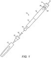
- Figure 1 is an exploded view of an injection device 10, which may for instance represent the SolostarTM injection pen sold by Sanofi.
- the injection device 10 of Figure 1 is a pre-filled, disposable injection pen that comprises a housing 12 and contains an insulin container 14, to which a needle 16 can be affixed.
- the needle 16 is protected by an inner needle cap 18 and an outer needle cap 20, which in turn can be covered by a cap 22.
- An insulin dose to be ejected from injection device 10 can be selected by turning the dosage knob 24 (this act may be referred to as dialling an insulin dose).
- Markers representing numbers 26 indicative of the selected dose are displayed via dosage window 28 in multiples of International Units (IU) for instance.
- An example of a dialled dose displayed in the dosage window 28 may be 30 IUs, as shown in Figure 1 .
- the numbers 26 displayed in the dosage window 28 are printed on a sleeve (known as the number sleeve 17) contained in the housing 12 and which mechanically interacts with a piston inside the insulin container 14.
- a sleeve (known as the number sleeve 17) contained in the housing 12 and which mechanically interacts with a piston inside the insulin container 14.
- the injection button 30 When needle 16 is stuck into the skin of a patient and the injection button 30 is pushed, an amount of insulin corresponding to the dialled quantity displayed in the display window 28 is ejected from the injection device 10.
- the number sleeve 17 rotates. This causes the number 26 displayed in the dosage window 28 to change in accordance with the dialled amount of insulin yet to be dispensed. In other words, during the course of an injection the numbers 26 that successively align with the dosage window 28 are caused to count down.
- Figure 2 shows the dosage window 28 after some of the 30 IUs of insulin previously dialled have been delivered from the injection device 10 during the course of the injection in the preceding paragraph.
- FIG 3 is a schematic illustration of a supplemental device 34 which may be releasably attached to an injection device such as the one depicted in Figure 1 .
- the supplemental device 34 comprises a housing 36 that may comprise multiple parts.
- the housing 36 is provided with a mating unit 37 for embracing the housing 12 of an injection device 10.
- the mating unit 37 may be configured to snap-fit onto the housing 12 of an injection device 10 in such a way that the device 34 can be subsequently removed therefrom.
- the mating unit 37 need not however be of the snap-fit variety and other arrangements may alternatively be suitable for coupling the supplemental device 34 to an injection device 10.
- the supplemental device 34 When coupled to an injection device 10, the supplemental device 34 obstructs the dosage window 28 (as in Figure 4 ).
- the supplemental device 34 comprises a camera for gathering information from the injection device 10.
- the camera (described in more detail later on) is used to gather information indicative of what is displayed in the dosage window 28.
- This gathered information is capable of being processed for generating a dose history database.
- a dose history database may include records containing information about the various times at which insulin doses are administered and the quantity of insulin administered during each dose.
- the gathered information may also be processed for the purpose of displaying the particular number 26 currently aligned with the dosage window 28 in larger format.
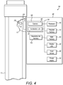
- Figure 4 illustrates an internal schematic view of the supplemental device 34 in a state where it is coupled to an injection device 10.
- a variety of components are located and coupled together by a system bus 35.
- One such component includes a processor 40.
- Program memory 42 and main memory 44 are also coupled to the system bus 35.
- the processor 40 executes program code (e.g. software or firmware) stored in the program memory 42 and uses the main memory 44 to store intermediate results.
- the supplemental device 34 also comprises a supplemental memory 43 for storing the aforementioned dose history database.
- Program memory 42 may for instance be non-volatile memory such as Read-Only Memory.
- Main memory 44 may for instance be a volatile memory such as Random Access Memory, DRAM or SDRAM.
- Supplemental memory 43 may for instance be Flash memory or an EEPROM or may comprise a memory card coupled to the system bus 35 via an interface such as a USB-type connection.
- a camera 46 also coupled to the system bus 35, is used to generate signals containing information indicative of what is displayed in the dosage window 28.
- the processor 40 may use these signals to generate the dose history database.
- the processor 40 could do this by executing an OCR application to determine, from signals sent by the camera 46, which number is aligned with the dosage window 28. On the basis of such information the processor 40 then determines how much insulin has been dialled or, in the case of an injection, the dialled amount of insulin that remains to be delivered (or has already been delivered during the course of the injection).
- the camera 46 may itself be capable of implementing the OCR functionality such that the signals it outputs to the processor 40 are indicative of the number aligned with the dosage window 28.
- the processor 40 may then on the basis of this information determine as above how much insulin has been dialled or, in the case of an injection, the dialled amount of insulin that remains to be delivered (or has already been delivered during the course of the injection).
- an illumination unit 47 may include one or more LEDs and may be controlled by the processor 40 to illuminate information displayed in the dosage window 28.
- An input device 48 (for example, a keypad) may be utilised by a user to interact with the supplemental device 34.
- Such an input device 48 may for instance be used to select one or more options shown on a display unit 38.
- a display unit 38 may be provided with touch-screen functionality thus enabling it to function as both an output device and the input device 48.
- a power supply source 50 (for example a battery) is for powering the various components of the supplemental device 34.
- the housing 36 (or a part thereof in the instance that the housing 36 comprises multiple parts) is supported relative to a reference object 52.
- the reference object 52 corresponds in shape to the part of an injection device 10 to which the supplemental device 34 (once assembled) is configured to be coupled in use and may for instance comprise a reference pin.
- the reference object 52 may comprise a single-piece object produced using a single-stage injection moulding process for example.
- a marker 54 (such as a cross, dot or other indicator) is located on the reference object 52 in a corresponding location that a number 26 would otherwise be viewable when aligned with the dosage window 28 were the reference object 52 in fact an injection device 10.
- a marker 54 may be located on the reference object 52 in a corresponding location to the number "12" shown in Figure 2 .
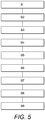
- step S1 could involve coupling the housing 36 to the reference object 52 using mating unit 37 (see Figure 3 ) already coupled to the housing 36 or comprising an integral part thereof.
- step S1 could involve a device, such as a robotic arm, holding the housing 36 relative to the reference object 52 in the position that the housing 36 would otherwise be located relative to the reference object 52 if they were coupled to one another in the manner described in the foregoing sentence.
- a module 56 comprising the camera 46 is placed relative to the housing 36.
- This may involve a device, such as a robotic arm, placing the module 56 relative to the housing 36.
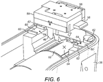
- placing the module 56 relative to the housing 36 could involve placing the module 56 and the housing 36 against one another as in Figure 7 .
- the module 56 and the housing 36 may for instance comprise first and second support portions respectively. These support portions define separate parts of a two-part engagement mechanism which, when engaged, support the module 56 and housing 36 relative to one another.
- the module 56 and the housing 36 together comprise a pair of two-part engagement mechanisms.
- the first part of each such engagement mechanism comprises a protrusion 58 defining a planar surface, one of which extends from either side of the module 56.
- the second part of each such engagement mechanism comprises a guide 60 defining a planar surface, one of which extends internally from either side of the housing 36.
- placing the module 56 relative to the housing 36 involves engaging the planar surfaces defined by the respective protrusions 58 and guides 60.
- the protrusions 58 may instead extend internally from either side of the housing 36 and the module may define guides 60.
- step S3 the camera 46 is used to generate camera output indicative of a scene in the field-of-view of the camera 46.
- a peripheral processing device such as an external computer to the camera 46 for controlling the camera 46 to generate camera output.
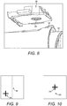
- the camera 46 of the module 56 is directed towards the reference object 52 as shown in Figure 8 .
- the camera 46 is aligned with an aperture 49 through which it is able to view the marker 54.
- the peripheral processing device is able to determine the location of the marker 54 within the field-of-view of the camera 46 in step S4.
- step S5 compares the determined location of the marker 54 in the filed-of-view of the camera 46 with a template stored in a memory for example.
- This template is indicative of the intended location of the marker 54 in the field-of-view of the camera 46.
- Step S5 is represented diagrammatically in Figure 9 , wherein the intended location of the marker 54 in the field-of-view of the camera 46 is represented by the location at which the cross-hairs 65 intersect.
- step S6 the peripheral processing device determines the difference between the actual position of the marker 54 in the field-of-view of the camera 46 and the intended position of the marker 54 in the field-of-view of the camera 46.
- This information is used in step S7 to determine the extent to which the camera 46 and the marker 54 should be moved relative to one another to offset the difference between the actual and intended positions mentioned in the previous sentence. This is equivalent to the extent to which the module 56 and the housing 36 should be moved relative to one another since the relative position of the housing 36 and the reference object 52 is fixed.
- step S8 the module 56 and the housing 36 are moved relative to one another until the marker 54 is located at the intended position in the field-of-view of the camera 46 as shown diagrammatically in Figure 10 .
- This may involve causing either of the aforementioned robotic arms to move the module 56 and housing 36 relative to one another the extent determined in step S7.
- step S8 may further involve the peripheral processing device continually monitoring the position of the marker 54 in the field-of-view of the camera 46 while the module 56 and housing 36 are moved relative to one another. This may be carried out to monitor the difference between the actual and the intended position of the marker 54 in the field-of-view of the camera 46 on-the-fly for the purpose of controlling the relative movement of the module 56 and housing 36 in real-time.
- the peripheral processing device may check whether the marker 54 is in the intended position in the field-of-view of the camera 46 after the module 56 and housing 36 have been moved relative to one another. If a negative determination is made then steps S3 to S8 are repeated until the marker 54 is located in the intended position in the field-of-view of the camera 46.
- step S8 in the example shown in Figures 6 and 7 involves sliding the protrusions 58 across the guides 60.
- the range of movement of the protrusions 58 is restricted in this particular example by walls 62 which thereby define channels 64.
- the channels 64 provide that, in the present example, the module 56 may only slide along the axis A-A relative to the marker 54.
- the space between walls 62 may be such that the channels 64 are wider than the protrusions 58. This will allow the module 56 to be additionally slid relative to the marker 54 along an axis perpendicular to the one denoted A-A.
- such walls 62 may alternatively not be provided.
- step S9 the position of the module 56 relative to the housing 36 is fixed.
- this may involve one or more of clamping, adhering or welding the module 56 to the housing 36.
- This provides that the module 56 and housing 36 are fixed relative to one another in a position where the marker 54 is located in the intended position in the field-of-view of the camera 46. Therefore, in use, numbers 26 on the number sleeve 17 of an injection device 10 will move through this position in the field-of-view of the camera 46.
- supplemental device 34 may subsequently be coupled to the housing 36 in ways familiar to persons skilled in the art (unless they were coupled to the housing 36 before the module 56). Also the housing 36, if it comprises multiple parts, may be sealed shut by coupling the various parts of the housing 36 together.
- assembling a supplemental device 34 reduces adverse effects caused by camera misalignment with numbers 26 in the dosage window 28 of an injection device 10.
- the effects of such misalignment are reduced without enhancing the algorithm used to perform OCR.
- the module 56 may not be coupled directly to the housing.
- a component such as a battery module (not shown) may be fixed to the housing 36, and the module 56 may be fixed to the battery module in a similar manner to that heretofore described.
- the module 56 and the battery module may comprise first and second parts of a two-part engagement mechanism respectively.
- the module may comprise a protrusion 58 and the battery module may define a guide 60 to which the protrusion may be coupled.
- step S3 may further involve the peripheral processing device (not shown) controlling the illumination unit 47 to illuminate the marker 54 provided on the reference object 52.
- the marker 54 may be provided on a transparent area of the reference object 52 which is capable of being backlit.
- An illumination unit may be located behind the marker 54.
- Step S3 may thus further involve activating such an illumination unit for the purpose of directing light towards the camera 46 via the transparent area of the reference object 52 on which the marker 54 is provided. This improves the visibility of the marker 54.
- step S8 could involve rotating the module 56 relative to the housing 36. To enable this, the module 56 may be able to pivot about the respective protrusions 58 for instance. In such an embodiment, step S9 will therefore involve fixing the rotational position of the module 56.
- an injection device 10 may instead be used for the same purpose.
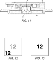
- a number for instance "0" or "12" on the number sleeve 17, may be used for the same purpose as shown diagrammatically in Figures 12 and 13 .
- a supplemental device 34 for implementing OCR functionality
- OCR is only one type of pattern recognition functionality.
- the teachings of the present invention may be applied in the context of a device, for instance a supplemental device 34, for implementing any type of pattern recognition functionality.
- the supplemental device 34 instead of numbers 26 the supplemental device 34 for instance could be used to recognise letters, symbols or respective sections of a code provided on the number sleeve 17 of an injection device 10.
- the processor 40 may determine an amount of dose dialled or, during the course of an injection, the dialled amount of dose yet to be delivered (or has already been delivered during the course of the injection).
- an operator may implement one or more of the steps in Figure 5 .
- the camera output generated in step S3 may be shown on an operator's monitor.
- the operator may thus view what is shown in Figure 9 for example.
- the operator then moves the module 56 and housing 36 relative to one another until the marker 54 displayed on their monitor is located at the intersection of the crosshairs 65.
- the operator's monitor will display what is shown in Figure 10 .
- the operator may physically manipulate the module 56 in order to move it relative to the housing 36 or alternatively they may use a manually operated device for this purpose such as a clamping tool comprising a micrometer screw.
Landscapes
- Engineering & Computer Science (AREA)
- Health & Medical Sciences (AREA)
- Theoretical Computer Science (AREA)
- Signal Processing (AREA)
- Multimedia (AREA)
- General Physics & Mathematics (AREA)
- General Health & Medical Sciences (AREA)
- Computer Vision & Pattern Recognition (AREA)
- Physics & Mathematics (AREA)
- Life Sciences & Earth Sciences (AREA)
- Veterinary Medicine (AREA)
- Vascular Medicine (AREA)
- Anesthesiology (AREA)
- Biomedical Technology (AREA)
- Heart & Thoracic Surgery (AREA)
- Hematology (AREA)
- Animal Behavior & Ethology (AREA)
- Public Health (AREA)
- Data Mining & Analysis (AREA)
- Nuclear Medicine, Radiotherapy & Molecular Imaging (AREA)
- Quality & Reliability (AREA)
- Medical Informatics (AREA)
- Radiology & Medical Imaging (AREA)
- Artificial Intelligence (AREA)
- Bioinformatics & Cheminformatics (AREA)
- Bioinformatics & Computational Biology (AREA)
- Evolutionary Biology (AREA)
- Evolutionary Computation (AREA)
- General Engineering & Computer Science (AREA)
- Infusion, Injection, And Reservoir Apparatuses (AREA)
- Image Input (AREA)
- Studio Devices (AREA)
Claims (14)
- Procédé d'assemblage d'un dispositif complémentaire destiné à être utilisé dans la réalisation d'une reconnaissance de motif en vue de déterminer une quantité de dose délivrée par un dispositif d'injection, le dispositif complémentaire comprenant un module (56) et un boîtier (36), le procédé comprenant :le positionnement du module (56) et du boîtier (36) l'un par rapport à l'autre, le boîtier étant supporté par rapport à un objet de référence (52) sur lequel est disposé un repère optique (54), l'objet correspondant en forme à une partie d'un dispositif d'injection auquel le dispositif complémentaire est configuré pour être couplé à l'usage, et le module comprenant une caméra (46) pour générer une sortie de caméra indicative d'une scène dans le champ de vision de la caméra ;l'utilisation de la sortie de caméra pour déterminer la position du repère dans le champ de vision de la caméra ;la comparaison de la position déterminée du repère avec un modèle indicatif d'une position prévue du repère dans le champ de vision de la caméra ; etle déplacement, sur la base de la comparaison, du module et du boîtier l'un par rapport à l'autre jusqu'à ce que le repère soit à l'emplacement prédéterminé dans le champ de vision de la caméra puis la fixation de la position du module par rapport au boîtier.
- Procédé de la revendication 1, dans lequel le déplacement du module (56) et du boîtier (36) l'un par rapport à l'autre comprend la translation du module et du boîtier l'un par rapport à l'autre.
- Procédé de la revendication 1, dans lequel le déplacement du module (56) et du boîtier (36) l'un par rapport à l'autre comprend la translation du module et du boîtier l'un par rapport à l'autre sans rotation du module et du boîtier l'un par rapport à l'autre.
- Procédé d'une quelconque revendication précédente, dans lequel le positionnement du module (56) et du boîtier (36) l'un par rapport à l'autre comprend le positionnement du module et du boîtier l'un contre l'autre.
- Procédé d'une quelconque revendication précédente, dans lequel la fixation de la position du module (56) par rapport au boîtier (36) comprend la fixation du module au boîtier.
- Procédé d'une quelconque revendication précédente, comprenant en outre l'étape d'éclairage du repère optique (54).
- Procédé de la revendication 6, dans lequel un dispositif d'éclairage (47) disposé sur le module est utilisé pour éclairer le repère optique (54).
- Procédé d'une quelconque revendication précédente, dans lequel :le module (56) et le boîtier (36) comprennent des première et deuxième portions de support, respectivement, qui sont configurées pour supporter le module et le boîtier l'un par rapport à l'autre lorsqu'elles sont mises en prise ; etl'étape de positionnement du module et du boîtier l'un par rapport à l'autre comprend la mise en prise des première et deuxième portions de support.
- Procédé de la revendication 8, dans lequel le déplacement du module (56) et du boîtier (36) l'un par rapport à l'autre comprend le déplacement d'une des portions de support à l'intérieur d'un canal (64) défini par l'autre portion de support.
- Procédé d'une quelconque revendication précédente, dans lequel l'étape de détermination de la position du repère (54) dans le champ de vision de la caméra (46) comprend :la détermination de la différence entre la position du repère dans le champ de vision de la caméra et la position prévue du repère dans le champ de vision de la caméra ; etla détermination de l'étendue sur laquelle la caméra et le repère devraient être déplacés l'un par rapport à l'autre pour compenser la différence de positions.
- Procédé de la revendication 10, comprenant en outre la surveillance continue de la différence de positions jusqu'à ce que cette différence ait été compensée.
- Procédé d'une quelconque revendication précédente, dans lequel le déplacement, sur la base de la comparaison, du module (56) et du boîtier (36) l'un par rapport à l'autre comprend l'utilisation d'un ou de plusieurs bras robotiques.
- Système destiné à assembler un dispositif complémentaire (34) destiné à être utilisé dans la réalisation d'une reconnaissance de motif en vue de déterminer une quantité de dose délivrée par un dispositif d'injection, le dispositif complémentaire comprenant un module (56) et un boîtier (36), le système comprenant :un dispositif de positionnement pour positionner le module et le boîtier l'un par rapport à l'autre, le boîtier étant supporté par rapport à un objet de référence (52) sur lequel est disposé un repère optique (54), l'objet correspondant en forme à une partie d'un dispositif d'injection auquel le dispositif complémentaire est configuré pour être couplé à l'usage, et le module comprenant une caméra (46) pour générer une sortie de caméra indicative d'une scène dans le champ de vision de la caméra ;un dispositif de détermination pour utiliser la sortie de caméra pour déterminer la position du repère dans le champ de vision de la caméra et comparer la position déterminée du repère avec un modèle indicatif d'une position prévue du repère dans le champ de vision de la caméra ;un dispositif de déplacement pour déplacer le module et le boîtier l'un par rapport à l'autre jusqu'à ce que le repère soit à un emplacement prédéterminé dans le champ de vision de la caméra ; etun dispositif de fixation pour fixer la position du module par rapport au boîtier quand le repère est à l'emplacement prédéterminé dans le champ de vision de la caméra.
- Système de la revendication 13, dans lequel le dispositif de déplacement comprend un ou plusieurs bras robotiques.
Priority Applications (1)
| Application Number | Priority Date | Filing Date | Title |
|---|---|---|---|
| EP14720532.2A EP2989785B1 (fr) | 2013-04-22 | 2014-04-16 | Procédé d'assemblage d'un appareil supplémentaire avec un module de caméra pour un stylo d'injection, et ledit appareil supplémentaire |
Applications Claiming Priority (3)
| Application Number | Priority Date | Filing Date | Title |
|---|---|---|---|
| EP13164757 | 2013-04-22 | ||
| EP14720532.2A EP2989785B1 (fr) | 2013-04-22 | 2014-04-16 | Procédé d'assemblage d'un appareil supplémentaire avec un module de caméra pour un stylo d'injection, et ledit appareil supplémentaire |
| PCT/EP2014/057787 WO2014173774A1 (fr) | 2013-04-22 | 2014-04-16 | Procédé d'assemblage d'un dispositif supplémentaire comprenant un module de caméra pour un stylo injecteur et ledit dispositif supplémentaire |
Publications (2)
| Publication Number | Publication Date |
|---|---|
| EP2989785A1 EP2989785A1 (fr) | 2016-03-02 |
| EP2989785B1 true EP2989785B1 (fr) | 2020-04-15 |
Family
ID=48143519
Family Applications (1)
| Application Number | Title | Priority Date | Filing Date |
|---|---|---|---|
| EP14720532.2A Active EP2989785B1 (fr) | 2013-04-22 | 2014-04-16 | Procédé d'assemblage d'un appareil supplémentaire avec un module de caméra pour un stylo d'injection, et ledit appareil supplémentaire |
Country Status (6)
| Country | Link |
|---|---|
| US (1) | US10298816B2 (fr) |
| EP (1) | EP2989785B1 (fr) |
| JP (1) | JP6417396B2 (fr) |
| CN (1) | CN105122786B (fr) |
| DK (1) | DK2989785T3 (fr) |
| WO (1) | WO2014173774A1 (fr) |
Families Citing this family (18)
| Publication number | Priority date | Publication date | Assignee | Title |
|---|---|---|---|---|
| EP3799907A1 (fr) | 2011-03-24 | 2021-04-07 | Sanofi-Aventis Deutschland GmbH | Dispositif et procédé de détection d'une action d'actionnement pouvant être réalisée avec un dispositif médical |
| EP3042676A1 (fr) * | 2015-01-12 | 2016-07-13 | Sanofi-Aventis Deutschland GmbH | Dispositif supplémentaire pour fixation sur un dispositif d'injection pour déterminer dose de médicament par reconnaissance de caractères optique (ocr) |
| EP3058970A1 (fr) | 2015-02-19 | 2016-08-24 | Sanofi-Aventis Deutschland GmbH | Dispositif de collecte de données destiné à être fixé à un dispositif d'injection |
| EP4316552A3 (fr) | 2015-06-09 | 2024-04-17 | Sanofi-Aventis Deutschland GmbH | Appareil de collecte de données destiné à être fixé à un dispositif d'injection |
| EP3103491A1 (fr) * | 2015-06-10 | 2016-12-14 | Sanofi-Aventis Deutschland GmbH | Dispositif de capteur destiné à être fixé à un dispositif d'administration de médicament |
| EP3407940A4 (fr) | 2016-01-29 | 2019-09-04 | Companion Medical, Inc. | Suivi automatique d'administration de médicament |
| CN109069746A (zh) * | 2016-04-28 | 2018-12-21 | 诺和诺德股份有限公司 | 具有零位置调节特征的附件装置 |
| US11077243B2 (en) | 2017-12-12 | 2021-08-03 | Bigfoot Biomedical, Inc. | Devices, systems, and methods for estimating active medication from injections |
| US11116899B2 (en) | 2017-12-12 | 2021-09-14 | Bigfoot Biomedical, Inc. | User interface for diabetes management systems and devices |
| US11197964B2 (en) | 2017-12-12 | 2021-12-14 | Bigfoot Biomedical, Inc. | Pen cap for medication injection pen having temperature sensor |
| US11464459B2 (en) | 2017-12-12 | 2022-10-11 | Bigfoot Biomedical, Inc. | User interface for diabetes management systems including flash glucose monitor |
| AU2018383731B2 (en) | 2017-12-12 | 2024-11-07 | Bigfoot Biomedical, Inc. | Therapy management systems, methods, and devices |
| US11083852B2 (en) | 2017-12-12 | 2021-08-10 | Bigfoot Biomedical, Inc. | Insulin injection assistance systems, methods, and devices |
| US10987464B2 (en) | 2017-12-12 | 2021-04-27 | Bigfoot Biomedical, Inc. | Pen cap for insulin injection pens and associated methods and systems |
| US12205699B1 (en) | 2018-10-30 | 2025-01-21 | Bigfoot Biomedical, Inc. | Method of pairing therapy devices using shared secrets, and related systems, methods and devices |
| US11948671B2 (en) | 2019-04-11 | 2024-04-02 | Medtronic Minimed, Inc. | Intelligent accessories for medicine dispensing device |
| US12667674B2 (en) | 2020-10-02 | 2026-06-30 | Bigfoot Biomedical, Inc. | Injection site determination systems and methods for injection site tracking and recommending injection sites |
| EP3988396A1 (fr) * | 2020-10-22 | 2022-04-27 | Veoneer Sweden AB | Système de surveillance de conducteur |
Family Cites Families (12)
| Publication number | Priority date | Publication date | Assignee | Title |
|---|---|---|---|---|
| US20030032868A1 (en) | 2001-07-09 | 2003-02-13 | Henning Graskov | Method and system for controlling data information between two portable apparatuses |
| EP1406540B1 (fr) | 2001-07-09 | 2011-06-15 | Novo Nordisk A/S | Procede et systeme de controle d'informations de donnees entre deux appareils medicaux portatifs |
| JP4510403B2 (ja) * | 2003-05-08 | 2010-07-21 | 富士フイルム株式会社 | カメラモジュール及びカメラモジュールの製造方法 |
| JP2004334794A (ja) | 2003-05-12 | 2004-11-25 | Renesas Technology Corp | Pll内蔵マイクロコンピュータ |
| JP5558473B2 (ja) | 2008-10-01 | 2014-07-23 | ノボ・ノルデイスク・エー/エス | モニタリングデバイスを有する医療アセンブリ |
| JP5120233B2 (ja) | 2008-11-28 | 2013-01-16 | 富士通株式会社 | 撮像モジュールの検査装置及び撮像モジュールの検査方法及び電子機器モジュールの製造方法 |
| US20120053527A1 (en) | 2009-05-06 | 2012-03-01 | William Cirillo | Medication injection supervisor device |
| US20110015576A1 (en) * | 2009-06-01 | 2011-01-20 | Sanofi-Aventis Deutschland Gmbh | Medicament identification system for multi-dose injection devices |
| TW201808357A (zh) * | 2010-03-22 | 2018-03-16 | 賽諾菲阿凡提斯德意志有限公司 | 用於判定與醫療裝置有關的資訊之裝置、方法、系統及電腦程式 |
| WO2013004843A1 (fr) * | 2011-07-07 | 2013-01-10 | Novo Nordisk A/S | Stylo d'injection d'administration de médicament comportant un module de capture et d'affichage de dose supplémentaire |
| CN103764137A (zh) * | 2011-07-11 | 2014-04-30 | 埃欧艾米斯公司 | 嗜伊红粒细胞过氧化物酶组合物和它们的使用方法 |
| US9746093B2 (en) * | 2011-12-21 | 2017-08-29 | Deka Products Limited Partnership | Flow meter and related system and apparatus |
-
2014
- 2014-04-16 EP EP14720532.2A patent/EP2989785B1/fr active Active
- 2014-04-16 US US14/783,172 patent/US10298816B2/en active Active
- 2014-04-16 DK DK14720532.2T patent/DK2989785T3/da active
- 2014-04-16 JP JP2016508159A patent/JP6417396B2/ja not_active Expired - Fee Related
- 2014-04-16 CN CN201480021792.9A patent/CN105122786B/zh active Active
- 2014-04-16 WO PCT/EP2014/057787 patent/WO2014173774A1/fr not_active Ceased
Non-Patent Citations (1)
| Title |
|---|
| None * |
Also Published As
| Publication number | Publication date |
|---|---|
| JP6417396B2 (ja) | 2018-11-07 |
| CN105122786A (zh) | 2015-12-02 |
| US10298816B2 (en) | 2019-05-21 |
| US20160065799A1 (en) | 2016-03-03 |
| DK2989785T3 (da) | 2020-07-20 |
| EP2989785A1 (fr) | 2016-03-02 |
| HK1215112A1 (en) | 2016-08-12 |
| CN105122786B (zh) | 2019-05-07 |
| WO2014173774A1 (fr) | 2014-10-30 |
| JP2016524734A (ja) | 2016-08-18 |
Similar Documents
| Publication | Publication Date | Title |
|---|---|---|
| US10298816B2 (en) | Method of assembling a supplemental device comprising a camera module for an injection pen and said supplemental device | |
| US11179519B2 (en) | Injection device and a supplemental device configured for attachment thereto | |
| ES2760572T3 (es) | Dispositivo electrónico portátil para realzar la visualización durante la inserción de un dispositivo invasivo | |
| EP3204082B1 (fr) | Dispositif supplémentaire pour être fixée à un dispositif d'injection pour déterminer la valeur de la dose réglée et/ou administrée par traitement d'image ocr avec méthode pour réduire les réflexions | |
| EP3204089B1 (fr) | Dispositif d'administration de médicament avec au moins une région transparente du boîtier | |
| US10786627B2 (en) | Device for attachment to a drug delivery device | |
| JP6247743B2 (ja) | 注射デバイスに取り付けるための補助デバイス | |
| JP6784686B2 (ja) | 薬剤注射デバイスに着脱可能に取り付けられる補助デバイス | |
| JP2019115697A (ja) | 注射デバイスの使用に関する情報を収集する補助デバイス | |
| ES2967541T3 (es) | Sistema y método para asegurar la administración de fluido y medicación de paciente en el punto de uso clínico | |
| CN106687992A (zh) | 用于执行光学字符识别的装置和方法 | |
| WO2014111336A1 (fr) | Dispositif d'injection de médicament de type stylo et module de surveillance auxiliaire électronique pour surveiller et enregistrer le réglage et l'administration de dose | |
| HK1215112B (en) | A method of assembling a supplemental device comprising a camera module for an injection pen, and said supplemental device | |
| EP3204081B1 (fr) | Dispositif supplémentaire pour être fixé à un dispositif d'injection pour déterminer la valeur de la dose réglée et/ou administrée par traitement d'image ocr avec méthode pour réduire les réflexions | |
| TW202440181A (zh) | 通用的劑量確認系統和用於醫療注射器的方法 | |
| HK40002099A (en) | An injection device and a supplemental device configured for attachment thereto | |
| HK1234354B (en) | An injection device and a supplemental device configured for attachment thereto | |
| HK1234354A1 (en) | An injection device and a supplemental device configured for attachment thereto | |
| HK1253920B (en) | Sensor device for attachment to a drug delivery device |
Legal Events
| Date | Code | Title | Description |
|---|---|---|---|
| PUAI | Public reference made under article 153(3) epc to a published international application that has entered the european phase |
Free format text: ORIGINAL CODE: 0009012 |
|
| 17P | Request for examination filed |
Effective date: 20151123 |
|
| AK | Designated contracting states |
Kind code of ref document: A1 Designated state(s): AL AT BE BG CH CY CZ DE DK EE ES FI FR GB GR HR HU IE IS IT LI LT LU LV MC MK MT NL NO PL PT RO RS SE SI SK SM TR |
|
| AX | Request for extension of the european patent |
Extension state: BA ME |
|
| DAX | Request for extension of the european patent (deleted) | ||
| REG | Reference to a national code |
Ref country code: HK Ref legal event code: DE Ref document number: 1215112 Country of ref document: HK |
|
| STAA | Information on the status of an ep patent application or granted ep patent |
Free format text: STATUS: EXAMINATION IS IN PROGRESS |
|
| 17Q | First examination report despatched |
Effective date: 20180206 |
|
| GRAP | Despatch of communication of intention to grant a patent |
Free format text: ORIGINAL CODE: EPIDOSNIGR1 |
|
| STAA | Information on the status of an ep patent application or granted ep patent |
Free format text: STATUS: GRANT OF PATENT IS INTENDED |
|
| INTG | Intention to grant announced |
Effective date: 20191030 |
|
| RIN1 | Information on inventor provided before grant (corrected) |
Inventor name: JIRICKA, ROMAN Inventor name: HAUPT, MARTIN |
|
| GRAS | Grant fee paid |
Free format text: ORIGINAL CODE: EPIDOSNIGR3 |
|
| GRAA | (expected) grant |
Free format text: ORIGINAL CODE: 0009210 |
|
| STAA | Information on the status of an ep patent application or granted ep patent |
Free format text: STATUS: THE PATENT HAS BEEN GRANTED |
|
| AK | Designated contracting states |
Kind code of ref document: B1 Designated state(s): AL AT BE BG CH CY CZ DE DK EE ES FI FR GB GR HR HU IE IS IT LI LT LU LV MC MK MT NL NO PL PT RO RS SE SI SK SM TR |
|
| REG | Reference to a national code |
Ref country code: CH Ref legal event code: EP |
|
| REG | Reference to a national code |
Ref country code: DE Ref legal event code: R096 Ref document number: 602014063765 Country of ref document: DE |
|
| REG | Reference to a national code |
Ref country code: IE Ref legal event code: FG4D |
|
| REG | Reference to a national code |
Ref country code: AT Ref legal event code: REF Ref document number: 1258670 Country of ref document: AT Kind code of ref document: T Effective date: 20200515 |
|
| REG | Reference to a national code |
Ref country code: DK Ref legal event code: T3 Effective date: 20200714 |
|
| REG | Reference to a national code |
Ref country code: NL Ref legal event code: MP Effective date: 20200415 |
|
| REG | Reference to a national code |
Ref country code: LT Ref legal event code: MG4D |
|
| PG25 | Lapsed in a contracting state [announced via postgrant information from national office to epo] |
Ref country code: NL Free format text: LAPSE BECAUSE OF FAILURE TO SUBMIT A TRANSLATION OF THE DESCRIPTION OR TO PAY THE FEE WITHIN THE PRESCRIBED TIME-LIMIT Effective date: 20200415 Ref country code: LT Free format text: LAPSE BECAUSE OF FAILURE TO SUBMIT A TRANSLATION OF THE DESCRIPTION OR TO PAY THE FEE WITHIN THE PRESCRIBED TIME-LIMIT Effective date: 20200415 Ref country code: GR Free format text: LAPSE BECAUSE OF FAILURE TO SUBMIT A TRANSLATION OF THE DESCRIPTION OR TO PAY THE FEE WITHIN THE PRESCRIBED TIME-LIMIT Effective date: 20200716 Ref country code: NO Free format text: LAPSE BECAUSE OF FAILURE TO SUBMIT A TRANSLATION OF THE DESCRIPTION OR TO PAY THE FEE WITHIN THE PRESCRIBED TIME-LIMIT Effective date: 20200715 Ref country code: PT Free format text: LAPSE BECAUSE OF FAILURE TO SUBMIT A TRANSLATION OF THE DESCRIPTION OR TO PAY THE FEE WITHIN THE PRESCRIBED TIME-LIMIT Effective date: 20200817 Ref country code: IS Free format text: LAPSE BECAUSE OF FAILURE TO SUBMIT A TRANSLATION OF THE DESCRIPTION OR TO PAY THE FEE WITHIN THE PRESCRIBED TIME-LIMIT Effective date: 20200815 Ref country code: SE Free format text: LAPSE BECAUSE OF FAILURE TO SUBMIT A TRANSLATION OF THE DESCRIPTION OR TO PAY THE FEE WITHIN THE PRESCRIBED TIME-LIMIT Effective date: 20200415 Ref country code: FI Free format text: LAPSE BECAUSE OF FAILURE TO SUBMIT A TRANSLATION OF THE DESCRIPTION OR TO PAY THE FEE WITHIN THE PRESCRIBED TIME-LIMIT Effective date: 20200415 |
|
| REG | Reference to a national code |
Ref country code: AT Ref legal event code: MK05 Ref document number: 1258670 Country of ref document: AT Kind code of ref document: T Effective date: 20200415 |
|
| PG25 | Lapsed in a contracting state [announced via postgrant information from national office to epo] |
Ref country code: HR Free format text: LAPSE BECAUSE OF FAILURE TO SUBMIT A TRANSLATION OF THE DESCRIPTION OR TO PAY THE FEE WITHIN THE PRESCRIBED TIME-LIMIT Effective date: 20200415 Ref country code: LV Free format text: LAPSE BECAUSE OF FAILURE TO SUBMIT A TRANSLATION OF THE DESCRIPTION OR TO PAY THE FEE WITHIN THE PRESCRIBED TIME-LIMIT Effective date: 20200415 Ref country code: RS Free format text: LAPSE BECAUSE OF FAILURE TO SUBMIT A TRANSLATION OF THE DESCRIPTION OR TO PAY THE FEE WITHIN THE PRESCRIBED TIME-LIMIT Effective date: 20200415 Ref country code: BG Free format text: LAPSE BECAUSE OF FAILURE TO SUBMIT A TRANSLATION OF THE DESCRIPTION OR TO PAY THE FEE WITHIN THE PRESCRIBED TIME-LIMIT Effective date: 20200715 |
|
| PG25 | Lapsed in a contracting state [announced via postgrant information from national office to epo] |
Ref country code: AL Free format text: LAPSE BECAUSE OF FAILURE TO SUBMIT A TRANSLATION OF THE DESCRIPTION OR TO PAY THE FEE WITHIN THE PRESCRIBED TIME-LIMIT Effective date: 20200415 |
|
| REG | Reference to a national code |
Ref country code: DE Ref legal event code: R097 Ref document number: 602014063765 Country of ref document: DE |
|
| PG25 | Lapsed in a contracting state [announced via postgrant information from national office to epo] |
Ref country code: SM Free format text: LAPSE BECAUSE OF FAILURE TO SUBMIT A TRANSLATION OF THE DESCRIPTION OR TO PAY THE FEE WITHIN THE PRESCRIBED TIME-LIMIT Effective date: 20200415 Ref country code: RO Free format text: LAPSE BECAUSE OF FAILURE TO SUBMIT A TRANSLATION OF THE DESCRIPTION OR TO PAY THE FEE WITHIN THE PRESCRIBED TIME-LIMIT Effective date: 20200415 Ref country code: CZ Free format text: LAPSE BECAUSE OF FAILURE TO SUBMIT A TRANSLATION OF THE DESCRIPTION OR TO PAY THE FEE WITHIN THE PRESCRIBED TIME-LIMIT Effective date: 20200415 Ref country code: MC Free format text: LAPSE BECAUSE OF FAILURE TO SUBMIT A TRANSLATION OF THE DESCRIPTION OR TO PAY THE FEE WITHIN THE PRESCRIBED TIME-LIMIT Effective date: 20200415 Ref country code: ES Free format text: LAPSE BECAUSE OF FAILURE TO SUBMIT A TRANSLATION OF THE DESCRIPTION OR TO PAY THE FEE WITHIN THE PRESCRIBED TIME-LIMIT Effective date: 20200415 Ref country code: LU Free format text: LAPSE BECAUSE OF NON-PAYMENT OF DUE FEES Effective date: 20200416 Ref country code: AT Free format text: LAPSE BECAUSE OF FAILURE TO SUBMIT A TRANSLATION OF THE DESCRIPTION OR TO PAY THE FEE WITHIN THE PRESCRIBED TIME-LIMIT Effective date: 20200415 Ref country code: EE Free format text: LAPSE BECAUSE OF FAILURE TO SUBMIT A TRANSLATION OF THE DESCRIPTION OR TO PAY THE FEE WITHIN THE PRESCRIBED TIME-LIMIT Effective date: 20200415 Ref country code: IT Free format text: LAPSE BECAUSE OF FAILURE TO SUBMIT A TRANSLATION OF THE DESCRIPTION OR TO PAY THE FEE WITHIN THE PRESCRIBED TIME-LIMIT Effective date: 20200415 |
|
| REG | Reference to a national code |
Ref country code: BE Ref legal event code: MM Effective date: 20200430 |
|
| PLBE | No opposition filed within time limit |
Free format text: ORIGINAL CODE: 0009261 |
|
| STAA | Information on the status of an ep patent application or granted ep patent |
Free format text: STATUS: NO OPPOSITION FILED WITHIN TIME LIMIT |
|
| PG25 | Lapsed in a contracting state [announced via postgrant information from national office to epo] |
Ref country code: PL Free format text: LAPSE BECAUSE OF FAILURE TO SUBMIT A TRANSLATION OF THE DESCRIPTION OR TO PAY THE FEE WITHIN THE PRESCRIBED TIME-LIMIT Effective date: 20200415 Ref country code: BE Free format text: LAPSE BECAUSE OF NON-PAYMENT OF DUE FEES Effective date: 20200430 Ref country code: SK Free format text: LAPSE BECAUSE OF FAILURE TO SUBMIT A TRANSLATION OF THE DESCRIPTION OR TO PAY THE FEE WITHIN THE PRESCRIBED TIME-LIMIT Effective date: 20200415 |
|
| 26N | No opposition filed |
Effective date: 20210118 |
|
| PG25 | Lapsed in a contracting state [announced via postgrant information from national office to epo] |
Ref country code: IE Free format text: LAPSE BECAUSE OF NON-PAYMENT OF DUE FEES Effective date: 20200416 |
|
| PG25 | Lapsed in a contracting state [announced via postgrant information from national office to epo] |
Ref country code: SI Free format text: LAPSE BECAUSE OF FAILURE TO SUBMIT A TRANSLATION OF THE DESCRIPTION OR TO PAY THE FEE WITHIN THE PRESCRIBED TIME-LIMIT Effective date: 20200415 |
|
| PG25 | Lapsed in a contracting state [announced via postgrant information from national office to epo] |
Ref country code: MT Free format text: LAPSE BECAUSE OF FAILURE TO SUBMIT A TRANSLATION OF THE DESCRIPTION OR TO PAY THE FEE WITHIN THE PRESCRIBED TIME-LIMIT Effective date: 20200415 Ref country code: CY Free format text: LAPSE BECAUSE OF FAILURE TO SUBMIT A TRANSLATION OF THE DESCRIPTION OR TO PAY THE FEE WITHIN THE PRESCRIBED TIME-LIMIT Effective date: 20200415 |
|
| PG25 | Lapsed in a contracting state [announced via postgrant information from national office to epo] |
Ref country code: MK Free format text: LAPSE BECAUSE OF FAILURE TO SUBMIT A TRANSLATION OF THE DESCRIPTION OR TO PAY THE FEE WITHIN THE PRESCRIBED TIME-LIMIT Effective date: 20200415 |
|
| REG | Reference to a national code |
Ref country code: DE Ref legal event code: R079 Ref document number: 602014063765 Country of ref document: DE Free format text: PREVIOUS MAIN CLASS: H04N0005225000 Ipc: H04N0023000000 |
|
| PGFP | Annual fee paid to national office [announced via postgrant information from national office to epo] |
Ref country code: FR Payment date: 20250310 Year of fee payment: 12 |
|
| PGFP | Annual fee paid to national office [announced via postgrant information from national office to epo] |
Ref country code: GB Payment date: 20250306 Year of fee payment: 12 |
|
| PGFP | Annual fee paid to national office [announced via postgrant information from national office to epo] |
Ref country code: TR Payment date: 20250328 Year of fee payment: 12 |
|
| PGFP | Annual fee paid to national office [announced via postgrant information from national office to epo] |
Ref country code: DE Payment date: 20250305 Year of fee payment: 12 |
|
| PGFP | Annual fee paid to national office [announced via postgrant information from national office to epo] |
Ref country code: DK Payment date: 20250411 Year of fee payment: 12 |
|
| PGFP | Annual fee paid to national office [announced via postgrant information from national office to epo] |
Ref country code: CH Payment date: 20250501 Year of fee payment: 12 |