EP2990249A2 - Dispositif d'entraînement hybride pour un véhicule - Google Patents
Dispositif d'entraînement hybride pour un véhicule Download PDFInfo
- Publication number
- EP2990249A2 EP2990249A2 EP15001109.6A EP15001109A EP2990249A2 EP 2990249 A2 EP2990249 A2 EP 2990249A2 EP 15001109 A EP15001109 A EP 15001109A EP 2990249 A2 EP2990249 A2 EP 2990249A2
- Authority
- EP
- European Patent Office
- Prior art keywords
- electric machine
- hybrid drive
- internal combustion
- combustion engine
- crankshaft
- Prior art date
- Legal status (The legal status is an assumption and is not a legal conclusion. Google has not performed a legal analysis and makes no representation as to the accuracy of the status listed.)
- Withdrawn
Links
Images


Classifications
-
- B—PERFORMING OPERATIONS; TRANSPORTING
- B60—VEHICLES IN GENERAL
- B60K—ARRANGEMENT OR MOUNTING OF PROPULSION UNITS OR OF TRANSMISSIONS IN VEHICLES; ARRANGEMENT OR MOUNTING OF PLURAL DIVERSE PRIME-MOVERS IN VEHICLES; AUXILIARY DRIVES FOR VEHICLES; INSTRUMENTATION OR DASHBOARDS FOR VEHICLES; ARRANGEMENTS IN CONNECTION WITH COOLING, AIR INTAKE, GAS EXHAUST OR FUEL SUPPLY OF PROPULSION UNITS IN VEHICLES
- B60K25/00—Auxiliary drives
-
- B—PERFORMING OPERATIONS; TRANSPORTING
- B60—VEHICLES IN GENERAL
- B60K—ARRANGEMENT OR MOUNTING OF PROPULSION UNITS OR OF TRANSMISSIONS IN VEHICLES; ARRANGEMENT OR MOUNTING OF PLURAL DIVERSE PRIME-MOVERS IN VEHICLES; AUXILIARY DRIVES FOR VEHICLES; INSTRUMENTATION OR DASHBOARDS FOR VEHICLES; ARRANGEMENTS IN CONNECTION WITH COOLING, AIR INTAKE, GAS EXHAUST OR FUEL SUPPLY OF PROPULSION UNITS IN VEHICLES
- B60K25/00—Auxiliary drives
- B60K25/02—Auxiliary drives directly from an engine shaft
-
- B—PERFORMING OPERATIONS; TRANSPORTING
- B60—VEHICLES IN GENERAL
- B60K—ARRANGEMENT OR MOUNTING OF PROPULSION UNITS OR OF TRANSMISSIONS IN VEHICLES; ARRANGEMENT OR MOUNTING OF PLURAL DIVERSE PRIME-MOVERS IN VEHICLES; AUXILIARY DRIVES FOR VEHICLES; INSTRUMENTATION OR DASHBOARDS FOR VEHICLES; ARRANGEMENTS IN CONNECTION WITH COOLING, AIR INTAKE, GAS EXHAUST OR FUEL SUPPLY OF PROPULSION UNITS IN VEHICLES
- B60K25/00—Auxiliary drives
- B60K25/06—Auxiliary drives from the transmission power take-off
-
- B—PERFORMING OPERATIONS; TRANSPORTING
- B60—VEHICLES IN GENERAL
- B60K—ARRANGEMENT OR MOUNTING OF PROPULSION UNITS OR OF TRANSMISSIONS IN VEHICLES; ARRANGEMENT OR MOUNTING OF PLURAL DIVERSE PRIME-MOVERS IN VEHICLES; AUXILIARY DRIVES FOR VEHICLES; INSTRUMENTATION OR DASHBOARDS FOR VEHICLES; ARRANGEMENTS IN CONNECTION WITH COOLING, AIR INTAKE, GAS EXHAUST OR FUEL SUPPLY OF PROPULSION UNITS IN VEHICLES
- B60K6/00—Arrangement or mounting of plural diverse prime-movers for mutual or common propulsion, e.g. hybrid propulsion systems comprising electric motors and internal combustion engines
- B60K6/20—Arrangement or mounting of plural diverse prime-movers for mutual or common propulsion, e.g. hybrid propulsion systems comprising electric motors and internal combustion engines the prime-movers consisting of electric motors and internal combustion engines, e.g. HEVs
- B60K6/22—Arrangement or mounting of plural diverse prime-movers for mutual or common propulsion, e.g. hybrid propulsion systems comprising electric motors and internal combustion engines the prime-movers consisting of electric motors and internal combustion engines, e.g. HEVs characterised by apparatus, components or means specially adapted for HEVs
- B60K6/40—Arrangement or mounting of plural diverse prime-movers for mutual or common propulsion, e.g. hybrid propulsion systems comprising electric motors and internal combustion engines the prime-movers consisting of electric motors and internal combustion engines, e.g. HEVs characterised by apparatus, components or means specially adapted for HEVs characterised by the assembly or relative disposition of components
-
- B—PERFORMING OPERATIONS; TRANSPORTING
- B60—VEHICLES IN GENERAL
- B60K—ARRANGEMENT OR MOUNTING OF PROPULSION UNITS OR OF TRANSMISSIONS IN VEHICLES; ARRANGEMENT OR MOUNTING OF PLURAL DIVERSE PRIME-MOVERS IN VEHICLES; AUXILIARY DRIVES FOR VEHICLES; INSTRUMENTATION OR DASHBOARDS FOR VEHICLES; ARRANGEMENTS IN CONNECTION WITH COOLING, AIR INTAKE, GAS EXHAUST OR FUEL SUPPLY OF PROPULSION UNITS IN VEHICLES
- B60K6/00—Arrangement or mounting of plural diverse prime-movers for mutual or common propulsion, e.g. hybrid propulsion systems comprising electric motors and internal combustion engines
- B60K6/20—Arrangement or mounting of plural diverse prime-movers for mutual or common propulsion, e.g. hybrid propulsion systems comprising electric motors and internal combustion engines the prime-movers consisting of electric motors and internal combustion engines, e.g. HEVs
- B60K6/42—Arrangement or mounting of plural diverse prime-movers for mutual or common propulsion, e.g. hybrid propulsion systems comprising electric motors and internal combustion engines the prime-movers consisting of electric motors and internal combustion engines, e.g. HEVs characterised by the architecture of the hybrid electric vehicle
- B60K6/48—Parallel type
-
- B—PERFORMING OPERATIONS; TRANSPORTING
- B60—VEHICLES IN GENERAL
- B60K—ARRANGEMENT OR MOUNTING OF PROPULSION UNITS OR OF TRANSMISSIONS IN VEHICLES; ARRANGEMENT OR MOUNTING OF PLURAL DIVERSE PRIME-MOVERS IN VEHICLES; AUXILIARY DRIVES FOR VEHICLES; INSTRUMENTATION OR DASHBOARDS FOR VEHICLES; ARRANGEMENTS IN CONNECTION WITH COOLING, AIR INTAKE, GAS EXHAUST OR FUEL SUPPLY OF PROPULSION UNITS IN VEHICLES
- B60K6/00—Arrangement or mounting of plural diverse prime-movers for mutual or common propulsion, e.g. hybrid propulsion systems comprising electric motors and internal combustion engines
- B60K6/20—Arrangement or mounting of plural diverse prime-movers for mutual or common propulsion, e.g. hybrid propulsion systems comprising electric motors and internal combustion engines the prime-movers consisting of electric motors and internal combustion engines, e.g. HEVs
- B60K6/42—Arrangement or mounting of plural diverse prime-movers for mutual or common propulsion, e.g. hybrid propulsion systems comprising electric motors and internal combustion engines the prime-movers consisting of electric motors and internal combustion engines, e.g. HEVs characterised by the architecture of the hybrid electric vehicle
- B60K6/48—Parallel type
- B60K2006/4833—Step up or reduction gearing driving generator, e.g. to operate generator in most efficient speed range
-
- B—PERFORMING OPERATIONS; TRANSPORTING
- B60—VEHICLES IN GENERAL
- B60K—ARRANGEMENT OR MOUNTING OF PROPULSION UNITS OR OF TRANSMISSIONS IN VEHICLES; ARRANGEMENT OR MOUNTING OF PLURAL DIVERSE PRIME-MOVERS IN VEHICLES; AUXILIARY DRIVES FOR VEHICLES; INSTRUMENTATION OR DASHBOARDS FOR VEHICLES; ARRANGEMENTS IN CONNECTION WITH COOLING, AIR INTAKE, GAS EXHAUST OR FUEL SUPPLY OF PROPULSION UNITS IN VEHICLES
- B60K25/00—Auxiliary drives
- B60K2025/005—Auxiliary drives driven by electric motors forming part of the propulsion unit
-
- B—PERFORMING OPERATIONS; TRANSPORTING
- B60—VEHICLES IN GENERAL
- B60K—ARRANGEMENT OR MOUNTING OF PROPULSION UNITS OR OF TRANSMISSIONS IN VEHICLES; ARRANGEMENT OR MOUNTING OF PLURAL DIVERSE PRIME-MOVERS IN VEHICLES; AUXILIARY DRIVES FOR VEHICLES; INSTRUMENTATION OR DASHBOARDS FOR VEHICLES; ARRANGEMENTS IN CONNECTION WITH COOLING, AIR INTAKE, GAS EXHAUST OR FUEL SUPPLY OF PROPULSION UNITS IN VEHICLES
- B60K6/00—Arrangement or mounting of plural diverse prime-movers for mutual or common propulsion, e.g. hybrid propulsion systems comprising electric motors and internal combustion engines
- B60K6/20—Arrangement or mounting of plural diverse prime-movers for mutual or common propulsion, e.g. hybrid propulsion systems comprising electric motors and internal combustion engines the prime-movers consisting of electric motors and internal combustion engines, e.g. HEVs
- B60K6/42—Arrangement or mounting of plural diverse prime-movers for mutual or common propulsion, e.g. hybrid propulsion systems comprising electric motors and internal combustion engines the prime-movers consisting of electric motors and internal combustion engines, e.g. HEVs characterised by the architecture of the hybrid electric vehicle
- B60K6/48—Parallel type
- B60K6/485—Motor-assist type
-
- B—PERFORMING OPERATIONS; TRANSPORTING
- B60—VEHICLES IN GENERAL
- B60Y—INDEXING SCHEME RELATING TO ASPECTS CROSS-CUTTING VEHICLE TECHNOLOGY
- B60Y2200/00—Type of vehicle
- B60Y2200/40—Special vehicles
- B60Y2200/41—Construction vehicles, e.g. graders, excavators
-
- Y—GENERAL TAGGING OF NEW TECHNOLOGICAL DEVELOPMENTS; GENERAL TAGGING OF CROSS-SECTIONAL TECHNOLOGIES SPANNING OVER SEVERAL SECTIONS OF THE IPC; TECHNICAL SUBJECTS COVERED BY FORMER USPC CROSS-REFERENCE ART COLLECTIONS [XRACs] AND DIGESTS
- Y02—TECHNOLOGIES OR APPLICATIONS FOR MITIGATION OR ADAPTATION AGAINST CLIMATE CHANGE
- Y02T—CLIMATE CHANGE MITIGATION TECHNOLOGIES RELATED TO TRANSPORTATION
- Y02T10/00—Road transport of goods or passengers
- Y02T10/60—Other road transportation technologies with climate change mitigation effect
- Y02T10/62—Hybrid vehicles
Definitions
- the invention relates to a hybrid drive arrangement for a vehicle, in particular for a commercial vehicle, comprising an internal combustion engine and an electric motor which can be operated both mechanically and generically.
- Hybrid vehicles have a combination of a combustion and an electric motor.
- powertrain modules of hybrid vehicles are known from the prior art, in which a motor-driven and regenerative electric machine in the form of an electric crankshaft starter generator (KSG) between the engine and transmission is provided coaxially with the crankshaft.
- KSG electric crankshaft starter generator
- the KSG is in operative connection with the crankshaft, in which the KSG rotor is rotatably connected to a arranged on the crankshaft flywheel.
- a disadvantage of such an arrangement is that in conventional purely internal combustion engine driven drive trains, which are to be subsequently extended by an electric machine for forming a hybrid drive, the engine-transmission structure and their storage in the vehicle must be changed. This requires comparatively high development costs. Furthermore, the engine-transmission unit extends, which can lead to further problems due to space constraints.
- the invention is in particular the object of providing a simplified attachment possibility for an electrical machine to an internal combustion engine, in particular to an internal combustion engine of a commercial vehicle.
- a hybrid drive arrangement for a vehicle, in particular for a utility vehicle, comprising an internal combustion engine, also referred to below as an internal combustion engine, which has a power take-off for driving a secondary engine having.
- the hybrid drive arrangement further comprises an electric motor which can be operated both mechanically and generically and which can be coupled with the power take-off and / or is coupled in a motion-coupled manner.
- a power take-off on the internal combustion engine for.
- a Fineabtriebsflansch used for coupling the electric machine.
- a particular advantage of the invention is thus that the existing engine-transmission structure and their storage in the vehicle need not be changed by the inventive connection of the electric motor to an existing power take-off or a power take-off interface of the internal combustion engine. Subsequent changes and their qualification are not required or only to a much lesser extent compared to a conventional arrangement of the electric motor directly on the gearbox. Further, the engine-transmission unit is not extended, since the electric motor can not be arranged between the engine and transmission, but laterally or above or below the engine-gear unit and the operative connection to the crankshaft is made via the existing output.
- a further advantage of using an existing output interface for coupling the electric machine is that the attachment of the electric machine to the motor takes place and the mounting is thus independent of the transmission of the drive train used.
- Another particular advantage of the invention is thus also that the inventive Arrangement of the electric machine allows retrofitting existing vehicles. By arranging the electric machine on a power take-off, a so-called mild hybrid drive arrangement is thus provided, in which the electric machine supports the combustion engine in engine operation to increase performance and to reduce fuel consumption. Braking energy can be partially recovered in generator operation of the electric machine. A purely electromotive driving as in a full hybrid vehicle is not possible.
- the hybrid drive arrangement may have a coupling via which the electric machine can be coupled to the power take-off, so that the electric machine can be switched on as needed and is not in continuous operative connection with the crankshaft.
- the power take-off is a wheel drive of the internal combustion engine, which is also referred to as a control drive, so that the electric machine with the gear drive is nadoskoppelbar and / or motion coupled.
- the gear drive is a gear arrangement that meshes with the crankshaft and a camshaft.
- the gear drive is preferably designed to drive at least one additional accessory if it is coupled to the gear drive.
- an output interface on the housing of the internal combustion engine, for. B. on the crankcase or flywheel housing be provided, via which an accessory or according to the invention, the electric machine can be fastened, such that an operative connection with the gear drive is made.
- the possibility of driving an auxiliary unit is thus used instead for connecting the electric machine for the hybrid drive, so that not only taken power from the power take-off, but also electrical power in the drive train, in particular on the crankshaft, can be induced.
- the gear drive can be arranged here on the side facing the transmission of the internal combustion engine, preferably in the region of the flywheel housing or in the region between the crankcase and the flywheel housing.
- the flywheel housing at least partially surrounds the flywheel.
- the gear drive can also be umhaust from the flywheel housing. In the context of the invention, however, it is also possible to use a gear drive when it is arranged on a side facing away from the transmission of the internal combustion engine.
- the internal combustion engine is a diesel engine of a commercial vehicle, wherein the diesel engine has an upper portion of the crankcase, which is narrower than a lower portion of the crankcase comprising an oil pan.
- the electric machine may extend in the axial direction of the crankshaft along the upper portion and outside of the crankcase.
- This embodiment allows the use of a gear drive, which is arranged in the region of the flywheel housing, and has the advantage that the narrow or tapered portion of the motor housing can be used to arrange the electrical machine to save space.
- the electric machine extends on the output side in the axial direction of the crankshaft, such that the electric machine extends at least partially over a transmission of the vehicle. According to this variant, the electric machine thus extends away from the internal combustion engine.
- This variant also allows the use of a gear drive, which is arranged in the flywheel housing.
- the electric machine is held in an output flange provided on a housing opening of the internal combustion engine by an adapter element, which is arranged non-rotatably on a stub shaft of the electric machine, so that the adapter element is motion-coupled to the wheel drive.
- the output flange forms the output interface.
- the adapter element may be a gear which meshes directly with the gear train or, alternatively, may be engaged or disengaged from the gear train via an additional clutch.
- the above-mentioned housing opening may be provided on the flywheel housing.
- the hybrid drive assembly may include an electrical energy storage connected to the electric machine, to supply the electrical machine with electrical energy.
- the hybrid drive arrangement can be designed to record power surpluses in a recuperation or overrun operation by a generator operation of the electric machine and to store them in the electrical energy store.
- the electrical energy storage stored energy can be supplied via the electric machine of a crankshaft in the form of an increased torque to support the internal combustion engine.
- the invention further relates to a motor vehicle, preferably a utility vehicle, with a hybrid drive arrangement as disclosed herein.
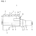
- FIG. 1 shows a highly schematic side view of a hybrid drive assembly 1 according to a first embodiment of the invention. Identical or functionally equivalent elements are denoted by the same reference numerals in all figures.
- the hybrid drive assembly 1 includes a diesel engine 3 of a commercial vehicle.
- the six cylinder heads 5 can be seen in the upper region of the diesel engine 3.
- the cylinders of the diesel engine 3 and the crankshaft 15, which is schematically represented by the dashed line 15, which marks the center line of the crankshaft or the crank mechanism, are surrounded by a crankcase 6, which is closed at the bottom with an oil pan 7.
- the oil pan 7 is in a conventional manner from a shallower Part 9 and a deeper part 8, in which the oil collects and in which an oil pump (not shown) is arranged.
- FIG. 1 also shows the clutch bell 11 as part of the transmission 13.
- a crankshaft stub 14 On the side facing away from the gearbox 13 of the diesel engine 3 protrudes from the crankcase 6, a crankshaft stub 14 on which the belt drive of the diesel engine 3 is arranged (in FIG. 1 not shown). Further, the output side of the transmission, a further crankshaft stub 12 is provided.
- the flywheel housing 11 umhaust in a conventional manner, a flywheel 19, which in the illustration of the FIG. 4 can be seen. Furthermore, in the area between the crankcase 6 and the flywheel 10, a gear drive 20 is provided, which is also provided by a housing, for. B. the flywheel housing 10, is umhaust.
- the gear drive 20 is a gear arrangement, which will be explained in more detail with reference to the following figures, which meshes with the crankshaft 15 and a camshaft and which is designed to drive at least one other auxiliary unit, if such is connected to the gear drive.
- the flywheel housing 10 has an output flange at the point identified by the reference numeral 4a.
- this output flange which forms an output interface, is used for coupling to an electric machine 4, which is screwed into the output flange.
- a gear 4b which is arranged on a stub shaft of the electric machine 4 (see also FIG. 4 ), with the wheel drive 20.
- the electric machine 4 extends according to the in the FIGS. 1 and 4 illustrated embodiment in the axial direction of the crankshaft 15 along the upper narrow portion 6a of the crankcase 6 and outside of the crankcase. 6
- FIG. 1 shown drive arrangement with the exception of the output of the diesel engine 3 connected electric machine 4 is already known from the prior art and need not be described in more detail here.
- the output interface in area 4a is not for attachment an accessory used, but for attachment of both motor and generator operable electric machine 4, so that the output interface can be used not only for power loss, but also for power supply.
- an existing internal combustion engine which has a power take-off, be extended to a hybrid drive.
- FIGS. 2 and 5 show in a schematic side view of another embodiment of the invention.
- the peculiarity of this embodiment lies in the fact that the electric machine 24 is in operative connection with the gear drive 20 at another attachment location 24a, on which a further output interface of the motor 3 is provided.
- an output flange is again provided in the upper area of the flywheel housing 10 on the side of the flywheel housing 10 facing the gearbox 13, with which the electric machine 24 is screwed.
- On the output flange in turn meshes on the stub shaft of the electric machine 4 rotatably arranged gear with a gear of the gear drive 20th
- the electric machine 24 extends on the output side in the axial direction of the crankshaft 15, such that the electric machine 24 extends at least partially over the transmission 13 of the vehicle. Further, the electric machine 24 is disposed at the height of the upper portion 6 a of the crankcase 6 and extends away from the diesel engine 3.
- FIG. 3 illustrates the attachment of the electric machine again in a view of the gear drive without flywheel housing.
- both previously described embodiments with the electrical machines 4 and 24 are shown simultaneously, wherein according to each embodiment, only either the electric machine 4 or the electric machine 24 is connected to the wheel gear 20 at the points shown (see. FIGS. 1 and 4 vs. Figures 2 and 5 ).
- the gear drive 20 consists of a gear arrangement with a gear 16 arranged on the crankshaft, which meshes with an intermediate gear 17, which in turn meshes with the camshaft drive gear 18.
- To connect the electric machine to the gear drive formed by this gear assembly 20 meshes in the coupled state of the electric machine rotatably mounted on a stub shaft of the electric machine gear 4b and 24b with the intermediate gear 17 and is coupled in this state with the gear drive 20.
- the electric machine 4 according to the first embodiment is arranged laterally from the crankshaft housing 6 in the upper region 6a of the crankshaft housing 6.
- the electric machine 24 according to the second embodiment is also arranged in the narrower region 6a of the crankshaft housing 6, but not laterally, but extending away from the crankshaft housing 6 on the transmission side.
- FIG. 4 is a detail in side view without transmission of the first embodiment shown.
- the electric machine 4 meshes at the output interface 4 a via a drive wheel 4 b of the hybrid module with the gear drive 20, in particular the intermediate gear 17 of the gear drive 20.
- the flywheel housing 10 housed flywheel 19.
- the reference numeral 4a further denotes the stub shaft of the electric machine 4, on which the drive gear 4b is arranged non-rotatably.
- FIG. 5 shows a detailed view in side view without gearbox of the second embodiment. It can be seen here that the electric machine 24 on the drive interface 24a likewise meshes with the gear drive 20 via a drive wheel 17 of the hybrid module.
- the reference numeral 24a further denotes the stub shaft of the electric machine 24 on which the drive gear 24b is arranged non-rotatably. In FIG. 5 the camshaft gear is covered by the drive gear 24b and therefore can not be seen
Landscapes
- Engineering & Computer Science (AREA)
- Chemical & Material Sciences (AREA)
- Combustion & Propulsion (AREA)
- Transportation (AREA)
- Mechanical Engineering (AREA)
- Hybrid Electric Vehicles (AREA)
Applications Claiming Priority (1)
| Application Number | Priority Date | Filing Date | Title |
|---|---|---|---|
| DE102014012397.9A DE102014012397A1 (de) | 2014-08-20 | 2014-08-20 | Hybridantriebsanordnung für ein Fahrzeug |
Publications (2)
| Publication Number | Publication Date |
|---|---|
| EP2990249A2 true EP2990249A2 (fr) | 2016-03-02 |
| EP2990249A3 EP2990249A3 (fr) | 2017-01-18 |
Family
ID=52946262
Family Applications (1)
| Application Number | Title | Priority Date | Filing Date |
|---|---|---|---|
| EP15001109.6A Withdrawn EP2990249A3 (fr) | 2014-08-20 | 2015-04-16 | Dispositif d'entraînement hybride pour un véhicule |
Country Status (2)
| Country | Link |
|---|---|
| EP (1) | EP2990249A3 (fr) |
| DE (1) | DE102014012397A1 (fr) |
Cited By (4)
| Publication number | Priority date | Publication date | Assignee | Title |
|---|---|---|---|---|
| EP3215382A1 (fr) * | 2014-11-03 | 2017-09-13 | Audi AG | Dispositif d'entraînement pour un véhicule automobile à fonctionnement hybride |
| WO2017194054A1 (fr) * | 2016-05-10 | 2017-11-16 | Schaeffler Technologies AG & Co. KG | Boîtier de module hybride servant à loger un moteur électrique et un embrayage de coupure, chaîne cinématique hybride et son procédé de montage |
| CN107618352A (zh) * | 2016-07-15 | 2018-01-23 | 通用汽车环球科技运作有限责任公司 | 混合动力传动系 |
| CN115823222A (zh) * | 2022-12-08 | 2023-03-21 | 中国重汽集团济南动力有限公司 | 发动机、混动系统和车辆 |
Families Citing this family (1)
| Publication number | Priority date | Publication date | Assignee | Title |
|---|---|---|---|---|
| DE102016007702B4 (de) | 2016-06-23 | 2026-02-26 | Man Truck & Bus Se | Nutzfahrzeug mit einem Parallel-Hybrid-Antriebsstrang |
Citations (6)
| Publication number | Priority date | Publication date | Assignee | Title |
|---|---|---|---|---|
| DE19841590A1 (de) * | 1998-09-11 | 2000-03-16 | Man Nutzfahrzeuge Ag | Anordnung und antriebsmäßige Anbindung von Nebenaggregaten an einer Brennkraftmaschine |
| US20060025260A1 (en) * | 2004-07-29 | 2006-02-02 | Donald Klemen | Powertrain including input disconnect and accessory drive system for an electrically variable transmission |
| US20120167857A1 (en) * | 2010-12-31 | 2012-07-05 | Barnes David M | Accessory drive configuration |
| WO2012092568A1 (fr) * | 2010-12-31 | 2012-07-05 | Cummins Inc. | Configuration de moteur d'entraînement d'accessoire |
| AT512035B1 (de) * | 2012-02-01 | 2013-05-15 | Avl List Gmbh | Antriebstrang für ein Fahrzeug |
| AT512710B1 (de) * | 2011-09-30 | 2014-06-15 | Steyr Motors Gmbh | Antriebseinheit mit einer elektrischen maschine |
Family Cites Families (6)
| Publication number | Priority date | Publication date | Assignee | Title |
|---|---|---|---|---|
| US6048288A (en) * | 1997-11-18 | 2000-04-11 | Toyota Jidosha Kabushiki Kaisha | Power train system for a vehicle and method for operating same |
| JP4173345B2 (ja) * | 2002-10-03 | 2008-10-29 | 本田技研工業株式会社 | 車両の駆動装置 |
| US8808124B2 (en) * | 2008-04-15 | 2014-08-19 | GM Global Technology Operations LLC | Belt alternator starter systems for hybrid vehicles |
| JP4637218B2 (ja) * | 2008-09-19 | 2011-02-23 | 本田技研工業株式会社 | 動力装置 |
| DE102012208488A1 (de) * | 2011-06-14 | 2012-12-20 | Schaeffler Technologies AG & Co. KG | Riementrieb und Verfahren zum Betrieb eines Nebenaggregats |
| ITTO20110924A1 (it) * | 2011-10-14 | 2013-04-15 | Merlo Project S R L Con Unico Socio | Macchina da lavoro ibrido elettro-idraulico |
-
2014
- 2014-08-20 DE DE102014012397.9A patent/DE102014012397A1/de not_active Ceased
-
2015
- 2015-04-16 EP EP15001109.6A patent/EP2990249A3/fr not_active Withdrawn
Patent Citations (6)
| Publication number | Priority date | Publication date | Assignee | Title |
|---|---|---|---|---|
| DE19841590A1 (de) * | 1998-09-11 | 2000-03-16 | Man Nutzfahrzeuge Ag | Anordnung und antriebsmäßige Anbindung von Nebenaggregaten an einer Brennkraftmaschine |
| US20060025260A1 (en) * | 2004-07-29 | 2006-02-02 | Donald Klemen | Powertrain including input disconnect and accessory drive system for an electrically variable transmission |
| US20120167857A1 (en) * | 2010-12-31 | 2012-07-05 | Barnes David M | Accessory drive configuration |
| WO2012092568A1 (fr) * | 2010-12-31 | 2012-07-05 | Cummins Inc. | Configuration de moteur d'entraînement d'accessoire |
| AT512710B1 (de) * | 2011-09-30 | 2014-06-15 | Steyr Motors Gmbh | Antriebseinheit mit einer elektrischen maschine |
| AT512035B1 (de) * | 2012-02-01 | 2013-05-15 | Avl List Gmbh | Antriebstrang für ein Fahrzeug |
Cited By (5)
| Publication number | Priority date | Publication date | Assignee | Title |
|---|---|---|---|---|
| EP3215382A1 (fr) * | 2014-11-03 | 2017-09-13 | Audi AG | Dispositif d'entraînement pour un véhicule automobile à fonctionnement hybride |
| WO2017194054A1 (fr) * | 2016-05-10 | 2017-11-16 | Schaeffler Technologies AG & Co. KG | Boîtier de module hybride servant à loger un moteur électrique et un embrayage de coupure, chaîne cinématique hybride et son procédé de montage |
| CN107618352A (zh) * | 2016-07-15 | 2018-01-23 | 通用汽车环球科技运作有限责任公司 | 混合动力传动系 |
| US10710449B2 (en) | 2016-07-15 | 2020-07-14 | GM Global Technology Operations LLC | Hybrid drivetrain |
| CN115823222A (zh) * | 2022-12-08 | 2023-03-21 | 中国重汽集团济南动力有限公司 | 发动机、混动系统和车辆 |
Also Published As
| Publication number | Publication date |
|---|---|
| EP2990249A3 (fr) | 2017-01-18 |
| DE102014012397A1 (de) | 2016-02-25 |
Similar Documents
| Publication | Publication Date | Title |
|---|---|---|
| DE102009050957B4 (de) | Mischhybrid | |
| DE102007011798A1 (de) | Zubehörantriebssystem und -verfahren für ein Riemen-Lichtmaschine-Anlasser-Elektrohybridfahrzeug | |
| DE102008043849A1 (de) | Mehrachsiges Hybrid-Antriebssystem für ein Fahrzeug | |
| DE102010047332A1 (de) | Hybridfahrzeugkonfiguration und Verfahren zum Umkonfigurieren einer Nichthybrid-Fahrzeugarchitektur als Hybrid-Fahrzeugarchitektur | |
| DE102011103239A1 (de) | Elektrofahrzeug-Antriebsstrang mit geringem Inhalt und verlängerter Reichweite | |
| DE102009023869A1 (de) | Kompressorsystem zur Druckluftversorgung eines Nutzfahrzeugs und Verfahren zum Betreiben eines Kompressorsystems | |
| DE102014012397A1 (de) | Hybridantriebsanordnung für ein Fahrzeug | |
| DE102011056431A1 (de) | Hybridantriebsstrang für Kraftfahrzeuge | |
| DE102019203722A1 (de) | Antriebsstrang für eine Arbeitsmaschine und Arbeitsmaschine | |
| EP3406474A1 (fr) | Dispositif d'entraînement hybride électro-hydraulique pour un véhicule automobile | |
| DE102019209986A1 (de) | Antriebsstrang für eine Arbeitsmaschine und Arbeitsmaschine | |
| DE102017223158A1 (de) | Elektrische Antriebsanordnung für Arbeitsmaschine | |
| EP2218603A1 (fr) | Entraînement hybride | |
| AT517965B1 (de) | Anordnung von Nebenaggregaten bei einer Brennkraftmaschine | |
| DE102016007702A1 (de) | Nutzfahrzeug mit einem Parallel-Hybrid-Antriebsstrang | |
| DE102007010343A1 (de) | Hybridfahrzeug mit Splitmotor | |
| DE102015112263A1 (de) | Antriebsstrang für ein Landfahrzeug | |
| DE102010018020A1 (de) | Kraftfahrzeug mit Hybridantrieb | |
| EP3951147A1 (fr) | Entraînement auxiliaire pour un moteur à combustion interne | |
| DE4137535C2 (de) | Maschinensatz zur Energieversorgung | |
| DE102005004737A1 (de) | Antriebssystem für ein Kraftfahrzeug mit Hybridantrieb | |
| DE102012023206A1 (de) | Zugmittelantrieb zum Antrieb von Nebenaggregaten in einem Kraftfahrzeug | |
| DE102018205818A1 (de) | Verfahren zum Betrieb eines Hybridelektrofahrzeugs | |
| DE102008044102A1 (de) | Hybridbaugruppe eines Hybridgetriebes eines Kraftfahrzeugs | |
| WO2008011958A1 (fr) | Véhicule automobile |
Legal Events
| Date | Code | Title | Description |
|---|---|---|---|
| PUAI | Public reference made under article 153(3) epc to a published international application that has entered the european phase |
Free format text: ORIGINAL CODE: 0009012 |
|
| AK | Designated contracting states |
Kind code of ref document: A2 Designated state(s): AL AT BE BG CH CY CZ DE DK EE ES FI FR GB GR HR HU IE IS IT LI LT LU LV MC MK MT NL NO PL PT RO RS SE SI SK SM TR |
|
| AX | Request for extension of the european patent |
Extension state: BA ME |
|
| PUAL | Search report despatched |
Free format text: ORIGINAL CODE: 0009013 |
|
| AK | Designated contracting states |
Kind code of ref document: A3 Designated state(s): AL AT BE BG CH CY CZ DE DK EE ES FI FR GB GR HR HU IE IS IT LI LT LU LV MC MK MT NL NO PL PT RO RS SE SI SK SM TR |
|
| AX | Request for extension of the european patent |
Extension state: BA ME |
|
| RIC1 | Information provided on ipc code assigned before grant |
Ipc: B60K 25/02 20060101ALI20161213BHEP Ipc: B60K 25/00 20060101ALI20161213BHEP Ipc: B60K 6/26 20071001ALI20161213BHEP Ipc: B60K 6/48 20071001AFI20161213BHEP Ipc: B60K 6/44 20071001ALI20161213BHEP Ipc: B60K 25/06 20060101ALI20161213BHEP Ipc: B60K 6/40 20071001ALI20161213BHEP Ipc: B60W 10/30 20060101ALI20161213BHEP |
|
| STAA | Information on the status of an ep patent application or granted ep patent |
Free format text: STATUS: REQUEST FOR EXAMINATION WAS MADE |
|
| 17P | Request for examination filed |
Effective date: 20170717 |
|
| RAP1 | Party data changed (applicant data changed or rights of an application transferred) |
Owner name: MAN TRUCK & BUS SE |
|
| STAA | Information on the status of an ep patent application or granted ep patent |
Free format text: STATUS: EXAMINATION IS IN PROGRESS |
|
| 17Q | First examination report despatched |
Effective date: 20190910 |
|
| GRAP | Despatch of communication of intention to grant a patent |
Free format text: ORIGINAL CODE: EPIDOSNIGR1 |
|
| STAA | Information on the status of an ep patent application or granted ep patent |
Free format text: STATUS: GRANT OF PATENT IS INTENDED |
|
| INTG | Intention to grant announced |
Effective date: 20231117 |
|
| STAA | Information on the status of an ep patent application or granted ep patent |
Free format text: STATUS: THE APPLICATION IS DEEMED TO BE WITHDRAWN |
|
| 18D | Application deemed to be withdrawn |
Effective date: 20240319 |