EP2990375A2 - Mikromechanische vorrichtung mit elektromagnetischer betätigung - Google Patents
Mikromechanische vorrichtung mit elektromagnetischer betätigung Download PDFInfo
- Publication number
- EP2990375A2 EP2990375A2 EP15182767.2A EP15182767A EP2990375A2 EP 2990375 A2 EP2990375 A2 EP 2990375A2 EP 15182767 A EP15182767 A EP 15182767A EP 2990375 A2 EP2990375 A2 EP 2990375A2
- Authority
- EP
- European Patent Office
- Prior art keywords
- rotor
- axis
- support
- active element
- circle
- Prior art date
- Legal status (The legal status is an assumption and is not a legal conclusion. Google has not performed a legal analysis and makes no representation as to the accuracy of the status listed.)
- Granted
Links
Images


Classifications
-
- B—PERFORMING OPERATIONS; TRANSPORTING
- B81—MICROSTRUCTURAL TECHNOLOGY
- B81B—MICROSTRUCTURAL DEVICES OR SYSTEMS, e.g. MICROMECHANICAL DEVICES
- B81B3/00—Devices comprising flexible or deformable elements, e.g. comprising elastic tongues or membranes
- B81B3/0018—Structures acting upon the moving or flexible element for transforming energy into mechanical movement or vice versa, i.e. actuators, sensors, generators
- B81B3/0021—Transducers for transforming electrical into mechanical energy or vice versa
-
- G—PHYSICS
- G02—OPTICS
- G02B—OPTICAL ELEMENTS, SYSTEMS OR APPARATUS
- G02B26/00—Optical devices or arrangements for the control of light using movable or deformable optical elements
- G02B26/08—Optical devices or arrangements for the control of light using movable or deformable optical elements for controlling the direction of light
- G02B26/0816—Optical devices or arrangements for the control of light using movable or deformable optical elements for controlling the direction of light by means of one or more reflecting elements
- G02B26/0833—Optical devices or arrangements for the control of light using movable or deformable optical elements for controlling the direction of light by means of one or more reflecting elements the reflecting element being a micromechanical device, e.g. a MEMS mirror, DMD
- G02B26/085—Optical devices or arrangements for the control of light using movable or deformable optical elements for controlling the direction of light by means of one or more reflecting elements the reflecting element being a micromechanical device, e.g. a MEMS mirror, DMD the reflecting means being moved or deformed by electromagnetic means
-
- H—ELECTRICITY
- H02—GENERATION; CONVERSION OR DISTRIBUTION OF ELECTRIC POWER
- H02K—DYNAMO-ELECTRIC MACHINES
- H02K33/00—Motors with reciprocating, oscillating or vibrating magnet, armature or coil system
- H02K33/18—Motors with reciprocating, oscillating or vibrating magnet, armature or coil system with coil systems moving upon intermittent or reversed energisation thereof by interaction with a fixed field system, e.g. permanent magnets
-
- H—ELECTRICITY
- H02—GENERATION; CONVERSION OR DISTRIBUTION OF ELECTRIC POWER
- H02K—DYNAMO-ELECTRIC MACHINES
- H02K41/00—Propulsion systems in which a rigid body is moved along a path due to dynamo-electric interaction between the body and a magnetic field travelling along the path
- H02K41/02—Linear motors; Sectional motors
- H02K41/03—Synchronous motors; Motors moving step by step; Reluctance motors
- H02K41/031—Synchronous motors; Motors moving step by step; Reluctance motors of the permanent magnet type
-
- B—PERFORMING OPERATIONS; TRANSPORTING
- B81—MICROSTRUCTURAL TECHNOLOGY
- B81B—MICROSTRUCTURAL DEVICES OR SYSTEMS, e.g. MICROMECHANICAL DEVICES
- B81B2201/00—Specific applications of microelectromechanical systems
- B81B2201/04—Optical MEMS
- B81B2201/042—Micromirrors, not used as optical switches
-
- B—PERFORMING OPERATIONS; TRANSPORTING
- B81—MICROSTRUCTURAL TECHNOLOGY
- B81B—MICROSTRUCTURAL DEVICES OR SYSTEMS, e.g. MICROMECHANICAL DEVICES
- B81B2203/00—Basic microelectromechanical structures
- B81B2203/05—Type of movement
- B81B2203/058—Rotation out of a plane parallel to the substrate
Definitions
- the present invention relates to electromechanical microsystems, better known by the name MEMS of the English microelectromechanical systems. It relates more specifically to a micromechanical device comprising a movable active element according to at least one axis of rotation, and electromagnetic type actuating means.
- micromechanical devices are generally optical devices, whose active element consists of a movable mirror according to at least one axis of rotation, connected to a support with the aid of two torsionally elastic beams defining said axis of rotation. They are conventionally manufactured from silicon wafers by photolithography processes well known to those skilled in the art.
- these devices In the static mode, they generally form optical switches for switching a light beam between fixed angular positions. In dynamic mode, the mirror sweeps a light beam over a determined angular space, and the corresponding micromechanical devices are equipped, in particular, optical spectrometers, printers, medical imaging devices or light sensors.
- micromechanical devices of static or dynamic type, electromagnetically actuated using a rotor, formed of at least one conductive turn mounted integral with the movable element, and a stator , comprising two poles separated by an air gap in which the rotor takes place.
- a rotor formed of at least one conductive turn mounted integral with the movable element, and a stator , comprising two poles separated by an air gap in which the rotor takes place.
- the intensity of the Laplace force is proportional to the intensity of the B field.
- the magnetic induction is all the weaker inside the gap, since the latter is wide. This is the case, for example, of the micromechanical device described by the document WO2009 / 147304 .
- the poles, formed of magnetized layers, define an air gap in which takes place the movable mirror - rotor assembly.
- the magnetic field B prevailing inside the air gap acts globally on the entire conducting coil, between two poles apart from their magnetic polarization. It emerges that the intensity of the field B in the gap is small and of poorly defined orientation, and does not allow the application of significant torsional forces.
- the movable mirror is connected to a first frame by means of two torsion beams defining a first axis of rotation, which is itself connected to a support by means of two other torsion beams perpendicular to the first and defining a second rotation axis.
- the application of a magnetic field to the assembly of a micromechanical structure comprising one or more mirrors involves being attentive to the flow direction of the current in the different rotor portions.
- the direction of the current in the two rotor portions parallel to the axis of rotation of the mirror must be opposite, under penalty of applying forces F balancing and zero torque.
- the geometry of the rotors is, for the most part, limited to that of a rectangular turn, of the type disclosed in the document WO2009 / 147304 .
- the strands entering and leaving the rotor necessarily pass through the same torsion beam and their width is limited to about a quarter of that of the beam to avoid any short circuit.
- This geometric constraint has the effect of restricting the maximum intensity of the current I flowing in the rotor, and, consequently, the force F applied to the mirror.
- the object of the present invention is to overcome the aforementioned drawbacks, by proposing a micromechanical device with electromagnetic actuation, capable of applying significant torsional forces along two axes of rotation, thanks to a strong magnetic field and well-defined orientation. More specifically, the invention relates to a micromechanical device with electromagnetic actuation comprising a support, an active element mounted rotatably on the support along a first axis AA, a first rotor formed of at least one conductive electrical line, mounted integral with rotation of the active element, and a first stator comprising at least two opposite magnetic poles separated by an air gap in which the rotor is partially located.
- the rotor comprises a first segment separated from the active element by a first empty space, and the stator is positioned inside the support so as to receive the segment in its gap, its poles being disposed of and other segment, one of them taking place inside the first empty space.
- the magnetic field B exerted by the stator is not present or acting, overall on the rotor assembly, but locally at a portion thereof.
- the confinement of the magnetic field B at a segment of the rotor makes it possible, first of all, to increase its local intensity and, consequently, the actuating force F of the active element, without increasing the current I flowing in the conductive coil.
- the effectiveness of the device according to the invention is greatly improved.
- the local action of a first stator at a rotor integral with the active element makes possible the local action of a second rotor, in a direction perpendicular to the first.
- the confinement of the magnetic field B 1 locally at a rotor segment allows a second magnetic field B 2 neighbor to act locally without being superimposed on the first.
- active element 10 consists of a network, a lens, or any other optically active component.
- the assembly is essentially planar, and manufactured, for example, in silicon, using micro-manufacturing techniques well known to those skilled in the art.
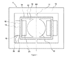
- a frame 14 is mounted integral in rotation with the active element 10, at the junction between the torsion beams 11 and the active element 10.
- the frame 14 can be mounted directly on the torsion beams 11, or on the active element 10 itself.
- the frame 14 has two sides 15 parallel and symmetrical with respect to the axis AA, each of them being separated from the active element 10 by a blank space 16 whose function will appear later.
- the assembly consisting of the mirror 10, the support 12 and the frame 14, is made in one piece from a silicon wafer, during a single lithography operation.
- a rotor 17, formed of a conductive line for conducting a current I, is mounted integral with the frame 14 and conforms to its geometry.
- said rotor conventionally forms a rectangular turn entering and exiting through one of the torsion beams 11. It consists, for example, of a metal track deposited on the frame 14, a metal coil bonded to said frame 14, or any Another winding capable of conducting a current I.
- the rotor 17 is mounted on the front face of the frame 14, but can be indifferently attached to its rear face, depending on the structural or functional constraints of the device 1.
- the two rotor segments 18 carried by the sides 15 of the frame 14, form two portions of conductor parallel to the axis AA of rotation of the active element 10, symmetrical with respect thereto, and clear of material from all parts.
- the micromechanical device 1 describes with regard to figures 1 and 2 , further comprises a pair of stators 19 each provided with two opposite magnetic poles, respectively 20, 21, separated by an air gap 22 traversed by a magnetic field B.
- Said stators 19 are dimensioned and arranged to take place inside the support 12, symmetrically with respect to the axis AA, and to receive said rotor segments 18 in their respective gap 22.
- the opposite poles 20 , 21 are themselves adapted in size and shape to take place, respectively, on either side of the segments 18, one of them being disposed in the space 16.
- the air gaps 22 form, as for them, a housing large enough to receive the segments 18, while being narrow enough to confine the maximum magnetic field B and keep it constant in their volume.
- stator 19 whose structure is particularly adapted to the micromechanical device 1 according to the invention.
- Said stators 19 comprise at least one permanent magnet 40, attached to a structure of ferromagnetic material 41, which comprises one or more elements arranged so as to form, with the magnet 40, a U.
- the operating principle of the micromechanical device 1 according to the invention is identical to that of a device according to the state of the art.
- a force F acts on the segments 18, perpendicularly to the plane of the device, actuating the active element 10 in rotation about the axis AA.
- its structural characteristics confer significant advantages in terms of performance and efficiency.
- the magnetic field B acts locally on the rotor segments 18 which they are perpendicular, and not globally on the whole of it.
- the small spacing between the poles 20, 21 makes it possible to obtain a high magnetic field in the gaps 22, making it possible to actuate the active element 10 in rotation with a low current I.
- the magnetic field lines B in the gap 22 have a well-defined orientation, perpendicular to the segments 18, hence the absence of losses due to a lack of perpendicularity between B and I. It follows that the micromechanical device 1 is significantly higher efficiency than devices of the same type belonging to the state of the art. It is further noted that the confinement of the magnetic field B in the air gaps 22 makes the micromechanical device 1 little sensitive to possible external magnetic disturbances, unlike existing devices.
- FIG. 3 representing a micromechanical device according to the invention in which the geometry of the rotor 17 is optimized to conduct a current of maximum intensity.
- the rotor is formed of a conductive line drawing an 8 whose incoming and outgoing strands pass respectively through one and the other torsion beam 11.
- This arrangement is made possible by the local positioning of the stators 19, whereby the flow direction of the current in a segment 18 is independent of the flow direction of the current in the other segment 18 from the point of view of the application of the force F. It allows to double the width of the conductive line forming the rotor 17 with respect to the state of the art, and increase all the intensity of the current I and the force F resulting therefrom.
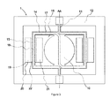
- FIG. figure 4 Said device, referenced as a whole 2, differs from the device described with regard to Figures 1 to 3 , in that it comprises a second frame 24, interposed between the frame 14 and the support 12.
- the frame 24 is rotatably mounted on the support 12 along an axis BB, perpendicular to the axis AA, via two torsion beams 23.
- the active element 10 and the frame 14 are, in turn, rotatably mounted along the axis AA indirectly on the support 12, by means of torsion beams 11 connected to the frame 24 itself mounted on the support 12.
- the frame 24 has two sides 25 parallel and symmetrical with respect to the axis BB, the sides 25 being, by construction, free of material on either side.
- the frame 24 carries a second rotor 27, formed of at least one conductive line, mounted according to its geometry.
- the rotor segments 28 integral with the sides 25 form, similarly to the segments 18, conductor portions parallel to the axis BB, active for the actuation of the device 1.
- the micromechanical device 2 further comprises two additional pairs of stators 29 dimensioned and arranged to take place inside the support 12, symmetrically with respect to the axes AA and BB, and to receive said rotor segments 28 in their respective gap 32.
- the poles 30, 31 of the stators 29, take place on either side of the segments 28, and their gap 32 is dimensioned to housing the rotor segments 28 while confining the magnetic field to a maximum B.
- This micromechanical device 2 is identical to the previous one.
- the confinement of the magnetic field B around the rotor segments 18, 28 provides the same advantages as those already mentioned, namely the energy efficiency and the resistance of the device to external magnetic disturbances. It allows, in addition, a substantial performance gain, namely the actuation of the active element along a second axis of rotation BB. Indeed, the local action of the magnetic field B makes it possible to have the stators close to each other, without disturbance or interaction between them. This characteristic confers great flexibility in the structure of the micromechanical device according to the invention.
- the stators can be distributed perpendicularly to each other, so as to actuate the mirror 10 along two axes of rotation, without loss by a factor of 0.7, as is the case for a device comprising a single stator acting on one or more rotors.
- This profit is cumulative with the previous ones, because the aforementioned advantages remain valid according to the two axes of rotation.
- FIG 5 illustrates a simplified embodiment of a micromechanical device according to the invention, movable along an axis of rotation.
- the micromechanical device represented in figure 5 and referenced as a whole 3, is distinguished from the device 1, in that the frame 14, integral with the active element 10, extends on one side only of the axis AA.
- the rotor 17 has only one segment 18 parallel to the axis AA and separated from the active element 10 by a space 16.
- a single stator 19 takes place inside the support 12 to actuate the active element 10 in rotation, the segment 18 being disposed in the air gap 22 of the stator 19.
- the operating mode of this device is similar to that of the device described with respect to figures 1 and 2 but it is of simplified structure. Due to its small size, and in particular the very low weight of the active element 10 in comparison with the electromagnetic actuating force F, the asymmetry of the system poses no functional problem.
- the device 1 comprises a first rigid frame 14, integral with the active element 10, and a second rigid frame 24, rotatably mounted on the support 12 along the axis BB by means of torsion beams 23.
- the active element 10 is itself mounted integral with the second rigid frame 24 by means of torsion beams 11.
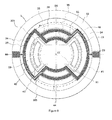
- the assembly is distinguished from the device described with respect to the figure 4 , in that the frames 14 and 24 are not rectangular, but consist of circular portions interconnected by radial branches.
- the first frame 14 comprises two first circle portions 15 of radius R, symmetrical about the axis AA, connected to the active element 10 by four radial branches 105.
- the second frame 24 comprises two seconds circle portions 25 of radius R, arranged symmetrically with respect to the axis BB.
- the first and second circle portions 15, 25, being the active portions of the frames 14 and 24, are located on the same virtual circle of radius R and center the intersection of the axes AA and BB.
- the second frame 24 further comprises two third portions of circle 35 of radius r less than R, concentric with the second circle portions 25, and connected thereto by radial branches 205. It finally comprises two fourth circle portions 45 of radius R greater than R, concentric to the first circle portions 15 and connected to the second and third circle portions 25 and 35, by the radial branches 205.
- the torsion beams 11 connect the active element 10 to the third portions of the circle 35, while that the torsion beams 23 connect the fourth circle portions 45 to the support 12, so that the active element 10 is mounted on the support 12 indirectly via the second frame 24.
- the first rotor 17, mounted on the rear face of the device 1, is formed of a conductive line circulating on the first active portions of the circle 15, via the torsion beams 23 and 11, the circle portions 35 and 45, and the branches radial members 105 and 205.
- Said rotor 17 draws an 8 on the rear face of the frame assembly 14 - active element 10, so that current I traverses the circle portions 15 in opposite directions of rotation, thus forming two rotor segments 18 arcuate, symmetrical with respect to the axis AA, electromagnetically active.
- the second rotor 27, mounted on the front face of the device 1, is also formed of a conductive line circulating on the second circle portions 25, via the torsion beams 23, the circle portions 35 and 45, and the radial branches 205
- the circuit formed by the rotor 27 is optimized to maximize the intensity of the current I flowing over the active circle portions 25, with the constraint that its direction of rotation in the circle portions 25 is opposite. The justification for this constraint will appear later.
- the rotor segments 28 carried by the circle portions 25 are symmetrical with respect to the BB axis and electromagnetically active.
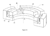
- the device 1 illustrated with regard to figures 8 and 9 further comprises a single stator 19 of circular shape, shown in section in figure 10 .
- Said stator 19 is conventionally formed of a permanent magnet 40, attached to a structure made of ferromagnetic material 41, which comprises a lower piece 42 and an upper piece 43, the assembly forming a circular block, of axis CC perpendicular to the formed plane. by axes AA and BB.
- the stator 19 thus constituted comprises four air gaps 44, in an arc, forming a virtual circle of radius R in the plane parallel to the axes AA and BB, and a U in a plane parallel to the axis CC.
- Said air gaps 44 are arranged and dimensioned to receive the portions of circles 15 and 25 with a minimum of play, and are separated from each other by trenches 46.
- the stator 19 because of its circular shape, is a great compactness. It is manufactured easily and inexpensively, by conventional filming techniques. In addition, its circular geometry ensures excellent homogeneity of the magnetic field B inside air gaps 44, and low losses.
- the first and second circle portions 15 and 25 take place inside the air gaps 44, while the radial branches 105 and 205 are deployed inside the trenches 46.
- the circular shape of the stator 19 involves the alignment according to a circle of radius R of the circle portions 15 and 25 as mentioned before.
- the frames 14 and 24 are actuated by the circulation of a current I, respectively in the rotors 17 and 27, according to the Laplace principle.
- the confinement of the magnetic field inside the air gaps 44 provides the advantages already mentioned above.
- micromechanical device with electromagnetic actuation, movable along one or two axes of rotation.
- present invention is not limited to the embodiments described above, but extends to all variants within the scope of those skilled in the art, falling within the scope of the claims below.
- the micromechanical device according to the invention is very flexible in its structure.
- the number and the positioning of the stators inside the support can vary according to the final application, without departing from the scope of the invention defined by the appended claims.
Landscapes
- Physics & Mathematics (AREA)
- Engineering & Computer Science (AREA)
- Electromagnetism (AREA)
- Power Engineering (AREA)
- Chemical & Material Sciences (AREA)
- General Physics & Mathematics (AREA)
- Combustion & Propulsion (AREA)
- Optics & Photonics (AREA)
- Analytical Chemistry (AREA)
- Computer Hardware Design (AREA)
- Microelectronics & Electronic Packaging (AREA)
- Micromachines (AREA)
- Reciprocating, Oscillating Or Vibrating Motors (AREA)
Applications Claiming Priority (1)
| Application Number | Priority Date | Filing Date | Title |
|---|---|---|---|
| CH01315/14A CH710072A2 (fr) | 2014-09-01 | 2014-09-01 | Dispositif micromécanique à actionnement électromagnetique. |
Publications (3)
| Publication Number | Publication Date |
|---|---|
| EP2990375A2 true EP2990375A2 (de) | 2016-03-02 |
| EP2990375A3 EP2990375A3 (de) | 2016-06-08 |
| EP2990375B1 EP2990375B1 (de) | 2017-08-16 |
Family
ID=54337090
Family Applications (1)
| Application Number | Title | Priority Date | Filing Date |
|---|---|---|---|
| EP15182767.2A Active EP2990375B1 (de) | 2014-09-01 | 2015-08-27 | Mikromechanische vorrichtung mit elektromagnetischer betätigung |
Country Status (2)
| Country | Link |
|---|---|
| EP (1) | EP2990375B1 (de) |
| CH (1) | CH710072A2 (de) |
Cited By (5)
| Publication number | Priority date | Publication date | Assignee | Title |
|---|---|---|---|---|
| CN109843787A (zh) * | 2016-10-19 | 2019-06-04 | 罗伯特·博世有限公司 | 微机械构件和用于微机械构件的制造方法 |
| EP3647261A1 (de) * | 2018-10-31 | 2020-05-06 | Sercalo Microtechnology Ltd. | Mikromechanische vorrichtung mit lokaler elektromagnetischer betätigung |
| EP3598622A4 (de) * | 2017-03-13 | 2021-01-06 | Pioneer Corporation | Antriebsvorrichtung und abstandsmessvorrichtung |
| EP3690514A4 (de) * | 2017-09-27 | 2021-07-07 | The Nippon Signal Co., Ltd. | Aktuator |
| CN113608347A (zh) * | 2020-05-04 | 2021-11-05 | 通用汽车环球科技运作有限责任公司 | 实现平面mems反射镜的优化电流路径 |
Families Citing this family (1)
| Publication number | Priority date | Publication date | Assignee | Title |
|---|---|---|---|---|
| CH715874A1 (fr) * | 2019-02-26 | 2020-08-31 | Sercalo Microtechnology Ltd | Dispositif micromécanique à bobine. |
Citations (2)
| Publication number | Priority date | Publication date | Assignee | Title |
|---|---|---|---|---|
| US20080143196A1 (en) | 2004-05-14 | 2008-06-19 | Microvision Inc. | MEMS scanner driven by two or more signal lines |
| WO2009147304A1 (fr) | 2008-06-02 | 2009-12-10 | Lemoptix Sa | Micromiroir a actionnement electromagnetique |
Family Cites Families (2)
| Publication number | Priority date | Publication date | Assignee | Title |
|---|---|---|---|---|
| JP4968760B1 (ja) * | 2011-11-01 | 2012-07-04 | パイオニア株式会社 | アクチュエータ |
| WO2013168264A1 (ja) * | 2012-05-10 | 2013-11-14 | パイオニア株式会社 | 駆動装置 |
-
2014
- 2014-09-01 CH CH01315/14A patent/CH710072A2/fr not_active Application Discontinuation
-
2015
- 2015-08-27 EP EP15182767.2A patent/EP2990375B1/de active Active
Patent Citations (2)
| Publication number | Priority date | Publication date | Assignee | Title |
|---|---|---|---|---|
| US20080143196A1 (en) | 2004-05-14 | 2008-06-19 | Microvision Inc. | MEMS scanner driven by two or more signal lines |
| WO2009147304A1 (fr) | 2008-06-02 | 2009-12-10 | Lemoptix Sa | Micromiroir a actionnement electromagnetique |
Cited By (10)
| Publication number | Priority date | Publication date | Assignee | Title |
|---|---|---|---|---|
| CN109843787A (zh) * | 2016-10-19 | 2019-06-04 | 罗伯特·博世有限公司 | 微机械构件和用于微机械构件的制造方法 |
| CN109843787B (zh) * | 2016-10-19 | 2022-10-04 | 罗伯特·博世有限公司 | 微机械构件和用于微机械构件的制造方法 |
| EP3598622A4 (de) * | 2017-03-13 | 2021-01-06 | Pioneer Corporation | Antriebsvorrichtung und abstandsmessvorrichtung |
| US11555892B2 (en) | 2017-03-13 | 2023-01-17 | Pioneer Corporation | Drive device and distance measurement apparatus |
| EP4220917A1 (de) * | 2017-03-13 | 2023-08-02 | Pioneer Corporation | Antriebsvorrichtung und abstandsmessvorrichtung |
| EP3690514A4 (de) * | 2017-09-27 | 2021-07-07 | The Nippon Signal Co., Ltd. | Aktuator |
| EP3647261A1 (de) * | 2018-10-31 | 2020-05-06 | Sercalo Microtechnology Ltd. | Mikromechanische vorrichtung mit lokaler elektromagnetischer betätigung |
| CH715505A1 (fr) * | 2018-10-31 | 2020-05-15 | Sercalo Microtechnology Ltd | Dispositif micromécanique à actionnement électromagnétique local. |
| CN113608347A (zh) * | 2020-05-04 | 2021-11-05 | 通用汽车环球科技运作有限责任公司 | 实现平面mems反射镜的优化电流路径 |
| CN113608347B (zh) * | 2020-05-04 | 2023-09-08 | 通用汽车环球科技运作有限责任公司 | 实现平面mems反射镜的优化电流路径 |
Also Published As
| Publication number | Publication date |
|---|---|
| EP2990375A3 (de) | 2016-06-08 |
| CH710072A2 (fr) | 2016-03-15 |
| EP2990375B1 (de) | 2017-08-16 |
Similar Documents
| Publication | Publication Date | Title |
|---|---|---|
| EP2990375B1 (de) | Mikromechanische vorrichtung mit elektromagnetischer betätigung | |
| EP0616665B1 (de) | Magnetische lagervorrichtung und mechanischer anschlag zum positionieren einesdrehkörpers gegenüber einem stator | |
| EP0113267B1 (de) | Elektromechanischer Umformer mit mehreren Freiheitsgraden | |
| CA3106491C (fr) | Dispositif roulant adapte a rouler sur un sol | |
| FR2797477A1 (fr) | Palier magnetique du type rotule pour corps basculant | |
| EP0613594B1 (de) | Länglicher Drehmomentmotor und denselben aufweisende steuervorrichtung der winkelabweichung | |
| FR2797478A1 (fr) | Palier magnetique de centrage a commande en basculement de grande amplitude | |
| EP2887156B1 (de) | Einstellvorrichtung | |
| FR2490048A1 (fr) | Unite de commande de tete video | |
| EP0458056B1 (de) | Elektromagnetischer Motor | |
| EP4011769A1 (de) | Antriebsvorrichtung für ein drehflügelflugzeug mit senkrechtem start und senkrechter landung und luftfahrzeug, das mit einer solchen antriebsvorrichtung ausgestattet ist | |
| EP3944027A1 (de) | Tragbares gerät, insbesondere armbanduhr, das mit einer stromquellevorrichtung mit einem elektromechanischen wandler ausgestattet ist | |
| EP2407832A1 (de) | Uhrwerk einer Uhr | |
| FR2785734A1 (fr) | Dispositif magnetique pour corps tournant et ensemble mecanique le comportant | |
| FR2713292A1 (fr) | Dispositif à palier magnétique pour le basculement d'un corps tournant par rapport à un corps statorique. | |
| WO2017072422A1 (fr) | Dispositif d'assistance motorise, notamment au pédalage, et cycle associe | |
| FR3032570A1 (fr) | Moteur electrique pivotant | |
| EP3702321B1 (de) | Mikromechanische vorrichtung mit spule | |
| EP1381904A1 (de) | Optischer multipositionsschalter | |
| EP0783202A1 (de) | Beschleuniger für Linearantrieb | |
| FR3161464A1 (fr) | Dispositif de freinage a champ magnetique tournant, roue freinee et aeronef correspondant. | |
| FR3032060A1 (fr) | Actionneur et positionneur comportant un tel actionneur | |
| BE1023490B1 (fr) | Moteur électrique | |
| EP4472888A1 (de) | Antriebsvorrichtung für ein drehflügelflugzeug mit senkrechtstart und -landung und mit solch einer antriebsvorrichtung ausgestattetes flugzeug | |
| FR3146660A1 (fr) | Dispositif de contrôle de vitesse angulaire d'un engin spatial et engin spatial correspondant. |
Legal Events
| Date | Code | Title | Description |
|---|---|---|---|
| PUAI | Public reference made under article 153(3) epc to a published international application that has entered the european phase |
Free format text: ORIGINAL CODE: 0009012 |
|
| AK | Designated contracting states |
Kind code of ref document: A2 Designated state(s): AL AT BE BG CH CY CZ DE DK EE ES FI FR GB GR HR HU IE IS IT LI LT LU LV MC MK MT NL NO PL PT RO RS SE SI SK SM TR |
|
| AX | Request for extension of the european patent |
Extension state: BA ME |
|
| PUAL | Search report despatched |
Free format text: ORIGINAL CODE: 0009013 |
|
| AK | Designated contracting states |
Kind code of ref document: A3 Designated state(s): AL AT BE BG CH CY CZ DE DK EE ES FI FR GB GR HR HU IE IS IT LI LT LU LV MC MK MT NL NO PL PT RO RS SE SI SK SM TR |
|
| AX | Request for extension of the european patent |
Extension state: BA ME |
|
| RIC1 | Information provided on ipc code assigned before grant |
Ipc: B81B 3/00 20060101AFI20160503BHEP Ipc: H02K 19/10 20060101ALI20160503BHEP Ipc: G02B 26/08 20060101ALI20160503BHEP |
|
| STAA | Information on the status of an ep patent application or granted ep patent |
Free format text: STATUS: REQUEST FOR EXAMINATION WAS MADE |
|
| 17P | Request for examination filed |
Effective date: 20161207 |
|
| RBV | Designated contracting states (corrected) |
Designated state(s): AL AT BE BG CH CY CZ DE DK EE ES FI FR GB GR HR HU IE IS IT LI LT LU LV MC MK MT NL NO PL PT RO RS SE SI SK SM TR |
|
| GRAP | Despatch of communication of intention to grant a patent |
Free format text: ORIGINAL CODE: EPIDOSNIGR1 |
|
| STAA | Information on the status of an ep patent application or granted ep patent |
Free format text: STATUS: GRANT OF PATENT IS INTENDED |
|
| INTG | Intention to grant announced |
Effective date: 20170310 |
|
| GRAS | Grant fee paid |
Free format text: ORIGINAL CODE: EPIDOSNIGR3 |
|
| GRAA | (expected) grant |
Free format text: ORIGINAL CODE: 0009210 |
|
| STAA | Information on the status of an ep patent application or granted ep patent |
Free format text: STATUS: THE PATENT HAS BEEN GRANTED |
|
| AK | Designated contracting states |
Kind code of ref document: B1 Designated state(s): AL AT BE BG CH CY CZ DE DK EE ES FI FR GB GR HR HU IE IS IT LI LT LU LV MC MK MT NL NO PL PT RO RS SE SI SK SM TR |
|
| REG | Reference to a national code |
Ref country code: GB Ref legal event code: FG4D Free format text: NOT ENGLISH |
|
| REG | Reference to a national code |
Ref country code: FR Ref legal event code: PLFP Year of fee payment: 3 |
|
| REG | Reference to a national code |
Ref country code: CH Ref legal event code: EP |
|
| REG | Reference to a national code |
Ref country code: IE Ref legal event code: FG4D Free format text: LANGUAGE OF EP DOCUMENT: FRENCH |
|
| REG | Reference to a national code |
Ref country code: AT Ref legal event code: REF Ref document number: 918844 Country of ref document: AT Kind code of ref document: T Effective date: 20170915 |
|
| REG | Reference to a national code |
Ref country code: DE Ref legal event code: R096 Ref document number: 602015004118 Country of ref document: DE |
|
| REG | Reference to a national code |
Ref country code: NL Ref legal event code: MP Effective date: 20170816 |
|
| REG | Reference to a national code |
Ref country code: LT Ref legal event code: MG4D |
|
| REG | Reference to a national code |
Ref country code: AT Ref legal event code: MK05 Ref document number: 918844 Country of ref document: AT Kind code of ref document: T Effective date: 20170816 |
|
| PG25 | Lapsed in a contracting state [announced via postgrant information from national office to epo] |
Ref country code: AT Free format text: LAPSE BECAUSE OF FAILURE TO SUBMIT A TRANSLATION OF THE DESCRIPTION OR TO PAY THE FEE WITHIN THE PRESCRIBED TIME-LIMIT Effective date: 20170816 Ref country code: FI Free format text: LAPSE BECAUSE OF FAILURE TO SUBMIT A TRANSLATION OF THE DESCRIPTION OR TO PAY THE FEE WITHIN THE PRESCRIBED TIME-LIMIT Effective date: 20170816 Ref country code: LT Free format text: LAPSE BECAUSE OF FAILURE TO SUBMIT A TRANSLATION OF THE DESCRIPTION OR TO PAY THE FEE WITHIN THE PRESCRIBED TIME-LIMIT Effective date: 20170816 Ref country code: SE Free format text: LAPSE BECAUSE OF FAILURE TO SUBMIT A TRANSLATION OF THE DESCRIPTION OR TO PAY THE FEE WITHIN THE PRESCRIBED TIME-LIMIT Effective date: 20170816 Ref country code: NO Free format text: LAPSE BECAUSE OF FAILURE TO SUBMIT A TRANSLATION OF THE DESCRIPTION OR TO PAY THE FEE WITHIN THE PRESCRIBED TIME-LIMIT Effective date: 20171116 Ref country code: NL Free format text: LAPSE BECAUSE OF FAILURE TO SUBMIT A TRANSLATION OF THE DESCRIPTION OR TO PAY THE FEE WITHIN THE PRESCRIBED TIME-LIMIT Effective date: 20170816 |
|
| PG25 | Lapsed in a contracting state [announced via postgrant information from national office to epo] |
Ref country code: PL Free format text: LAPSE BECAUSE OF FAILURE TO SUBMIT A TRANSLATION OF THE DESCRIPTION OR TO PAY THE FEE WITHIN THE PRESCRIBED TIME-LIMIT Effective date: 20170816 Ref country code: BG Free format text: LAPSE BECAUSE OF FAILURE TO SUBMIT A TRANSLATION OF THE DESCRIPTION OR TO PAY THE FEE WITHIN THE PRESCRIBED TIME-LIMIT Effective date: 20171116 Ref country code: LV Free format text: LAPSE BECAUSE OF FAILURE TO SUBMIT A TRANSLATION OF THE DESCRIPTION OR TO PAY THE FEE WITHIN THE PRESCRIBED TIME-LIMIT Effective date: 20170816 Ref country code: RS Free format text: LAPSE BECAUSE OF FAILURE TO SUBMIT A TRANSLATION OF THE DESCRIPTION OR TO PAY THE FEE WITHIN THE PRESCRIBED TIME-LIMIT Effective date: 20170816 Ref country code: IS Free format text: LAPSE BECAUSE OF FAILURE TO SUBMIT A TRANSLATION OF THE DESCRIPTION OR TO PAY THE FEE WITHIN THE PRESCRIBED TIME-LIMIT Effective date: 20171216 Ref country code: GR Free format text: LAPSE BECAUSE OF FAILURE TO SUBMIT A TRANSLATION OF THE DESCRIPTION OR TO PAY THE FEE WITHIN THE PRESCRIBED TIME-LIMIT Effective date: 20171117 Ref country code: ES Free format text: LAPSE BECAUSE OF FAILURE TO SUBMIT A TRANSLATION OF THE DESCRIPTION OR TO PAY THE FEE WITHIN THE PRESCRIBED TIME-LIMIT Effective date: 20170816 |
|
| PG25 | Lapsed in a contracting state [announced via postgrant information from national office to epo] |
Ref country code: CZ Free format text: LAPSE BECAUSE OF FAILURE TO SUBMIT A TRANSLATION OF THE DESCRIPTION OR TO PAY THE FEE WITHIN THE PRESCRIBED TIME-LIMIT Effective date: 20170816 Ref country code: RO Free format text: LAPSE BECAUSE OF FAILURE TO SUBMIT A TRANSLATION OF THE DESCRIPTION OR TO PAY THE FEE WITHIN THE PRESCRIBED TIME-LIMIT Effective date: 20170816 Ref country code: DK Free format text: LAPSE BECAUSE OF FAILURE TO SUBMIT A TRANSLATION OF THE DESCRIPTION OR TO PAY THE FEE WITHIN THE PRESCRIBED TIME-LIMIT Effective date: 20170816 |
|
| REG | Reference to a national code |
Ref country code: BE Ref legal event code: MM Effective date: 20170831 |
|
| REG | Reference to a national code |
Ref country code: DE Ref legal event code: R097 Ref document number: 602015004118 Country of ref document: DE |
|
| REG | Reference to a national code |
Ref country code: IE Ref legal event code: MM4A |
|
| PG25 | Lapsed in a contracting state [announced via postgrant information from national office to epo] |
Ref country code: EE Free format text: LAPSE BECAUSE OF FAILURE TO SUBMIT A TRANSLATION OF THE DESCRIPTION OR TO PAY THE FEE WITHIN THE PRESCRIBED TIME-LIMIT Effective date: 20170816 Ref country code: SK Free format text: LAPSE BECAUSE OF FAILURE TO SUBMIT A TRANSLATION OF THE DESCRIPTION OR TO PAY THE FEE WITHIN THE PRESCRIBED TIME-LIMIT Effective date: 20170816 Ref country code: SM Free format text: LAPSE BECAUSE OF FAILURE TO SUBMIT A TRANSLATION OF THE DESCRIPTION OR TO PAY THE FEE WITHIN THE PRESCRIBED TIME-LIMIT Effective date: 20170816 Ref country code: IT Free format text: LAPSE BECAUSE OF FAILURE TO SUBMIT A TRANSLATION OF THE DESCRIPTION OR TO PAY THE FEE WITHIN THE PRESCRIBED TIME-LIMIT Effective date: 20170816 Ref country code: MC Free format text: LAPSE BECAUSE OF FAILURE TO SUBMIT A TRANSLATION OF THE DESCRIPTION OR TO PAY THE FEE WITHIN THE PRESCRIBED TIME-LIMIT Effective date: 20170816 |
|
| PLBE | No opposition filed within time limit |
Free format text: ORIGINAL CODE: 0009261 |
|
| STAA | Information on the status of an ep patent application or granted ep patent |
Free format text: STATUS: NO OPPOSITION FILED WITHIN TIME LIMIT |
|
| PG25 | Lapsed in a contracting state [announced via postgrant information from national office to epo] |
Ref country code: LU Free format text: LAPSE BECAUSE OF NON-PAYMENT OF DUE FEES Effective date: 20170827 |
|
| 26N | No opposition filed |
Effective date: 20180517 |
|
| PG25 | Lapsed in a contracting state [announced via postgrant information from national office to epo] |
Ref country code: IE Free format text: LAPSE BECAUSE OF NON-PAYMENT OF DUE FEES Effective date: 20170827 |
|
| REG | Reference to a national code |
Ref country code: FR Ref legal event code: PLFP Year of fee payment: 4 |
|
| PG25 | Lapsed in a contracting state [announced via postgrant information from national office to epo] |
Ref country code: SI Free format text: LAPSE BECAUSE OF FAILURE TO SUBMIT A TRANSLATION OF THE DESCRIPTION OR TO PAY THE FEE WITHIN THE PRESCRIBED TIME-LIMIT Effective date: 20170816 Ref country code: BE Free format text: LAPSE BECAUSE OF NON-PAYMENT OF DUE FEES Effective date: 20170831 |
|
| PG25 | Lapsed in a contracting state [announced via postgrant information from national office to epo] |
Ref country code: MT Free format text: LAPSE BECAUSE OF FAILURE TO SUBMIT A TRANSLATION OF THE DESCRIPTION OR TO PAY THE FEE WITHIN THE PRESCRIBED TIME-LIMIT Effective date: 20170816 |
|
| PG25 | Lapsed in a contracting state [announced via postgrant information from national office to epo] |
Ref country code: HU Free format text: LAPSE BECAUSE OF FAILURE TO SUBMIT A TRANSLATION OF THE DESCRIPTION OR TO PAY THE FEE WITHIN THE PRESCRIBED TIME-LIMIT; INVALID AB INITIO Effective date: 20150827 |
|
| REG | Reference to a national code |
Ref country code: CH Ref legal event code: PFA Owner name: SERCALO MICROTECHNOLOGY LTD., LI Free format text: FORMER OWNER: MEMS TECHNOLOGY LTD., LI |
|
| PG25 | Lapsed in a contracting state [announced via postgrant information from national office to epo] |
Ref country code: CY Free format text: LAPSE BECAUSE OF FAILURE TO SUBMIT A TRANSLATION OF THE DESCRIPTION OR TO PAY THE FEE WITHIN THE PRESCRIBED TIME-LIMIT Effective date: 20170816 |
|
| PG25 | Lapsed in a contracting state [announced via postgrant information from national office to epo] |
Ref country code: MK Free format text: LAPSE BECAUSE OF FAILURE TO SUBMIT A TRANSLATION OF THE DESCRIPTION OR TO PAY THE FEE WITHIN THE PRESCRIBED TIME-LIMIT Effective date: 20170816 |
|
| PG25 | Lapsed in a contracting state [announced via postgrant information from national office to epo] |
Ref country code: TR Free format text: LAPSE BECAUSE OF FAILURE TO SUBMIT A TRANSLATION OF THE DESCRIPTION OR TO PAY THE FEE WITHIN THE PRESCRIBED TIME-LIMIT Effective date: 20170816 |
|
| PG25 | Lapsed in a contracting state [announced via postgrant information from national office to epo] |
Ref country code: PT Free format text: LAPSE BECAUSE OF FAILURE TO SUBMIT A TRANSLATION OF THE DESCRIPTION OR TO PAY THE FEE WITHIN THE PRESCRIBED TIME-LIMIT Effective date: 20170816 |
|
| PG25 | Lapsed in a contracting state [announced via postgrant information from national office to epo] |
Ref country code: HR Free format text: LAPSE BECAUSE OF FAILURE TO SUBMIT A TRANSLATION OF THE DESCRIPTION OR TO PAY THE FEE WITHIN THE PRESCRIBED TIME-LIMIT Effective date: 20170816 |
|
| PG25 | Lapsed in a contracting state [announced via postgrant information from national office to epo] |
Ref country code: AL Free format text: LAPSE BECAUSE OF FAILURE TO SUBMIT A TRANSLATION OF THE DESCRIPTION OR TO PAY THE FEE WITHIN THE PRESCRIBED TIME-LIMIT Effective date: 20170816 |
|
| PGFP | Annual fee paid to national office [announced via postgrant information from national office to epo] |
Ref country code: DE Payment date: 20250820 Year of fee payment: 11 |
|
| PGFP | Annual fee paid to national office [announced via postgrant information from national office to epo] |
Ref country code: GB Payment date: 20250821 Year of fee payment: 11 |
|
| PGFP | Annual fee paid to national office [announced via postgrant information from national office to epo] |
Ref country code: FR Payment date: 20250829 Year of fee payment: 11 |
|
| PGFP | Annual fee paid to national office [announced via postgrant information from national office to epo] |
Ref country code: CH Payment date: 20250901 Year of fee payment: 11 |