EP2990559A2 - Systeme de diviseur d'espace efficace acoustiquement - Google Patents
Systeme de diviseur d'espace efficace acoustiquement Download PDFInfo
- Publication number
- EP2990559A2 EP2990559A2 EP15183084.1A EP15183084A EP2990559A2 EP 2990559 A2 EP2990559 A2 EP 2990559A2 EP 15183084 A EP15183084 A EP 15183084A EP 2990559 A2 EP2990559 A2 EP 2990559A2
- Authority
- EP
- European Patent Office
- Prior art keywords
- frame
- sound
- coupling
- plate
- subsystem
- Prior art date
- Legal status (The legal status is an assumption and is not a legal conclusion. Google has not performed a legal analysis and makes no representation as to the accuracy of the status listed.)
- Withdrawn
Links
Images


Classifications
-
- E—FIXED CONSTRUCTIONS
- E04—BUILDING
- E04B—GENERAL BUILDING CONSTRUCTIONS; WALLS, e.g. PARTITIONS; ROOFS; FLOORS; CEILINGS; INSULATION OR OTHER PROTECTION OF BUILDINGS
- E04B2/00—Walls, e.g. partitions, for buildings; Wall construction with regard to insulation; Connections specially adapted to walls
- E04B2/74—Removable non-load-bearing partitions; Partitions with a free upper edge
- E04B2/7407—Removable non-load-bearing partitions; Partitions with a free upper edge assembled using frames with infill panels or coverings only; made-up of panels and a support structure incorporating posts
- E04B2/7416—Removable non-load-bearing partitions; Partitions with a free upper edge assembled using frames with infill panels or coverings only; made-up of panels and a support structure incorporating posts with free upper edge, e.g. for use as office space dividers
- E04B2/7422—Removable non-load-bearing partitions; Partitions with a free upper edge assembled using frames with infill panels or coverings only; made-up of panels and a support structure incorporating posts with free upper edge, e.g. for use as office space dividers with separate framed panels without intermediary support posts
- E04B2/7425—Details of connection of panels
-
- E—FIXED CONSTRUCTIONS
- E04—BUILDING
- E04B—GENERAL BUILDING CONSTRUCTIONS; WALLS, e.g. PARTITIONS; ROOFS; FLOORS; CEILINGS; INSULATION OR OTHER PROTECTION OF BUILDINGS
- E04B1/00—Constructions in general; Structures which are not restricted either to walls, e.g. partitions, or floors or ceilings or roofs
- E04B1/38—Connections for building structures in general
- E04B1/61—Connections for building structures in general of slab-shaped building elements with each other
- E04B1/6108—Connections for building structures in general of slab-shaped building elements with each other the frontal surfaces of the slabs connected together
- E04B1/612—Connections for building structures in general of slab-shaped building elements with each other the frontal surfaces of the slabs connected together by means between frontal surfaces
-
- E—FIXED CONSTRUCTIONS
- E04—BUILDING
- E04B—GENERAL BUILDING CONSTRUCTIONS; WALLS, e.g. PARTITIONS; ROOFS; FLOORS; CEILINGS; INSULATION OR OTHER PROTECTION OF BUILDINGS
- E04B2/00—Walls, e.g. partitions, for buildings; Wall construction with regard to insulation; Connections specially adapted to walls
- E04B2/74—Removable non-load-bearing partitions; Partitions with a free upper edge
- E04B2/7407—Removable non-load-bearing partitions; Partitions with a free upper edge assembled using frames with infill panels or coverings only; made-up of panels and a support structure incorporating posts
- E04B2/7409—Removable non-load-bearing partitions; Partitions with a free upper edge assembled using frames with infill panels or coverings only; made-up of panels and a support structure incorporating posts special measures for sound or thermal insulation, including fire protection
-
- A—HUMAN NECESSITIES
- A47—FURNITURE; DOMESTIC ARTICLES OR APPLIANCES; COFFEE MILLS; SPICE MILLS; SUCTION CLEANERS IN GENERAL
- A47B—TABLES; DESKS; OFFICE FURNITURE; CABINETS; DRAWERS; GENERAL DETAILS OF FURNITURE
- A47B2200/00—General construction of tables or desks
- A47B2200/12—Vanity or modesty panels
-
- E—FIXED CONSTRUCTIONS
- E04—BUILDING
- E04B—GENERAL BUILDING CONSTRUCTIONS; WALLS, e.g. PARTITIONS; ROOFS; FLOORS; CEILINGS; INSULATION OR OTHER PROTECTION OF BUILDINGS
- E04B2/00—Walls, e.g. partitions, for buildings; Wall construction with regard to insulation; Connections specially adapted to walls
- E04B2/74—Removable non-load-bearing partitions; Partitions with a free upper edge
- E04B2/7407—Removable non-load-bearing partitions; Partitions with a free upper edge assembled using frames with infill panels or coverings only; made-up of panels and a support structure incorporating posts
- E04B2/7416—Removable non-load-bearing partitions; Partitions with a free upper edge assembled using frames with infill panels or coverings only; made-up of panels and a support structure incorporating posts with free upper edge, e.g. for use as office space dividers
-
- E—FIXED CONSTRUCTIONS
- E04—BUILDING
- E04B—GENERAL BUILDING CONSTRUCTIONS; WALLS, e.g. PARTITIONS; ROOFS; FLOORS; CEILINGS; INSULATION OR OTHER PROTECTION OF BUILDINGS
- E04B2/00—Walls, e.g. partitions, for buildings; Wall construction with regard to insulation; Connections specially adapted to walls
- E04B2/74—Removable non-load-bearing partitions; Partitions with a free upper edge
- E04B2002/7479—Details of connection of flexible sheets to frame or posts
-
- F—MECHANICAL ENGINEERING; LIGHTING; HEATING; WEAPONS; BLASTING
- F21—LIGHTING
- F21V—FUNCTIONAL FEATURES OR DETAILS OF LIGHTING DEVICES OR SYSTEMS THEREOF; STRUCTURAL COMBINATIONS OF LIGHTING DEVICES WITH OTHER ARTICLES, NOT OTHERWISE PROVIDED FOR
- F21V33/00—Structural combinations of lighting devices with other articles, not otherwise provided for
- F21V33/006—General building constructions or finishing work for buildings, e.g. roofs, gutters, stairs or floors; Garden equipment; Sunshades or parasols
-
- F—MECHANICAL ENGINEERING; LIGHTING; HEATING; WEAPONS; BLASTING
- F21—LIGHTING
- F21Y—INDEXING SCHEME ASSOCIATED WITH SUBCLASSES F21K, F21L, F21S and F21V, RELATING TO THE FORM OR THE KIND OF THE LIGHT SOURCES OR OF THE COLOUR OF THE LIGHT EMITTED
- F21Y2115/00—Light-generating elements of semiconductor light sources
- F21Y2115/10—Light-emitting diodes [LED]
Definitions
- the invention relates to an acoustically effective room subsystem and sound insulating properties having frame elements and coupling devices, in particular for the construction of the room subsystem.
- Room dividing systems with sound insulating properties are well known in the art and are primarily used to provide partially separated units in larger rooms which also allow some acoustic separation so that neither noise will penetrate to a great extent nor the confined area excessively is burdened by background noise. Also included are tables that can be arranged on a demarcation creating elements and systems.
- an air-permeable material is provided with a one-sided coating, for example an aluminum foil. So it can soundproof and be used as a wall panel. It is also envisaged to lay two of these coated material webs with the coating against each other and thus to achieve a double-sided sound-absorbing element.
- the publication DE 10 2012 017 901 A1 provides a textile acoustic panel in sandwich construction, so with a multi-layered structure, which is provided as a system for attachment to a wall, a ceiling or / and on a table and assembled by means of feet and suspension devices to a partition or to a room subsystem (see paragraphs 1, 2, 5 and 7).
- a double-sided panel construction is provided which has an aluminum support frame on which shells for receiving acoustic fleece are provided by means of the force of magnets (paragraphs 1, 3; Fig. 3, 4 . 6 . 9 . 11 , 13a, 13b).
- a disadvantage of the proposed solution is the high weight, which is mainly caused by the required shells.
- Object of the present invention is therefore to provide an acoustically effective room subsystem and sound insulating properties comprising frame members and coupling devices for the construction of the room subsystem, which is at the same time easy, inexpensive and easy to build with effective sound insulation.
- a soundproofing element in panel form having at least one surface acoustically effective by means of a sound reflector and sound absorber on at least one flat side. If the acoustically effective surface is arranged on a flat side, the soundproofing element can be used as a wall or ceiling element be without being spaced from the respective wall or ceiling. However, a double-sided acoustically effective sound-damping element is considered to be particularly advantageous, which has acoustically effective surfaces on both flat sides. This can then be used to construct partitions, room subsystems and table dividers of various sizes.
- the parallel to the flat side arranged sound reflector is designed as a one-sided lamination on the side facing away from the outside flat side of the sound absorber.
- the sound reflector is used to reduce the sound level of the language in the range of low frequencies up to about 800 Hz.
- this is an aluminum foil applied, alternatively another film, for example of another metal or a plastic.
- the film thickness is preferably between 0.05 and 4.0 mm, more preferably between 0.1 and 1.0 mm. For larger thickness, the film is designed as a plate and this also includes the invention.
- the sound reflector according to the invention obtains its rigidity from the fixed connection with the sound absorber which is used as part of the acoustically effective surface and is preferably designed as a foam plate, ie a sound-absorbing, plate-shaped material, preferably a foam material with special sound-absorbing properties.
- the foam nonwovens of different materials or other sound-absorbing plates, random webs, textile materials or the like can be used.
- a first sound absorber extends over approximately a first half of the cross section of the Schalldämmelements and the sound reflector is about arranged centrally in cross section, while extending over a second half of the cross section of the Schalldämmelements a second sound absorber with or without lamination, so that the sound reflector is arranged approximately centrally in the cross section of the Schalldämmelements.
- the single or double executed sound reflector thus extends approximately centrally in the cross section of the Schalldämmelements.
- the second, non-laminated sound absorber is also applied to the lamination and also uses this as a sound reflector for the expression of the acoustic properties of the second flat side.
- the sound absorber is arranged in a frame and covered with a textile covering.
- the frame allows the handling and arrangement of fasteners.
- the textile covering protects the sound absorber from damage and dirt.
- it enables and supports visual effects, such as coloring or a foam of the sound absorber that appears through the covering, or, in the absence of a sound absorber, a passage of light from the first covering to the second covering.
- the clothing contributes to the acoustic effect.
- the covering comprises an acoustically effective textile which withstands use loads particularly well. As a result, repeated rebuilds and conversions are possible without contamination or abrasion becoming visible.
- the fabric can be fastened by means of a keder arrangement connected to the fabric in the edge region of a fabric blank.
- a keder arrangement connected to the fabric in the edge region of a fabric blank.
- the piping is countersunk into a groove extending at least partially in the frame, whereby the fabric can be secured securely but easily removable.
- the piping consists of a flexible, rubber-like material having an elongated rectangular cross-section and is sewn to the fabric in its edge region. Instead of sewing and gluing, welding or the like are provided. If the piping is now pushed into the groove of the frame, this is a simple, tool-free and easy-to-install fabric available, which also holds the soundproofing safely in the frame.
- a further preferred embodiment provides that the material forming the sound absorber has at least one light source.
- a largely translucent fabric is also advantageous.
- light effects can be realized that are used as local lighting, for design effects, for signaling or other purposes.
- it is provided to arrange a row of LEDs in the soundproofing element.
- band-shaped LED which can be inserted in a slot in the soundproofing element and radiate to achieve different effects either perpendicular to the flat side or in the soundproofing inside. Influence on the effect has also the choice of the covering.
- the object of the invention is further achieved by a frame element set for constructing a partition, in which at least a first and a second frame element, each with four different sides, the frame sides, two of which are parallel to each other and at right angles to a first long side arranged narrow sides are provided and wherein the first long side is the same length for both frame elements, and wherein the shorter narrow side of the first frame element has the same length as the longer narrow side of the second frame element and these narrow sides are half the length of the first long side.
- the first and the second frame member can be set with its two equal long narrow sides along or at an angle to each other.
- the result is a uniformly sloping slope over twice the length of the first long side. If the second long sides are placed against each other so that the narrow sides on both sides of the frame element add up to the same length, a rectangle is also achievable that generates rectangular shapes as in the prior art, but with the possibility of a pattern by different design of the first and of the second frame element. Further diverse possibilities for generating patterns arise in particular if the individual frame elements have different clothing, colors, etc.
- the preferred embodiment of the invention relates to at least one frame element, which is designed as a sound-absorbing element, as described above. But are also provided frame elements that are used without sound insulation, for example, only with inserted acoustically effective fabric, which is particularly preferably so translucent that light can shine through. This results in further visual effects.
- At least one luminous means is arranged in the frame element.
- the effects from the translucency for the ambient light are accompanied by the previously described effects which are caused by the means for emitting light or sound used in the soundproofing element.
- a further solution of the object of the invention is a coupling device for joining plate-shaped elements at their edges, the frame sides surrounding the plate-shaped element with the same edge width, wherein the coupling frictionally by means of a magnetic force of at least one magnet arranged on at least one edge of the plate-shaped Elements, is provided.
- the magnet is preferably arranged on an inner side of the plate-shaped element, preferably in its frame, particularly preferably connected thereto, for example by gluing.
- the magnetic force then acts through the wall of the non-magnetic material of the frame, for example aluminum.
- the magnet remains invisible and does not affect the visible surface of the relevant side of the plate-shaped element.
- At least two coupling devices are preferably provided on short frame sides, on longer frame sides.
- the magnet is particularly preferably placed on the edge on the outside, held for example by a ferromagnetic material attached behind it Sheet steel.
- the magnet is thereby removable from the plate-shaped element and can be rotated when the polarity is unfavorable, z. B. if on the opposite side also a magnet of the same polarity is used.
- the at least one magnet is inserted in a recess. Then it is positively positioned and can not slip.
- a strong magnet of greater material thickness can be used without it protruding too far beyond the profile of the plate-shaped element.
- a further preferred solution provides that two magnets are provided on each suitable for coupling edge of a plate-shaped element. Then an arrangement of the coupled plate-shaped elements is secured parallel to each other. Alternatively, mechanical, positive positioning aids could be used. In addition, the magnetic force when using two magnets is twice as large and at the same time distributed over the length of the edge.
- the coupling between a holding or fastening element and the plate-shaped element is provided.
- the composite system can be placed and fixed at the intended location.
- the composite of individual plate-shaped elements system coupled with feet and erected as a partition, coupled with suspension elements and hung on a ceiling or coupled with a table mount and placed on a table.
- a particularly preferred use of the coupling device described above takes place in such a way that a frame element of a frame element set, as described above, is provided as a plate-shaped element.
- a further solution of the object of the invention provides a space subsystem comprising at least one frame element set, as also described in detail above, and coupling devices, as also previously illustrated, wherein the frame members are interconnected by the coupling means.
- a space subsystem has a low weight and is easy to assemble and disassemble.
- a wide variety of different combination options is achieved.
- a suspension device for hanging on a ceiling or on a frame.
- an erector is provided for installation on a floor. It is also envisaged that both possibilities of attachment will also be used at the same time, which may be advantageous, above all, in the case of very high spatial subsystems.
- Another possibility for use represents an erector for placement on a table top or a fastening device for attachment to a table top in such a way that a table subsystem is available.
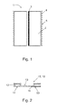
- Fig. 1 shows a schematic sectional view of a Schalldämmelements 1 according to the invention, comprising sound absorber 2, sound reflector 3 and fabric 4.
- the fabric consisting of a textile material 4 contributes to the acoustic effect.
- the fabric 4 designed as an acoustically effective textile, is stretched over a flat side 8 of the Schalldämmelements 1.
- Fig. 1 shows an embodiment in which only one of the two sound absorbers 2 provided with a lamination and this is effective as a sound reflector 3.
- the second sound absorber 2 is arranged directly on the side facing away from the foam flat side of the sound reflector 3.
- the sound reflector 3 comes approximately centrally in the profile of the Schalldämmelements 1 to the arrangement and is effective on both sides as a sound reflector 3, namely for sound waves from the two flat sides 8 impinge on the soundproofing element 1. Therefore, the second sound absorber 2 does not require its own lamination as a sound reflector 3.
- Such an arrangement is very inexpensive, simple and lightweight. It also takes up little space, since a profile of small width is sufficient to absorb much of the spectrum of frequencies in question.
- the two sound absorbers 2 have different strengths.
- a layer structure is achieved with even lower strength. This is sufficient, for example, in cases in which the main sound load is to be expected from one direction, for example from the middle of the room.
- Such sound insulation elements 1 with unbalanced cross-section for example, in the vicinity of ceilings or walls attachable because the sound waves reaching from the room the sound insulation element 1 have a higher intensity than those that are radiated back from the wall or ceiling and the sound insulation element 1 only from the Reach the back. This back can be equipped in this case with a sound absorber 2 lesser strength.
- spacings are drawn between the sound-absorbing elements with one another and with respect to the covering. In fact, however, all the above elements are directly adjacent to each other.
- Fig. 2 shows a schematic sectional view of a frame profile 11 as a part of the frame members 15, 16, the edge region is provided with preferably completely circumferential grooves 12.
- the outer wall 14 to the outside, while the inner wall 13 is aligned with the inner region having the sound-absorbing elements.
- the grooves 12 serve the stability of the frame profile 11, but above all they are suitable to receive a piping arrangement 9 for fixing the fabric 4 over the sound absorber 2, as in the 3 and 4 shown.
- the width of the edges 53 of the frame profile 11 is between 1 and 10 cm, preferably between 3 and 6 cm, and is mainly determined by the sound-absorbing effect as a function of the properties of the Schalldämmelements.
- the width also has an influence on the stability of a combination of frame elements 15, 16, since with narrower frame profiles a greater force acts on the connecting coupling elements under load.
- edges 53 on different frame elements 15, 16 are provided, which can also be combined with one another, so that after the assembly of a plurality of frame elements 15, 16 to a surface higher or lower ranges and corresponding optical effects result.
- the edge 53 is the same on each frame side.
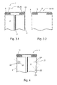
- Fig. 3.1 and 3.2 show schematic sectional views of a Schalldämmelements invention 1 and a frame member 15, 16 including the frame profile 11 and covering 4. It is for clearer representation of a "slice" cut out of the sound insulation, so that the back, the frame inside, is not visible. This applies equally to the FIGS. 4 . 7 and 8th ,
- the sound-absorbing element 1 as shown in FIG Fig. 3.1 has a sound-absorbing structure according to the embodiment according to Fig. 1.1 with two sound absorbers 2 on, one of which is equipped with a sound reflector 3.
- the fabric 4 is connected to a piping to a piping 9, preferably sewn, alternatively glued or welded or joined together in other ways.
- the piping 9 is inserted into the groove 12, wherein the dimensions of the fabric 4 are selected so that they are so strong that they rest directly on the sound absorber 2.
- the frame member 15, 16 receives its outer protective and functional cover.
- Fig. 3.2 shows with respect to the frame profile 11 and the fabric 4 with the piping 9 a corresponding structure.
- the interior of the frame element 15, 16 is different, since no sound absorbers or sound reflectors are present.
- Such a frame element 15, 16 shows a significantly lower sound-absorbing effect, which is caused only by the acoustically effective textile.
- such a frame element 15, 16 cause special optical effects.
- a frame element 15, 16 in the embodiment described above can contribute to the overall impression of a room subsystem.
- the daylight can penetrate through or inside the illumination devices that are installed in the interior come into effect accordingly by illuminating the surrounding area or by causing visual effects on the spatial subsystem.
- Fig. 4 shows schematic sectional views of a Schalldämmelements 1 according to the invention including frame profile 11, covering 4 and lighting means 21, 22, 23, are caused by the optical effects.
- the illustrated, preferably applied installation options of bulbs in the foam need not necessarily be realized on a sound-insulating element 1.
- the overall presentation is for convenience only, so as not to have to submit a separate drawing for each variant.
- the sound absorber 2 For receiving the light sources 21, 22, 23 recesses 24 in the sound absorber 2 are to be introduced. This is particularly easy when using a flexible, thin LED strip 21, 22 is used.
- the sound absorber which is preferably made of a foam, only slotted and the LED strip 21, 22 are inserted into the slot.
- the LED strip 21 radiates outward, so that depending on the optical properties of the fabric 4, a more or less clear luminous spot or a luminous line is formed, which can also be used for illumination purposes.
- the LED strip 22 is designed so that the radiation of the generated light is perpendicular to the band.
- an LED strip 23 is proposed, which is formed in a wider recess, as a groove, introduced in such a way that a preferably made of metal strip is supported on both sides in the walls of the groove thus created and because of the distance to Sound absorber 2 and the cooling properties of the largely exposed LED strip 23 bulbs with higher power can be used.
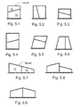
- Fig. 5.1 to 5.19 schematically show a selection of arrangements of frame members 15, 16 to Jardinteilsystemen 48 and Tischteilsystemen 49.
- the shapes formed by a composition of the frame members 15, 16 not only differ from the usual rectangular shape, but also allow the design of very different contours beyond. Nevertheless, such a composition is possible, the rectangles or only slightly different from the rectangle Can produce contours. This makes it very easy to produce a wide variety of combinations and shapes for a wide variety of applications, as well as for specific preferences.
- the corresponding room subsystem 48 or table subsystem 49 can be quickly modified and adapted to changing needs or preferences without the need for tools.
- Coupling devices allow the flexible assembly to a variety of forms of a space subsystem 48 or table subsystem 49, wherein in one embodiment of the invention frame members are covered with different widths of the frame profile, resulting in a composite of frame members 15, 16 area higher or lower areas. Accordingly, the spatial subsystem 48 or the table subsystem 49 results in novel optical effects. The same applies if the composition of frame members 15, 16 to be mounted on a ceiling or a wall.
- Fig. 6 shows a selection of connectivity of plate-shaped elements by coupling means 31, 32, 33 according to the invention.
- the frame sides 29, which in the present embodiment, the first long side 18, the second long side and the narrow sides 19, 20 of the frame members 15, 16 with coupling means 31st , 32, 33 form, hereby equipped.
- Short frame sides 29 have a coupling device 31, 32, 33, longer frame sides 29 a plurality, preferably two coupling devices 31, 32, 33.
- setting-up devices not shown here for installation on the floor or on the table or suspension devices can be attached to the ceiling via the same connection options.
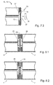
- Fig. 7.1, 7.2 and 7.3 show schematic sectional views of embodiments of coupling devices 31, 32, 33 according to the invention, which provide a very fast and simple, beyond also durable possibility of connection using magnetic forces.
- Fig. 7.1 shows a sound-absorbing element 1 with a magnet 35 which is attached to the inner wall 13 of a frame profile 11, preferably glued. Its magnetic force works through the wall of the frame profile 11 and can be used on the outer wall 14, so that a coupling device 31 results.
- This solution allows a smooth, uninterrupted outer wall 14, in which the coupling device 31 remains invisible.
- Fig. 7.2 shows a frame member 15, 16, in which the frame profile 11 is, however, broken through, preferably through an opening 36. Its shape corresponds to that of the magnet 35. Preferably, it is a round opening 36.
- the magnet 35 can be used and he is already held by its own magnetic force.
- a ferromagnetic plate 37 which is thus attractable by magnetic force, is provided, which is attached to the inner wall 13 of the frame profile 11.
- This coupling device 32 makes it possible to remove the magnet 35 and to change its polarity as needed, in which case it is inserted again into the opening 36.
- Fig. 7.3 essentially combines the advantages of the variants of the coupling devices 31 and 32 described above.
- a ferromagnetic plate 37 is likewise provided on the inner wall 13 of the frame profile 11, during which the outer wall 14 is unworked or, as shown in the exemplary embodiment, provided with a small recess, the exact, positive positioning of the magnet 35 against the not visible from the outside ferromagnetic plate 37, but above all against the intended location of a cooperating coupling device 31, 32, 33 allows.
- Fig. 8.1 and 8.2 shows a selection of possible uses of the coupling devices 31, 32, 33 according to the invention and how they can cooperate and be coupled in use. So is according to Fig. 8.1 always at a coupling device 31 a second magnet 35 is required because otherwise it would not come to attraction forces. As shown, it must then be ensured that always a negative pole and a positive pole come together to form a connection.
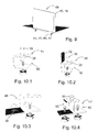
- Fig. 9 shows a table subsystem 49, attached to a table top with Aufstellinraumen 44, 45, 46, 47, whereby, for example, jobs using the frame member 15, 16 can be delimited against each other and at the same time a sound-insulating effect is caused.
- executed by the workplace calls in the area are perceived as less disturbing and the noise level in the room as a whole reduced.
- Fig. 10.1 to 10.4 showers 44, 45, 46, 47 for a table subsystem 49 which have in common that they for connection to a frame member 15, 16 coupling means 31, 32, 33 with the recess 38 on the Aufstellinraumen 44, 45, 46, 47 and at the frame member 15, 16 for the magnet 35 have.
- the holder by means of magnetic force allows easy and quick assembly of the frame members 15, 16.
- the setting-up devices 44, 45, 46, 47 at least one clamp 50 for connection to the table top.
- FIG. 10.1 shows the simple erector 44, which is attached by means of a clamp 50, which may be designed in the illustrated or a similar manner known in the prior art, to a table edge.
- Figure 10.2 shows the positioning device 45, which additionally has a tilt protection 52, so that the frame element does not detach itself from the magnet 35 even with stronger lateral load.
- FIG. 10.3 shows with the raising device 45 a variant that allows the frame member 15, 16 lower below the plane of the table top, so that no horizontal gap between the table top and frame member 15, 16 is formed.
- FIG.4 the positioning device 47, with which two tabletops can be connected, is shown by connecting a respective clamp 50 to one of the tabletops. Above the gap between the two tabletops, likewise secured with a coupling device with magnets 35, a frame element is held by means of magnetic force.
- Fig. 11 shows a space subsystem with hangers 42 for attachment to a ceiling of a room and Aufstellin therapiesen 43 for installation on a floor. Since the space subsystem 48 has a plurality of rows of frame elements 15, 16 one above the other, it is not only placed on the floor by means of positioning devices 43, but additionally has suspension devices 42.
- the positioning devices 43 are designed in the illustrated embodiment as massive slices, for example, have a diameter of 20 cm and a thickness of 3 cm, and stabilize the space subsystem 48 in the state by a high weight.
- the connection between the lower frame member 15, 16 and the Aufstellinoplastyen 43 takes place, as well as the connection between the frame element 15, 16, by means of coupling means 31, 32, 33rd
- connecting strips 51 are provided in the edge regions, in particular laterally and at the lower edge.
- Long connecting strips 51 are provided on the narrow sides of the room subsystem 48, which extend over the entire height of the room subsystem 48.
- the use of short connecting strips 51 is provided which cover only the joints of two frame members 15, 16 and thus avoid unwanted opening of these joints.
- the connection between the connecting strips 51 and the frame members 15, 16 is effected by coupling means 31, 32, 33rd
- connecting strips 51 and setting devices 43 are shown separately and rotated by 90 ° next to the room subsystem 48 by means of a dotted line.
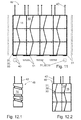
- Fig. 12.1 and 12.2 show variants on a ceiling of a room suspended room subsystems 48.
- the in Fig. 12.1 illustrated variant the peculiarity that the frame members 15, 16 not directly with each other are connected, but are spaced from each other.
- the spacing is preferably achieved by providing cable sections with magnets at their ends, in particular magnets 35, as used in the coupling devices 31, 32, 33.
- Other possibilities of spacing are provided, for example, on hangers 42, which are passed through through openings in the frame members 15, 16 and secured therein.
- FIG. 12.2 a space subsystem 48 is similar to that shown in FIG Fig. 11 is shown. In contrast, however, that no Aufstellin therapiesen for the ground are provided, but only a suspension device 42nd
- a suspension in the middle of the room in order to fulfill the function as a room subsystem 48, also a suspension in the same way directly on or near a wall has been considered in the context of the invention.
- acoustically adverse effects of smooth walls are reduced or caused decorative effects.
- Hanging is done in a very simple manner by the corresponding sound insulation elements similar to a picture and can be hung with corresponding known suspension devices.
Landscapes
- Engineering & Computer Science (AREA)
- Architecture (AREA)
- Physics & Mathematics (AREA)
- Electromagnetism (AREA)
- Civil Engineering (AREA)
- Structural Engineering (AREA)
- Building Environments (AREA)
Applications Claiming Priority (1)
| Application Number | Priority Date | Filing Date | Title |
|---|---|---|---|
| DE102014112556.8A DE102014112556A1 (de) | 2014-09-01 | 2014-09-01 | Akustisch wirksames Raumteilsystem |
Publications (2)
| Publication Number | Publication Date |
|---|---|
| EP2990559A2 true EP2990559A2 (fr) | 2016-03-02 |
| EP2990559A3 EP2990559A3 (fr) | 2016-06-22 |
Family
ID=54014614
Family Applications (1)
| Application Number | Title | Priority Date | Filing Date |
|---|---|---|---|
| EP15183084.1A Withdrawn EP2990559A3 (fr) | 2014-09-01 | 2015-08-31 | Systeme de diviseur d'espace efficace acoustiquement |
Country Status (2)
| Country | Link |
|---|---|
| EP (1) | EP2990559A3 (fr) |
| DE (1) | DE102014112556A1 (fr) |
Cited By (15)
| Publication number | Priority date | Publication date | Assignee | Title |
|---|---|---|---|---|
| EP3404322A1 (fr) * | 2017-05-19 | 2018-11-21 | 3Form, LLC | Déflecteur de feutre à extrémités à encliquetage |
| CN110761399A (zh) * | 2019-10-09 | 2020-02-07 | 中民筑友科技产业有限公司 | 预制墙板的竖向拼接结构及其装配方法 |
| USD915631S1 (en) | 2014-11-14 | 2021-04-06 | 3Form, Llc | Baffle with closed ends |
| USD915634S1 (en) | 2015-05-28 | 2021-04-06 | 3Form, Llc | Tall baffle |
| USD915632S1 (en) | 2013-11-15 | 2021-04-06 | 3Form, Llc | Baffle with reduced height |
| USD915633S1 (en) | 2013-11-15 | 2021-04-06 | 3Form, Llc | Baffle |
| USD917079S1 (en) | 2013-11-15 | 2021-04-20 | 3Form, Llc | Thin baffle |
| USD959030S1 (en) | 2013-11-15 | 2022-07-26 | 3Form, Llc | Baffle with slit end |
| US11530535B2 (en) * | 2019-09-19 | 2022-12-20 | Kadeya Enterprise Co., Ltd | Dividing screen structure |
| WO2022269105A1 (fr) * | 2021-06-22 | 2022-12-29 | Spazia Glass S.L. | Cloisonnette mobile |
| WO2024008832A1 (fr) | 2022-07-05 | 2024-01-11 | Rockwool A/S | Déflecteur acoustique |
| USD1054617S1 (en) | 2022-08-22 | 2024-12-17 | 3Form, Llc | T-shaped light fixture |
| USD1062003S1 (en) | 2022-08-22 | 2025-02-11 | 3Form, Llc | Hexagonal-shaped light fixture |
| USD1062002S1 (en) | 2022-08-22 | 2025-02-11 | 3Form, Llc | X-shaped light fixture |
| USD1062004S1 (en) | 2022-08-22 | 2025-02-11 | 3Form, Llc | Y-shaped light fixture |
Families Citing this family (5)
| Publication number | Priority date | Publication date | Assignee | Title |
|---|---|---|---|---|
| DE102016120095A1 (de) * | 2016-10-21 | 2018-04-26 | König + Neurath AG | Trennwand |
| DE102019206557A1 (de) * | 2019-05-07 | 2020-11-12 | Rentex Wand- Und Deckensysteme Gmbh | Wand-/Deckensystem |
| DE102019121941B4 (de) | 2019-08-14 | 2022-01-13 | Deutsche Institute Für Textil- Und Faserforschung Denkendorf | Schallabsorber |
| DE202023107179U1 (de) | 2023-12-04 | 2025-03-07 | Michael Eisele | Schallabsorptionselement |
| DE102024105186A1 (de) * | 2024-02-23 | 2025-08-28 | Manfred Köstlmeier | Schallschutzvorrichtung |
Citations (16)
| Publication number | Priority date | Publication date | Assignee | Title |
|---|---|---|---|---|
| DE1534746A1 (de) | 1965-09-20 | 1969-09-04 | Const Roch Sarl Macornay | Vorrichtung zum Verbinden von Bauelementen |
| DE7206572U (de) | 1972-05-18 | Metallwarenfab Menke Kunalwerk Kg | Einhängebeschlag zum lösbaren Zusammenbau von Möbelteilen, vorzugsweise von Shopsäulen und -wänden | |
| US4112643A (en) | 1977-05-09 | 1978-09-12 | Harter Corporation | Snub assembly for securing covering material to a wall panel module |
| US4213516A (en) | 1978-11-29 | 1980-07-22 | American Seating Company | Acoustical wall panel |
| EP0133269A2 (fr) | 1983-07-29 | 1985-02-20 | The Tandem Group Inc. | Dispositif de verrouillage pour un système de cloison de bureau |
| WO1999058780A1 (fr) | 1998-05-08 | 1999-11-18 | Tetrad Marketing/Sales Ltd. | Structure en panneaux et systeme de fixation |
| DE19844027A1 (de) | 1998-09-25 | 2000-03-30 | Preform Raumgliederungssysteme | Verbindungselement zur Verbindung zweier Komponenten einer Trennwand sowie Verwendung eines derartigen Verbindungselements |
| DE19844028A1 (de) | 1998-09-25 | 2000-03-30 | Preform Raumgliederungssysteme | Trennwand |
| DE10326196B3 (de) | 2003-06-07 | 2004-11-25 | Frank Prochiner | Hochlastverbindungselement für Wände |
| DE202006018839U1 (de) | 2006-12-04 | 2007-02-22 | Octanorm-Vertriebs-GmbH für Bauelemente | System zum Erstellen von Aufbauten und Tragprofil |
| DE202007002913U1 (de) | 2007-02-26 | 2008-07-10 | Rehau Ag + Co | Wandelement |
| DE202009016304U1 (de) | 2009-12-01 | 2010-04-15 | Vidoni, Werner | Federndes Verbindungselement für Platten |
| DE202010010269U1 (de) | 2010-07-05 | 2010-10-14 | Strähle, Paul | Absorberelement mit textiler Oberfläche |
| DE102010034051A1 (de) | 2010-08-11 | 2012-02-16 | Röder HTS Höcker GmbH | System zur variablen Gestaltung einer Fensterfassade und ein Verfahren zur Herstellung einer Fensterfassade |
| DE202012001857U1 (de) | 2012-02-22 | 2012-05-03 | Karsten Fey | Schallabsorber |
| DE102012017901A1 (de) | 2012-09-11 | 2014-05-28 | Acousticpearls Gmbh | Textiles Akustik- Paneel in Sandwichbauweise |
Family Cites Families (7)
| Publication number | Priority date | Publication date | Assignee | Title |
|---|---|---|---|---|
| FR1492920A (fr) * | 1966-05-10 | 1967-08-25 | Fermes en éléments emboutis | |
| US3949827A (en) * | 1975-04-24 | 1976-04-13 | Owens-Corning Fiberglas Corporation | Acoustical panel assembly |
| US4214646A (en) * | 1978-06-19 | 1980-07-29 | Conwed Corporation | Space divider and acoustic panel |
| US4624083A (en) * | 1983-12-05 | 1986-11-25 | Hauserman, Inc. | Screen system for offices and method of making and installing same |
| SE9002942D0 (sv) * | 1990-09-14 | 1990-09-14 | Ahlberg & Co Ab | I ett stycke av plast format snaepplaasdon |
| GB2507129A (en) * | 2012-10-22 | 2014-04-23 | Viig Ltd | Tessellating panel with magnets to provide secure interface with adjacent panels. |
| CH708188A2 (de) * | 2013-05-29 | 2014-12-15 | Sonami Ag | Schalldämmplatte mit Leuchtmittel. |
-
2014
- 2014-09-01 DE DE102014112556.8A patent/DE102014112556A1/de not_active Ceased
-
2015
- 2015-08-31 EP EP15183084.1A patent/EP2990559A3/fr not_active Withdrawn
Patent Citations (16)
| Publication number | Priority date | Publication date | Assignee | Title |
|---|---|---|---|---|
| DE7206572U (de) | 1972-05-18 | Metallwarenfab Menke Kunalwerk Kg | Einhängebeschlag zum lösbaren Zusammenbau von Möbelteilen, vorzugsweise von Shopsäulen und -wänden | |
| DE1534746A1 (de) | 1965-09-20 | 1969-09-04 | Const Roch Sarl Macornay | Vorrichtung zum Verbinden von Bauelementen |
| US4112643A (en) | 1977-05-09 | 1978-09-12 | Harter Corporation | Snub assembly for securing covering material to a wall panel module |
| US4213516A (en) | 1978-11-29 | 1980-07-22 | American Seating Company | Acoustical wall panel |
| EP0133269A2 (fr) | 1983-07-29 | 1985-02-20 | The Tandem Group Inc. | Dispositif de verrouillage pour un système de cloison de bureau |
| WO1999058780A1 (fr) | 1998-05-08 | 1999-11-18 | Tetrad Marketing/Sales Ltd. | Structure en panneaux et systeme de fixation |
| DE19844027A1 (de) | 1998-09-25 | 2000-03-30 | Preform Raumgliederungssysteme | Verbindungselement zur Verbindung zweier Komponenten einer Trennwand sowie Verwendung eines derartigen Verbindungselements |
| DE19844028A1 (de) | 1998-09-25 | 2000-03-30 | Preform Raumgliederungssysteme | Trennwand |
| DE10326196B3 (de) | 2003-06-07 | 2004-11-25 | Frank Prochiner | Hochlastverbindungselement für Wände |
| DE202006018839U1 (de) | 2006-12-04 | 2007-02-22 | Octanorm-Vertriebs-GmbH für Bauelemente | System zum Erstellen von Aufbauten und Tragprofil |
| DE202007002913U1 (de) | 2007-02-26 | 2008-07-10 | Rehau Ag + Co | Wandelement |
| DE202009016304U1 (de) | 2009-12-01 | 2010-04-15 | Vidoni, Werner | Federndes Verbindungselement für Platten |
| DE202010010269U1 (de) | 2010-07-05 | 2010-10-14 | Strähle, Paul | Absorberelement mit textiler Oberfläche |
| DE102010034051A1 (de) | 2010-08-11 | 2012-02-16 | Röder HTS Höcker GmbH | System zur variablen Gestaltung einer Fensterfassade und ein Verfahren zur Herstellung einer Fensterfassade |
| DE202012001857U1 (de) | 2012-02-22 | 2012-05-03 | Karsten Fey | Schallabsorber |
| DE102012017901A1 (de) | 2012-09-11 | 2014-05-28 | Acousticpearls Gmbh | Textiles Akustik- Paneel in Sandwichbauweise |
Cited By (18)
| Publication number | Priority date | Publication date | Assignee | Title |
|---|---|---|---|---|
| USD915632S1 (en) | 2013-11-15 | 2021-04-06 | 3Form, Llc | Baffle with reduced height |
| USD959030S1 (en) | 2013-11-15 | 2022-07-26 | 3Form, Llc | Baffle with slit end |
| USD917079S1 (en) | 2013-11-15 | 2021-04-20 | 3Form, Llc | Thin baffle |
| USD916348S1 (en) | 2013-11-15 | 2021-04-13 | 3Form, Llc | Light-weight lighting fixture |
| USD915633S1 (en) | 2013-11-15 | 2021-04-06 | 3Form, Llc | Baffle |
| USD915631S1 (en) | 2014-11-14 | 2021-04-06 | 3Form, Llc | Baffle with closed ends |
| USD915634S1 (en) | 2015-05-28 | 2021-04-06 | 3Form, Llc | Tall baffle |
| EP3404322A1 (fr) * | 2017-05-19 | 2018-11-21 | 3Form, LLC | Déflecteur de feutre à extrémités à encliquetage |
| US10889987B2 (en) | 2017-05-19 | 2021-01-12 | 3Form, Llc | Felt baffle with snap ends |
| US10876290B2 (en) | 2017-05-19 | 2020-12-29 | 3Form, Llc | Felt baffle with snap ends |
| US11530535B2 (en) * | 2019-09-19 | 2022-12-20 | Kadeya Enterprise Co., Ltd | Dividing screen structure |
| CN110761399A (zh) * | 2019-10-09 | 2020-02-07 | 中民筑友科技产业有限公司 | 预制墙板的竖向拼接结构及其装配方法 |
| WO2022269105A1 (fr) * | 2021-06-22 | 2022-12-29 | Spazia Glass S.L. | Cloisonnette mobile |
| WO2024008832A1 (fr) | 2022-07-05 | 2024-01-11 | Rockwool A/S | Déflecteur acoustique |
| USD1054617S1 (en) | 2022-08-22 | 2024-12-17 | 3Form, Llc | T-shaped light fixture |
| USD1062003S1 (en) | 2022-08-22 | 2025-02-11 | 3Form, Llc | Hexagonal-shaped light fixture |
| USD1062002S1 (en) | 2022-08-22 | 2025-02-11 | 3Form, Llc | X-shaped light fixture |
| USD1062004S1 (en) | 2022-08-22 | 2025-02-11 | 3Form, Llc | Y-shaped light fixture |
Also Published As
| Publication number | Publication date |
|---|---|
| EP2990559A3 (fr) | 2016-06-22 |
| DE102014112556A1 (de) | 2016-03-03 |
Similar Documents
| Publication | Publication Date | Title |
|---|---|---|
| DE102014112556A1 (de) | Akustisch wirksames Raumteilsystem | |
| AT509687B1 (de) | Trennwand mit integrierter beleuchtung | |
| EP2980329B1 (fr) | Élement de paroi et de plafond, et montage de paroi et de plafond compose d'élements | |
| DE102011015905B4 (de) | Leuchte | |
| AT510641B1 (de) | Schallabsorbierende leuchte | |
| EP3587691B1 (fr) | Dispositif absorbant le bruit | |
| DE202012012556U1 (de) | Textiles Akustik-Paneel in Sandwichbauweise | |
| EP1996410B1 (fr) | Systeme modulaire de decoration de paroi dote d'un cadre et d'une plaque decorative | |
| DE2510794A1 (de) | Gitterfoermiges drahtgebilde mit schallschluck-material | |
| CH719045A2 (de) | Schallabsorbierendes Akustikelement und Schallabsorber. | |
| DE202021103171U1 (de) | Modulare Arbeitsplatzkabine | |
| DE202011050894U1 (de) | Verbauungssystem für eine Infrarotheizung | |
| EP3587688A2 (fr) | Elément de plafond acoustique, support de plafond pour un élément de plafond acoustique ainsi que système de plafond acoustique et écarteur | |
| WO2016037603A1 (fr) | Protection visuelle et système de protections visuelles | |
| DE102012207754A1 (de) | Raumgliederungselement für ein Großraumbüro | |
| DE202012005495U1 (de) | Stellwandsystem zum Unterdrücken von Schallwellen vorbestimmter Frequenzbänder | |
| DE202011004480U1 (de) | Schallabsorber | |
| DE4229712A1 (de) | Vorrichtung zur schalldaemmung in grossraeumen | |
| CH712881B1 (de) | Raum-in-Raum System zur Bildung einer Raumzelle. | |
| DE202014009761U1 (de) | Lamelle und Decken- und/oder Wandverkleidung hiermit | |
| EP4571005A1 (fr) | Plafond | |
| EP2650451B1 (fr) | Module mural flexible | |
| DE9417997U1 (de) | Leuchte | |
| DE202010008538U1 (de) | Halter für liegende Fassadenplatten | |
| DE19901607C2 (de) | Schalldämpfungsmittel |
Legal Events
| Date | Code | Title | Description |
|---|---|---|---|
| PUAI | Public reference made under article 153(3) epc to a published international application that has entered the european phase |
Free format text: ORIGINAL CODE: 0009012 |
|
| AK | Designated contracting states |
Kind code of ref document: A2 Designated state(s): AL AT BE BG CH CY CZ DE DK EE ES FI FR GB GR HR HU IE IS IT LI LT LU LV MC MK MT NL NO PL PT RO RS SE SI SK SM TR |
|
| AX | Request for extension of the european patent |
Extension state: BA ME |
|
| PUAL | Search report despatched |
Free format text: ORIGINAL CODE: 0009013 |
|
| RIC1 | Information provided on ipc code assigned before grant |
Ipc: F21V 33/00 20060101ALI20160512BHEP Ipc: E04B 2/74 20060101AFI20160512BHEP Ipc: E04B 1/61 20060101ALI20160512BHEP Ipc: A47B 1/00 20060101ALI20160512BHEP |
|
| AK | Designated contracting states |
Kind code of ref document: A3 Designated state(s): AL AT BE BG CH CY CZ DE DK EE ES FI FR GB GR HR HU IE IS IT LI LT LU LV MC MK MT NL NO PL PT RO RS SE SI SK SM TR |
|
| AX | Request for extension of the european patent |
Extension state: BA ME |
|
| RIC1 | Information provided on ipc code assigned before grant |
Ipc: E04B 2/74 20060101AFI20160513BHEP Ipc: F21V 33/00 20060101ALI20160513BHEP Ipc: E04B 1/61 20060101ALI20160513BHEP Ipc: A47B 1/00 20060101ALI20160513BHEP |
|
| STAA | Information on the status of an ep patent application or granted ep patent |
Free format text: STATUS: REQUEST FOR EXAMINATION WAS MADE |
|
| 17P | Request for examination filed |
Effective date: 20161214 |
|
| RBV | Designated contracting states (corrected) |
Designated state(s): AL AT BE BG CH CY CZ DE DK EE ES FI FR GB GR HR HU IE IS IT LI LT LU LV MC MK MT NL NO PL PT RO RS SE SI SK SM TR |
|
| STAA | Information on the status of an ep patent application or granted ep patent |
Free format text: STATUS: EXAMINATION IS IN PROGRESS |
|
| 17Q | First examination report despatched |
Effective date: 20170718 |
|
| GRAP | Despatch of communication of intention to grant a patent |
Free format text: ORIGINAL CODE: EPIDOSNIGR1 |
|
| STAA | Information on the status of an ep patent application or granted ep patent |
Free format text: STATUS: GRANT OF PATENT IS INTENDED |
|
| RIC1 | Information provided on ipc code assigned before grant |
Ipc: F21V 33/00 20060101ALI20200702BHEP Ipc: F21Y 115/10 20160101ALN20200702BHEP Ipc: E04B 2/74 20060101AFI20200702BHEP Ipc: A47B 1/00 20060101ALI20200702BHEP Ipc: E04B 1/61 20060101ALI20200702BHEP |
|
| INTG | Intention to grant announced |
Effective date: 20200724 |
|
| STAA | Information on the status of an ep patent application or granted ep patent |
Free format text: STATUS: THE APPLICATION IS DEEMED TO BE WITHDRAWN |
|
| 18D | Application deemed to be withdrawn |
Effective date: 20201204 |