EP2990667A1 - Passe-câble isolant à vis en plastique et procédés associés - Google Patents
Passe-câble isolant à vis en plastique et procédés associés Download PDFInfo
- Publication number
- EP2990667A1 EP2990667A1 EP15182340.8A EP15182340A EP2990667A1 EP 2990667 A1 EP2990667 A1 EP 2990667A1 EP 15182340 A EP15182340 A EP 15182340A EP 2990667 A1 EP2990667 A1 EP 2990667A1
- Authority
- EP
- European Patent Office
- Prior art keywords
- screw
- grommet
- plastic
- serviceable
- screw grommet
- Prior art date
- Legal status (The legal status is an assumption and is not a legal conclusion. Google has not performed a legal analysis and makes no representation as to the accuracy of the status listed.)
- Granted
Links
Images


Classifications
-
- F—MECHANICAL ENGINEERING; LIGHTING; HEATING; WEAPONS; BLASTING
- F16—ENGINEERING ELEMENTS AND UNITS; GENERAL MEASURES FOR PRODUCING AND MAINTAINING EFFECTIVE FUNCTIONING OF MACHINES OR INSTALLATIONS; THERMAL INSULATION IN GENERAL
- F16B—DEVICES FOR FASTENING OR SECURING CONSTRUCTIONAL ELEMENTS OR MACHINE PARTS TOGETHER, e.g. NAILS, BOLTS, CIRCLIPS, CLAMPS, CLIPS OR WEDGES; JOINTS OR JOINTING
- F16B13/00—Dowels or other devices fastened in walls or the like by inserting them in holes made therein for that purpose
- F16B13/04—Dowels or other devices fastened in walls or the like by inserting them in holes made therein for that purpose with parts gripping in the hole or behind the reverse side of the wall after inserting from the front
- F16B13/06—Dowels or other devices fastened in walls or the like by inserting them in holes made therein for that purpose with parts gripping in the hole or behind the reverse side of the wall after inserting from the front combined with expanding sleeve
- F16B13/063—Dowels or other devices fastened in walls or the like by inserting them in holes made therein for that purpose with parts gripping in the hole or behind the reverse side of the wall after inserting from the front combined with expanding sleeve by the use of an expander
-
- F—MECHANICAL ENGINEERING; LIGHTING; HEATING; WEAPONS; BLASTING
- F16—ENGINEERING ELEMENTS AND UNITS; GENERAL MEASURES FOR PRODUCING AND MAINTAINING EFFECTIVE FUNCTIONING OF MACHINES OR INSTALLATIONS; THERMAL INSULATION IN GENERAL
- F16B—DEVICES FOR FASTENING OR SECURING CONSTRUCTIONAL ELEMENTS OR MACHINE PARTS TOGETHER, e.g. NAILS, BOLTS, CIRCLIPS, CLAMPS, CLIPS OR WEDGES; JOINTS OR JOINTING
- F16B37/00—Nuts or like thread-engaging members
- F16B37/04—Devices for fastening nuts to surfaces, e.g. sheets, plates
- F16B37/041—Releasable devices
- F16B37/043—Releasable devices with snap action
Definitions
- the present disclosure relates to a plastic screw grommet for connecting and securing a component to a joining part, such as an automotive panel and, more specifically, to such plastic screw grommets having laterally extending retention wings in addition to laterally expanding legs.
- Pin and grommet fasteners are commonly used in the automotive industry. Use of a pin and grommet fastener typically requires insertion of the grommet into an aperture of a joining part.
- Such grommets can include retention wings extending from opposite sides of the grommet. Such retention wings are typically angled downwardly away from horizontal hinged ends to provide engaging surfaces or stops at the opposite end of the wing.
- the wings flex inwardly along the hinge until they are released by the aperture when they flex outwardly, causing the stops to engage against the periphery of the aperture. In this way, the grommet can be appropriately positioned and held against the joining part until the legs of the grommet are laterally expanded by inserting the screw into the grommet.
- Serviceability can be a problem for such screw grommets because the retention wings can make it difficult, if not impossible, to remove the grommet once it has been inserted without causing damage to the parts. Even after the screw has been removed from the grommet allowing the legs to return to their unexpanded state or position, the stops of the wings remain locked against the joining part. Thus, attempts to remove the grommet for servicing can damage the grommet, the joining part, or both. Damage to the grommet can be particularly problematic where the grommet is integrally molded as a single piece component that is being joined to the joining part. Thus, servicing can require replacement of the joining part, the grommet bearing part, or both.
- a plastic serviceable screw grommet for joining automobile components can include a base and a pair of legs extending upwardly from the base and defining screw passage between the legs.
- the screw passage can define a central longitudinal axis.
- a retaining wing can be hingedly coupled to an outer surface of each of the legs along a hinge line. Each retaining wing can extend outwardly from the outer surface.
- the hinge line can extend parallel to the central longitudinal axis or at a hinge line angle that is less than about 45 degrees from the central longitudinal axis.
- the retaining wing can have a trailing edge defining a retention surface.
- the retention surface When the screw grommet is inserted into an aperture of a first of the automobile components, at least a portion of the retention surface can extend along its length at a retention angle relative to an adjacent surface of the first of the automobile components.
- the retention angle can be such that engagement of the retention surface against the first of the automobile components can operate to direct a portion of a servicing removal force applied to the screw grommet inwardly on the wings causing the wings to flex inwardly to a collapsed position and permit removal of the screw grommet from the aperture without damaging any of the grommet and the automobile components and without the need to apply a separate inwardly directed force against the wings.
- a plastic serviceable screw grommet for joining automobile components can include a base and a pair of legs extending upwardly from the base and defining screw passage between the legs.
- the screw passage can define a central longitudinal axis.
- a retaining wing can be hingedly coupled to an outer surface of each of the legs along a hinge line.
- the retaining wing can extend outwardly from the outer surface.
- the retaining wing can include a leading edge facing toward a distal end of the legs and a trailing edge facing away from the distal end of the legs.
- the hinge line, leading edge, and trailing edge can define a substantially triangular shape.
- engagement of the trailing edge against the first of the automobile components can operate to direct a portion of a servicing removal force, applied to the screw grommet through the base, inwardly on the wings causing the wings to flex inwardly to a collapsed position that permits removal of the screw grommet from the aperture without damaging any of the grommet and the automobile components and without requiring any separate inwardly directed force to be directly applied to the wings.
- a method of removing a plastic serviceable screw grommet from an aperture of a first automobile component after the grommet has been inserted in to the aperture is also provided.
- the method can include removing a screw from a screw passage defined between a pair of legs extending from a base of the plastic serviceable screw grommet.
- a servicing removal force can be applied to the screw grommet, causing the first automobile component to engage a trailing edge, facing away from the distal end of the legs, of a substantially triangularly shaped retaining wing that is hingedly coupled to, and extending outwardly from, an outer surface of each of the legs along a hinge line.
- the engagement of the trailing edge against the first automobile component can operate to direct a portion of a servicing removal force, applied to the screw grommet through the base, inwardly on the wings causing the wings to flex inwardly to a collapsed position and permit removal of the screw grommet from the aperture without damaging any of the grommet and the automobile components.
- Continuing to remove the grommet from the aperture over the retaining wings can engage the first automobile component along a leading edge facing toward the distal end of the legs, which leading edge, hinge line, and trailing edge can define the substantially triangular shape.
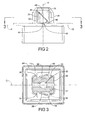
- a screw grommet 20 can generally include a base 22, a pair of legs 24, and a retaining wing 26 hingedly extending from each of the legs 24.
- the base 22 can include an engaging surface 28 against which a joining part 30 rests, and the engaging surface 28 can define a joining plane "P" (corresponding to the lower surface of the joining part 30 in Fig. 2 ).
- the legs 24 extend from the base 22 with the base 22 and legs 24 defining a screw passage 32 between the legs 24.
- the screw passage 32 can have a longitudinal axis "A.”
- the longitudinal axis "A" can be substantially perpendicular to the joining plane "P.”
- the base 22, and therefore the entirety of the plastic screw grommet 20, can be integrally molded as a single part of a plastic component that is to be joined to the joining part 30.
- the plastic component can have a plurality of plastic screw grommets 20 integrally molded therewith; each screw grommet 20 being provided for insertion into a corresponding aperture 31 of the joining part 30.
- the base 22 can also include a recessed surface 29 below the engaging surface 28. This can enable a foam or resilient member 50, which can have a shape generally corresponding to the shape of the recessed surface 29, to be provided between the recessed surface 29 of the screw grommet 20 and the adjacent surface of the joining part 30.
- the wings 26 can retain the foam member 50 on the screw grommet 20 during shipping from the grommet manufacturer to the user.
- Each leg 24 can include a central laterally recessed area 34.
- each leg 24 includes a laterally inwardly recessed area 34 defined between end portions 36 that protrude laterally outwardly relative to the recessed area 34.
- the retaining wing 26 of each leg 24 can be hingedly coupled to the leg 24 in the recessed area 34. This can permit the wings 26 to have a size and shape that is more substantial than could be provided without the recessed area 34. Thus, the necessary retention force can be provided while also enabling removal of the grommet 20 for servicing as described hereinafter.
- two wings 26 are shown in the illustrated example, more or less wings 26 can be provided. In other words, at least one or at least two wings 26 can be desirable in some instances.
- each wing need not have the same configuration. In other words, the thickness, angles, etc. can be different for different wings.
- the retaining wings 26 can have a generally triangular shape, which can further resemble a right triangle.
- the generally triangular shape of the retaining wing can be truncated at its uppermost end (as oriented in Fig 2 ) adding another small upwardly facing side as indicated by dotted line 48 in Fig. 2 .
- Each retaining wing 26 can be hingedly coupled to its corresponding leg 24 along a hinge line or edge 38.
- the hinge line 38 can extend in a direction that is substantially parallel to the longitudinal axis "A" of the screw passage 32, or substantially perpendicular to the joining plane "P," or both. In some cases, the hinge line 38 can extend in a direction that is less than about 45 degrees from the longitudinal axis "A”. Similarly, the hinge line 38 can extend in a direction that is more than about 45 degrees from the joining plane "P.”
- the wings 26, including at the hinged coupling can have a thickness of greater than or equal to 0.5 mm.
- the wing 26 can extend at an angle relative to the wall of the recessed area 34 or relative to the central plane "C" that, in some cases, can be between about 2 degrees and about 46 degrees, in some cases, this angle can be between about 5 degrees and about 35 degrees, in some cases, this angle can be between about 10 degrees and about 20 degrees and in some cases, this angle can be about 16 degrees.
- the overall width "W" of the wing 26 can be between about 2 mm and about 10 mm, in some cases, this overall width "W” can be between about 2 mm and about 8 mm, in some cases, this overall width "W” can be between about 3 mm and about 7 mm, and in some cases is about 5 mm.
- Each wing 26 has a leading edge 40 and a trailing edge 42 during insertion.
- the leading edge 40 can extend at an angle relative to the longitudinal axis "A" or relative to the hinge line 38 that, in some cases, can be between about 14 degrees and about 74 degrees, in some cases, this angle can be between about 30 degrees and about 60 degrees, in some cases, this angle can be between about 40 degrees and about 50 degrees and in some cases, this angle can be about 44 degrees.
- the leading edge 40 of the wing 26 can have a beveled or chamfered outer edge along its length.
- the chamfer or bevel can, in some cases, be between about 5 degrees and about 70 degrees, in some cases, this angle can be between about 15 degrees and about 55 degrees, in some cases, this angle can be between about 25 degrees and about 45 degrees and in some cases, this angle can be about 35 degrees.
- the trailing edge 42 can define a compound retention surface 44 and 46.
- Proximal portion 44 of the trailing edge 42 or retention surface 42 can extend at an angle relative to the joining plane "P" or to the adjacent surface of the joining part 30 that, in some cases, can be between about zero degrees and about 15 degrees; in some cases, this angle can be between about 3 degrees and about 10 degrees, and in some cases, this angle can be about 5 degrees.
- the compound retention surface 44 and 46, such as the proximal portion 44 can comprise such angles as described.
- Distal portion 46 of the retention surface 42 can extend at an angle relative to the joining plane "P" or to the adjacent surface of the joining part 30 that, in some cases, can be between about 12 degrees and about 33 degrees; in some cases, this angle can be between about 17 degrees and about 28 degrees, and in some cases, this angle can be about 23 degrees.
- the compound retention surface 44 and 46, such as the distal portion can comprise such angles as described.
- the distal end of distal portion 46 can be radiused as illustrated in the drawings.
- the "servicing removal force” means the separating force required to remove the grommet 20 from the joining part 30 (after removing the screw 52) without damaging the grommet 20 or the joining part 30.
- the servicing removal force is applied as a separating force (generally along line A) between the grommet 20 and joining part 30. Due to the configuration of the wings 26, this separating servicing removal force is partially converted to a laterally inwardly directed force acting on the wings 26 to move them toward their collapsed position as discussed herein.
- the grommet 20 can be removed from the aperture 31 of the joining part 30 without damaging the grommet 20 or joining part 30 and without the need to separately apply a laterally inwardly directed force against the wings 26, which are often inaccessible when the grommet 20 is assembled to the joining part 30.
- Associated methods of manufacturing and using the serviceable screw grommet 20 should be apparent from the above discussion.
- such methods of manufacturing the serviceable screw grommet 20 can include providing a plastic serviceable screw grommet 20 with any combination of the features, sizes, angles, etc., described herein.
- a foam or resilient member 50 can be assembled around the legs 24 of the plastic serviceable screw grommet 20 and retained by the wings 26 during shipment to the user.
- the user can insert the plastic serviceable screw grommet 20 into a corresponding aperture 31 of the joining part 30.
- Edges of the aperture 31 of the joining part 30 can engage along the leading edge 40 of the wings 26 causing them to move laterally inwardly (opposite to the direction indicated by arrows "O" of Fig. 5 ) toward a flexed or collapsed position adjacent the wall of the corresponding recess 34.
- the upper surface (as oriented in Fig. 2 ) of the joining part 30 moves past the trailing edge 42 of the wings 26, the wings 26 return to their laterally outwardly extended position. In this laterally outwardly extended position, the trailing edge 42 of the wings 26 can engage against the upper surface (as oriented in Fig.
- the screw grommet 20 is releasably coupled to the joining part 30, because it can be removed without damage as discussed herein.
- the screw 52 can then be inserted into the screw passage 32 causing the legs 24 to extend laterally outwardly (as indicated by arrows "O" in Fig. 5 ).
- the plastic serviceable screw grommet 20 cannot be removed from the joining panel 30 without damaging the joining panel 30, the screw grommet 20, or both.
- the grommet 20 is non-releasably or fully coupled to the joining part or panel 30.
- this can be done for a plurality of screw grommets 20 integrally molded together as a single piece plastic component to be joined to the joining part 30 via a corresponding plurality of cooperating apertures 31.
- the screw 52 can be removed from the screw passage 32, allowing the legs 24 to move laterally inwardly toward their original, unexpanded position.
- the grommet is returned to the state where it is releasably coupled to the joining part 30.
- the legs 24 do not prevent removal of the plastic serviceable screw grommet 20 from the aperture 31 of the joining part 30 without damaging the grommet 20 or the joining part 30.
- the trailing surface of the wings 26 can be provided with a configuration that, upon application of a servicing removal force (substantially along axis "A") to separate the grommet 20 from the joining part 30, causes the wings 26 to flex laterally inwardly toward their collapsed positions allowing the grommet 20 to be removed from the joining part 30 without damaging the grommet 20 or the joining panel 30 and without the need to separately access or exert any other force on the wings 26.
- a servicing removal force substantially along axis "A”
- the trailing edge 42 of the wings 26 of the plastic screw grommet 20 can be angled so that as a pull-out or servicing removal force is applied to the base 22 of the grommet 20 (when the screw 52 is removed) the trailing edge 42 angle(s) operate to direct a portion of the pull-out or servicing removal force inwardly on the wings 26, causing the wings 26 to move inwardly and allowing removal and reuse of the grommet 20.
- this can include the trailing edge 42 comprising any one or combination of the proximal portion 44 and distal portion 46 of the trailing edge 42 with the angles described herein.
- it can also include providing the radiused distal end of distal portion 46 of the wing 26.
Landscapes
- Engineering & Computer Science (AREA)
- General Engineering & Computer Science (AREA)
- Mechanical Engineering (AREA)
- Dowels (AREA)
Applications Claiming Priority (2)
| Application Number | Priority Date | Filing Date | Title |
|---|---|---|---|
| US201462042879P | 2014-08-28 | 2014-08-28 | |
| US14/825,313 US9599140B2 (en) | 2014-08-28 | 2015-08-13 | Plastic serviceable screw grommet and related methods |
Publications (2)
| Publication Number | Publication Date |
|---|---|
| EP2990667A1 true EP2990667A1 (fr) | 2016-03-02 |
| EP2990667B1 EP2990667B1 (fr) | 2017-09-27 |
Family
ID=54065185
Family Applications (1)
| Application Number | Title | Priority Date | Filing Date |
|---|---|---|---|
| EP15182340.8A Active EP2990667B1 (fr) | 2014-08-28 | 2015-08-25 | Passe-câble isolant à vis en plastique et procédés associés |
Country Status (3)
| Country | Link |
|---|---|
| US (1) | US9599140B2 (fr) |
| EP (1) | EP2990667B1 (fr) |
| JP (1) | JP6616627B2 (fr) |
Families Citing this family (6)
| Publication number | Priority date | Publication date | Assignee | Title |
|---|---|---|---|---|
| CN206191809U (zh) * | 2016-09-22 | 2017-05-24 | 广东松下环境系统有限公司 | 换气装置 |
| US10900514B2 (en) | 2017-11-07 | 2021-01-26 | Hellermanntyton Corporation | Wire-tray-assembly with stud-mount inserts |
| USD880993S1 (en) * | 2018-04-05 | 2020-04-14 | Illinois Tool Works Inc. | Mounting device |
| US11253069B2 (en) * | 2019-02-06 | 2022-02-22 | Organized Living, Inc. | Hanging rack assemblies and methods of use |
| US11078943B2 (en) * | 2019-11-26 | 2021-08-03 | GM Global Technology Operations LLC | Fastener assembly |
| US11451025B2 (en) * | 2020-12-22 | 2022-09-20 | Hellermann Tyton Corporation | Wire tray and mounting insert assemblies |
Citations (3)
| Publication number | Priority date | Publication date | Assignee | Title |
|---|---|---|---|---|
| DE1173737B (de) * | 1958-05-05 | 1964-07-09 | Illinois Tool Works | Einstueckige Steckmutter aus elastischem Werk-stoff, insbesondere Kunststoff |
| US5636953A (en) * | 1996-06-11 | 1997-06-10 | Trw Inc. | Roof rail attachment assembly |
| DE19709857A1 (de) * | 1996-03-15 | 1997-11-06 | Mecano Rapid Gmbh | Dichtungselement |
Family Cites Families (35)
| Publication number | Priority date | Publication date | Assignee | Title |
|---|---|---|---|---|
| US2836215A (en) * | 1954-08-11 | 1958-05-27 | Illinois Tool Works | Plastic nut-like fastener with resilient wings |
| US3241428A (en) | 1962-02-21 | 1966-03-22 | Fischer Artur | Plastic fastening device |
| US3342098A (en) * | 1965-08-16 | 1967-09-19 | Tinnerman Products Inc | Sealed expansion fastener |
| US3701373A (en) * | 1971-03-03 | 1972-10-31 | Illinois Tool Works | Grommet type fastener |
| US3701302A (en) * | 1971-03-29 | 1972-10-31 | Illinois Tool Works | Grommet type fastener |
| US3756116A (en) | 1971-09-27 | 1973-09-04 | Fastway Fasteners | Plastic nut or grommet |
| US4077300A (en) | 1973-09-10 | 1978-03-07 | Nifco Inc. | Plastic screw grommet |
| US3871430A (en) | 1973-10-26 | 1975-03-18 | Usm Corp | Retainer clip |
| JPS56970Y2 (fr) | 1975-05-07 | 1981-01-12 | ||
| US4082030A (en) | 1977-03-25 | 1978-04-04 | Illinois Tool Works, Inc. | Plastic screw grommet |
| FR2386721A1 (fr) | 1977-04-05 | 1978-11-03 | Itw De France | Ecrou d'assemblage en matiere plastique permettant des defauts d'alignement d'entraxes entre les elements a assembler |
| JPS5958206U (ja) | 1982-10-12 | 1984-04-16 | 株式会社青山製作所 | 合成樹脂製グロメツト |
| US4657458A (en) | 1983-11-07 | 1987-04-14 | Phillips Plastics Corporation | Anchor nut for threaded member |
| JPS6117709A (ja) | 1984-07-02 | 1986-01-25 | 株式会社ニフコ | スクリユ−グロメツト |
| JPH045766Y2 (fr) | 1984-09-07 | 1992-02-18 | ||
| JPS6217410A (ja) | 1985-07-15 | 1987-01-26 | 株式会社ニフコ | 2枚のパネルを接面状に止着するための留め具 |
| JPH0413446Y2 (fr) | 1987-06-30 | 1992-03-30 | ||
| US4927306A (en) | 1988-05-18 | 1990-05-22 | Kato Hatsujo Kaisha, Ltd. | Screw grommet |
| US5028190A (en) * | 1990-09-17 | 1991-07-02 | Chrysler Corporation | Snap-in floating screw-anchor |
| JP3297972B2 (ja) | 1995-04-17 | 2002-07-02 | 株式会社パイオラックス | 固定クリップ |
| US5593262A (en) | 1995-05-25 | 1997-01-14 | Chrysler Corporation | Removable plastic boss for automobile instrument panel |
| US5632584A (en) * | 1996-04-05 | 1997-05-27 | Acevedo; Martin | Blind snap mounted clip fastener |
| US6213700B1 (en) | 1999-12-21 | 2001-04-10 | Illinois Tool Works Inc. | Screw installed grommet |
| JP2003222112A (ja) * | 2002-01-31 | 2003-08-08 | Nippon Pop Rivets & Fasteners Ltd | スクリューグロメット |
| JP2004044644A (ja) | 2002-07-10 | 2004-02-12 | Nippon Pop Rivets & Fasteners Ltd | スクリューグロメット |
| JP4264905B2 (ja) * | 2006-01-23 | 2009-05-20 | 株式会社ホンダアクセス | 部品取付用グロメット |
| US20080066266A1 (en) | 2006-09-14 | 2008-03-20 | Derek Scroggie | Fastener assembly |
| SE531345C2 (sv) | 2007-07-09 | 2009-03-03 | Itw Sverige Ab | Fästelement |
| JP5054587B2 (ja) | 2008-03-24 | 2012-10-24 | 株式会社ニフコ | スクリュグロメット |
| DE102009030040B4 (de) | 2009-06-23 | 2019-12-12 | Illinois Tool Works Inc. (N.D.Ges.D. Staates Delaware) | Haltedübel und Verfahren zur Montage eines solchen Haltedübels |
| DE202009011986U1 (de) * | 2009-08-28 | 2009-12-10 | Illinois Tool Works Inc., Glenview | Vorrichtung zur Verbindung zweier Bauteile |
| USD641609S1 (en) | 2009-10-28 | 2011-07-19 | Nifco, Inc. | Screw grommet |
| US8486120B2 (en) * | 2010-05-11 | 2013-07-16 | Warsaw Orthopedic, Inc. | Implant with deployable stabilizers |
| US8807895B2 (en) * | 2011-07-13 | 2014-08-19 | Toyota Motor Engineering & Manufacturing North America, Inc. | Fastener housing for securing a bumper fascia to a fender panel of an automotive vehicle |
| US8579570B2 (en) * | 2011-08-11 | 2013-11-12 | GM Global Technology Operations LLC | Fastener attaching a component to a panel |
-
2015
- 2015-08-13 US US14/825,313 patent/US9599140B2/en active Active
- 2015-08-25 EP EP15182340.8A patent/EP2990667B1/fr active Active
- 2015-08-28 JP JP2015168706A patent/JP6616627B2/ja active Active
Patent Citations (3)
| Publication number | Priority date | Publication date | Assignee | Title |
|---|---|---|---|---|
| DE1173737B (de) * | 1958-05-05 | 1964-07-09 | Illinois Tool Works | Einstueckige Steckmutter aus elastischem Werk-stoff, insbesondere Kunststoff |
| DE19709857A1 (de) * | 1996-03-15 | 1997-11-06 | Mecano Rapid Gmbh | Dichtungselement |
| US5636953A (en) * | 1996-06-11 | 1997-06-10 | Trw Inc. | Roof rail attachment assembly |
Also Published As
| Publication number | Publication date |
|---|---|
| US9599140B2 (en) | 2017-03-21 |
| JP6616627B2 (ja) | 2019-12-04 |
| US20160061243A1 (en) | 2016-03-03 |
| JP2016050676A (ja) | 2016-04-11 |
| EP2990667B1 (fr) | 2017-09-27 |
Similar Documents
| Publication | Publication Date | Title |
|---|---|---|
| EP2990667A1 (fr) | Passe-câble isolant à vis en plastique et procédés associés | |
| CN204729406U (zh) | 夹持紧固件装置 | |
| KR0154262B1 (ko) | 고정구 | |
| US20150023759A1 (en) | Fastener for Attaching Objects to Channeled Members | |
| CN104094400B (zh) | 用于散热器安装的紧固件组件和方法 | |
| US20170009790A1 (en) | Resilient fastener | |
| US20190091842A1 (en) | Anti-Theft Rack for Socket Tools | |
| JP2018179051A (ja) | クリップ | |
| CN110617261A (zh) | 盖形螺母保持器 | |
| US20100146747A1 (en) | Clip and method for using the clip | |
| CN111033062B (zh) | 卡夹 | |
| JP2011511225A (ja) | 取外し可能なブラインド締結具 | |
| EP3180524B1 (fr) | Goujon et manchon de verrouillage par insertion et procédés associés | |
| US9415411B2 (en) | Masking plug | |
| US20130313402A1 (en) | Tool hanger | |
| US20170175960A1 (en) | Bracket mount assembly for light fixtures | |
| US20150275549A1 (en) | Vehicle door unlocking device | |
| WO2017064912A1 (fr) | Dispositif de fixation | |
| KR102816361B1 (ko) | 패스너 | |
| KR20170002888U (ko) | 시트를 접어서 만들어지는 용기 | |
| US10093006B2 (en) | Auxiliary device of screwdriver | |
| US8313273B2 (en) | Hook assembly | |
| JP7277914B2 (ja) | フェライトクランプの固定具 | |
| JP6389363B2 (ja) | 部品の取付構造 | |
| JP2013104537A (ja) | 取付具 |
Legal Events
| Date | Code | Title | Description |
|---|---|---|---|
| PUAI | Public reference made under article 153(3) epc to a published international application that has entered the european phase |
Free format text: ORIGINAL CODE: 0009012 |
|
| AK | Designated contracting states |
Kind code of ref document: A1 Designated state(s): AL AT BE BG CH CY CZ DE DK EE ES FI FR GB GR HR HU IE IS IT LI LT LU LV MC MK MT NL NO PL PT RO RS SE SI SK SM TR |
|
| AX | Request for extension of the european patent |
Extension state: BA ME |
|
| RAP1 | Party data changed (applicant data changed or rights of an application transferred) |
Owner name: NEWFREY LLC |
|
| 17P | Request for examination filed |
Effective date: 20160901 |
|
| RBV | Designated contracting states (corrected) |
Designated state(s): AL AT BE BG CH CY CZ DE DK EE ES FI FR GB GR HR HU IE IS IT LI LT LU LV MC MK MT NL NO PL PT RO RS SE SI SK SM TR |
|
| GRAJ | Information related to disapproval of communication of intention to grant by the applicant or resumption of examination proceedings by the epo deleted |
Free format text: ORIGINAL CODE: EPIDOSDIGR1 |
|
| GRAP | Despatch of communication of intention to grant a patent |
Free format text: ORIGINAL CODE: EPIDOSNIGR1 |
|
| INTG | Intention to grant announced |
Effective date: 20170323 |
|
| GRAS | Grant fee paid |
Free format text: ORIGINAL CODE: EPIDOSNIGR3 |
|
| GRAA | (expected) grant |
Free format text: ORIGINAL CODE: 0009210 |
|
| AK | Designated contracting states |
Kind code of ref document: B1 Designated state(s): AL AT BE BG CH CY CZ DE DK EE ES FI FR GB GR HR HU IE IS IT LI LT LU LV MC MK MT NL NO PL PT RO RS SE SI SK SM TR |
|
| REG | Reference to a national code |
Ref country code: GB Ref legal event code: FG4D |
|
| REG | Reference to a national code |
Ref country code: CH Ref legal event code: EP |
|
| REG | Reference to a national code |
Ref country code: AT Ref legal event code: REF Ref document number: 932246 Country of ref document: AT Kind code of ref document: T Effective date: 20171015 |
|
| REG | Reference to a national code |
Ref country code: IE Ref legal event code: FG4D |
|
| REG | Reference to a national code |
Ref country code: DE Ref legal event code: R096 Ref document number: 602015004972 Country of ref document: DE |
|
| PG25 | Lapsed in a contracting state [announced via postgrant information from national office to epo] |
Ref country code: FI Free format text: LAPSE BECAUSE OF FAILURE TO SUBMIT A TRANSLATION OF THE DESCRIPTION OR TO PAY THE FEE WITHIN THE PRESCRIBED TIME-LIMIT Effective date: 20170927 Ref country code: LT Free format text: LAPSE BECAUSE OF FAILURE TO SUBMIT A TRANSLATION OF THE DESCRIPTION OR TO PAY THE FEE WITHIN THE PRESCRIBED TIME-LIMIT Effective date: 20170927 Ref country code: NO Free format text: LAPSE BECAUSE OF FAILURE TO SUBMIT A TRANSLATION OF THE DESCRIPTION OR TO PAY THE FEE WITHIN THE PRESCRIBED TIME-LIMIT Effective date: 20171227 Ref country code: SE Free format text: LAPSE BECAUSE OF FAILURE TO SUBMIT A TRANSLATION OF THE DESCRIPTION OR TO PAY THE FEE WITHIN THE PRESCRIBED TIME-LIMIT Effective date: 20170927 Ref country code: HR Free format text: LAPSE BECAUSE OF FAILURE TO SUBMIT A TRANSLATION OF THE DESCRIPTION OR TO PAY THE FEE WITHIN THE PRESCRIBED TIME-LIMIT Effective date: 20170927 |
|
| REG | Reference to a national code |
Ref country code: NL Ref legal event code: MP Effective date: 20170927 |
|
| REG | Reference to a national code |
Ref country code: LT Ref legal event code: MG4D |
|
| REG | Reference to a national code |
Ref country code: AT Ref legal event code: MK05 Ref document number: 932246 Country of ref document: AT Kind code of ref document: T Effective date: 20170927 |
|
| PG25 | Lapsed in a contracting state [announced via postgrant information from national office to epo] |
Ref country code: BG Free format text: LAPSE BECAUSE OF FAILURE TO SUBMIT A TRANSLATION OF THE DESCRIPTION OR TO PAY THE FEE WITHIN THE PRESCRIBED TIME-LIMIT Effective date: 20171227 Ref country code: LV Free format text: LAPSE BECAUSE OF FAILURE TO SUBMIT A TRANSLATION OF THE DESCRIPTION OR TO PAY THE FEE WITHIN THE PRESCRIBED TIME-LIMIT Effective date: 20170927 Ref country code: GR Free format text: LAPSE BECAUSE OF FAILURE TO SUBMIT A TRANSLATION OF THE DESCRIPTION OR TO PAY THE FEE WITHIN THE PRESCRIBED TIME-LIMIT Effective date: 20171228 Ref country code: RS Free format text: LAPSE BECAUSE OF FAILURE TO SUBMIT A TRANSLATION OF THE DESCRIPTION OR TO PAY THE FEE WITHIN THE PRESCRIBED TIME-LIMIT Effective date: 20170927 |
|
| PG25 | Lapsed in a contracting state [announced via postgrant information from national office to epo] |
Ref country code: NL Free format text: LAPSE BECAUSE OF FAILURE TO SUBMIT A TRANSLATION OF THE DESCRIPTION OR TO PAY THE FEE WITHIN THE PRESCRIBED TIME-LIMIT Effective date: 20170927 |
|
| PG25 | Lapsed in a contracting state [announced via postgrant information from national office to epo] |
Ref country code: ES Free format text: LAPSE BECAUSE OF FAILURE TO SUBMIT A TRANSLATION OF THE DESCRIPTION OR TO PAY THE FEE WITHIN THE PRESCRIBED TIME-LIMIT Effective date: 20170927 Ref country code: CZ Free format text: LAPSE BECAUSE OF FAILURE TO SUBMIT A TRANSLATION OF THE DESCRIPTION OR TO PAY THE FEE WITHIN THE PRESCRIBED TIME-LIMIT Effective date: 20170927 Ref country code: RO Free format text: LAPSE BECAUSE OF FAILURE TO SUBMIT A TRANSLATION OF THE DESCRIPTION OR TO PAY THE FEE WITHIN THE PRESCRIBED TIME-LIMIT Effective date: 20170927 |
|
| PG25 | Lapsed in a contracting state [announced via postgrant information from national office to epo] |
Ref country code: IS Free format text: LAPSE BECAUSE OF FAILURE TO SUBMIT A TRANSLATION OF THE DESCRIPTION OR TO PAY THE FEE WITHIN THE PRESCRIBED TIME-LIMIT Effective date: 20180127 Ref country code: IT Free format text: LAPSE BECAUSE OF FAILURE TO SUBMIT A TRANSLATION OF THE DESCRIPTION OR TO PAY THE FEE WITHIN THE PRESCRIBED TIME-LIMIT Effective date: 20170927 Ref country code: SK Free format text: LAPSE BECAUSE OF FAILURE TO SUBMIT A TRANSLATION OF THE DESCRIPTION OR TO PAY THE FEE WITHIN THE PRESCRIBED TIME-LIMIT Effective date: 20170927 Ref country code: SM Free format text: LAPSE BECAUSE OF FAILURE TO SUBMIT A TRANSLATION OF THE DESCRIPTION OR TO PAY THE FEE WITHIN THE PRESCRIBED TIME-LIMIT Effective date: 20170927 Ref country code: AT Free format text: LAPSE BECAUSE OF FAILURE TO SUBMIT A TRANSLATION OF THE DESCRIPTION OR TO PAY THE FEE WITHIN THE PRESCRIBED TIME-LIMIT Effective date: 20170927 Ref country code: EE Free format text: LAPSE BECAUSE OF FAILURE TO SUBMIT A TRANSLATION OF THE DESCRIPTION OR TO PAY THE FEE WITHIN THE PRESCRIBED TIME-LIMIT Effective date: 20170927 |
|
| REG | Reference to a national code |
Ref country code: DE Ref legal event code: R097 Ref document number: 602015004972 Country of ref document: DE |
|
| REG | Reference to a national code |
Ref country code: FR Ref legal event code: PLFP Year of fee payment: 4 |
|
| PG25 | Lapsed in a contracting state [announced via postgrant information from national office to epo] |
Ref country code: DK Free format text: LAPSE BECAUSE OF FAILURE TO SUBMIT A TRANSLATION OF THE DESCRIPTION OR TO PAY THE FEE WITHIN THE PRESCRIBED TIME-LIMIT Effective date: 20170927 |
|
| PLBE | No opposition filed within time limit |
Free format text: ORIGINAL CODE: 0009261 |
|
| STAA | Information on the status of an ep patent application or granted ep patent |
Free format text: STATUS: NO OPPOSITION FILED WITHIN TIME LIMIT |
|
| PG25 | Lapsed in a contracting state [announced via postgrant information from national office to epo] |
Ref country code: PL Free format text: LAPSE BECAUSE OF FAILURE TO SUBMIT A TRANSLATION OF THE DESCRIPTION OR TO PAY THE FEE WITHIN THE PRESCRIBED TIME-LIMIT Effective date: 20170927 |
|
| 26N | No opposition filed |
Effective date: 20180628 |
|
| PG25 | Lapsed in a contracting state [announced via postgrant information from national office to epo] |
Ref country code: SI Free format text: LAPSE BECAUSE OF FAILURE TO SUBMIT A TRANSLATION OF THE DESCRIPTION OR TO PAY THE FEE WITHIN THE PRESCRIBED TIME-LIMIT Effective date: 20170927 |
|
| PG25 | Lapsed in a contracting state [announced via postgrant information from national office to epo] |
Ref country code: MC Free format text: LAPSE BECAUSE OF FAILURE TO SUBMIT A TRANSLATION OF THE DESCRIPTION OR TO PAY THE FEE WITHIN THE PRESCRIBED TIME-LIMIT Effective date: 20170927 |
|
| REG | Reference to a national code |
Ref country code: CH Ref legal event code: PL |
|
| PG25 | Lapsed in a contracting state [announced via postgrant information from national office to epo] |
Ref country code: LI Free format text: LAPSE BECAUSE OF NON-PAYMENT OF DUE FEES Effective date: 20180831 Ref country code: LU Free format text: LAPSE BECAUSE OF NON-PAYMENT OF DUE FEES Effective date: 20180825 Ref country code: CH Free format text: LAPSE BECAUSE OF NON-PAYMENT OF DUE FEES Effective date: 20180831 |
|
| REG | Reference to a national code |
Ref country code: BE Ref legal event code: MM Effective date: 20180831 |
|
| PG25 | Lapsed in a contracting state [announced via postgrant information from national office to epo] |
Ref country code: BE Free format text: LAPSE BECAUSE OF NON-PAYMENT OF DUE FEES Effective date: 20180831 |
|
| PGFP | Annual fee paid to national office [announced via postgrant information from national office to epo] |
Ref country code: FR Payment date: 20190711 Year of fee payment: 5 |
|
| PG25 | Lapsed in a contracting state [announced via postgrant information from national office to epo] |
Ref country code: MT Free format text: LAPSE BECAUSE OF NON-PAYMENT OF DUE FEES Effective date: 20180825 |
|
| PG25 | Lapsed in a contracting state [announced via postgrant information from national office to epo] |
Ref country code: TR Free format text: LAPSE BECAUSE OF FAILURE TO SUBMIT A TRANSLATION OF THE DESCRIPTION OR TO PAY THE FEE WITHIN THE PRESCRIBED TIME-LIMIT Effective date: 20170927 |
|
| PG25 | Lapsed in a contracting state [announced via postgrant information from national office to epo] |
Ref country code: PT Free format text: LAPSE BECAUSE OF FAILURE TO SUBMIT A TRANSLATION OF THE DESCRIPTION OR TO PAY THE FEE WITHIN THE PRESCRIBED TIME-LIMIT Effective date: 20170927 |
|
| PG25 | Lapsed in a contracting state [announced via postgrant information from national office to epo] |
Ref country code: MK Free format text: LAPSE BECAUSE OF NON-PAYMENT OF DUE FEES Effective date: 20170927 Ref country code: IE Free format text: LAPSE BECAUSE OF NON-PAYMENT OF DUE FEES Effective date: 20180825 Ref country code: HU Free format text: LAPSE BECAUSE OF FAILURE TO SUBMIT A TRANSLATION OF THE DESCRIPTION OR TO PAY THE FEE WITHIN THE PRESCRIBED TIME-LIMIT; INVALID AB INITIO Effective date: 20150825 Ref country code: CY Free format text: LAPSE BECAUSE OF FAILURE TO SUBMIT A TRANSLATION OF THE DESCRIPTION OR TO PAY THE FEE WITHIN THE PRESCRIBED TIME-LIMIT Effective date: 20170927 |
|
| PG25 | Lapsed in a contracting state [announced via postgrant information from national office to epo] |
Ref country code: AL Free format text: LAPSE BECAUSE OF FAILURE TO SUBMIT A TRANSLATION OF THE DESCRIPTION OR TO PAY THE FEE WITHIN THE PRESCRIBED TIME-LIMIT Effective date: 20170927 |
|
| PG25 | Lapsed in a contracting state [announced via postgrant information from national office to epo] |
Ref country code: FR Free format text: LAPSE BECAUSE OF NON-PAYMENT OF DUE FEES Effective date: 20200831 |
|
| PGFP | Annual fee paid to national office [announced via postgrant information from national office to epo] |
Ref country code: DE Payment date: 20250819 Year of fee payment: 11 |
|
| PGFP | Annual fee paid to national office [announced via postgrant information from national office to epo] |
Ref country code: GB Payment date: 20250822 Year of fee payment: 11 |