EP2990688B1 - Tendeur automatique - Google Patents
Tendeur automatique Download PDFInfo
- Publication number
- EP2990688B1 EP2990688B1 EP15460026.6A EP15460026A EP2990688B1 EP 2990688 B1 EP2990688 B1 EP 2990688B1 EP 15460026 A EP15460026 A EP 15460026A EP 2990688 B1 EP2990688 B1 EP 2990688B1
- Authority
- EP
- European Patent Office
- Prior art keywords
- key
- tensioner
- guideway
- slide
- pulley
- Prior art date
- Legal status (The legal status is an assumption and is not a legal conclusion. Google has not performed a legal analysis and makes no representation as to the accuracy of the status listed.)
- Not-in-force
Links
- 230000001105 regulatory effect Effects 0.000 description 2
- 230000000903 blocking effect Effects 0.000 description 1
- 230000007423 decrease Effects 0.000 description 1
- 230000014759 maintenance of location Effects 0.000 description 1
- 230000007246 mechanism Effects 0.000 description 1
Images


Classifications
-
- F—MECHANICAL ENGINEERING; LIGHTING; HEATING; WEAPONS; BLASTING
- F16—ENGINEERING ELEMENTS AND UNITS; GENERAL MEASURES FOR PRODUCING AND MAINTAINING EFFECTIVE FUNCTIONING OF MACHINES OR INSTALLATIONS; THERMAL INSULATION IN GENERAL
- F16H—GEARING
- F16H7/00—Gearings for conveying rotary motion by endless flexible members
- F16H7/08—Means for varying tension of belts, ropes or chains
-
- F—MECHANICAL ENGINEERING; LIGHTING; HEATING; WEAPONS; BLASTING
- F16—ENGINEERING ELEMENTS AND UNITS; GENERAL MEASURES FOR PRODUCING AND MAINTAINING EFFECTIVE FUNCTIONING OF MACHINES OR INSTALLATIONS; THERMAL INSULATION IN GENERAL
- F16H—GEARING
- F16H7/00—Gearings for conveying rotary motion by endless flexible members
- F16H7/08—Means for varying tension of belts, ropes or chains
- F16H7/0848—Means for varying tension of belts, ropes or chains with means for impeding reverse motion
-
- F—MECHANICAL ENGINEERING; LIGHTING; HEATING; WEAPONS; BLASTING
- F16—ENGINEERING ELEMENTS AND UNITS; GENERAL MEASURES FOR PRODUCING AND MAINTAINING EFFECTIVE FUNCTIONING OF MACHINES OR INSTALLATIONS; THERMAL INSULATION IN GENERAL
- F16H—GEARING
- F16H7/00—Gearings for conveying rotary motion by endless flexible members
- F16H7/08—Means for varying tension of belts, ropes or chains
- F16H7/0848—Means for varying tension of belts, ropes or chains with means for impeding reverse motion
- F16H2007/0853—Ratchets
-
- F—MECHANICAL ENGINEERING; LIGHTING; HEATING; WEAPONS; BLASTING
- F16—ENGINEERING ELEMENTS AND UNITS; GENERAL MEASURES FOR PRODUCING AND MAINTAINING EFFECTIVE FUNCTIONING OF MACHINES OR INSTALLATIONS; THERMAL INSULATION IN GENERAL
- F16H—GEARING
- F16H7/00—Gearings for conveying rotary motion by endless flexible members
- F16H7/08—Means for varying tension of belts, ropes or chains
- F16H2007/0863—Finally actuated members, e.g. constructional details thereof
- F16H2007/0865—Pulleys
-
- F—MECHANICAL ENGINEERING; LIGHTING; HEATING; WEAPONS; BLASTING
- F16—ENGINEERING ELEMENTS AND UNITS; GENERAL MEASURES FOR PRODUCING AND MAINTAINING EFFECTIVE FUNCTIONING OF MACHINES OR INSTALLATIONS; THERMAL INSULATION IN GENERAL
- F16H—GEARING
- F16H7/00—Gearings for conveying rotary motion by endless flexible members
- F16H7/08—Means for varying tension of belts, ropes or chains
- F16H2007/0889—Path of movement of the finally actuated member
- F16H2007/0891—Linear path
Definitions
- the present invention relates to an automatic strand, belt or chain tensioner that shifts a tensioner pulley between a drive powering pulley and a pulley being powered.
- the tensioner comprises a slide to which the tensioner pulley is attached and which shifts along a guideway being fitted to a casing, and a component by which the slide with the tensioner pulley is shifted.
- the automatic tensioner has been designed for application in all types of rope chain drives with belts, etc. which need constant strand or belt tension, as well as for other applications that require maintained constant belt tension.
- the Japanese patent application no. JP002003294095 A1 provides a description of a tensioner which helps set the strength of the tensioning arm as well as the most effective operation of sprockets in an automatic ratchet tensioner.
- the automatic ratchet tensioner has a tensioning arm that is fitted in the casing and moves within the axis of the arm's movement. It also has a spiral string that sets the tensioning arm in motion which is then transmitted onto the chain holder, etc., and two sets of sprocket mechanisms that prevent backward motion.
- the solution concerned involves a considerable number of sprocket cogs with uniform scales that are arranged in a uniform way along the tensioning arm, within the arm's axis, as well as cogged jaws that cooperate with the sprocket wheels in sequence, and which are fitted in the casing, and shifted approximately by half of the scale from one another.
- the Canadian patent application no. CA000002246187 A1 provides a description of a chain tensioner which is automatically self-adjusting.
- the chain holder runs along the chain movement.
- the tensioner pulley is fitted on the chain holder.
- the tensioner pulley rotates thanks to a "cam” spring to a position in which the "cam's” wall with a greater radius forces out the chain holder.
- the application of a "cam” guarantees a steady support which prevents the chain from transferring the chain tension forces onto the chain tensioner spring, which is conductive of chain slack during the chain's backward motion.
- the chain has a support between the two "cams”.
- the "cams" have ratchet gear teeth.
- the US patent description no. US 3978737 discloses a chain tensioning device for a chain drive.
- the device includes a first bracket to which a sprocket wheel is rotatably mounted with a chain thereon, and a stationary support bracket, which comprises a vertical plate and two horizontal plates joined to the vertical plate. Between the horizontal plates there is a horizontal retainer bar. Through openings of these two horizontal plates and retainer bar a shaft extends, which is secured in its lower part to the first bracket. Around an upper part of the shaft there is spring being compressed between the most upper plate and a washer at the top of the shaft. The lower portion of the shaft has serrations, while an opening of the retention bar has slanted inwardly and outwardly opposite walls.
- the shaft has a notch.
- the device includes also a lever, which moves, by an operator, the retainer bar with slanted opening walls between two positions: a first position in which one slanted opening wall engages with a tooth of the serration of the shaft, and a second position in which the opposite slanted opening wall engages with the notch of the shaft.
- the first position is the operation position, where the shaft can move only upwards in tensioning directions, while opposite movement is prevented.
- the second position is the service position in which opposite movements are allowed and prevented in order to relieve the tension on the chain. As the chain stretches the spring urges the shaft and the serrated tooth will slide up detent wall until it engages with a next serrated tooth.
- Strand drives with ropes or belts tend to have increased dive slack after some time of use, which is due to wear or extension of drive components. Therefore, there is a need to automatically compensate for the resulting differences in length.
- the invention provides an automatic tensioner, which is characterized by:
- the angle between the working surfaces of the key ranges from 3 to 20 degrees.
- the key has at its wider end a protruding part or lip, which cooperates with the first guideway's edge and restricts key shifting.
- the key's lateral surface has a ratchet toothed bar, which cooperates with a movable pawl on the first guideway.
- the operation of the automatic tensioner being subject to the invention is stepless, and its structure prevents any return shifting to the initial position, which in turn prevents tensioner backward motion, drive slacking, etc.
- the key can be equipped with an additional ratchet toothed bar.
- Fig.1 shows a schematic front view of a tensioner with a drive belt in its initial position
- Figs. 2 and 3 show schematic front views of the tensioner in its subsequent positions that correspond to subsequent stages of its operation
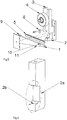
- Fig. 4 shows a front and side views of the tensioner
- Fig. 5 shows a perspective view of tensioner's components
- Fig. 6 shows a perspective view of a slide of the tensioner.
- the automatic strand, belt, chain, etc. tensioner consists of the following components: a slide 2 ( Fig. 6 ) shifting along a first guideway 3, whose axis is supported with bearings, a tensioner pulley 4, and a key 1, which causes shifting and blocking of the slide 2.
- the first guideway 3 with the slide 2 is fitted to a casing of a device in which the tensioner has been applied.
- a second guideway 2a for the key 1 At the lower part of the slide 2 there is a second guideway 2a for the key 1.
- the second guideway 2a has an indent 2b, whose bearing surface is tilted towards the direction of the shift at an angle ⁇ that is equal to an angle of the mutual tilt of the working surfaces 10 and 11 of the key 1.
- the angle between the working surfaces 10 and 11 of the key 1 ranges from 3 to 20 degrees, depending on the specific features and parameters of the device in which the tensioner has been applied.
- the key 1 has a protrusion 9 on its broader end. The protrusion 9 cooperates with the edge of the first guideway 3 and restricts key shifting.
- the key 1 is placed in the guideway 2a, and the lower working surface of the key 11 touches the Indent surface 2b, and its upper working surface 10 rests upon the lower surface of the first guideway 3.
- the slide 2 is tightly fitted on the belt, which blocks it from upward shifting and prevents slacking.
- the force F which affects the key 1, causes the key's shifting along the direction of the force, which causes the slide 2 downward shifting, and eliminates the slack.
- the tension of the rope on both pulleys 7 and 8 within the system is regulated steplessly, which prevents the slide's backward motion and reoccurrence of slack.
- the slide cannot move backward thanks to the system's self-locking features, and in certain applications thanks to the additional use of a ratchet toothed bar 5 which cooperates with a movable pawl 6.
- the slide shifts smoothly and in both directions, while in the solution according to the present invention the shift occurs only in one direction.
Landscapes
- Engineering & Computer Science (AREA)
- General Engineering & Computer Science (AREA)
- Mechanical Engineering (AREA)
- Devices For Conveying Motion By Means Of Endless Flexible Members (AREA)
Claims (4)
- Un tendeur de brin, de courroie ou de chaîne automatique qui déplace une poulie tendeuse (4) entre une poulie motrice d'entraînement (7, 8) et une poulie alimentée (7, 8), le tendeur comprenant une glissière (2) à laquelle la poulie tendeuse (4) est fixée et qui se déplace le long d'une première voie de guidage (3) adaptée à un boîtier, et un composant par lequel la glissière (2) avec la poulie tendeuse (4) est déplacée, caractérisé en ce que- la glissière (2) présente à sa partie inférieure une deuxième voie de guidage (2a) avec un creux (2b), dont la surface d'appui est inclinée vers une direction du déplacement, - le composant par lequel la glissière (2) avec la poulie tendeuse (4) est déplacée constitue une clé (1) ayant des surfaces de travail supérieure et inférieure inclinées mutuellement (10, 11), où un angle entre les surfaces de travail (10, 11) de la clé (1) est égal à un angle d'inclinaison de la surface d'appui du creux (2b) :
dans lequel- la clé (1) coopère avec la première voie de guidage (3) et la deuxième voie de guidage (2a) de telle sorte que la surface supérieure (10) de la clé (1) repose sur une surface inférieure de la première voie de guidage (3), tandis que la surface inférieure (11) de la clé (1) touche la surface d'appui du creux (2b) ; et- sous une force constante (F) exercée sur la clé (1), par exemple par un ressort, la clé (1) est adaptée pour se déplacer selon une direction de la force (F) et la glissière (2) avec la poulie tendeuse (4) est adaptée pour se déplacer vers le bas. - Le tendeur selon la revendication 1, caractérisé en ce que l'angle entre les surfaces de travail (10) et (11) de la clé (1) est compris entre 3 et 20 degrés.
- Le tendeur selon la revendication 1, caractérisé en ce que la clé (1) est pourvue d'une saillie (9) sur son extrémité la plus large, qui coopère avec le bord de la première voie de guidage (3) et limite le déplacement de la clé.
- Le tendeur selon la revendication 1, caractérisé en ce que la clé (1) est en outre pourvue d'une barre dentée à cliquet (5) sur sa surface latérale, tandis que la première voie de guidage (3) est pourvue d'un cliquet mobile (6) qui coopère avec la barre dentée à cliquet (5) de la clé (1).
Applications Claiming Priority (1)
| Application Number | Priority Date | Filing Date | Title |
|---|---|---|---|
| PL408597A PL223981B1 (pl) | 2014-06-17 | 2014-06-17 | Automatyczny napinacz |
Publications (2)
| Publication Number | Publication Date |
|---|---|
| EP2990688A1 EP2990688A1 (fr) | 2016-03-02 |
| EP2990688B1 true EP2990688B1 (fr) | 2021-02-17 |
Family
ID=53673881
Family Applications (1)
| Application Number | Title | Priority Date | Filing Date |
|---|---|---|---|
| EP15460026.6A Not-in-force EP2990688B1 (fr) | 2014-06-17 | 2015-06-17 | Tendeur automatique |
Country Status (2)
| Country | Link |
|---|---|
| EP (1) | EP2990688B1 (fr) |
| PL (1) | PL223981B1 (fr) |
Families Citing this family (1)
| Publication number | Priority date | Publication date | Assignee | Title |
|---|---|---|---|---|
| CN106402295A (zh) * | 2016-08-24 | 2017-02-15 | 咸阳蓝博机械有限公司 | 一种外置式直线运动模组 |
Family Cites Families (5)
| Publication number | Priority date | Publication date | Assignee | Title |
|---|---|---|---|---|
| GB9718408D0 (en) | 1997-09-01 | 1997-11-05 | Ontario Drive & Gear Limited | Automatic chain tensioner |
| US2469296A (en) * | 1944-03-24 | 1949-05-03 | Sydney T Farrell | Belt driving mechanism |
| FR1166119A (fr) * | 1956-12-04 | 1958-11-03 | Sedis Transmissions Mec | Tendeur automatique de chaîne |
| US3978737A (en) * | 1975-08-27 | 1976-09-07 | Xerox Corporation | Chain tensioning device |
| JP2003294095A (ja) | 2002-04-04 | 2003-10-15 | Kawasaki Heavy Ind Ltd | ラチェット式自動テンショナ |
-
2014
- 2014-06-17 PL PL408597A patent/PL223981B1/pl unknown
-
2015
- 2015-06-17 EP EP15460026.6A patent/EP2990688B1/fr not_active Not-in-force
Non-Patent Citations (1)
| Title |
|---|
| None * |
Also Published As
| Publication number | Publication date |
|---|---|
| PL223981B1 (pl) | 2016-11-30 |
| EP2990688A1 (fr) | 2016-03-02 |
| PL408597A1 (pl) | 2015-12-21 |
Similar Documents
| Publication | Publication Date | Title |
|---|---|---|
| US3812733A (en) | Tensioning device for flexible members | |
| US20190329842A1 (en) | Chain guide assembly | |
| EP1990267A3 (fr) | Dérailleur arrière à profil bas avec guide-câble | |
| WO2015196268A8 (fr) | Ensemble tendeur orbital | |
| WO2006078890B1 (fr) | Courroie de transport a entrainement direct et a faible frottement | |
| US20110256971A1 (en) | Chain Tensioner | |
| US20080185263A1 (en) | Travelator and method for controlling the operation of a travelator | |
| EP2990688B1 (fr) | Tendeur automatique | |
| KR970027965A (ko) | 동력 전달 벨트용 인장기 | |
| RU2013150966A (ru) | Устройство натяжения цепи | |
| US20060249356A1 (en) | Lifter device | |
| US520827A (en) | Reversible traversing movement | |
| US8888626B2 (en) | Tensioning system with self-locking mechanism | |
| CN104343909A (zh) | 链条引导机构 | |
| US6685052B1 (en) | Feeding apparatus for chip component | |
| JP2006256817A (ja) | 乗客コンベヤの移動手摺駆動装置 | |
| JP2018531851A (ja) | ハンドレールを駆動するための装置 | |
| JP2010168149A (ja) | マンコンベアステップチェーンテンション調整装置 | |
| JP5618696B2 (ja) | 乗客コンベア | |
| US20100258664A1 (en) | Cable guide tensioner for regulator system | |
| RU51149U1 (ru) | Натяжное устройство передачи гибкой связью | |
| CN112539257A (zh) | 传动条的张紧结构 | |
| KR100357544B1 (ko) | 자동차용 타이밍 벨트 텐셔너 장치 | |
| WO2009019849A1 (fr) | Courroie trapézoïdale pour transmission de puissance à charge élevée | |
| EP1602773A3 (fr) | Dispositif pour ajuster la tension d' une courroie de transmission. |
Legal Events
| Date | Code | Title | Description |
|---|---|---|---|
| PUAI | Public reference made under article 153(3) epc to a published international application that has entered the european phase |
Free format text: ORIGINAL CODE: 0009012 |
|
| AK | Designated contracting states |
Kind code of ref document: A1 Designated state(s): AL AT BE BG CH CY CZ DE DK EE ES FI FR GB GR HR HU IE IS IT LI LT LU LV MC MK MT NL NO PL PT RO RS SE SI SK SM TR |
|
| AX | Request for extension of the european patent |
Extension state: BA ME |
|
| 17P | Request for examination filed |
Effective date: 20160427 |
|
| RBV | Designated contracting states (corrected) |
Designated state(s): AL AT BE BG CH CY CZ DE DK EE ES FI FR GB GR HR HU IE IS IT LI LT LU LV MC MK MT NL NO PL PT RO RS SE SI SK SM TR |
|
| GRAP | Despatch of communication of intention to grant a patent |
Free format text: ORIGINAL CODE: EPIDOSNIGR1 |
|
| STAA | Information on the status of an ep patent application or granted ep patent |
Free format text: STATUS: GRANT OF PATENT IS INTENDED |
|
| INTG | Intention to grant announced |
Effective date: 20191217 |
|
| GRAS | Grant fee paid |
Free format text: ORIGINAL CODE: EPIDOSNIGR3 |
|
| GRAA | (expected) grant |
Free format text: ORIGINAL CODE: 0009210 |
|
| STAA | Information on the status of an ep patent application or granted ep patent |
Free format text: STATUS: THE PATENT HAS BEEN GRANTED |
|
| AK | Designated contracting states |
Kind code of ref document: B1 Designated state(s): AL AT BE BG CH CY CZ DE DK EE ES FI FR GB GR HR HU IE IS IT LI LT LU LV MC MK MT NL NO PL PT RO RS SE SI SK SM TR |
|
| REG | Reference to a national code |
Ref country code: GB Ref legal event code: FG4D |
|
| REG | Reference to a national code |
Ref country code: CH Ref legal event code: EP |
|
| REG | Reference to a national code |
Ref country code: DE Ref legal event code: R096 Ref document number: 602015065540 Country of ref document: DE |
|
| REG | Reference to a national code |
Ref country code: AT Ref legal event code: REF Ref document number: 1361888 Country of ref document: AT Kind code of ref document: T Effective date: 20210315 |
|
| REG | Reference to a national code |
Ref country code: IE Ref legal event code: FG4D |
|
| REG | Reference to a national code |
Ref country code: LT Ref legal event code: MG9D |
|
| REG | Reference to a national code |
Ref country code: NL Ref legal event code: MP Effective date: 20210217 |
|
| PG25 | Lapsed in a contracting state [announced via postgrant information from national office to epo] |
Ref country code: PT Free format text: LAPSE BECAUSE OF FAILURE TO SUBMIT A TRANSLATION OF THE DESCRIPTION OR TO PAY THE FEE WITHIN THE PRESCRIBED TIME-LIMIT Effective date: 20210617 Ref country code: LT Free format text: LAPSE BECAUSE OF FAILURE TO SUBMIT A TRANSLATION OF THE DESCRIPTION OR TO PAY THE FEE WITHIN THE PRESCRIBED TIME-LIMIT Effective date: 20210217 Ref country code: NO Free format text: LAPSE BECAUSE OF FAILURE TO SUBMIT A TRANSLATION OF THE DESCRIPTION OR TO PAY THE FEE WITHIN THE PRESCRIBED TIME-LIMIT Effective date: 20210517 Ref country code: BG Free format text: LAPSE BECAUSE OF FAILURE TO SUBMIT A TRANSLATION OF THE DESCRIPTION OR TO PAY THE FEE WITHIN THE PRESCRIBED TIME-LIMIT Effective date: 20210517 Ref country code: HR Free format text: LAPSE BECAUSE OF FAILURE TO SUBMIT A TRANSLATION OF THE DESCRIPTION OR TO PAY THE FEE WITHIN THE PRESCRIBED TIME-LIMIT Effective date: 20210217 Ref country code: GR Free format text: LAPSE BECAUSE OF FAILURE TO SUBMIT A TRANSLATION OF THE DESCRIPTION OR TO PAY THE FEE WITHIN THE PRESCRIBED TIME-LIMIT Effective date: 20210518 Ref country code: FI Free format text: LAPSE BECAUSE OF FAILURE TO SUBMIT A TRANSLATION OF THE DESCRIPTION OR TO PAY THE FEE WITHIN THE PRESCRIBED TIME-LIMIT Effective date: 20210217 |
|
| REG | Reference to a national code |
Ref country code: AT Ref legal event code: MK05 Ref document number: 1361888 Country of ref document: AT Kind code of ref document: T Effective date: 20210217 |
|
| PG25 | Lapsed in a contracting state [announced via postgrant information from national office to epo] |
Ref country code: LV Free format text: LAPSE BECAUSE OF FAILURE TO SUBMIT A TRANSLATION OF THE DESCRIPTION OR TO PAY THE FEE WITHIN THE PRESCRIBED TIME-LIMIT Effective date: 20210217 Ref country code: RS Free format text: LAPSE BECAUSE OF FAILURE TO SUBMIT A TRANSLATION OF THE DESCRIPTION OR TO PAY THE FEE WITHIN THE PRESCRIBED TIME-LIMIT Effective date: 20210217 Ref country code: NL Free format text: LAPSE BECAUSE OF FAILURE TO SUBMIT A TRANSLATION OF THE DESCRIPTION OR TO PAY THE FEE WITHIN THE PRESCRIBED TIME-LIMIT Effective date: 20210217 Ref country code: PL Free format text: LAPSE BECAUSE OF FAILURE TO SUBMIT A TRANSLATION OF THE DESCRIPTION OR TO PAY THE FEE WITHIN THE PRESCRIBED TIME-LIMIT Effective date: 20210217 Ref country code: SE Free format text: LAPSE BECAUSE OF FAILURE TO SUBMIT A TRANSLATION OF THE DESCRIPTION OR TO PAY THE FEE WITHIN THE PRESCRIBED TIME-LIMIT Effective date: 20210217 |
|
| PG25 | Lapsed in a contracting state [announced via postgrant information from national office to epo] |
Ref country code: IS Free format text: LAPSE BECAUSE OF FAILURE TO SUBMIT A TRANSLATION OF THE DESCRIPTION OR TO PAY THE FEE WITHIN THE PRESCRIBED TIME-LIMIT Effective date: 20210617 |
|
| PG25 | Lapsed in a contracting state [announced via postgrant information from national office to epo] |
Ref country code: AT Free format text: LAPSE BECAUSE OF FAILURE TO SUBMIT A TRANSLATION OF THE DESCRIPTION OR TO PAY THE FEE WITHIN THE PRESCRIBED TIME-LIMIT Effective date: 20210217 Ref country code: SM Free format text: LAPSE BECAUSE OF FAILURE TO SUBMIT A TRANSLATION OF THE DESCRIPTION OR TO PAY THE FEE WITHIN THE PRESCRIBED TIME-LIMIT Effective date: 20210217 Ref country code: EE Free format text: LAPSE BECAUSE OF FAILURE TO SUBMIT A TRANSLATION OF THE DESCRIPTION OR TO PAY THE FEE WITHIN THE PRESCRIBED TIME-LIMIT Effective date: 20210217 Ref country code: CZ Free format text: LAPSE BECAUSE OF FAILURE TO SUBMIT A TRANSLATION OF THE DESCRIPTION OR TO PAY THE FEE WITHIN THE PRESCRIBED TIME-LIMIT Effective date: 20210217 |
|
| REG | Reference to a national code |
Ref country code: DE Ref legal event code: R097 Ref document number: 602015065540 Country of ref document: DE |
|
| PG25 | Lapsed in a contracting state [announced via postgrant information from national office to epo] |
Ref country code: RO Free format text: LAPSE BECAUSE OF FAILURE TO SUBMIT A TRANSLATION OF THE DESCRIPTION OR TO PAY THE FEE WITHIN THE PRESCRIBED TIME-LIMIT Effective date: 20210217 Ref country code: SK Free format text: LAPSE BECAUSE OF FAILURE TO SUBMIT A TRANSLATION OF THE DESCRIPTION OR TO PAY THE FEE WITHIN THE PRESCRIBED TIME-LIMIT Effective date: 20210217 Ref country code: DK Free format text: LAPSE BECAUSE OF FAILURE TO SUBMIT A TRANSLATION OF THE DESCRIPTION OR TO PAY THE FEE WITHIN THE PRESCRIBED TIME-LIMIT Effective date: 20210217 Ref country code: ES Free format text: LAPSE BECAUSE OF FAILURE TO SUBMIT A TRANSLATION OF THE DESCRIPTION OR TO PAY THE FEE WITHIN THE PRESCRIBED TIME-LIMIT Effective date: 20210217 |
|
| PLBE | No opposition filed within time limit |
Free format text: ORIGINAL CODE: 0009261 |
|
| STAA | Information on the status of an ep patent application or granted ep patent |
Free format text: STATUS: NO OPPOSITION FILED WITHIN TIME LIMIT |
|
| REG | Reference to a national code |
Ref country code: DE Ref legal event code: R119 Ref document number: 602015065540 Country of ref document: DE |
|
| 26N | No opposition filed |
Effective date: 20211118 |
|
| PG25 | Lapsed in a contracting state [announced via postgrant information from national office to epo] |
Ref country code: AL Free format text: LAPSE BECAUSE OF FAILURE TO SUBMIT A TRANSLATION OF THE DESCRIPTION OR TO PAY THE FEE WITHIN THE PRESCRIBED TIME-LIMIT Effective date: 20210217 Ref country code: MC Free format text: LAPSE BECAUSE OF FAILURE TO SUBMIT A TRANSLATION OF THE DESCRIPTION OR TO PAY THE FEE WITHIN THE PRESCRIBED TIME-LIMIT Effective date: 20210217 |
|
| REG | Reference to a national code |
Ref country code: CH Ref legal event code: PL |
|
| GBPC | Gb: european patent ceased through non-payment of renewal fee |
Effective date: 20210617 |
|
| PG25 | Lapsed in a contracting state [announced via postgrant information from national office to epo] |
Ref country code: SI Free format text: LAPSE BECAUSE OF FAILURE TO SUBMIT A TRANSLATION OF THE DESCRIPTION OR TO PAY THE FEE WITHIN THE PRESCRIBED TIME-LIMIT Effective date: 20210217 |
|
| REG | Reference to a national code |
Ref country code: BE Ref legal event code: MM Effective date: 20210630 |
|
| PG25 | Lapsed in a contracting state [announced via postgrant information from national office to epo] |
Ref country code: LU Free format text: LAPSE BECAUSE OF NON-PAYMENT OF DUE FEES Effective date: 20210617 |
|
| PG25 | Lapsed in a contracting state [announced via postgrant information from national office to epo] |
Ref country code: LI Free format text: LAPSE BECAUSE OF NON-PAYMENT OF DUE FEES Effective date: 20210630 Ref country code: IT Free format text: LAPSE BECAUSE OF FAILURE TO SUBMIT A TRANSLATION OF THE DESCRIPTION OR TO PAY THE FEE WITHIN THE PRESCRIBED TIME-LIMIT Effective date: 20210217 Ref country code: IE Free format text: LAPSE BECAUSE OF NON-PAYMENT OF DUE FEES Effective date: 20210617 Ref country code: GB Free format text: LAPSE BECAUSE OF NON-PAYMENT OF DUE FEES Effective date: 20210617 Ref country code: DE Free format text: LAPSE BECAUSE OF NON-PAYMENT OF DUE FEES Effective date: 20220101 Ref country code: CH Free format text: LAPSE BECAUSE OF NON-PAYMENT OF DUE FEES Effective date: 20210630 |
|
| PG25 | Lapsed in a contracting state [announced via postgrant information from national office to epo] |
Ref country code: IS Free format text: LAPSE BECAUSE OF FAILURE TO SUBMIT A TRANSLATION OF THE DESCRIPTION OR TO PAY THE FEE WITHIN THE PRESCRIBED TIME-LIMIT Effective date: 20210617 Ref country code: FR Free format text: LAPSE BECAUSE OF NON-PAYMENT OF DUE FEES Effective date: 20210630 |
|
| PG25 | Lapsed in a contracting state [announced via postgrant information from national office to epo] |
Ref country code: BE Free format text: LAPSE BECAUSE OF NON-PAYMENT OF DUE FEES Effective date: 20210630 |
|
| PG25 | Lapsed in a contracting state [announced via postgrant information from national office to epo] |
Ref country code: HU Free format text: LAPSE BECAUSE OF FAILURE TO SUBMIT A TRANSLATION OF THE DESCRIPTION OR TO PAY THE FEE WITHIN THE PRESCRIBED TIME-LIMIT; INVALID AB INITIO Effective date: 20150617 |
|
| PG25 | Lapsed in a contracting state [announced via postgrant information from national office to epo] |
Ref country code: CY Free format text: LAPSE BECAUSE OF FAILURE TO SUBMIT A TRANSLATION OF THE DESCRIPTION OR TO PAY THE FEE WITHIN THE PRESCRIBED TIME-LIMIT Effective date: 20210217 |
|
| PG25 | Lapsed in a contracting state [announced via postgrant information from national office to epo] |
Ref country code: MK Free format text: LAPSE BECAUSE OF FAILURE TO SUBMIT A TRANSLATION OF THE DESCRIPTION OR TO PAY THE FEE WITHIN THE PRESCRIBED TIME-LIMIT Effective date: 20210217 |
|
| PG25 | Lapsed in a contracting state [announced via postgrant information from national office to epo] |
Ref country code: TR Free format text: LAPSE BECAUSE OF FAILURE TO SUBMIT A TRANSLATION OF THE DESCRIPTION OR TO PAY THE FEE WITHIN THE PRESCRIBED TIME-LIMIT Effective date: 20210217 |
|
| PG25 | Lapsed in a contracting state [announced via postgrant information from national office to epo] |
Ref country code: MT Free format text: LAPSE BECAUSE OF FAILURE TO SUBMIT A TRANSLATION OF THE DESCRIPTION OR TO PAY THE FEE WITHIN THE PRESCRIBED TIME-LIMIT Effective date: 20210217 |