EP2990708A1 - Coupling system for connecting two fluid conducting elements - Google Patents
Coupling system for connecting two fluid conducting elements Download PDFInfo
- Publication number
- EP2990708A1 EP2990708A1 EP15171315.3A EP15171315A EP2990708A1 EP 2990708 A1 EP2990708 A1 EP 2990708A1 EP 15171315 A EP15171315 A EP 15171315A EP 2990708 A1 EP2990708 A1 EP 2990708A1
- Authority
- EP
- European Patent Office
- Prior art keywords
- coupling
- locking
- coupling system
- coupling body
- longitudinal direction
- Prior art date
- Legal status (The legal status is an assumption and is not a legal conclusion. Google has not performed a legal analysis and makes no representation as to the accuracy of the status listed.)
- Granted
Links
Images


Classifications
-
- F—MECHANICAL ENGINEERING; LIGHTING; HEATING; WEAPONS; BLASTING
- F16—ENGINEERING ELEMENTS AND UNITS; GENERAL MEASURES FOR PRODUCING AND MAINTAINING EFFECTIVE FUNCTIONING OF MACHINES OR INSTALLATIONS; THERMAL INSULATION IN GENERAL
- F16L—PIPES; JOINTS OR FITTINGS FOR PIPES; SUPPORTS FOR PIPES, CABLES OR PROTECTIVE TUBING; MEANS FOR THERMAL INSULATION IN GENERAL
- F16L37/00—Couplings of the quick-acting type
- F16L37/08—Couplings of the quick-acting type in which the connection between abutting or axially overlapping ends is maintained by locking members
- F16L37/10—Couplings of the quick-acting type in which the connection between abutting or axially overlapping ends is maintained by locking members using a rotary external sleeve or ring on one part
- F16L37/101—Couplings of the quick-acting type in which the connection between abutting or axially overlapping ends is maintained by locking members using a rotary external sleeve or ring on one part in which the coupling is coaxial with the pipe
-
- F—MECHANICAL ENGINEERING; LIGHTING; HEATING; WEAPONS; BLASTING
- F02—COMBUSTION ENGINES; HOT-GAS OR COMBUSTION-PRODUCT ENGINE PLANTS
- F02M—SUPPLYING COMBUSTION ENGINES IN GENERAL WITH COMBUSTIBLE MIXTURES OR CONSTITUENTS THEREOF
- F02M35/00—Combustion-air cleaners, air intakes, intake silencers, or induction systems specially adapted for, or arranged on, internal-combustion engines
- F02M35/10—Air intakes; Induction systems
- F02M35/10091—Air intakes; Induction systems characterised by details of intake ducts: shapes; connections; arrangements
- F02M35/10144—Connections of intake ducts to each other or to another device
-
- F—MECHANICAL ENGINEERING; LIGHTING; HEATING; WEAPONS; BLASTING
- F16—ENGINEERING ELEMENTS AND UNITS; GENERAL MEASURES FOR PRODUCING AND MAINTAINING EFFECTIVE FUNCTIONING OF MACHINES OR INSTALLATIONS; THERMAL INSULATION IN GENERAL
- F16L—PIPES; JOINTS OR FITTINGS FOR PIPES; SUPPORTS FOR PIPES, CABLES OR PROTECTIVE TUBING; MEANS FOR THERMAL INSULATION IN GENERAL
- F16L2201/00—Special arrangements for pipe couplings
- F16L2201/10—Indicators for correct coupling
Definitions
- the invention relates to a coupling system for connecting two media-carrying elements according to the preamble of claim 1.
- Coupling systems for hoses for transporting media, in particular fluid media (liquids), have long been known.
- these coupling systems are used to seal the hose with e.g. to connect an aggregate.
- a connecting piece is arranged at one end of the hose, which can be connected on the opposite side with a nozzle of the unit.
- the connection between the hose-side connector and the unit-side nozzle is usually secured with a retaining spring or locking spring, which engages from the outside through the connector behind a collection of the nozzle and thus blocks the axial movement.
- the DE 100 55 348 A1 relates to a hose connection having an inner sleeve in which a hose end is pressed, an outer sleeve which is arranged around the inner sleeve and connected to another hose or an aggregate, and securing means for fixing the assembled sleeves.
- This securing means may be a locking spring which engages through gaps in the outer sleeve behind the highlights of the inner sleeve and thus blocks an axial movement of the two sleeves against each other.
- Such coupling systems e.g. The companies HENN GmbH & Co KG or NORMA Group SE or the VDA (Verband der Automobilindustrie eV) are also referred to as plug connection systems or quick couplings. These are e.g. used in the automotive industry for hose connections or pipe applications in the intercooler and cooling water sector.
- the components of these coupling systems may be made entirely of metal or partly of metal and partly of plastic.
- a disadvantage of the known coupling systems that the coupling between the hose and unit with multiple handles in the assembly is to produce. This is due in particular to the handling of the securing spring, which constitutes a separate component of the coupling system.
- the retaining spring With the correct opening in place over the assembled sleeves and then push radially through the outer sleeve to secure the two sleeves against each other.
- This can be difficult and expensive, especially with narrow mounting spaces between the engine components.
- the safety spring can be lost during assembly or even at the time of delivery and provision.
- An object of the present invention is to provide a coupling system of the type described above, which allows a quick and easy mounting of the coupling system with simple and precise locking and a minimum of required components.
- the present invention relates to a coupling system according to the preamble of claim 1, wherein the engagement member of the locking body by a rotational movement between the first position, in which the engagement member is positioned outside the interior of the coupling body, and the second position, in which Engagement element extends through the recess radially into the interior of the coupling body, can be moved.
- connection body takes place in the coupling body by a rotational movement of the locking body.
- the locking body is in the first position in a rotational position, so that its engagement member releases the connector body in the coupling body, and in the second position in a rotational position, so that its engagement member blocks the connector body in the coupling body in the longitudinal direction.
- the connection body can be part of an aggregate and the coupling body can be connected to a hose end or a pipe end, both preferably made of plastic.
- This rotational movement represents a simple assembly handle, which leads to a simple and secure locking.
- the coupling body and the locking body By using the coupling body and the locking body, the number of components of the coupling system is minimized, which reduces costs and simplifies handling. In this way, a compact system is provided, which can also be used in tight mounting spaces and handled comparatively well.
- the coupling system according to the invention also allows for minimal forces and stresses in the coupling body as well as in the connecting body under load both in the radial and in the axial direction. These forces and stresses are inventively absorbed by the locking body due to its geometry at the joining surfaces. At the same time the locking body ensures the sealing of the coupling system, which can be done by means of an inner sealing element.
- the rotational movement is preferably as short as possible in order to simplify assembly and increase the stability of the connection, and is preferably in an angular range between 40 ° and 20 °, more preferably at about 28 °.
- the locking body has a plurality of engagement elements, more preferably three engagement elements, which are arranged distributed uniformly over the circumference, that are offset by 120 ° to each other.
- the coupling body has a corresponding number of recess. As a result, the holding forces are distributed more uniformly on the coupling body or locking body and thereby improves the durability of the coupling connection.
- the engagement element in the second position, protrudes radially into the interior of the coupling body so far through the recess that the engagement element can block the connection body received in the first coupling area in the longitudinal direction. This can be done by pressing the engagement element radially from the outside onto the connection body and thereby blocking it non-positively. Alternatively or additionally, this blockage can be made in a form-fitting manner by placing the engagement element behind a corresponding radial elevation, such as, for example. a bead of the connecting body engages.
- the engagement element in the second position can engage radially behind a first radial elevation of the connection body received in the first coupling region and block in the longitudinal direction.
- the locking body is closed in a ring shape. This increases the durability of the coupling connection, because a closed ring body can absorb higher forces. Also, a closed ring body is less likely to get lost because it can only be removed by axial movements in the longitudinal direction of the coupling body.
- the coupling body has a first radial protrusion which blocks movement of the locking body in the longitudinal direction in at least one direction.
- This radial projection may be a web which is only partially formed in the circumferential direction, or a closed web-shaped ring which is completely formed in the circumferential direction. It can too a plurality of first radial projections may be provided, which are arranged offset in the circumferential direction against each other on the same circumference. This radial elevation limits the possibilities of movement of the locking body in at least one direction along the longitudinal axis and thus allows a certain pre-positioning of the locking body for assembly. At the same time it serves as a captive.
- the coupling body further includes a second radial protrusion which blocks movement of the locking body in the longitudinal direction in a further direction, so that the locking body is movable in the longitudinal direction only between the first radial protrusion and the second radial protrusion.
- This second radial elevation may correspond to the first radial elevation or be configured differently.
- the two radial elevations may be in the longitudinal direction partially or directly opposite or circumferentially offset from each other. It is also possible for a plurality of second radial elevations to be provided, which are arranged offset from one another in the circumferential direction on the same circumference.
- the combination of the two radial elevations of the axial movement of the locking body can be determined limited so that its exact axial position can be defined. As a result, the locking body can be prepositioned very accurately for the assembly and for its locking effect.
- the second radial protrusion is arranged in the first coupling region and positioned such that it can block the rotational movement of the locking body in at least one direction. This can be done in that the second radial projection can come into contact with one side of the engagement element and then prevents further rotational movement. In this way, the degree of rotational movement of the engagement element, ie its angle, be limited in a predetermined manner. This function can alternatively be exercised by another separate element.
- the locking body is connected via a spring element with the engagement element.
- This allows the radial suspension of the engagement element between the first position and the second position.
- spring forces are exerted radially on the engagement element in such a way that, during the rotational movement from the first to the second position, it pushes itself autonomously through the recess of the coupling body into its interior.
- the spring forces are achieved by stresses in the material, so that other elements can be omitted, which simplifies the manufacture and assembly and thus made cheaper.
- the engagement member in the first position, may be radially urged away from the clutch body.
- the necessary tension is built up in the spring elements in order to press the engagement element through the recess of the coupling body into its interior during the rotational movement into the second position.
- no or only a small spring force is required because the engagement member is then engaged with the connector body.
- recesses are provided in the locking body to increase its spring action or to achieve the same spring action in a longitudinally more compact design of the locking body.
- the engagement element has an oblique edge which extends both radially and in the circumferential direction and which can come into contact with the coupling body, so that the engagement element in the rotational movement via the contact between the coupling body and its oblique edge can be pushed radially resiliently from the coupling body.
- the coupling body may have a corresponding corresponding oblique edge.
- the engagement element slides during the rotational movement along the (oblique) edge of the recess of the coupling body, so that transmitted via this contact and the spring force of the spring element, the rotational movement of the locking body in a radial engagement of its engagement element can be.
- the spring element can be moved over its oblique edge solely by the rotational movement from the second position back to the first position at the (oblique) edge of the coupling body out of the recess.
- the coupling body has a first marking element and the locking body has a second marking element, which in the second position of the rotational movement in the longitudinal direction can directly opposite each other.
- These marking elements can be formed in color and / or by shaping on the surface of the coupling body or locking body. They serve to optically control the second position of the rotational movement as a locking position (locking position) of the coupling system. In other words, if the two marking elements lie exactly opposite one another in the longitudinal direction, this indicates visually that the coupling system is locked, i. the Arret istsflower is taken.
- the coupling body has a recess and the locking body on a survey, so that in the second position of the rotational movement, the survey engage in the recess and block the rotation or make it difficult.
- the achieved second position of the rotational movement can be secured as a locking position of the coupling system in the form of a detent position, so that this connection can not be solved at all or only with increased effort again.
- the depression or elevation can be provided by engraving or shaping of the coupling body or locking body.
- the coupling body and the locking body are made of plastic. This reduces the weight and the cost of these bodies. At the same time, this can extend the life of the coupling system due to better absorption of static and dynamic loads.
- the coupling body has a second coupling region with a second radial elevation and / or a profiling.
- This second coupling region serves to connect the coupling body to a hose.
- the coupling body in this second coupling region have a radial elevation in the form of a circumferentially partially or continuously formed bead as the second radial elevation over which the hose is pushed during assembly.
- the tube may then be e.g. be fastened by means of a hose clamp between the bead and the remaining coupling body to this, wherein the bead can prevent slipping of the hose.
- a clamping ring or a Kunststoffumspritzung or plastic welding can be provided.
- the coupling body in this second coupling region can be profiled e.g. have in the form of a corrugation or a sawtooth profile, which increases the frictional resistance of the surface of the coupling body and thereby also counteract a withdrawal of the hose.
- the coupling body preferably has a conical transition region between the first coupling region and the second coupling region, the diameter of which decreases from the first coupling region to the second coupling region.
- the coupling body can be made smaller and more compact in diameter, because the coupling body receives in its first coupling region the connecting body in its interior and in its second coupling region, the hose from the outside.
- a sealing member is disposed inside the coupling body for sealing between the coupling body and the terminal body.
- the sealing element may be an O-ring or a 2-lip system, which may be annularly closed in the circumferential direction. It may consist of a silicone-like or thermoplastic material or have such.
- the sealing element can be secured against axial displacement with a locking element, which is also closed in the circumferential direction annular can be trained.
- the blocking element is preferably designed as a plastic part and welded or injected inside the coupling body.
- Fig. 1 shows a perspective schematic representation of a coupling system 10, 20 according to the invention.
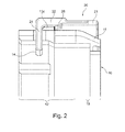
- Fig. 2 shows a schematic sectional view of a portion of the coupling system 10, 20 according to the invention.
- the coupling system 10, 20 has a coupling element 10, which may also be referred to as a coupling housing 10, and a locking element 20, which may also be referred to as a locking ring 20.
- the coupling element 10 and the locking element 20 are formed substantially cylindrical or annularly closed, are made of plastic and extend along a common longitudinal axis L.
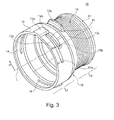
- Fig. 3 shows a perspective schematic representation of a coupling element 10 according to the invention.
- the coupling element 10 has a coupling body 11.
- the coupling body 11 has a first coupling region 12 and a second coupling region 16.
- the first coupling portion 12 serves to receive a Connection element 30 of an aggregate (see. Fig. 5 ).
- the connection element 30 may be an aggregate connection 30, for example based on the VDA standard, or a connector 30.
- the second coupling portion 16 serves to receive a hose or pipe, in particular made of plastic (not shown).
- the first coupling portion 12 is surrounded annularly by the locking element 20.
- the first coupling region 12 and the second coupling region 16 are connected by a conical transition region 19, the diameter of the coupling body 11 decreasing from the first coupling region 12 to the second coupling region 16.
- the coupling body 11 has in its first coupling portion 12 has three recesses 14 which extend in the form of grooves 14 in the circumferential direction.
- the recesses 14 are arranged distributed equidistantly in the circumferential direction, i. offset by 120 °, and connect the interior of the coupling body 11 with its external environment.
- Each recess 14 has an oblique edge 14 a, which extends in both the circumferential direction and in the radial direction R, and a vertical edge 14 b, which extends only in the radial direction R.
- the coupling body 11 also has a first radial elevation 13a as the first securing element 13a, which extends radially outwards from the conical transition area 19.
- the coupling body 11 also has a second radial elevation 13b as a second securing element 13b, which extends radially outward in the first coupling region 12 and is positioned in the circumferential direction such that it lies directly opposite the first radial elevation 13a in the longitudinal direction L.
- the coupling body 11 also has third radial elevations 13c as third securing elements 13c, which extend in the circumferential direction directly along the recesses 14 from their second edges 14b to approximately the middle of the recesses 14.
- the coupling body 11 further comprises a first marking element 15a, which is mounted on its surface visible from the outside and extends in the longitudinal direction L.
- the coupling body 11 At its second coupling region 16, the coupling body 11 has a second radial elevation 17 in the form of a bead 17 which extends closed in the circumferential direction. Between the bead 17 and the conical transition region 19, the coupling body 11 has a profiling 18 in the form of a corrugation 18.
- the bead 17 and the corrugation 18 serve to receive a plugged hose (not shown) and are intended to effect by increasing the frictional forces, so that the hose can not be deducted from the coupling body 11.
- the hose can be secured to the corrugation 18 by means of a press ring, a hose clamp or a plastic extrusion.
- a plastic pipe can also be welded directly to the conical transition region 19, so that the second coupling region 16 with corrugation 18 and bead 17 can be dispensed with.
- Fig. 4 shows a perspective schematic representation of a locking element 20 according to the invention.
- the locking element 20 has an annular locking body 21. Of the locking body 21 extend in the longitudinal direction L three spring elements 22, which may also be referred to as webs 22. The spring elements 22 are partially separated in the circumferential direction by extending in the longitudinal direction L columns 23 from the locking body 21. The spring elements 22 have at their opposite end of the locking body 21 an engagement element 24, which may also be referred to as a nose 24 or hook 24 and which extends radially inwardly.
- Each engagement element 24 has in the circumferential direction on one side an oblique edge 26 and on the opposite side a vertical edge 27.
- each engagement element 24 On its outer side, each engagement element 24 has a second marking element 25a, which is visually recognizable from the outside and which extends in the longitudinal direction L.
- each engagement element 24 On its inner side, each engagement element 24 has a first elevation 28 extending in the circumferential direction and extending radially inward in the form of a first edge 28.
- Each first elevation 28 has a radially inward-pointing second elevation 25b in the form of a second edge 25b, which extends in the longitudinal direction L and the oblique edge 26, the engagement element 24 in the longitudinal direction L is arranged opposite.
- the coupling element 10 and the locking element 20 cooperate as follows (cf. Fig. 1 ):
- the locking body 21 is disposed in the first coupling portion 12 of the coupling body 11 around this.
- the locking body 21 in the axial direction, i. positioned and held in the longitudinal direction L between the first radial elevation 13a and the second radial elevation 13b of the coupling body 11, so that axial displacements are not at all or at most minimally possible.
- This positioning is done such that the engagement members 24 and the recesses 14 are on the same circumference.
- In the circumferential direction of the locking body 21 is movable relative to the coupling body 11 by a rotational movement.
- the engagement element 24 are located outside the recesses 14 or within the recesses 14, but without protruding into the interior of the coupling body 11.
- the engagement members 24 are located outside of the recesses 14 so that they are pressed against the coupling body 11.
- the spring elements 22 are resiliently tensioned.
- the interior of the coupling body 11 is free of the engagement element 24, so that a connection element 30 (cf. Fig. 5 ) can be inserted into the first coupling portion 12.
- the locking body 21 is rotated clockwise in the direction of the tube in such a way that its engagement element 24 is guided into the recesses 14 and behind a first radial elevation 32 of the latter Connection body 31 of the connection element 30 (see. Fig. 5 ) and this block form-locking in the longitudinal direction L.
- the engagement element 24 are pressed by the spring force of the tensioned spring elements 22 radially inwardly through the recesses 14 therethrough.
- the oblique edges 26 of the engagement elements 24 and the corresponding oblique edges 14a of the slide Recesses 14 from each other until the engagement elements 24 have fully engaged in the recesses 14.
- the rotational movement ends when the vertical edges 27 of the engagement elements 24 abut against the vertical edges 14b of the recesses 14.
- the connecting element 30 is blocked by the coupling system 10, 20 longitudinal direction L.
- the second position of the rotational movement as a locking position or locking position engage the second elevation 25b of the spring elements 22 in the corresponding recesses 15b of the coupling body 11, so that the second position of the rotational movement only with increased force against the latched in the recesses 15b surveys 25b and the spring action of the spring elements 22 can solve again.
- the first marking element 15 a and the second marking element 25a exactly opposite, so that from the outside, the secured second position of the rotational movement can be optically detected.
- the engagement elements 24 and the first protrusions 28 of the spring elements 22 enclose the third radial elevations 13c in the longitudinal direction L from both sides.
- the play between recesses 14 and engagement elements 24 can be minimized and the stability of the securing of the connection element 30 can be increased.
- a release of this compound of the coupling system 10, 20 is still possible by rotational movement.
- serve the oblique edges 26 of the engagement elements 24 and the oblique edges 14b of the recesses 14, on which the engagement elements 24 are moved by a rotational movement from the viewing direction of the hose counterclockwise back to the first position of the rotational movement out of the recesses 24 out can.
- Fig. 5 shows a schematic sectional view of the coupling system 10, 20 according to the invention with connection element 30.
- the connection body 31 of Connecting element 30 (VDA connecting piece 30) is thereby secured by the engagement elements 24 in the interior of the coupling body 11.
- the engagement elements 24 engage behind the first radial elevation 32 of the connection body 31, which can also be referred to as the first bead 32.
- the connecting body 31 abuts with its end and / or with its first radial elevation 32 in the longitudinal direction L against the interior of the coupling body 11.
- the connecting body 31 further comprises a second radial elevation 33rd in the form of a second bead 33 which is arranged opposite the engagement elements 24 in the longitudinal direction L such that the first radial elevation 32 and the second radial elevation 33 in the secured second position enclose the engagement elements 24 in the longitudinal direction L on both sides.
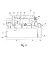
- Fig. 6 shows a part of the Fig. 5 ,
- a sealing element 40 is shown, which is formed as an O-ring or as a 2-lip system and is arranged radially between the inside of the coupling body 11 and the outside of the connection body 31, around these two bodies 11 , 31 fluid-tight seal against each other.
- a blocking element 50 in the form of a locking ring 50 is provided, which bears radially on the inside of the coupling body 11 and secures the sealing element 40 in the longitudinal direction L.
- the blocking element 50 is welded or molded onto the coupling body 11 as a plastic part.
Landscapes
- Engineering & Computer Science (AREA)
- General Engineering & Computer Science (AREA)
- Mechanical Engineering (AREA)
- Quick-Acting Or Multi-Walled Pipe Joints (AREA)
Abstract
Die vorliegende Erfindung betrifft ein Kupplungssystem (10, 20) zur Verbindung zweier medienführender Elemente mit einem Kupplungskörper (11), welcher einen ersten Kupplungsbereich (12) zur Aufnahme eines Anschlusskörpers (31) eines medienführenden Elementes in seinem Inneren aufweist, und einem Verriegelungskörper (21), welcher zumindest teilweise im ersten Kupplungsbereich (12) um den Kupplungskörper (11) herum angeordnet ist, wobei der Kupplungskörper (11) in seinem ersten Kupplungsbereich (12) wenigstens eine Ausnehmung (14) aufweist und wobei der Verriegelungskörper (21) wenigstens ein Eingriffselement (24) aufweist, welches in einer ersten Position außerhalb des Inneren des Kupplungskörpers (11) positioniert ist und in einer zweiten Position durch die Ausnehmung (14) hindurch radial in das Innere des Kupplungskörpers (11) hineinragt: Das Kupplungssystem (10, 20) ist dadurch gekennzeichnet, dass das Eingriffselement (24) durch eine Drehbewegung zwischen der ersten Position und der zweiten Position bewegt werden kann.The present invention relates to a coupling system (10, 20) for connecting two media-carrying elements to a coupling body (11), which has a first coupling region (12) for receiving a connecting body (31) of a media-carrying element in its interior, and a locking body (21 ), which is arranged at least partially in the first coupling region (12) around the coupling body (11), wherein the coupling body (11) in its first coupling region (12) has at least one recess (14) and wherein the locking body (21) at least one Engaging element (24) which is positioned in a first position outside the interior of the coupling body (11) and in a second position through the recess (14) radially into the interior of the coupling body (11) protrudes: The coupling system (10, 20 ) is characterized in that the engagement element (24) by a rotational movement between the first pos ion and the second position can be moved.
Description
Die Erfindung betrifft ein Kupplungssystem zur Verbindung zweier medienführender Elemente gemäß dem Oberbegriff des Anspruchs 1.The invention relates to a coupling system for connecting two media-carrying elements according to the preamble of claim 1.
Es sind seit langem Kupplungssysteme für Schläuche zum Transport von Medien, insbesondere von fluiden Medien (Flüssigkeiten), bekannt. Üblicherweise werden diese Kupplungssysteme dazu verwendet, den Schlauch mit z.B. einem Aggregat zu verbinden. Hierzu wird an einem Ende des Schlauches ein Verbindungsstück angeordnet, welches an der gegenüberliegenden Seite mit einem Stutzen des Aggregats verbunden werden kann. Die Verbindung zwischen dem schlauchseitigen Verbindungsstück und dem aggregatseitigen Stutzen wird üblicherweise mit einer Haltefeder oder Sicherungsfeder gesichert, welche von außen durch das Verbindungsstück hindurch hinter eine Erhebung des Stutzens greift und so die axiale Bewegung blockiert.Coupling systems for hoses for transporting media, in particular fluid media (liquids), have long been known. Usually, these coupling systems are used to seal the hose with e.g. to connect an aggregate. For this purpose, a connecting piece is arranged at one end of the hose, which can be connected on the opposite side with a nozzle of the unit. The connection between the hose-side connector and the unit-side nozzle is usually secured with a retaining spring or locking spring, which engages from the outside through the connector behind a collection of the nozzle and thus blocks the axial movement.
Die
Derartige Kupplungssysteme z.B. der Firmen HENN GmbH & Co KG oder NORMA Group SE oder des VDA (Verband der Automobilindustrie e. V.) werden auch als Steckverbindungssysteme oder Schnellkupplungen bezeichnet. Diese werden z.B. in der Automobilindustrie bei Schlauchverbindungen oder Rohranwendungen im Ladeluft- und Kühlwasserbereich eingesetzt. Die Komponenten dieser Kupplungssysteme können vollständig aus Metall bestehen oder teilweise aus Metall und teilweise aus Kunststoff.Such coupling systems e.g. The companies HENN GmbH & Co KG or NORMA Group SE or the VDA (Verband der Automobilindustrie eV) are also referred to as plug connection systems or quick couplings. These are e.g. used in the automotive industry for hose connections or pipe applications in the intercooler and cooling water sector. The components of these coupling systems may be made entirely of metal or partly of metal and partly of plastic.
Nachteilig ist bei den bekannten Kupplungssystemen, dass die Kupplung zwischen Schlauch und Aggregat mit mehreren Handgriffen in der Montage herzustellen ist. Dies ist insbesondere durch die Handhabung der Sicherungsfeder bedingt, welche ein separates Bauteil des Kupplungssystems darstellt. So ist die Sicherungsfeder mit der richtigen Öffnung an der richtigen Stelle über die zusammengefügten Hülsen zu positionieren und dann radial durch die äußere Hülse hindurch zu drücken, um die beiden Hülsen gegeneinander zu sichern. Dies kann gerade bei engen Montageräumen zwischen den Motorkomponenten schwierig und aufwendig sein. Ferner kann die Sicherungsfeder bei der Montage bzw. schon bei der Anlieferung und Bereitstellung verloren gehen.A disadvantage of the known coupling systems that the coupling between the hose and unit with multiple handles in the assembly is to produce. This is due in particular to the handling of the securing spring, which constitutes a separate component of the coupling system. Thus, position the retaining spring with the correct opening in place over the assembled sleeves and then push radially through the outer sleeve to secure the two sleeves against each other. This can be difficult and expensive, especially with narrow mounting spaces between the engine components. Furthermore, the safety spring can be lost during assembly or even at the time of delivery and provision.
Eine Aufgabe der vorliegenden Erfindung ist es, ein Kupplungssystem der eingangs beschriebenen Art bereit zu stellen, welches ein schnelles und einfaches Montieren des Kupplungssystems mit einfacher und präziser Verriegelung sowie einem Minimum erforderlicher Komponenten ermöglicht.An object of the present invention is to provide a coupling system of the type described above, which allows a quick and easy mounting of the coupling system with simple and precise locking and a minimum of required components.
Die Aufgabe wird erfindungsgemäß durch ein Kupplungssystem mit den Merkmalen gemäß Anspruch 1 gelöst. Vorteilhafte Weiterbildungen sind in den Unteransprüchen beschrieben.The object is achieved by a coupling system with the features of claim 1. Advantageous developments are described in the subclaims.
Somit betrifft die vorliegende Erfindung ein Kupplungssystem gemäß dem Oberbegriff des Anspruchs 1, wobei das Eingriffselement des Verriegelungskörpers durch eine Drehbewegung zwischen der ersten Position, in der das Eingriffselement außerhalb des Inneren des Kupplungskörpers positioniert ist, und der zweiten Position, in der das Eingriffselement durch die Ausnehmung hindurch radial in das Innere des Kupplungskörpers hineinragt, bewegt werden kann.Thus, the present invention relates to a coupling system according to the preamble of claim 1, wherein the engagement member of the locking body by a rotational movement between the first position, in which the engagement member is positioned outside the interior of the coupling body, and the second position, in which Engagement element extends through the recess radially into the interior of the coupling body, can be moved.
Mit anderen Worten erfolgt das Verriegeln bzw. das Lösen des Anschlusskörpers in dem Kupplungskörper durch eine Drehbewegung des Verriegelungskörpers. Dabei befindet sich der Verriegelungskörper in der ersten Position in einer Drehstellung, so dass sein Eingriffselement den Anschlusskörper im Kupplungskörper freigibt, und in der zweiten Position in einer Drehstellung, so dass sein Eingriffselement den Anschlusskörper im Kupplungskörper in Längsrichtung blockiert. Der Anschlusskörper kann Bestandteil eines Aggregats und der Kupplungskörper kann mit einem Schlauchende oder einem Rohrende, beides vorzugsweise aus Kunststoff, verbunden sein.In other words, the locking or the release of the connection body takes place in the coupling body by a rotational movement of the locking body. In this case, the locking body is in the first position in a rotational position, so that its engagement member releases the connector body in the coupling body, and in the second position in a rotational position, so that its engagement member blocks the connector body in the coupling body in the longitudinal direction. The connection body can be part of an aggregate and the coupling body can be connected to a hose end or a pipe end, both preferably made of plastic.
Diese Drehbewegung stellt einen einfachen Montagehandgriff dar, der zu einer einfachen und sicheren Verriegelung führt. Durch die Verwendung des Kupplungskörpers und des Verriegelungskörpers wird die Anzahl der Komponenten des Kupplungssystems minimiert, was die Kosten reduziert und die Handhabung vereinfacht. Auf diese Weise wird auch ein kompaktes System bereitgestellt, welches auch in engen Montageräumen eingesetzt und vergleichsweise gut gehandhabt werden kann. Auch lässt das erfindungsgemäße Kupplungssystem unter Belastung sowohl in radialer als auch in axialer Richtung minimale Kräfte und Spannungen in dem Kupplungskörper sowie in dem Anschlusskörper zu. Diese Kräfte und Spannungen werden erfindungsgemäß von dem Verriegelungskörper aufgrund seiner Geometrie an den Fügeflächen aufgenommen. Gleichzeitig sichert der Verriegelungskörper die Abdichtung des Kupplungssystems, welche mittels eines innenliegenden Dichtungselementes erfolgen kann. Die Drehbewegung erfolgt vorzugsweise möglichst kurz, um die Montage zu vereinfachen und die Stabilität der Verbindung zu erhöhen, und liegt vorzugsweise in einem Winkelbereich zwischen 40° und 20°, besonders bevorzugt bei ungefähr 28°.This rotational movement represents a simple assembly handle, which leads to a simple and secure locking. By using the coupling body and the locking body, the number of components of the coupling system is minimized, which reduces costs and simplifies handling. In this way, a compact system is provided, which can also be used in tight mounting spaces and handled comparatively well. The coupling system according to the invention also allows for minimal forces and stresses in the coupling body as well as in the connecting body under load both in the radial and in the axial direction. These forces and stresses are inventively absorbed by the locking body due to its geometry at the joining surfaces. At the same time the locking body ensures the sealing of the coupling system, which can be done by means of an inner sealing element. The rotational movement is preferably as short as possible in order to simplify assembly and increase the stability of the connection, and is preferably in an angular range between 40 ° and 20 °, more preferably at about 28 °.
Vorzugsweise weist der Verriegelungskörper mehrere Eingriffselemente, besonders bevorzugt drei Eingriffselemente, auf, die gleichmäßig über den Umfang verteilt angeordnet sind, d.h. um 120° zueinander versetzt sind. Der Kupplungskörper weist eine entsprechende Anzahl von Ausnehmung auf. Hierdurch werden die Haltekräfte gleichmäßiger auf den Kupplungskörper bzw. Verriegelungskörper verteilt und hierdurch die Haltbarkeit der Kupplungsverbindung verbessert.Preferably, the locking body has a plurality of engagement elements, more preferably three engagement elements, which are arranged distributed uniformly over the circumference, that are offset by 120 ° to each other. The coupling body has a corresponding number of recess. As a result, the holding forces are distributed more uniformly on the coupling body or locking body and thereby improves the durability of the coupling connection.
Gemäß einem Aspekt der vorliegenden Erfindung ragt das Eingriffselement in der zweiten Position soweit durch die Ausnehmung radial in das Innere des Kupplungskörpers hinein, dass das Eingriffselement den im ersten Kupplungsbereich aufgenommenen Anschlusskörper in Längsrichtung blockieren kann. Dies kann dadurch erfolgen, dass das Eingriffselement radial von außen auf den Anschlusskörper drückt und diesen dadurch kraftschlüssig blockiert. Alternativ oder zusätzlich kann diese Blockade formschlüssig erfolgen, indem das Eingriffselement hinter eine entsprechende radiale Erhebung wie z.B. einen Wulst des Anschlusskörpers greift.According to one aspect of the present invention, in the second position, the engagement element protrudes radially into the interior of the coupling body so far through the recess that the engagement element can block the connection body received in the first coupling area in the longitudinal direction. This can be done by pressing the engagement element radially from the outside onto the connection body and thereby blocking it non-positively. Alternatively or additionally, this blockage can be made in a form-fitting manner by placing the engagement element behind a corresponding radial elevation, such as, for example. a bead of the connecting body engages.
Gemäß einem weiteren Aspekt der vorliegenden Erfindung kann das Eingriffselement in der zweiten Position radial hinter eine erste radiale Erhebung des im ersten Kupplungsbereich aufgenommenen Anschlusskörpers greifen und in Längsrichtung blockieren. Dies ist vorteilhaft, weil diese Art der formschlüssigen Verbindung mit einfacheren Mitteln höhere Kräfte aushalten kann und hierdurch eine haltbarere und sicherere Verbindung darstellt als eine kraftschlüssige Verbindung.According to a further aspect of the present invention, the engagement element in the second position can engage radially behind a first radial elevation of the connection body received in the first coupling region and block in the longitudinal direction. This is advantageous because this type of positive connection with simpler means can withstand higher forces and thereby represents a more durable and safer connection than a non-positive connection.
Gemäß einem weiteren Aspekt der vorliegenden Erfindung ist der Verriegelungskörper geschlossen ringförmig ausgebildet. Dies erhöht die Haltbarkeit der Kupplungsverbindung, weil ein geschlossener Ringkörper höhere Kräfte aufnehmen kann. Auch kann ein geschlossener Ringkörper weniger leicht verloren gehen, weil er nur noch durch axiale Bewegungen in Längsrichtung von dem Kupplungskörper entfernt werden kann.According to a further aspect of the present invention, the locking body is closed in a ring shape. This increases the durability of the coupling connection, because a closed ring body can absorb higher forces. Also, a closed ring body is less likely to get lost because it can only be removed by axial movements in the longitudinal direction of the coupling body.
Gemäß einem weiteren Aspekt der vorliegenden Erfindung weist der Kupplungskörper eine erste radiale Erhebung auf, welche eine Bewegung des Verriegelungskörpers in Längsrichtung in wenigstens einer Richtung blockiert. Diese radiale Erhebung kann ein Steg sein, der nur teilweise in Umfangsrichtung ausgebildet ist, oder ein geschlossener stegförmiger Ring, der vollständig in Umfangsrichtung ausgebildet ist. Es können auch mehrere erste radiale Erhebungen vorgesehen sein, die in Umfangsrichtung gegeneinander versetzt auf dem gleichen Umfang angeordnet sind. Diese radiale Erhebung schränkt die Bewegungsmöglichkeiten des Verriegelungskörpers in wenigstens eine Richtung entlang der Längsachse ein und ermöglicht so eine gewisse Vorpositionierung des Verriegelungskörpers für die Montage. Sie dient dadurch gleichzeitig als Verliersicherung.According to another aspect of the present invention, the coupling body has a first radial protrusion which blocks movement of the locking body in the longitudinal direction in at least one direction. This radial projection may be a web which is only partially formed in the circumferential direction, or a closed web-shaped ring which is completely formed in the circumferential direction. It can too a plurality of first radial projections may be provided, which are arranged offset in the circumferential direction against each other on the same circumference. This radial elevation limits the possibilities of movement of the locking body in at least one direction along the longitudinal axis and thus allows a certain pre-positioning of the locking body for assembly. At the same time it serves as a captive.
Gemäß einem weiteren Aspekt der vorliegenden Erfindung weist der Kupplungskörper ferner eine zweite radiale Erhebung auf, welche eine Bewegung des Verriegelungskörpers in Längsrichtung in einer weiteren Richtung blockiert, so dass der Verriegelungskörper in Längsrichtung lediglich zwischen der ersten radialen Erhebung und der zweiten radialen Erhebung beweglich ist. Diese zweite radiale Erhebung kann der ersten radialen Erhebung entsprechen oder andersartig ausgestaltet sein. Die beiden radialen Erhebungen können einander in Längsrichtung teilweise oder direkt gegenüber liegen oder in Umfangsrichtung gegeneinander versetzt angeordnet sein. Es können auch mehrere zweite radiale Erhebungen vorgesehen sein, die in Umfangsrichtung gegeneinander versetzt auf dem gleichen Umfang angeordnet sind. Durch die Kombination der beiden radialen Erhebungen kann der axiale Bewegungsspielraum des Verriegelungskörpers vorbestimmt derart eingeschränkt werden, dass seine genaue axiale Position definiert werden kann. Hierdurch kann der Verriegelungskörper sehr genau für die Montage sowie für seine Verriegelungswirkung vorpositioniert werden.According to another aspect of the present invention, the coupling body further includes a second radial protrusion which blocks movement of the locking body in the longitudinal direction in a further direction, so that the locking body is movable in the longitudinal direction only between the first radial protrusion and the second radial protrusion. This second radial elevation may correspond to the first radial elevation or be configured differently. The two radial elevations may be in the longitudinal direction partially or directly opposite or circumferentially offset from each other. It is also possible for a plurality of second radial elevations to be provided, which are arranged offset from one another in the circumferential direction on the same circumference. The combination of the two radial elevations of the axial movement of the locking body can be determined limited so that its exact axial position can be defined. As a result, the locking body can be prepositioned very accurately for the assembly and for its locking effect.
Gemäß einem weiteren Aspekt der vorliegenden Erfindung ist die zweite radiale Erhebung im ersten Kupplungsbereich angeordnet und derart positioniert, dass sie die Drehbewegung des Verriegelungskörpers in zumindest einer Richtung blockieren kann. Dies kann dadurch erfolgen, dass die zweite radiale Erhebung mit einer Seite des Eingriffselements in Kontakt kommen kann und dann eine weitere Drehbewegung verhindert. Hierdurch kann das Maß der Drehbewegung des Eingriffselementes, d.h. dessen Winkel, vorbestimmt eingeschränkt werden. Diese Funktion kann alternativ auch durch ein weiteres separates Element ausgeübt werden.According to a further aspect of the present invention, the second radial protrusion is arranged in the first coupling region and positioned such that it can block the rotational movement of the locking body in at least one direction. This can be done in that the second radial projection can come into contact with one side of the engagement element and then prevents further rotational movement. In this way, the degree of rotational movement of the engagement element, ie its angle, be limited in a predetermined manner. This function can alternatively be exercised by another separate element.
Gemäß einem weiteren Aspekt der vorliegenden Erfindung ist der Verriegelungskörper über ein Federelement mit dem Eingriffselement verbunden. Dies ermöglicht die radiale Federung des Eingriffselementes zwischen der ersten Position und der zweiten Position. Hierbei werden Federkräfte radial auf das Eingriffselement derart ausgeübt, dass sich dieses bei der Drehbewegung aus der ersten in die zweite Position selbstständig durch die Ausnehmung des Kupplungskörpers in dessen Innere hineindrückt. Die Federkräfte werden durch Spannungen im Material erreicht, so dass auch weitere Elemente verzichtet werden kann, was die Herstellung und Montage vereinfacht und dadurch günstiger gestaltet.According to a further aspect of the present invention, the locking body is connected via a spring element with the engagement element. This allows the radial suspension of the engagement element between the first position and the second position. In this case, spring forces are exerted radially on the engagement element in such a way that, during the rotational movement from the first to the second position, it pushes itself autonomously through the recess of the coupling body into its interior. The spring forces are achieved by stresses in the material, so that other elements can be omitted, which simplifies the manufacture and assembly and thus made cheaper.
Gemäß einem weiteren Aspekt der vorliegenden Erfindung kann das Eingriffselement in der ersten Position von dem Kupplungskörper radial federnd weggedrückt werden. Hierdurch wird die nötige Spannung in dem Federelemente aufgebaut, um bei der Drehbewegung in die zweite Position das Eingriffselement durch die Ausnehmung des Kupplungskörpers hindurch in dessen Inneres hinein zu drücken. In der zweiten Position ist keine bzw. lediglich eine geringe Federkraft erforderlich, weil sich das Eingriffselement dann im Eingriff mit dem Anschlusskörper befindet. Vorzugsweise werden in Umfangsrichtung beidseitig des Federelements in Längsrichtung verlaufende Aussparungen im Verriegelungskörper vorgesehen, um dessen Federwirkung zu erhöhen bzw. die gleiche Federwirkung bei einer in Längsrichtung kompakteren Ausführung des Verriegelungskörpers zu erreichen.According to another aspect of the present invention, in the first position, the engagement member may be radially urged away from the clutch body. As a result, the necessary tension is built up in the spring elements in order to press the engagement element through the recess of the coupling body into its interior during the rotational movement into the second position. In the second position, no or only a small spring force is required because the engagement member is then engaged with the connector body. Preferably in the circumferential direction on both sides of the spring element extending in the longitudinal direction recesses are provided in the locking body to increase its spring action or to achieve the same spring action in a longitudinally more compact design of the locking body.
Gemäß einem weiteren Aspekt der vorliegenden Erfindung weist das Eingriffselement eine schräge Kante auf, welche sich sowohl radial als auch in Umfangsrichtung erstreckt und welche mit dem Kupplungskörper in Kontakt kommen kann, so dass das Eingriffselement bei der Drehbewegung über den Kontakt zwischen Kupplungskörper und seiner schrägen Kante von dem Kupplungskörper radial federnd weggedrückt werden kann. Der Kupplungskörper kann eine entsprechende korrespondierende schräge Kante aufweisen. An seiner schrägen Kante gleitet das Eingriffselement bei der Drehbewegung an der (schrägen) Kante der Ausnehmung des Kupplungskörpers entlang, so dass über diesen Kontakt sowie die Federkraft des Federelements die Drehbewegung des Verriegelungskörpers in ein radiales Eingreifen seines Eingriffselementes übertragen werden kann. Im umgekehrten Fall des Lösens der Kupplungsverbindung kann das Federelement über seine schräge Kante alleinig durch die Drehbewegung aus der zweiten Position zurück in die erste Position an der (schrägen) Kante des Kupplungskörpers aus der Ausnehmung heraus bewegt werden.According to a further aspect of the present invention, the engagement element has an oblique edge which extends both radially and in the circumferential direction and which can come into contact with the coupling body, so that the engagement element in the rotational movement via the contact between the coupling body and its oblique edge can be pushed radially resiliently from the coupling body. The coupling body may have a corresponding corresponding oblique edge. At its oblique edge, the engagement element slides during the rotational movement along the (oblique) edge of the recess of the coupling body, so that transmitted via this contact and the spring force of the spring element, the rotational movement of the locking body in a radial engagement of its engagement element can be. In the reverse case of releasing the coupling connection, the spring element can be moved over its oblique edge solely by the rotational movement from the second position back to the first position at the (oblique) edge of the coupling body out of the recess.
Gemäß einem weiteren Aspekt der vorliegenden Erfindung weist der Kupplungskörper ein erstes Markierungselement und der Verriegelungskörper ein zweites Markierungselement auf, welche in der zweiten Position der Drehbewegung in Längsrichtung einander direkt gegenüberliegen können. Diese Markierungselemente können farblich und bzw. oder durch Formgebung an der Oberfläche des Kupplungskörpers bzw. Verriegelungskörpers ausgebildet sein. Sie dienen der optischen Kontrolle der zweiten Position der Drehbewegung als Verriegelungsposition (Arretierungsposition) des Kupplungssystems. Liegen sich, mit anderen Worten, die beiden Markierungselemente in Längsrichtung genau gegenüber, so wird hierdurch visuell angezeigt, dass das Kupplungssystem verriegelt ist, d.h. der Arretierungszustand eingenommen ist.According to a further aspect of the present invention, the coupling body has a first marking element and the locking body has a second marking element, which in the second position of the rotational movement in the longitudinal direction can directly opposite each other. These marking elements can be formed in color and / or by shaping on the surface of the coupling body or locking body. They serve to optically control the second position of the rotational movement as a locking position (locking position) of the coupling system. In other words, if the two marking elements lie exactly opposite one another in the longitudinal direction, this indicates visually that the coupling system is locked, i. the Arretierungszustand is taken.
Gemäß einem weiteren Aspekt der vorliegenden Erfindung weist der Kupplungskörper eine Vertiefung und der Verriegelungskörper eine Erhebung auf, so dass in der zweiten Position der Drehbewegung die Erhebung in die Vertiefung eingreifen und die Drehbewegung blockieren oder erschweren kann. Hierdurch kann die erreichte zweite Position der Drehbewegung als Verriegelungsposition des Kupplungssystems in Form einer Raststellung gesichert werden, damit sich diese Verbindung gar nicht mehr bzw. nur mit erhöhtem Kraftaufwand wieder lösen lässt. Dies sichert die Kupplungsfunktion des Kupplungssystems. Die Vertiefung bzw. Erhebung kann durch eine Gravierung oder Formgebung des Kupplungskörpers bzw. Verriegelungskörpers vorgesehen sein.According to a further aspect of the present invention, the coupling body has a recess and the locking body on a survey, so that in the second position of the rotational movement, the survey engage in the recess and block the rotation or make it difficult. In this way, the achieved second position of the rotational movement can be secured as a locking position of the coupling system in the form of a detent position, so that this connection can not be solved at all or only with increased effort again. This ensures the coupling function of the coupling system. The depression or elevation can be provided by engraving or shaping of the coupling body or locking body.
Gemäß einem weiteren Aspekt der vorliegenden Erfindung sind der Kupplungskörper und der Verriegelungskörper aus Kunststoff. Dies reduziert das Gewicht und die Kosten dieser Körper. Gleichzeitig lässt sich hierdurch die Lebensdauer des Kupplungssystems aufgrund besserer Aufnahme statischer und dynamischer Belastungen verlängern.According to another aspect of the present invention, the coupling body and the locking body are made of plastic. This reduces the weight and the cost of these bodies. At the same time, this can extend the life of the coupling system due to better absorption of static and dynamic loads.
Gemäß einem weiteren Aspekt der vorliegenden Erfindung weist der Kupplungskörper einen zweiten Kupplungsbereich mit einer zweiten radialen Erhebung und bzw. oder einer Profilierung auf. Dieser zweite Kupplungsbereich dient dem Anschluss des Kupplungskörpers an einen Schlauch. Hierzu kann der Kupplungskörper in diesem zweiten Kupplungsbereich eine radiale Erhebung in Form eines in Umfangsrichtung teilweise oder durchgehend ausgebildeten Wulstes als zweite radiale Erhebung aufweisen, über den der Schlauch bei der Montage geschoben wird. Der Schlauch kann dann z.B. mittels einer Schlauchschelle zwischen Wulst und übrigem Kupplungskörper an diesem befestigt werden, wobei der Wulst ein Abrutschen des Schlauches verhindern kann. Anstelle einer Schlauchschelle kann auch ein Klemmring oder eine Kunststoffumspritzung oder Kunststoffschweißung vorgesehen werden. Alternativ oder zusätzlich kann der Kupplungskörper in diesem zweiten Kupplungsbereich eine Profilierung z.B. in Form einer Riffelung oder eines Sägezahnprofils aufweisen, die den Reibwiderstand der Oberfläche des Kupplungskörpers erhöht und hierdurch ebenfalls einem Abziehen des Schlauches entgegenwirken kann.According to a further aspect of the present invention, the coupling body has a second coupling region with a second radial elevation and / or a profiling. This second coupling region serves to connect the coupling body to a hose. For this purpose, the coupling body in this second coupling region have a radial elevation in the form of a circumferentially partially or continuously formed bead as the second radial elevation over which the hose is pushed during assembly. The tube may then be e.g. be fastened by means of a hose clamp between the bead and the remaining coupling body to this, wherein the bead can prevent slipping of the hose. Instead of a hose clamp, a clamping ring or a Kunststoffumspritzung or plastic welding can be provided. Alternatively or additionally, the coupling body in this second coupling region can be profiled e.g. have in the form of a corrugation or a sawtooth profile, which increases the frictional resistance of the surface of the coupling body and thereby also counteract a withdrawal of the hose.
Vorzugsweise weist der Kupplungskörper zwischen dem ersten Kupplungsbereich und dem zweiten Kupplungsbereich einen konischen Übergangsbereich auf, dessen Durchmesser sich vom ersten Kupplungsbereich zum zweiten Kupplungsbereich hin verringert. Hierdurch kann der Kupplungskörper im Durchmesser kleiner und kompakter ausgebildet werden, weil der Kupplungskörper in seinem ersten Kupplungsbereich den Anschlusskörper in seinem Inneren und in seinem zweiten Kupplungsbereich den Schlauch von außen aufnimmt.The coupling body preferably has a conical transition region between the first coupling region and the second coupling region, the diameter of which decreases from the first coupling region to the second coupling region. As a result, the coupling body can be made smaller and more compact in diameter, because the coupling body receives in its first coupling region the connecting body in its interior and in its second coupling region, the hose from the outside.
Gemäß einem weiteren Aspekt der vorliegenden Erfindung ist im Inneren des Kupplungskörpers ein Dichtungselement zum Abdichten zwischen dem Kupplungskörper und dem Anschlusskörpers angeordnet. Das Dichtungselement kann ein O-Ring oder ein 2-Lippen-System sein, welches in Umfangsrichtung geschlossen ringförmig ausgebildet sein kann. Es kann aus eine silikonartigen oder thermoplastischen Material bestehen bzw. ein solches aufweisen. Das Dichtungselement kann gegen axiale Verschiebung mit einem Sperrelement gesichert sein, welches ebenfalls in Umfangsrichtung geschlossen ringförmig ausgebildet sein kann. Das Sperrelement ist vorzugsweise als Kunststoffteil ausgebildet und im Inneren des Kupplungskörpers eingeschweißt oder eingespritzt.According to another aspect of the present invention, a sealing member is disposed inside the coupling body for sealing between the coupling body and the terminal body. The sealing element may be an O-ring or a 2-lip system, which may be annularly closed in the circumferential direction. It may consist of a silicone-like or thermoplastic material or have such. The sealing element can be secured against axial displacement with a locking element, which is also closed in the circumferential direction annular can be trained. The blocking element is preferably designed as a plastic part and welded or injected inside the coupling body.
Ein Ausführungsbeispiel und weitere Vorteile der Erfindung werden nachstehend im Zusammenhang mit den folgenden Figuren erläutert. Darin zeigt:
- Fig. 1
- eine perspektivische schematische Darstellung eines erfindungsgemäßen Kupplungssystems;
- Fig. 2
- eine schematische Schnittdarstellung eines Teilbereichs des erfindungsgemäßen Kupplungssystems;
- Fig. 3
- eine perspektivische schematische Darstellung eines erfindungsgemäßen Kupplungselements;
- Fig. 4
- eine perspektivische schematische Darstellung eines erfindungsgemäßen Verriegelungselements;
- Fig. 5
- eine schematische Schnittdarstellung des erfindungsgemäßen Kupplungssystems mit Anschlusselement; und
- Fig. 6
- einen Ausschnitt der
Fig. 5 .
- Fig. 1
- a perspective schematic view of a coupling system according to the invention;
- Fig. 2
- a schematic sectional view of a portion of the coupling system according to the invention;
- Fig. 3
- a perspective schematic representation of a coupling element according to the invention;
- Fig. 4
- a perspective schematic representation of a locking element according to the invention;
- Fig. 5
- a schematic sectional view of the coupling system according to the invention with connection element; and
- Fig. 6
- a section of the
Fig. 5 ,
Der Kupplungskörper 11 weist in seinem ersten Kupplungsbereich 12 drei Ausnehmungen 14 auf, die in Form von Nuten 14 in Umfangsrichtung verlaufen. Die Ausnehmungen 14 sind in Umfangsrichtung äquidistant verteilt angeordnet, d.h. um 120° versetzt, und verbinden das Innere des Kupplungskörper 11 mit seiner äußeren Umgebung. Jede Ausnehmung 14 weist eine schräge Kante 14a auf, welche sich sowohl in Umfangsrichtung als auch in radiale Richtung R erstreckt, sowie eine senkrechte Kante 14b, welche sich lediglich in radiale Richtung R erstreckt.The
Der Kupplungskörper 11 weist ferner eine erste radiale Erhebung 13a als erstes Sicherungselement 13a auf, welche sich vom konischen Übergangsbereich 19 radial nach außen erstreckt. Der Kupplungskörper 11 weist ferner eine zweite radiale Erhebung 13b als zweite Sicherungselement 13b auf, welche sich im erste Kupplungsbereich 12 radial nach außen erstreckt und in Umfangsrichtung derart positioniert ist, dass sie der ersten radialen Erhebung 13a in Längsrichtung L direkt gegenüberliegt. Der Kupplungskörper 11 weist ebenfalls dritte radiale Erhebungen 13c als dritte Sicherungselemente 13c auf, welche sich in Umfangsrichtung direkt entlang der Ausnehmungen 14 von deren zweiten Kanten 14b bis etwa zur Mitte der Ausnehmungen 14 erstrecken. Diese dritten radialen Erhebungen 13c weisen jeweils eine Vertiefung 15b in Form einer Einkerbung 15b oder Rille 15b auf, die sich in Längsrichtung L erstreckt. Der Kupplungskörper 11 weist ferner ein erstes Markierungselement 15a auf, welches auf seiner Oberfläche von außen sichtbar angebracht ist und sich in Längsrichtung L erstreckt.The
An seinem zweiten Kupplungsbereich 16 weist der Kupplungskörper 11 eine zweite radiale Erhebung 17 in Form einer Wulst 17 auf, die sich in Umfangsrichtung geschlossen erstreckt. Zwischen der Wulst 17 und dem konischen Übergangsbereich 19 weist der Kupplungskörper 11 eine Profilierung 18 in Form einer Riffelung 18 auf. Die Wulst 17 und die Riffelung 18 dienen der Aufnahme eines aufgesteckten Schlauches (nicht dargestellt) und sollen durch die Erhöhung der Reibkräfte bewirken, so dass der Schlauch sich nicht vom Kupplungskörper 11 abziehen lässt. Hierzu kann der Schlauch auf der Riffelung 18 mittels eines Pressrings, einer Schlauchschelle oder einer Kunststoffumspritzung gesichert werden. Alternativ kann ein Kunststoffrohr auch direkt an den konischen Übergangsbereich 19 angeschweißt werden, so dass der zweite Kupplungsbereich 16 mit Riffelung 18 und Wulst 17 entfallen kann.At its
Jedes Eingriffselement 24 weist in Umfangsrichtung auf einer Seite eine schräge Kante 26 und auf der gegenüberliegenden Seite eine senkrechte Kante 27 auf. An seiner Außenseite weist jedes Eingriffselement 24 ein zweites Markierungselement 25a auf, welches von außen optisch erkennbar ist und welches sich in Längsrichtung L erstreckt. Auf seiner Innenseite weist jedes Eingriffselement 24 eine in Umfangsrichtung verlaufende und sich radial nach innen erstreckende erste Erhebung 28 in Form einer erste Kante 28 auf. Jeder erste Erhebung 28 weist eine radial nach innen zeigende zweite Erhebung 25b in Form einer zweite Kante 25b auf, welche sich in Längsrichtung L erstreckt und der schrägen Kante 26 das Eingriffselement 24 in Längsrichtung L gegenüberliegend angeordnet ist.Each
Das Kupplungselement 10 und das Verriegelungselement 20 wirken wie folgt zusammen (vgl. insbesondere
Der Verriegelungskörper 21 ist im ersten Kupplungsbereich 12 des Kupplungskörpers 11 um diesen herum angeordnet. Hierbei wird der Verriegelungskörper 21 in axialer Richtung, d.h. in Längsrichtung L zwischen der ersten radialen Erhebung 13a und der zweite radialen Erhebung 13b des Kupplungskörpers 11 positioniert und gehalten, so dass axiale Verschiebungen gar nicht bzw. höchstens minimal möglich sind. Diese Positionierung erfolgt derart, dass sich die Eingriffselemente 24 und die Ausnehmungen 14auf dem gleichen Umfang befinden. In Umfangsrichtung ist der Verriegelungskörper 21 gegenüber dem Kupplungskörper 11 durch eine Drehbewegung beweglich.The locking
In einer ersten Position der Drehbewegung befinden sich die Eingriffselementes 24 außerhalb der Ausnehmungen 14 oder innerhalb der Ausnehmungen 14, ohne jedoch in das Innere des Kupplungskörpers 11 hinein zu ragen. Vorzugsweise befinden sich die Eingriffselemente 24 außerhalb der Ausnehmungen 14, so dass sie gegen den Kupplungskörper 11 gedrückt werden. In diesem Zustand werden die Federelemente 22 federnd gespannt. Das Innere des Kupplungskörpers 11 ist frei von den Eingriffselementes 24, so dass ein Anschlusselement 30 (vergleiche
Ist das Anschlusselement 30 in den ersten Kupplungsbereich 12 eingeschoben worden und soll dort gesichert werden, so wird der Verriegelungskörper 21 aus Blickrichtung des Schlauches im Uhrzeigersinn derart gedreht, dass seine Eingriffselementes 24 in die Ausnehmungen 14 hineingeführt werden und dort hinter eine erste radiale Erhebung 32 des Anschlusskörper 31 des Anschlusselements 30 (vgl.
Die Drehbewegung endet, wenn die senkrechten Kanten 27 der Eingriffselemente 24 an den senkrechten Kanten 14b der Ausnehmungen 14 anschlagen. In dieser zweiten Position der Drehbewegung ist das Anschlusselement 30 durch das Kupplungssystem 10, 20 Längsrichtung L blockiert. Zur Fixierung der zweiten Position der Drehbewegung als Verriegelungsposition bzw. Arretierungsposition greifen die zweiten Erhebung 25b der Federelemente 22 in die korrespondierenden Vertiefungen 15b des Kupplungskörpers 11 ein, so dass sich die zweite Position der Drehbewegung nur mit erhöhter Kraft gegen die in den Vertiefungen 15b eingerasteten Erhebungen 25b sowie die Federwirkung der Federelemente 22 wieder lösen lässt. In dieser gesicherten zweiten Position der Drehbewegung liegen sich in Längsrichtung L das erste Markierungselement 15 a und das zweite Markierungselement 25a genau gegenüber, so dass von außen die gesicherte zweite Position der Drehbewegung optisch erkannt werden kann.The rotational movement ends when the
In der gesicherten zweiten Position der Drehbewegung schließen die Eingriffselemente 24 und die ersten Erhebungen 28 der Federelemente 22 die dritten radialen Erhebungen 13c in Längsrichtung L von beiden Seiten ein. Hierdurch kann das Spiel zwischen Ausnehmungen 14 und Eingriffselementen 24 minimiert und die Stabilität der Sicherung des Anschlusselements 30 erhöht werden.In the secured second position of the rotational movement, the
Ein Lösen dieser Verbindung des Kupplungssystem 10, 20 ist dennoch durch Drehbewegung möglich. Zu diesem Zweck dienen die schrägen Kanten 26 der Eingriffselemente 24 und die schrägen Kanten 14b der Ausnehmungen 14, an denen die Eingriffselemente 24 durch eine Drehbewegung aus Blickrichtung des Schlauches entgegen dem Uhrzeigersinn zurück in die erste Position der Drehbewegung wieder aus den Ausnehmungen 24 heraus bewegt werden können.A release of this compound of the
- LL
- Längsachse, LängsrichtungLongitudinal axis, longitudinal direction
- RR
- radiale Richtungradial direction
- XX
- Ausschnittneckline
- 1010
- Kupplungselement, KupplungsgehäuseCoupling element, coupling housing
- 1111
- Kupplungskörperclutch body
- 1212
- erster (aggregatseitiger) Kupplungsbereichfirst (aggregate-side) coupling region
- 13a13a
- erste radiale Erhebung, erstes Sicherungselement, Stegfirst radial elevation, first securing element, web
- 13b13b
- zweite radiale Erhebung, zweites Sicherungselementsecond radial elevation, second securing element
- 13c13c
- dritte radiale Erhebungen, dritte Sicherungselementethird radial elevations, third securing elements
- 1414
- Ausnehmung bzw. Nut in UmfangsrichtungRecess or groove in the circumferential direction
- 14a14a
- schräge Kante der Ausnehmung 14oblique edge of the recess 14th
- 14b14b
- senkrechte Kante der Ausnehmung 14vertical edge of the recess 14th
- 15a15a
- erstes Markierungselementfirst marking element
- 15b15b
- Vertiefung, Einkerbung, RilleDepression, notch, groove
- 1616
- zweiter (schlauchseitiger) Kupplungsbereichsecond (hose side) coupling area
- 1717
- zweite radiale Erhebung, Wulstsecond radial elevation, bead
- 1818
- Profilierung, RiffelungProfiling, ribbing
- 1919
- konischer Übergangsbereichconical transition area
- 2020
- Verriegelungselement, VerriegelungsringLocking element, locking ring
- 2121
- (ringförmiger) Verriegelungskörper(annular) locking body
- 2222
- Federelement, StegSpring element, bridge
- 2323
- Spaltgap
- 2424
- Eingriffselement, Nase, HakenEngaging element, nose, hook
- 25a25a
- zweites Markierungselementsecond marking element
- 25b25b
-
zweite Erhebung, zweite Kante des Federelements 22second elevation, second edge of the
spring element 22 - 2626
-
schräge Kante des Eingriffselements 24oblique edge of the
engagement element 24 - 2727
- senkrechte Kante des Eingriffselements 24vertical edge of the engagement member 24th
- 2828
-
erste Erhebung, erste Kante des Federelements 22first elevation, first edge of the
spring element 22
- 3030
- Anschlusselement, Aggregatstutzen, SteckverbinderConnection element, unit nozzle, plug connector
- 3131
- Anschlusskörperconnection body
- 3232
- erste radiale Erhebung, erster Wulstfirst radial elevation, first ridge
- 3333
- zweite radiale Erhebung, zweiter Wulstsecond radial elevation, second bead
- 4040
- Dichtungselement, O-RingSeal element, O-ring
- 5050
- Sperrelement, SperrringLocking element, locking ring
Claims (14)
einem Verriegelungskörper (21), welcher zumindest teilweise im ersten Kupplungsbereich (12) um den Kupplungskörper (11) herum angeordnet ist, wobei der Kupplungskörper (11) in seinem ersten Kupplungsbereich (12) wenigstens eine Ausnehmung (14) aufweist,
wobei der Verriegelungskörper (21) wenigstens ein Eingriffselement (24) aufweist, welches in einer ersten Position außerhalb des Inneren des Kupplungskörpers (11) positioniert ist und in einer zweiten Position durch die Ausnehmung (14) hindurch radial in das Innere des Kupplungskörpers (11) hineinragt, und
wobei das Eingriffselement (24) durch eine Drehbewegung zwischen der ersten Position und der zweiten Position bewegt werden kann,
dadurch gekennzeichnet, dass
der Kupplungskörper (11) eine Vertiefung (15b) und der Verriegelungskörper (21) eine Erhebung (25b) aufweist, so dass in der zweiten Position der Drehbewegung die Erhebung (25b) in die Vertiefung (15a) eingreifen und die Drehbewegung blockieren oder erschweren kann.Coupling system (10, 20) for connecting two media-carrying elements, with a coupling body (11) having a first coupling portion (12) for receiving a connecting body (31) of a media-carrying element in its interior, and
a locking body (21) which is arranged at least partially in the first coupling region (12) around the coupling body (11), the coupling body (11) having at least one recess (14) in its first coupling region (12),
wherein the locking body (21) has at least one engagement element (24) which is positioned in a first position outside the interior of the coupling body (11) and in a second position through the recess (14) radially into the interior of the coupling body (11). protrudes, and
wherein the engagement element (24) can be moved by a rotational movement between the first position and the second position,
characterized in that
the coupling body (11) has a recess (15b) and the locking body (21) has an elevation (25b), so that in the second position of the rotational movement the elevation (25b) can engage in the depression (15a) and block or aggravate the rotational movement ,
wobei das Eingriffselement (24) in der zweiten Position soweit durch die Ausnehmung (14) radial in das Innere des Kupplungskörpers (11) hineinragt, dass das Eingriffselement (24) den im ersten Kupplungsbereich (12) aufgenommenen Anschlusskörper (31) in Längsrichtung (L) blockieren kann.Coupling system (10, 20) according to claim 1,
wherein the engagement element (24) projects radially into the interior of the coupling body (11) through the recess (14) in the second position such that the engagement element (24) receives the connection body (31) received in the first coupling region (12) in the longitudinal direction (L ) can block.
wobei das Eingriffselement (24) in der zweiten Position radial hinter eine erste radiale Erhebung (32) des im ersten Kupplungsbereich (12) aufgenommenen Anschlusskörpers (31) greifen und in Längsrichtung (L) blockieren kann.Coupling system (10, 20) according to claim 2,
wherein the engagement member (24) in the second position radially behind a first radial protrusion (32) of the first coupling portion (12) recorded terminal body (31) engage and in the longitudinal direction (L) can block.
wobei der Verriegelungskörper (21) geschlossen ringförmig ausgebildet ist.Coupling system (10, 20) according to one of the preceding claims,
wherein the locking body (21) is closed ring-shaped.
wobei der Kupplungskörper (11) eine erste radiale Erhebung (13a) aufweist, welche eine Bewegung des Verriegelungskörpers (21) in Längsrichtung (L) in wenigstens einer Richtung blockiert.Coupling system (10, 20) according to one of the preceding claims,
wherein the coupling body (11) has a first radial projection (13a) which blocks movement of the locking body (21) in the longitudinal direction (L) in at least one direction.
wobei der Kupplungskörper (11) ferner eine zweite radiale Erhebung (13b) aufweist, welche eine Bewegung des Verriegelungskörpers (21) in Längsrichtung (L) in einer weiteren Richtung blockiert, so dass der Verriegelungskörper (21) in Längsrichtung (L) lediglich zwischen der ersten radialen Erhebung (13a) und der zweiten radialen Erhebung (13b) beweglich ist.Coupling system (10, 20) according to claim 5,
wherein the coupling body (11) further comprises a second radial protrusion (13b) which blocks movement of the locking body (21) in the longitudinal direction (L) in a further direction, so that the locking body (21) in the longitudinal direction (L) only between the first radial projection (13a) and the second radial projection (13b) is movable.
wobei die zweite radiale Erhebung (13b) im ersten Kupplungsbereich (12) angeordnet und derart positioniert ist, dass sie die Drehbewegung des Verriegelungskörpers (21) in zumindest einer Richtung blockieren kann.Coupling system (10, 20) according to claim 6,
wherein the second radial protrusion (13b) is disposed in the first coupling portion (12) and positioned so as to be able to block the rotational movement of the locking body (21) in at least one direction.
wobei der Verriegelungskörper (21) über ein Federelement (22) mit dem Eingriffselement (24) verbunden ist.Coupling system (10, 20) according to one of the preceding claims,
wherein the locking body (21) via a spring element (22) is connected to the engagement element (24).
wobei das Eingriffselement (24) in der ersten Position von dem Kupplungskörper (11) radial federnd weggedrückt werden kann.Coupling system (10, 20) according to claim 8,
wherein the engagement member (24) in the first position of the coupling body (11) can be pushed radially resiliently away.
wobei das Eingriffselement (24) eine schräge Kante (26) aufweist, welche sich sowohl radial als auch in Umfangsrichtung erstreckt und welche mit dem Kupplungskörper (11) in Kontakt kommen kann, so dass das Eingriffselement (24) bei der Drehbewegung über den Kontakt zwischen Kupplungskörper (11) und seiner schrägen Kante (26) von dem Kupplungskörper (11) radial federnd weggedrückt werden kann.Coupling system (10, 20) according to claim 8 or 9,
wherein the engagement member (24) has an oblique edge (26) which extends both radially and circumferentially and which can come into contact with the coupling body (11) such that the engagement member (24) rotates through contact between Coupling body (11) and its oblique edge (26) of the coupling body (11) can be pushed radially resiliently.
wobei der Kupplungskörper (11) ein erstes Markierungselement (15a) und der Verriegelungskörper (21) ein zweites Markierungselement (25a) aufweist, welche in der zweiten Position der Drehbewegung in Längsrichtung (L) einander direkt gegenüberliegen können.Coupling system (10, 20) according to one of the preceding claims,
wherein the coupling body (11) has a first marking element (15a) and the locking body (21) has a second marking element (25a), which in the second position of the rotational movement in the longitudinal direction (L) can directly face each other.
wobei der Kupplungskörper (11) und der Verriegelungskörper (21) aus Kunststoff sind.Coupling system (10, 20) according to one of the preceding claims,
wherein the coupling body (11) and the locking body (21) are made of plastic.
wobei der Kupplungskörper (11) einen zweiten Kupplungsbereich (16) mit einer zweiten radialen Erhebung (17) und/oder einer Profilierung (18) aufweist.Coupling system (10, 20) according to one of the preceding claims,
wherein the coupling body (11) has a second coupling region (16) with a second radial projection (17) and / or a profiling (18).
wobei im Inneren des Kupplungskörpers (11) ein Dichtungselement (40) zum Abdichten zwischen dem Kupplungskörper (11) und dem Anschlusskörpers (31) angeordnet ist.Coupling system (10, 20) according to one of the preceding claims,
wherein inside the coupling body (11) a sealing member (40) for sealing between the coupling body (11) and the connecting body (31) is arranged.
Applications Claiming Priority (1)
| Application Number | Priority Date | Filing Date | Title |
|---|---|---|---|
| DE102014217141.5A DE102014217141A1 (en) | 2014-08-28 | 2014-08-28 | Coupling system for connecting two media-carrying elements |
Publications (2)
| Publication Number | Publication Date |
|---|---|
| EP2990708A1 true EP2990708A1 (en) | 2016-03-02 |
| EP2990708B1 EP2990708B1 (en) | 2018-05-09 |
Family
ID=53433009
Family Applications (1)
| Application Number | Title | Priority Date | Filing Date |
|---|---|---|---|
| EP15171315.3A Active EP2990708B1 (en) | 2014-08-28 | 2015-06-10 | Coupling system for connecting two fluid conducting elements |
Country Status (2)
| Country | Link |
|---|---|
| EP (1) | EP2990708B1 (en) |
| DE (1) | DE102014217141A1 (en) |
Cited By (5)
| Publication number | Priority date | Publication date | Assignee | Title |
|---|---|---|---|---|
| WO2018007241A1 (en) * | 2016-07-07 | 2018-01-11 | Norma Germany Gmbh | Connector for a fluid line |
| DE102016123200A1 (en) * | 2016-12-01 | 2018-06-07 | Airbus Operations Gmbh | Pipe end with a connection mechanism |
| JP2019066033A (en) * | 2017-08-31 | 2019-04-25 | ノルマ ジャーマニー ゲーエムベーハー | connector |
| WO2019121050A1 (en) * | 2017-12-22 | 2019-06-27 | Norma Germany Gmbh | Connector for a fluid line |
| DE102019102119A1 (en) | 2019-01-29 | 2020-07-30 | Mann+Hummel Gmbh | Coupling system for connecting two pipe sections |
Families Citing this family (2)
| Publication number | Priority date | Publication date | Assignee | Title |
|---|---|---|---|---|
| DE102019105115A1 (en) * | 2019-02-28 | 2020-09-03 | PSZ electronic GmbH | Device for fastening hose and cable sets |
| AT525974B1 (en) * | 2022-09-27 | 2023-10-15 | Henn Gmbh & Co Kg | Plug connector for connecting lines for liquid or gaseous media, and a method for producing a plug connection between the plug connector and a mating plug connector |
Citations (6)
| Publication number | Priority date | Publication date | Assignee | Title |
|---|---|---|---|---|
| EP0452172A1 (en) * | 1990-03-29 | 1991-10-16 | Hutchinson S.A. | Quick-mounting clip for automobile heat-exchangers |
| DE4107603C1 (en) * | 1991-03-09 | 1992-02-06 | Rasmussen Gmbh, 6457 Maintal, De | |
| DE10030274A1 (en) * | 2000-06-20 | 2002-01-03 | Bosch Gmbh Robert | Coupling system for components has annular locking element, locking hooks and annular groove |
| DE10055348A1 (en) | 2000-11-08 | 2002-05-23 | Henn Ges M B H & Co Kg Dornbir | Method to produce a pipe-mounting connection and the subsequent manufactured pipe-mounting connection |
| US20070120362A1 (en) * | 2003-12-10 | 2007-05-31 | Legris Sa | Quick coupling device |
| WO2014056652A1 (en) * | 2012-10-10 | 2014-04-17 | Mahle International Gmbh | Coupling device for a fresh air system |
-
2014
- 2014-08-28 DE DE102014217141.5A patent/DE102014217141A1/en not_active Withdrawn
-
2015
- 2015-06-10 EP EP15171315.3A patent/EP2990708B1/en active Active
Patent Citations (6)
| Publication number | Priority date | Publication date | Assignee | Title |
|---|---|---|---|---|
| EP0452172A1 (en) * | 1990-03-29 | 1991-10-16 | Hutchinson S.A. | Quick-mounting clip for automobile heat-exchangers |
| DE4107603C1 (en) * | 1991-03-09 | 1992-02-06 | Rasmussen Gmbh, 6457 Maintal, De | |
| DE10030274A1 (en) * | 2000-06-20 | 2002-01-03 | Bosch Gmbh Robert | Coupling system for components has annular locking element, locking hooks and annular groove |
| DE10055348A1 (en) | 2000-11-08 | 2002-05-23 | Henn Ges M B H & Co Kg Dornbir | Method to produce a pipe-mounting connection and the subsequent manufactured pipe-mounting connection |
| US20070120362A1 (en) * | 2003-12-10 | 2007-05-31 | Legris Sa | Quick coupling device |
| WO2014056652A1 (en) * | 2012-10-10 | 2014-04-17 | Mahle International Gmbh | Coupling device for a fresh air system |
Cited By (9)
| Publication number | Priority date | Publication date | Assignee | Title |
|---|---|---|---|---|
| WO2018007241A1 (en) * | 2016-07-07 | 2018-01-11 | Norma Germany Gmbh | Connector for a fluid line |
| CN109416143A (en) * | 2016-07-07 | 2019-03-01 | 德国诺玛公司 | Connector for fluid circuit |
| JP2019520533A (en) * | 2016-07-07 | 2019-07-18 | ノルマ ジャーマニー ゲーエムベーハー | Connector for fluid line |
| CN109416143B (en) * | 2016-07-07 | 2020-12-25 | 德国诺玛公司 | Connector for fluid lines |
| US11125370B2 (en) | 2016-07-07 | 2021-09-21 | Norma Germany Gmbh | Connector for a fluid line |
| DE102016123200A1 (en) * | 2016-12-01 | 2018-06-07 | Airbus Operations Gmbh | Pipe end with a connection mechanism |
| JP2019066033A (en) * | 2017-08-31 | 2019-04-25 | ノルマ ジャーマニー ゲーエムベーハー | connector |
| WO2019121050A1 (en) * | 2017-12-22 | 2019-06-27 | Norma Germany Gmbh | Connector for a fluid line |
| DE102019102119A1 (en) | 2019-01-29 | 2020-07-30 | Mann+Hummel Gmbh | Coupling system for connecting two pipe sections |
Also Published As
| Publication number | Publication date |
|---|---|
| EP2990708B1 (en) | 2018-05-09 |
| DE102014217141A1 (en) | 2016-03-03 |
Similar Documents
| Publication | Publication Date | Title |
|---|---|---|
| EP2990708B1 (en) | Coupling system for connecting two fluid conducting elements | |
| DE3879674T2 (en) | QUICK COUPLING FOR PIPES OR HOSES WITH A TAPERED RING. | |
| EP3631275B1 (en) | Coupling element for connecting a first fluid-conducting line to a second fluid-conducting line, and coupling assembly | |
| DE102011118099A1 (en) | Device for connecting two line sections | |
| DE4309992A1 (en) | Connector for pipes with a small diameter | |
| EP2413012B1 (en) | Connector | |
| EP2466183A2 (en) | Quick coupling for fluid conduits | |
| DE102017105858A1 (en) | pipe coupling | |
| EP2669561B1 (en) | Pipe connection device | |
| DE102014111436A1 (en) | Coupling arrangement, in particular pipe coupling | |
| WO2009015927A1 (en) | Press fitting for a pipe, in particular plastic pipe or plastic and metal composite pipe | |
| EP3775658A1 (en) | Connecting device for media lines | |
| CH619524A5 (en) | Releasable pipe connection, especially for plastic pipes | |
| EP3803180B1 (en) | Coupling device for a hose arrangement | |
| EP3557108A1 (en) | Connector device for media lines | |
| DE102010004053A1 (en) | Quick coupling line connector for use in reactor for manufacturing e.g. organic-technological finished product, has terminal element comprising projections in position such that projections block rockers by relative rotation of collet | |
| DE102008050073A1 (en) | Connector for connecting ends of corrugated pipe, has groove-like recess provided in overlapping area of pipe end, and safety device arranged at groove-like recess of mounting hole, where safety device is provided as end-firm structure | |
| DE102009033247B3 (en) | Clutch with notches | |
| DE102007063641B4 (en) | Connection arrangement for the installation area | |
| WO2016058791A1 (en) | Pipe connecting device | |
| DE102016116652A1 (en) | Hybrid fitting for connection to one end of a pipe | |
| DE102016103510A1 (en) | pipe coupling | |
| DE102012214035A1 (en) | Connection arrangement for pressure conduit, has clamping element that is radially inserted and relatively extended on connecting axis, for connecting the connecting elements mutually and axially | |
| CH696250A5 (en) | Connecting element for connecting two corrugated pipes has rotary joint between two holding collars allowing mutually independent rotation of collars about longitudinal axis | |
| EP2476939A2 (en) | Connector for connecting a tube end |
Legal Events
| Date | Code | Title | Description |
|---|---|---|---|
| PUAI | Public reference made under article 153(3) epc to a published international application that has entered the european phase |
Free format text: ORIGINAL CODE: 0009012 |
|
| AK | Designated contracting states |
Kind code of ref document: A1 Designated state(s): AL AT BE BG CH CY CZ DE DK EE ES FI FR GB GR HR HU IE IS IT LI LT LU LV MC MK MT NL NO PL PT RO RS SE SI SK SM TR |
|
| AX | Request for extension of the european patent |
Extension state: BA ME |
|
| 17P | Request for examination filed |
Effective date: 20160902 |
|
| RBV | Designated contracting states (corrected) |
Designated state(s): AL AT BE BG CH CY CZ DE DK EE ES FI FR GB GR HR HU IE IS IT LI LT LU LV MC MK MT NL NO PL PT RO RS SE SI SK SM TR |
|
| GRAP | Despatch of communication of intention to grant a patent |
Free format text: ORIGINAL CODE: EPIDOSNIGR1 |
|
| GRAJ | Information related to disapproval of communication of intention to grant by the applicant or resumption of examination proceedings by the epo deleted |
Free format text: ORIGINAL CODE: EPIDOSDIGR1 |
|
| RIC1 | Information provided on ipc code assigned before grant |
Ipc: F16L 37/10 20060101AFI20170316BHEP Ipc: F02M 35/10 20060101ALN20170316BHEP |
|
| GRAP | Despatch of communication of intention to grant a patent |
Free format text: ORIGINAL CODE: EPIDOSNIGR1 |
|
| INTG | Intention to grant announced |
Effective date: 20170410 |
|
| GRAJ | Information related to disapproval of communication of intention to grant by the applicant or resumption of examination proceedings by the epo deleted |
Free format text: ORIGINAL CODE: EPIDOSDIGR1 |
|
| GRAP | Despatch of communication of intention to grant a patent |
Free format text: ORIGINAL CODE: EPIDOSNIGR1 |
|
| INTG | Intention to grant announced |
Effective date: 20170426 |
|
| GRAJ | Information related to disapproval of communication of intention to grant by the applicant or resumption of examination proceedings by the epo deleted |
Free format text: ORIGINAL CODE: EPIDOSDIGR1 |
|
| GRAP | Despatch of communication of intention to grant a patent |
Free format text: ORIGINAL CODE: EPIDOSNIGR1 |
|
| INTG | Intention to grant announced |
Effective date: 20170523 |
|
| GRAJ | Information related to disapproval of communication of intention to grant by the applicant or resumption of examination proceedings by the epo deleted |
Free format text: ORIGINAL CODE: EPIDOSDIGR1 |
|
| GRAP | Despatch of communication of intention to grant a patent |
Free format text: ORIGINAL CODE: EPIDOSNIGR1 |
|
| INTG | Intention to grant announced |
Effective date: 20170619 |
|
| GRAJ | Information related to disapproval of communication of intention to grant by the applicant or resumption of examination proceedings by the epo deleted |
Free format text: ORIGINAL CODE: EPIDOSDIGR1 |
|
| GRAP | Despatch of communication of intention to grant a patent |
Free format text: ORIGINAL CODE: EPIDOSNIGR1 |
|
| INTG | Intention to grant announced |
Effective date: 20170711 |
|
| INTG | Intention to grant announced |
Effective date: 20170726 |
|
| GRAJ | Information related to disapproval of communication of intention to grant by the applicant or resumption of examination proceedings by the epo deleted |
Free format text: ORIGINAL CODE: EPIDOSDIGR1 |
|
| GRAP | Despatch of communication of intention to grant a patent |
Free format text: ORIGINAL CODE: EPIDOSNIGR1 |
|
| GRAJ | Information related to disapproval of communication of intention to grant by the applicant or resumption of examination proceedings by the epo deleted |
Free format text: ORIGINAL CODE: EPIDOSDIGR1 |
|
| INTG | Intention to grant announced |
Effective date: 20170912 |
|
| GRAP | Despatch of communication of intention to grant a patent |
Free format text: ORIGINAL CODE: EPIDOSNIGR1 |
|
| INTC | Intention to grant announced (deleted) | ||
| RIC1 | Information provided on ipc code assigned before grant |
Ipc: F16L 37/10 20060101AFI20170922BHEP Ipc: F02M 35/10 20060101ALN20170922BHEP |
|
| INTG | Intention to grant announced |
Effective date: 20171016 |
|
| GRAS | Grant fee paid |
Free format text: ORIGINAL CODE: EPIDOSNIGR3 |
|
| GRAA | (expected) grant |
Free format text: ORIGINAL CODE: 0009210 |
|
| AK | Designated contracting states |
Kind code of ref document: B1 Designated state(s): AL AT BE BG CH CY CZ DE DK EE ES FI FR GB GR HR HU IE IS IT LI LT LU LV MC MK MT NL NO PL PT RO RS SE SI SK SM TR |
|
| REG | Reference to a national code |
Ref country code: GB Ref legal event code: FG4D Free format text: NOT ENGLISH |
|
| REG | Reference to a national code |
Ref country code: CH Ref legal event code: EP Ref country code: AT Ref legal event code: REF Ref document number: 997890 Country of ref document: AT Kind code of ref document: T Effective date: 20180515 |
|
| REG | Reference to a national code |
Ref country code: IE Ref legal event code: FG4D Free format text: LANGUAGE OF EP DOCUMENT: GERMAN |
|
| REG | Reference to a national code |
Ref country code: DE Ref legal event code: R096 Ref document number: 502015004176 Country of ref document: DE |
|
| REG | Reference to a national code |
Ref country code: FR Ref legal event code: PLFP Year of fee payment: 4 |
|
| REG | Reference to a national code |
Ref country code: NL Ref legal event code: MP Effective date: 20180509 |
|
| REG | Reference to a national code |
Ref country code: LT Ref legal event code: MG4D |
|
| PG25 | Lapsed in a contracting state [announced via postgrant information from national office to epo] |
Ref country code: NO Free format text: LAPSE BECAUSE OF FAILURE TO SUBMIT A TRANSLATION OF THE DESCRIPTION OR TO PAY THE FEE WITHIN THE PRESCRIBED TIME-LIMIT Effective date: 20180809 Ref country code: BG Free format text: LAPSE BECAUSE OF FAILURE TO SUBMIT A TRANSLATION OF THE DESCRIPTION OR TO PAY THE FEE WITHIN THE PRESCRIBED TIME-LIMIT Effective date: 20180809 Ref country code: LT Free format text: LAPSE BECAUSE OF FAILURE TO SUBMIT A TRANSLATION OF THE DESCRIPTION OR TO PAY THE FEE WITHIN THE PRESCRIBED TIME-LIMIT Effective date: 20180509 Ref country code: FI Free format text: LAPSE BECAUSE OF FAILURE TO SUBMIT A TRANSLATION OF THE DESCRIPTION OR TO PAY THE FEE WITHIN THE PRESCRIBED TIME-LIMIT Effective date: 20180509 Ref country code: ES Free format text: LAPSE BECAUSE OF FAILURE TO SUBMIT A TRANSLATION OF THE DESCRIPTION OR TO PAY THE FEE WITHIN THE PRESCRIBED TIME-LIMIT Effective date: 20180509 Ref country code: SE Free format text: LAPSE BECAUSE OF FAILURE TO SUBMIT A TRANSLATION OF THE DESCRIPTION OR TO PAY THE FEE WITHIN THE PRESCRIBED TIME-LIMIT Effective date: 20180509 |
|
| PG25 | Lapsed in a contracting state [announced via postgrant information from national office to epo] |
Ref country code: HR Free format text: LAPSE BECAUSE OF FAILURE TO SUBMIT A TRANSLATION OF THE DESCRIPTION OR TO PAY THE FEE WITHIN THE PRESCRIBED TIME-LIMIT Effective date: 20180509 Ref country code: LV Free format text: LAPSE BECAUSE OF FAILURE TO SUBMIT A TRANSLATION OF THE DESCRIPTION OR TO PAY THE FEE WITHIN THE PRESCRIBED TIME-LIMIT Effective date: 20180509 Ref country code: RS Free format text: LAPSE BECAUSE OF FAILURE TO SUBMIT A TRANSLATION OF THE DESCRIPTION OR TO PAY THE FEE WITHIN THE PRESCRIBED TIME-LIMIT Effective date: 20180509 Ref country code: NL Free format text: LAPSE BECAUSE OF FAILURE TO SUBMIT A TRANSLATION OF THE DESCRIPTION OR TO PAY THE FEE WITHIN THE PRESCRIBED TIME-LIMIT Effective date: 20180509 Ref country code: GR Free format text: LAPSE BECAUSE OF FAILURE TO SUBMIT A TRANSLATION OF THE DESCRIPTION OR TO PAY THE FEE WITHIN THE PRESCRIBED TIME-LIMIT Effective date: 20180810 |
|
| PG25 | Lapsed in a contracting state [announced via postgrant information from national office to epo] |
Ref country code: DK Free format text: LAPSE BECAUSE OF FAILURE TO SUBMIT A TRANSLATION OF THE DESCRIPTION OR TO PAY THE FEE WITHIN THE PRESCRIBED TIME-LIMIT Effective date: 20180509 Ref country code: PL Free format text: LAPSE BECAUSE OF FAILURE TO SUBMIT A TRANSLATION OF THE DESCRIPTION OR TO PAY THE FEE WITHIN THE PRESCRIBED TIME-LIMIT Effective date: 20180509 Ref country code: EE Free format text: LAPSE BECAUSE OF FAILURE TO SUBMIT A TRANSLATION OF THE DESCRIPTION OR TO PAY THE FEE WITHIN THE PRESCRIBED TIME-LIMIT Effective date: 20180509 Ref country code: CZ Free format text: LAPSE BECAUSE OF FAILURE TO SUBMIT A TRANSLATION OF THE DESCRIPTION OR TO PAY THE FEE WITHIN THE PRESCRIBED TIME-LIMIT Effective date: 20180509 Ref country code: RO Free format text: LAPSE BECAUSE OF FAILURE TO SUBMIT A TRANSLATION OF THE DESCRIPTION OR TO PAY THE FEE WITHIN THE PRESCRIBED TIME-LIMIT Effective date: 20180509 Ref country code: SK Free format text: LAPSE BECAUSE OF FAILURE TO SUBMIT A TRANSLATION OF THE DESCRIPTION OR TO PAY THE FEE WITHIN THE PRESCRIBED TIME-LIMIT Effective date: 20180509 |
|
| REG | Reference to a national code |
Ref country code: CH Ref legal event code: PL |
|
| REG | Reference to a national code |
Ref country code: DE Ref legal event code: R097 Ref document number: 502015004176 Country of ref document: DE |
|
| PG25 | Lapsed in a contracting state [announced via postgrant information from national office to epo] |
Ref country code: SM Free format text: LAPSE BECAUSE OF FAILURE TO SUBMIT A TRANSLATION OF THE DESCRIPTION OR TO PAY THE FEE WITHIN THE PRESCRIBED TIME-LIMIT Effective date: 20180509 Ref country code: IT Free format text: LAPSE BECAUSE OF FAILURE TO SUBMIT A TRANSLATION OF THE DESCRIPTION OR TO PAY THE FEE WITHIN THE PRESCRIBED TIME-LIMIT Effective date: 20180509 |
|
| REG | Reference to a national code |
Ref country code: BE Ref legal event code: MM Effective date: 20180630 |
|
| PLBE | No opposition filed within time limit |
Free format text: ORIGINAL CODE: 0009261 |
|
| STAA | Information on the status of an ep patent application or granted ep patent |
Free format text: STATUS: NO OPPOSITION FILED WITHIN TIME LIMIT |
|
| REG | Reference to a national code |
Ref country code: IE Ref legal event code: MM4A |
|
| PG25 | Lapsed in a contracting state [announced via postgrant information from national office to epo] |
Ref country code: MC Free format text: LAPSE BECAUSE OF FAILURE TO SUBMIT A TRANSLATION OF THE DESCRIPTION OR TO PAY THE FEE WITHIN THE PRESCRIBED TIME-LIMIT Effective date: 20180509 Ref country code: LU Free format text: LAPSE BECAUSE OF NON-PAYMENT OF DUE FEES Effective date: 20180610 |
|
| 26N | No opposition filed |
Effective date: 20190212 |
|
| PG25 | Lapsed in a contracting state [announced via postgrant information from national office to epo] |
Ref country code: LI Free format text: LAPSE BECAUSE OF NON-PAYMENT OF DUE FEES Effective date: 20180630 Ref country code: CH Free format text: LAPSE BECAUSE OF NON-PAYMENT OF DUE FEES Effective date: 20180630 Ref country code: IE Free format text: LAPSE BECAUSE OF NON-PAYMENT OF DUE FEES Effective date: 20180610 |
|
| PG25 | Lapsed in a contracting state [announced via postgrant information from national office to epo] |
Ref country code: BE Free format text: LAPSE BECAUSE OF NON-PAYMENT OF DUE FEES Effective date: 20180630 Ref country code: SI Free format text: LAPSE BECAUSE OF FAILURE TO SUBMIT A TRANSLATION OF THE DESCRIPTION OR TO PAY THE FEE WITHIN THE PRESCRIBED TIME-LIMIT Effective date: 20180509 |
|
| PG25 | Lapsed in a contracting state [announced via postgrant information from national office to epo] |
Ref country code: AL Free format text: LAPSE BECAUSE OF FAILURE TO SUBMIT A TRANSLATION OF THE DESCRIPTION OR TO PAY THE FEE WITHIN THE PRESCRIBED TIME-LIMIT Effective date: 20180509 |
|
| PG25 | Lapsed in a contracting state [announced via postgrant information from national office to epo] |
Ref country code: MT Free format text: LAPSE BECAUSE OF FAILURE TO SUBMIT A TRANSLATION OF THE DESCRIPTION OR TO PAY THE FEE WITHIN THE PRESCRIBED TIME-LIMIT Effective date: 20180509 |
|
| PG25 | Lapsed in a contracting state [announced via postgrant information from national office to epo] |
Ref country code: TR Free format text: LAPSE BECAUSE OF FAILURE TO SUBMIT A TRANSLATION OF THE DESCRIPTION OR TO PAY THE FEE WITHIN THE PRESCRIBED TIME-LIMIT Effective date: 20180509 |
|
| PG25 | Lapsed in a contracting state [announced via postgrant information from national office to epo] |
Ref country code: PT Free format text: LAPSE BECAUSE OF FAILURE TO SUBMIT A TRANSLATION OF THE DESCRIPTION OR TO PAY THE FEE WITHIN THE PRESCRIBED TIME-LIMIT Effective date: 20180509 |
|
| PG25 | Lapsed in a contracting state [announced via postgrant information from national office to epo] |
Ref country code: MK Free format text: LAPSE BECAUSE OF NON-PAYMENT OF DUE FEES Effective date: 20180509 Ref country code: HU Free format text: LAPSE BECAUSE OF FAILURE TO SUBMIT A TRANSLATION OF THE DESCRIPTION OR TO PAY THE FEE WITHIN THE PRESCRIBED TIME-LIMIT; INVALID AB INITIO Effective date: 20150610 Ref country code: CY Free format text: LAPSE BECAUSE OF FAILURE TO SUBMIT A TRANSLATION OF THE DESCRIPTION OR TO PAY THE FEE WITHIN THE PRESCRIBED TIME-LIMIT Effective date: 20180509 |
|
| PG25 | Lapsed in a contracting state [announced via postgrant information from national office to epo] |
Ref country code: IS Free format text: LAPSE BECAUSE OF FAILURE TO SUBMIT A TRANSLATION OF THE DESCRIPTION OR TO PAY THE FEE WITHIN THE PRESCRIBED TIME-LIMIT Effective date: 20180909 |
|
| REG | Reference to a national code |
Ref country code: AT Ref legal event code: MM01 Ref document number: 997890 Country of ref document: AT Kind code of ref document: T Effective date: 20200610 |
|
| PG25 | Lapsed in a contracting state [announced via postgrant information from national office to epo] |
Ref country code: AT Free format text: LAPSE BECAUSE OF NON-PAYMENT OF DUE FEES Effective date: 20200610 |
|
| REG | Reference to a national code |
Ref country code: DE Ref legal event code: R081 Ref document number: 502015004176 Country of ref document: DE Owner name: CONTITECH TECHNO-CHEMIE GMBH, DE Free format text: FORMER OWNER: CONTITECH MGW GMBH, 34346 HANN. MUENDEN, DE |
|
| REG | Reference to a national code |
Ref country code: GB Ref legal event code: 732E Free format text: REGISTERED BETWEEN 20250206 AND 20250212 |
|
| PGFP | Annual fee paid to national office [announced via postgrant information from national office to epo] |
Ref country code: DE Payment date: 20250630 Year of fee payment: 11 |
|
| PGFP | Annual fee paid to national office [announced via postgrant information from national office to epo] |
Ref country code: GB Payment date: 20250618 Year of fee payment: 11 |
|
| PGFP | Annual fee paid to national office [announced via postgrant information from national office to epo] |
Ref country code: FR Payment date: 20250625 Year of fee payment: 11 |