EP2991397A2 - Système d'accès à un noeud évolué b (enodeb) à petites cellules et procédé pour réaliser un accès réseau correspondant - Google Patents
Système d'accès à un noeud évolué b (enodeb) à petites cellules et procédé pour réaliser un accès réseau correspondant Download PDFInfo
- Publication number
- EP2991397A2 EP2991397A2 EP13804770.9A EP13804770A EP2991397A2 EP 2991397 A2 EP2991397 A2 EP 2991397A2 EP 13804770 A EP13804770 A EP 13804770A EP 2991397 A2 EP2991397 A2 EP 2991397A2
- Authority
- EP
- European Patent Office
- Prior art keywords
- interface
- plane gateway
- user plane
- control plane
- enodeb
- Prior art date
- Legal status (The legal status is an assumption and is not a legal conclusion. Google has not performed a legal analysis and makes no representation as to the accuracy of the status listed.)
- Granted
Links
Images






Classifications
-
- H—ELECTRICITY
- H04—ELECTRIC COMMUNICATION TECHNIQUE
- H04W—WIRELESS COMMUNICATION NETWORKS
- H04W48/00—Access restriction; Network selection; Access point selection
- H04W48/20—Selecting an access point
-
- H—ELECTRICITY
- H04—ELECTRIC COMMUNICATION TECHNIQUE
- H04W—WIRELESS COMMUNICATION NETWORKS
- H04W16/00—Network planning, e.g. coverage or traffic planning tools; Network deployment, e.g. resource partitioning or cells structures
- H04W16/24—Cell structures
- H04W16/32—Hierarchical cell structures
-
- H—ELECTRICITY
- H04—ELECTRIC COMMUNICATION TECHNIQUE
- H04W—WIRELESS COMMUNICATION NETWORKS
- H04W28/00—Network traffic management; Network resource management
- H04W28/02—Traffic management, e.g. flow control or congestion control
- H04W28/08—Load balancing or load distribution
- H04W28/082—Load balancing or load distribution among bearers or channels
-
- H—ELECTRICITY
- H04—ELECTRIC COMMUNICATION TECHNIQUE
- H04W—WIRELESS COMMUNICATION NETWORKS
- H04W76/00—Connection management
- H04W76/10—Connection setup
-
- H—ELECTRICITY
- H04—ELECTRIC COMMUNICATION TECHNIQUE
- H04W—WIRELESS COMMUNICATION NETWORKS
- H04W84/00—Network topologies
- H04W84/02—Hierarchically pre-organised networks, e.g. paging networks, cellular networks, WLAN [Wireless Local Area Network] or WLL [Wireless Local Loop]
- H04W84/04—Large scale networks; Deep hierarchical networks
- H04W84/042—Public Land Mobile systems, e.g. cellular systems
- H04W84/045—Public Land Mobile systems, e.g. cellular systems using private Base Stations, e.g. femto Base Stations, home Node B
-
- H—ELECTRICITY
- H04—ELECTRIC COMMUNICATION TECHNIQUE
- H04W—WIRELESS COMMUNICATION NETWORKS
- H04W88/00—Devices specially adapted for wireless communication networks, e.g. terminals, base stations or access point devices
- H04W88/16—Gateway arrangements
-
- H—ELECTRICITY
- H04—ELECTRIC COMMUNICATION TECHNIQUE
- H04W—WIRELESS COMMUNICATION NETWORKS
- H04W92/00—Interfaces specially adapted for wireless communication networks
- H04W92/16—Interfaces between hierarchically similar devices
- H04W92/20—Interfaces between hierarchically similar devices between access points
Definitions
- the present invention relates to the mobile communication technology, and more particularly, to a small cell eNodeB access system and a method for implementing network access therefor.
- FIG. 1 is a schematic diagram of the overall architecture of a long-term evolution (LTE) system in the related art, and as shown in FIG. 1 , the LTE architecture comprises: Mobility Management Entity (MME), Serving GetWay (SGW), user equipment (UE) or it is called as terminal, and eNodeB (referred to as eNB), and the UU interface is between the UE and the eNB, the S1-MME (S1 for the control plane) interface is between the eNB and the MME, the S1-U interface is between the eNB and the SGW, and the X2-U (X2-User plane) and X2-C (X2-Control plane) interfaces are between the eNBs.
- MME Mobility Management Entity
- SGW Serving GetWay
- UE user equipment
- eNB eNodeB
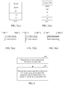
- FIG. 2(a) ⁇ FIG. 2(d) are schematic diagrams of a protocol architecture of the control plane and the user plane between the UE, the eNB and the core network (MME or SGW) in the LTE in the related art, as well as a protocol architecture of the control plane and the user plane between the eNB and the eNB, as shown in FIG. 2(a) ⁇ FIG. 2(d) ,
- the interfaces between the UE and the eNB from bottom to top can be divided into the following protocol layers: Physical (PHY) layer, Media Access Control (MAC) layer, and Radio Link Control (RLC) layer, Packet Data Convergence Protocol (PDCP) layer, and Radio Resource Control (RRC) layer.
- PHY Physical
- MAC Media Access Control
- RLC Radio Link Control
- PDCP Packet Data Convergence Protocol
- RRC Radio Resource Control
- the user plane protocol stacks of the interfaces between the UE and eNB from bottom to top are divided into the following protocol layers: PHY, MAC, RLC, and PDCP.
- the PHY layer is mainly set to transmit information to the MAC or higher layer via a transmission channel;
- the MAC layer is mainly set to provide the data transmission through a logical channel and be responsible for radio resource allocation and for achieving functions such as hybrid automatic repeat request (HARQ, Hybrid ARQ), Scheduling (SCH), priority processing and multiplexing/de-multiplexing (MUX);
- the RLC layer is mainly set to provide the user data and control data segmentation and retransmission services;
- the PDCP layer is mainly set to complete the user data transmission in the RRC or user plane;
- the RRC layer is mainly set to complete the broadcast, paging, radio resource control connection management, radio bearer control, mobility function, UE measurement report and control.
- the UE can only transmit and receive data with one eNodeB, which undoubtedly limits the user throughput and mobility performance of the UE.
- the protocol stack of S1-MME interface from bottom to top is divided into the following protocol layers: L1 protocol, L2 protocol, Internet protocol (IP), Stream Control Transmission Protocol (SCTP), and S1-Application Protocol (S1-AP).
- L1 protocol L2 protocol
- IP Internet protocol
- SCTP Stream Control Transmission Protocol
- S1-AP S1-Application Protocol
- the protocol stack of S1-U interface from bottom to top is divided into the following protocol layers: L1 protocol, L2 protocol, User Datagram Protocol/Internet Protocol (UDP/IP), GPRS Tunneling Protocol-User plane (GTP-U).
- L1 protocol L2 protocol
- UDP/IP User Datagram Protocol/Internet Protocol
- GTP-U GPRS Tunneling Protocol-User plane
- the protocol stack of X2-C interface from bottom to top is divided into the following protocol layers: L1 protocol, L2 protocol, IP, SCTP, X2-Application Protocol (X2-AP).
- the protocol stacks of X2-U interface from bottom to top are divided into the following protocol layers: L1 protocol, L2 protocol, UDP/IP, GTP-U.
- FIG. 3(a) ⁇ FIG. 3(c) are respectively schematic diagrams of existing S1 interface, X2 interface and enhanced radio access bearer (E-RAB) setup processes
- the S1 interface setup process generally comprises: the eNB sending a S1 SETUP REQUEST message to the MME, and the MME returning a S1 SETUP RESPONSE message to the eNB.
- the X2 interface setup process generally comprises: the eNB1 sending a X2 SETUP REQUEST message to the eNB2, and the eNB2 returning a X2 SETUP RESPONSE message to the eNB1.
- the radio access bearer setup process generally comprises: the MME sending an E-RAB SETUP REQUEST message to the eNB, and the eNB returning an E-RAB SETUP RESPONSE message to the MME.
- the coverage range of new cell is relatively small and does not share stations with the existing cells, and if a user moves between these new cells, or moves between the new cells and the existing cells, it will cause frequent switching process, making frequent user information transfer between the eNodeB, thus causing a great signaling impact on the core network, and further curbing the introduction of a large number of small cell eNodeBs at the radio side.
- the embodiment of the present invention provides a small cell eNodeB access system and a method for implementing network access therefor to increase user throughput and enhance mobility performance of a UE; at the same time, when the UE moves, it is able to avoid a signaling impact on the core network, thereby achieving the introduction of a large number of small cell eNodeBs at the radio side.
- the embodiment of the present invention discloses a small cell eNodeB access system, and the small cell eNodeB access system is provided with, a control plane gateway, which is connected to a radio access network and a core network, set to set up a control plane link between the core network and the radio access network;
- the control plane gateway works as an aggregation and distribution node of control plane signaling, aggregating signalings from different radio access network nodes and sending them to the core network, or distributing signalings from the core network to different radio access network nodes; and managing and coordinating one or more radio access network nodes;
- a user plane gateway which is connected to the radio access network and the core network, and set to set up a user plane link between the core network and the radio access network;
- the user plane gateway works as an aggregation and distribution node of user plane data, aggregating data from different radio access network nodes and sending them to the core network, or distributing data come from the core network to different radio access network nodes.
- connection link set up between the control plane gateway and the user plane gateway; the control plane gateway is further set to control and manage the user plane gateway via the set up connection link.
- Said controlling and managing the user plane gateway comprises: controlling the setup, deletion and modification of connections between the user plane gateway and the core network, as well as between the user plane gateway and the radio access network node.
- control plane gateways There are one or more control plane gateways; there are one or more user plane gateways.
- the system further comprises a mobility management entity (MME) connecting with the control plane gateway, a serving gateway (SGW) connecting with the user plane gateway and the MME, a macro eNodeB connecting with the control plane gateway and the user plane gateway respectively, and a small cell eNodeB respectively connecting with the control plane gateway and the user plane gateway.
- MME mobility management entity
- SGW serving gateway
- macro eNodeB connecting with the control plane gateway and the user plane gateway respectively
- small cell eNodeB respectively connecting with the control plane gateway and the user plane gateway.
- the user plane gateway and the control plane gateway are respectively independent physical nodes;
- the MME is set to connect to the control plane gateway via a S1-MME1 interface, connect to the SGW via a S11 interface; and also set to support managing the control plane link with the control plane gateway;
- the SGW is set to connect to the user plane gateway via the S1-U1 interface; and also set to support managing the S1-U1 interface connection with the user plane gateway;
- the control plane gateway is set to connect to the MME via a S1-MME1 interface, and connect to the macro eNodeB and/or the small cell eNodeB via a S1-MM2 interface, connect to the user plane gateway via the X-1 interface; further set to support functions of managing the control plane link with the MME and managing the control plane link with the eNodeB, and set to manage the S1-U1 interface connection set up between the user plane gateway and the SGW, as well as the S1-U2 interface connection set up between the user plane gateway and the
- the control plane gateway is further set to connect to other control plane gateways via a X-C interface, used for an inter-node negotiation when moving across the control plane gateways.
- the user plane gateway is further set to connect to other user plane eNodeBs via a X-U interface, used for transmitting data between nodes when moving across the user plane gateways.
- control plane gateway and the user plane gateway are co-located in the same physical entity, in this case, the X-1 interface between the control plane gateway and the user plane gateway is an internal interface.
- the control plane gateway and the user plane gateway are co-located and set in the macro eNodeB;
- the MME is set to connect to the macro eNodeB via the S1-MME1 interface, connect to the SGW via the S11 interface; further set to support managing the control plane link with the control plane gateway set in the macro eNodeB;
- the SGW is set to connect to the macro eNodeB via the S1-U1 interface; further set to support managing the S1-U1 connection with the user plane gateway set in the macro eNodeB;
- the macro eNodeB is set to connect to the MME via the S1-MME1 interface, and have the S1-U2 interface and the S1-MME2 interface between the small cell eNodeB and macro eNodeB; further set to support managing the control plane link with the small cell eNodeB, and support managing the S1-U2 connection with the small cell eNodeB;
- the small cell eNodeB is set to
- the control plane gateway and the user plane gateway are co-located and set in the macro eNodeB, and also one gateway is set between the macro eNodeB and the small cell eNodeB, and it is also responsible for managing the control plane and the user plane of the small cell eNodeB;
- the MME is set to connect to the macro eNodeB via the S1-MME1 interface, and connect to the SGW via the S11 interface; and further set to support managing the control plane link with the control plane gateway set in the macro eNodeB;
- the SGW is set to connect to the macro eNodeB via the S1-U1 interface; further set to support managing the S1-U1 connection with the user plane gateway set in the macro eNodeB;
- the macro eNodeB is set to connect to the MME via the S1-MME1 interface and set up the S1-U2 interface and S1-MME2 interface connections to the small cell eNodeB via a gateway; also set to support managing
- a X-3 interface connection is also set up via the gateway between the macro eNodeB and the small cell eNodeB.
- the control plane gateway is set in the macro eNodeB, and the user plane gateway is an independent entity;
- the MME is set to connect to the macro eNodeB via the S1-MME1 interface, and connect to the SGW via the S 11 interface;
- the SGW is set to connect to the user plane gateway via the S1-Ulinterface; also set to support managing the S1-U1 interface connection with the user plane gateway;
- the macro eNodeB is provided with a control plane gateway; set to connect to the MME via the S1-MME1 interface, connect to the small cell eNodeB via the S1-MM2 interface, wherein interfaces between the macro eNodeB and the user plane gateway comprise the X-1 interface and the S1-U2 interface; it is further set to support managing the S1-U2 interface connection with the user plane gateway, support managing the control plane link with
- the macro eNodeB and the small cell eNodeB are also connected via the X-3 interface.
- the user plane gateway is set in the SGW; the control plane gateway is set in the MME; the MME is provided with a control plane gateway; and it is set to connect to the SGW via the S11 interface and the X-1 interface, and respectively connect to the macro eNodeB and the small cell eNodeB via the S1-MME2 interface; also set to support managing two S1-MME2 interfaces for one user to respectively connect to different eNodeBs; the SGW is provided with a user plane gateway; and it is set to connect to the MME via the S11 interface and the X-1 interface, and respectively connect to the macro eNodeB and the small cell eNodeB via the S1-U2 interface; and further set to support managing two S1-U2 interfaces for one user to respectively connect to different eNodeBs.
- the embodiment of the present invention further provides a method for a small cell eNodeB access system implementing network access, and the small cell eNodeB access system is provided with, a control plane gateway, which connects to a radio access network and a core network, and is set to set up a control plane link between the core network and the radio access network; a user plane gateway, which connects to the radio access network and the core network, and is set to set up a user plane link between the core network and the radio access network; the method comprises:
- the method further comprises: setting up a connection link between the control plane gateway and the user plane gateway; through the set up connection link, the control plane gateway controlling and managing the user plane gateway.
- the control plane gateway controlling and managing the user plane gateway comprises:
- the method further comprises:
- the method further comprises:
- Said processing the control plane data of the access UE via the set up control plane link comprises:
- the aggregating or distributing comprises:
- the UE When the UE supports multiple streams, the UE stores the signaling connections between the control plane gateway and multiple radio access network nodes.
- a connection link is set up between the control plane gateway and the user plane gateway; the method further comprises: instructing the user plane gateway to manage the corresponding data connection.
- the mapping relationship is one-to-one mapping relationship; forwarding the signaling according to the mapping relationship; or, the mapping relationship is one-to-many relationship mapping, forwarding by proxy the signaling according to a specified rule.
- the method further comprises: migrating context configuration information related to the corresponding UE or an air interface connection.
- migrating context configuration information related to the corresponding UE or an air interface connection comprises:
- the aggregating or distributing comprises:
- the mapping relationship is a one-to-one mapping relationship; or the mapping relationship is a one-to-many mapping relationship, at this time, the user plane gateway maintains the one-to-many relationship in the context information of one UE: in the uplink direction, the user plane gateway aggregates multiple data channels into one data channel to transmit; in the downlink direction, the user plane gateway distributes data according to a preset rule.
- managing including setting up, deleting and modifying the data channel between the user plane gateways; and, maintaining the data channel mapping relationship between the access network nodes or the core network and the user plane gateway, forwarding data according to the mapping relationship, and supporting in managing the mapping relationship.
- the embodiment of the present invention provides, including respectively setting up the control plane link and the user plane link, the small cell eNodeB access system to process the control plane data of an access UE via the set up control plane link, and process the user plane data of the access UE via the set up user plane link.
- the UE have data transmission and reception with two different eNodeBs such as macro cell (eNodeB) and small cell (eNodeB) simultaneously by separating the control plane with the data plane, so as to increase the user throughput and enhance the mobility performance, and to solve the problem that the user switches between the cells so that information exchanges frequently between nodes and so as to cause an impact on the core network, and further to realize the introduction of a large number of small cell eNodeBs at the radio side.
- eNodeB macro cell
- eNodeB small cell
- FIG. 4 is a flow chart of a method for a small cell eNodeB access system achieving network access in accordance with an embodiment of the present invention, and as shown in FIG. 4 , it comprises the following steps:
- a control plane gateway is newly provided for connecting the radio access network and the core network, and a link set up via the control plane gateway between the core network and the radio access network is the control plane link.
- the control plane gateway works as an aggregation and distribution node of control plane signaling, aggregating signalings from different radio access network nodes and sending them to the core network, or distributing signalings from the core network to different radio access network nodes.
- the control plane gateway works as a management network element of radio access network node, coordinating and managing one or more radio access network nodes. Take the LTE network architecture for example, the control plane gateway connects to one or more MMEs via the S1-MME1 interface, and connects to one or more eNBs via the S1-MME2 interface.
- a user plane gateway is newly provided for connecting the radio access network and the core network, and a link set up via the user plane gateway between the core network and the wireless access network is the user plane link.
- the user plane gateway works as an aggregation and distribution node of user plane data, aggregating data from different radio access network nodes and sending them to the core network, or distributing data from the core network to different radio access network nodes.
- the user plane gateway connects to one or more SGWs via the S1-U1 interface and connects to one or more eNBs via the S1-U2 interface.
- the method according to the embodiment of the present invention further comprises: setting up the S11 interface which connects between the MME and the SGW and it is set to control and manage the SGW for the MME, and it is the interface in the related art; wherein, the S1-MME1 interface is connected between the control plane gateway and the MME, and it maybe an existing S1-MME interface.
- the S1-MME2 interface is connected between the control plane gateway and the eNodeB, and it can be an existing S1-MME interface, or it can be added with access network feedback information on its basis for a better distribution decision.
- the S1-U1 interface is connected between the user plane gateway and the SGW, and it is set to transmit data.
- it can be an existing S1-U interface and use the protocol stack IP/UDP/GTP-U.
- the S1-U2 interface is connected between the user plane gateway and the eNodeB, and it is set to transmit data.
- it can be similar to the existing S1-U interface and use the protocol stack IP/UDP/GTP-U.
- the method according to the embodiment of the present invention further comprises: a small cell eNodeB access system setting up a connection link between the control plane gateway and the user plane gateway.
- the control plane gateway implementing the control and management of the user plane gateway, specifically including: controlling a channel between the user plane gateway and the core network, as well as the set-up, deletion and modification of connections between the user plane gateway and the radio access network node.
- the modification comprises the modification of attributes and modification of forwarding relationships.
- the control plane gateway can control one or more user plane gateways, and the user plane gateway can be connected to one or more control plane gateways, which is conducive to the system expansion and load sharing.
- the method according to the embodiment of the present invention further comprises: a small cell eNodeB access system setting up a connection link between the user plane gateways, and via the connection link, it achieves transmitting data between nodes when the UE moves across the user plane gateways; meanwhile, the control plane gateway can also achieve the inter-node negotiation via that connection link when the UE moves across the control plane gateways.
- Step 401 the small cell eNodeB access system processes the control plane data of the access UE via the set up control plane link, and processes the user plane data of the access UE via the set up user plane link.
- the control plane gateway processes the control plane data, aggregates signalings from different radio access network nodes and sends them to the core network, or it distributes signalings from the core network to different radio access network nodes.
- eNodeB macro cell
- eNodeB small cell
- the signaling connections are managed according to the signalings of the core network or the radio access network nodes. Furthermore, when setting up a connection link between the control plane gateway and the user plane gateway, it further comprises instructing the user plane gateway via the X-1 interface to manage the corresponding data connection, that is, the management is performed through the user plane link of the user plane gateway.
- the signaling received from the core network or the radio access network nodes indicates that when it does not need to modify the connection between the control plane gateway or the user plane gateway and the core network, the signaling is terminated at the control plane gateway.
- mapping relationship When the mapping relationship is a one-to-one mapping relationship, the signaling is forwarded according to the mapping relationship; when the mapping relationship is a one-to-many relationship mapping, the signaling is forwarded by proxy according to the specified rule.
- the specified rule can be preset or configured.
- the specified rule can be a one-to-many mapping relationship of the core network and multiple radio access network nodes through the control plane gateway.
- control plane gateway When there is moving across the control plane gateways, between the control plane gateways, it further comprises migrating context configuration information related to the corresponding UE or air interface connection.
- the control plane gateway is a radio access network node for the core network, while it is a core network for the radio access network node.
- the user plane gateway processes the user plane data, and aggregates data from different radio access network nodes and sends them to the core network, or distributes data from the core network to different radio access network nodes. It specifically comprises: managing, including setting up, deleting, modifying the data channel between the core network and the user plane gateway as well as between the user plane gateway and the radio access network; maintaining the mapping relationship of data channels between the core network and the user plane gateway, as well as the user plane gateway and the radio access network nodes; forwarding data in accordance with the mapping relationship, and managing, including setting up, deleting, and modifying the mapping relationship.
- the mapping relationship can be a one-to-one mapping relationship, and it can also be a one-to-many mapping relationship.
- a one-to-many mapping relationship a plurality of data channels belong to one UE, and if the UE is connected with different eNodeBs, at this time, the user plane gateway maintains the one-to-many relationship in the context information of one UE: in the uplink direction, the user plane gateway aggregates a plurality of data channels into one data channel to transmit; in the downlink direction, the user plane gateway distributes data according to the preset rule such as the distribution algorithm, for example the data is distributed according to the load.
- a data channel between the user plane gateways is managed, including setting up, deleting and modifying, maintaining the data channel mapping relationship between the access network node and the user plane gateway, as well as the data channel mapping relationship between the core network and the user plane gateway, and the data is forwarded according to the mapping relationship, supporting in managing, including setting up, deleting and modifying, the mapping relationship.
- the user plane gateway is the radio access network node for the core network, and it is the core network for the radio access network node.
- the user plane gateway and the control plane gateway in the embodiment of the present invention are logical function nodes, and they can be deployed respectively into independent physical nodes or set in the original physical node according to the actual situation.
- the method for it achieving the network access will be described in detail.
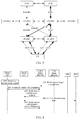
- FIG. 5 is a structural schematic diagram of the logic function of the first embodiment of the small cell eNodeB access system in accordance with an embodiment of the present invention, as shown in FIG. 5 , the UP-GW and the CP-GW are independent physical nodes respectively, and at this time, the functions of respective network nodes are as follows: the MME is connected to the control plane gateway via the S1-MME1 interface, and connected to the SGW via the S11 interface. In addition to existing functions of the MME in the LTE system Release 11, it is further set to support managing (including setting up, deleting and modifying) the control plane link with the control plane gateway.
- the SGW is connected to the user plane gateway via the S1-U1 interface.
- it is further set to support managing the S1-U1 interface connection with the user plane gateway, and the function is similar to the function of the GTP-U channel between the SGW and the eNodeB in the Release11, that is, the function of S1-U interface.
- the control plane gateway is connected to the MME via the S1-MME1 interface, connected to the macro eNodeB or the small cell eNodeB via the S1-MM2 interface, connected to the user plane gateway via the X-1 interface, connected to other control plane gateways via the X-C interface, and it is set for the inter-node negotiation when moving across the control plane gateways; and it is set to support the function of managing (including setting up, deleting and modifying) the control plane link with the MME, as well as managing the control plane link with the eNodeB; it is also set to manage related GTP-U channels, and the related GTP-U channels comprise the S1-U1 interface connection set up between the user plane gateway and the SGW, as well as the S1-U2 interface connection set up between the user plane gateway and the eNodeB; when a certain E-RAB of a certain UE moves between the small cell eNodeBs, the control plane gateway can make the E-RAB of UE move between the small
- the user plane gateway is connected to the SGW via the S1-U1 interface, connected to the macro eNodeB or the small cell eNodeB via the S1-U2 interface, connected to the control plane gateway via the X-1 interface, and connected to other user plane eNodeBs via the X-U interface, and it is set to transmit data between the nodes when moving across the user plane gateways.
- control plane gateway It is set to, under the control of the control plane gateway, support managing the S1-U1 interface connection with the SGW, as well as managing the S1-U2 interface with the eNodeB; when a certain E-RAB of a certain UE transfers between the small cell eNodeBs, the user plane gateway avoids the effect of the UE transferring between the small cell eNodeBs on the SGW through the method of remaining the GTP-U channel from the user plane gateway to the SGW; the user plane gateway is transparent to the macro cell.
- the macrocell is connected to the control plane gateway via the S1-MME2 interface, connected to the user plane gateway via the S1-U2 interface, connected to the UE via the Uu interface, and connected to the small cell eNodeB via the X-3 interface.
- the eNodeB of the LTE system Release 11 it is further set to support managing the control plane link with the control plane gateway, and managing the S1-U1 interface connection with the user plane gateway.
- the macro cell performs the mobility management.
- the small cell is connected to the user plane gateway via the S1-U2 interface, connected to the control plane gateway via the S1-MME2 interface, connected to the UE via the Uu interface, and connected to the macro eNodeB via the X-3 interface.
- DRB LTE system data radio bearer
- the protocol stack of Uu interface in the preferred embodiment of the present invention is the same as that in the related art; the protocol stacks and setup processes of the S1-MME1 interface and the S1-MME2 interface in the preferred embodiment of the present invention are the same as those of the S1-MME interface in the related art; the protocol stacks and the setup processes of the S1-U1 interface and the S1-U2 interface in the preferred embodiment of the present invention are the same as those of the S1-U interface in the related art; the protocol stack and the setup process of the X-1 interface in the preferred embodiment of the present invention are the same as those of the S1-C interface in the related art.
- processing the control plane data according to the control plane link comprises: in the uplink direction: a UE sending data to one or more eNodeBs via one or more radio interfaces, one or more eNodeBs sending data to the control plane gateway via the S1-MME2 interface, the control plane gateway sending data to the MME via the S1-MME1 interface, at this time the control plane gateway completing the aggregation of signalings from different radio access network nodes and sending them to the core network; in the downlink direction: the MME transmits data via the S1-MME1 interface to the control plane gateway, the control plane gateway sending data to one or more eNodeBs via the S1-MME2 interface, the eNodeB sending data to the UE via the radio interface, at this time, the control plane gateway distributing the signalings from the core network to different radio access network nodes.
- control plane link from the UE to the small cell eNodeB may exist or may not exist, and if not, the control plane data between the UE and the small cell eNodeB are forwarded via the macro eNodeB (ie, X-3 interface).
- Processing the user plane data according to the user plane link comprises: in the uplink direction: the UE sending data to one or more eNodeBs via one or more radio interfaces, one or more eNodeBs sending data to the user plane gateway via the S1-U2 interface, the user plane gateway sending data to the SGW via the S1-U1 interface, at this time, the user plane gateway working as the aggregation and distribution node of user plane data, aggregating data from different radio access network nodes and sending them to the core network; in the downlink direction: the SGW sending data to the user plane gateway via the S1-U1 interface, the user plane gateway sending data to one or more eNodeBs via the S1-U2 interface, the eNodeB sending data to the UE via the radio interface, at this time, the user plane gateway working as the aggregation and distribution node of user plane data, distributing data from the core network to different radio access network nodes.
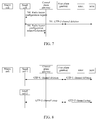
- FIG. 6 is a schematic diagram of the GTP-U channel setup process of the first embodiment of the small cell eNodeB access system in accordance with the embodiment of the present invention, at this time, the control plane gateway CP-GW is responsible for the GTP-U channel management, and as shown in FIG. 6 , assuming that the UE and the macro eNodeB have set up an air interface link, the macro eNodeB has configured the UE with a measurement task, and the UE has reported a measurement result to the macro eNodeB, comprising:
- FIG. 7 is a schematic diagram of the GTP-U channel deletion process of the first embodiment of the small cell eNodeB access system in accordance with an embodiment of the present invention, as shown in FIG. 7 , it comprises:
- FIG. 8 is a schematic diagram of the GTP-U channel replacement process of the first embodiment of the small cell eNodeB channel access system in accordance with the embodiment of the present invention, assuming that the UE moves from the small cell 1 to the small cell 2, as shown in FIG. 8 , it comprises:
- the management of GTP-U channel does not affect the core network, so that the introduction of a large number of small cells at the radio side becomes possible.
- FIG. 9 is a schematic diagram of the logic function structure of the second embodiment of the small cell eNodeB access system in accordance with an embodiment of the present invention, and as shown in FIG. 9 , in the logic function structure of the small cell eNodeB in the second embodiment, the implementation of various network nodes, compared to that in the first embodiment, the difference is that the control plane gateway and the user plane gateway are co-located in the same physical entity, and the X-1 interface between the two parties is an internal interface of the gateway, and the communication between the CP-GW and the UP-GW is implemented within the GW.
- its network access method is consistent to the one in the first embodiment and is not repeated here.
- the specific implementations of the GTP-U channel setup, deletion and replacement are consistent to those in the first embodiment and are not repeated here.
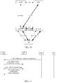
- FIG. 10 is a schematic diagram of the logic function structure of the third embodiment of the small cell eNodeB access system in accordance with the embodiment of the present invention, as shown in FIG. 10 , the control plane gateway and the user plane gateway are co-located and set in the macro eNodeB, in this case, the S1-MME1 interface is an interface between the MME and the M-eNB, the S1-U1 interface is an interface between the SGW and the M-eNB, and the S1-MME2 and S1-U2 are interfaces between the M-eNB and the S-eNB.
- the function of various network nodes are respectively:
- control plane gateway and the user plane gateway are consistent with those in the first embodiment shown in FIG. 5 , and the only difference is that, the interface between the control plane gateway and the user plane gateway is an internal interface.
- the macro cell is connected to the MME via the S1-MME1 interface, and it has the S1-U2 interface, the S1-MME2 interface and the X-3 interface with the small cell eNodeB, and it is connected to the UE via the Uu interface.
- the eNodeB In addition to having the functions of the eNodeB in the LTE system Release 11, it is further set to support managing the control plane link with the small eNodeB, similar to the function of managing the control plane link between the MME and the eNodeB in Release 11, namely the function of S1-MME interface; and to support managing the S1-U2 interface connection with the small eNodeB, similar to the function of the MME controlling the SGW to manage the related GTP-U channel in the Release11, that is, the function of S1-U interface.
- the macro eNodeB When a certain E-RAB of a certain UE transfers between the small cells, the macro eNodeB avoids the effect of such moving on the MME and the SGW through the method of remaining the control plane link between the macro eNodeB to the MME, as well as the GTP-U channel between the macro eNodeB and the SGW.
- the macro cell is further set to perform the access control and mobility management.
- the small cell has the S1-U2 interface, the S1-MME2 interface, and the X-3 interface with the macrocell eNodeB, and it is connected to the UE via the Uu interface.
- DRB data radio bearer
- the protocol stack of Uu interface in the preferred embodiment of the present invention is the same as that in the related art; the protocol stacks and setup processes of the S1-MME1 interface and the S1-MME2 interface in the preferred embodiment of the present invention are the same as those of the S1-MME interface in the related art; the protocol stacks and the setup processes of the S1-U1 interface and the S1-U2 interface in the preferred embodiment of the present invention are the same as those of the S1-U interface in the related art.
- processing the control plane data according to the control plane link comprises: in the uplink direction: a UE sending data to one or more eNodeBs via one or more radio interfaces, for the small eNodeBs, then sending data to the macro eNodeB via the S1-MME2 interface, the macro eNodeB sending data to the MME via the S1-MME1 interface; in the downlink direction: the MME sending data via the S1-MME1 interface to the macro eNodeB, the macro eNodeB sending data to the small eNodeB via the S1-MME2 interface or to the UE via the radio interface, and the small eNodeB sending data to the UE via the radio interface.
- control plane link between the UE and the small eNodeB may exist or may not exist, and if not, the control plane between the UE and the small eNodeB need to be forwarded via the macro eNodeB (ie, X-3 interface).
- Processing the user plane data according to the user plane link comprises: in the uplink direction: the UE sending data to one or more eNodeBs via one or more radio interfaces, the small eNodeB needing to send data to the macro eNodeB via the S1-U2 interface, the macro eNodeB sending data to the SGW via the S1-U1 interface; in the downlink direction: the SGW sending data to the macro eNodeB via the S1-U1 interface, the macro eNodeB sending data to the small cell via the S1-U2 interface or to the UE via the radio interface, the small eNodeB sending data to the UE via the radio interface.
- FIG. 11 is a schematic diagram of the GTP-U channel setup process of the third embodiment of the small cell eNodeB access system in accordance with an embodiment of the present invention, as shown in FIG. 11 , it comprises:
- FIG. 12 is a schematic diagram of the GTP-U channel deletion process of the third embodiment of the small cell eNodeB access system of the present invention, as shown in FIG. 12 , it comprises:
- FIG. 13 is a schematic diagram of the GTP-U channel replacement process of the third embodiment of the small cell eNodeB access system in accordance with the embodiment of the present invention, assuming that the UE moves from the small cell 1 to the small cell 2, as shown in FIG. 13 , it comprises:
- the management of GTP-U channel does not affect the core network, so that the introduction of a large number of small cells at the radio side becomes possible.
- FIG. 14 is a schematic diagram of the logic function structure of the fourth embodiment of the small cell eNodeB access system in accordance with the embodiment of the present invention, as shown in FIG. 14 , in the fourth embodiment, a gateway (GW2) is set between the macro eNodeB and the small cell eNodeB, and the GW2 is responsible for managing the control plane and the user plane of the small cell, compared with the structure of the third embodiment shown in FIG.
- GW2 gateway
- the difference is: the X-3 interface, the S1-MME2 interface (or the X-1 interface and the S1-MME2 interface together are called S1-MME2+ interface), as well as the S1-U2 interface is the interface between the GW2 and the small cell eNodeB and also the interface between the GW2 and the macro eNodeB.
- the functions of respective network nodes are respectively:
- the macro cell is connected to the MME via the S1-MME1 interface, and sets up the S1-U2 interface and S1-MME2 interface (further including the X-3 interface) connections to the small cell eNodeB via the gateway GW2, and it is connected to the UE via the Uu interface.
- the eNodeB in the LTE system Release11, it is further set to support the function of managing the control plane link with the gateway GW2.
- the macro cell is set to perform the access control and mobility management.
- the gateway GW2 supports the function of managing the control plane link and the user plane link with the eNodeB, similar to the function of managing the control plane link between the MME and the eNodeB in the Release 11, that is, the function of S1-MME interface, as well as the function of the SGW and the eNodeB managing the user plane link, that is, the function of S 1-U interface in the Release 11.
- the gateway GW2 can avoid the effect of such moving on the MME and the SGW through the method of remaining the control plane link and the user plane link to the macro eNodeB.
- the gateway is transparent to the macro cell.
- the small cell sets up the S1-U2 interface and S1-MME2 interface (further including the X-3 interface) connections with the macro cell via the gatway GW2, and it is connected to the UE via the Uu interface. It is set to support all the functions of supporting setting up the data radio bearer (DRB) of LTE system with the UE and communicating on the DRB, and it is also set to support managing the control plane link and the S1-U2 interface connections with the gateway.
- DRB data radio bearer
- the protocol stack of the Uu interface in the preferred embodiment of the present invention is the same as that in the related art; the protocol stacks and setup processes of the S1-MME1 interface and the S1-MME2 interface in the preferred embodiment of the present invention are the same as those of the S1-MME interface in the related art; the protocol stacks and the setup processes of the S1-U1 interface and the S1-U2 interface in the preferred embodiment of the present invention are the same as those of the S1-U interface in the related art.
- processing the control plane data according to the control plane link comprises: in the uplink direction: the UE sending data to one or more eNodeBs via one or more radio interfaces, the small eNodeB sending data to the GW2 via the S1-MME2 interface, the GW2 sending data to the macro eNodeB via the S1-MME2 interface and the macro eNodeB sending data to the MME via the S1-MME1 interface; in the downlink direction: the MME sending data via the S1-MME1 interface to the macro eNodeB, the macro eNodeB sending data to the GW2 via the S1-MME2 interface or sending data to the UE via the radio interface, GW2 sending data to the small eNodeB via the S1-MME2 interface and the small eNodeB sending data to the UE via the radio interface.
- the control plane link from the UE to the small eNodeB may exist or may not exist, and if
- Processing the user plane data according to the user plane link comprises: in the uplink direction: the UE sending data to one or more eNodeBs via one or more radio interfaces, for the small eNodeB, it also needing to send data to the GW2 via the S1-U2 interface, the GW2 then sending data to the macro eNodeB via the S1-U2 interface, and the macro eNodeB sending the data to the SGW via the S1-U1 interface; in the downlink direction: the SGW sending the data to the macro eNodeB via the S1-U1 interface, the macro eNodeB sending the data to the small eNodeB via the S1-U2 interface or to the UE via the radio interface directly, the small eNodeB sending data to the UE via the radio interface.
- FIG. 15 is a schematic diagram of the GTP-U channel setup process of the fourth embodiment of the small cell eNodeB access system in accordance with the embodiment of the present invention, in this embodiment, the gateway is the GW2 shown in FIG. 14 , and as shown in FIG. 15 , it comprises:
- FIG. 16 is a schematic diagram of the GTP-U channel deletion process of the fourth embodiment of the small cell eNodeB access system in accordance with the embodiment of the present invention, as shown in FIG. 16 , it comprises:
- FIG. 17 is a schematic diagram of the GTP-U channel replacement process of the fourth embodiment of the small cell eNodeB access system in accordance with the embodiment of the present invention, assuming that the UE moves from the small cell 1 to the small cell 2, as shown in FIG. 17 , it comprises:
- the GTP-U channel is composed of two GTP-U channels between the macro cell and the gateway, as well as between the gateway and the small cell 1.
- the management of GTP-U channel does not affect the core network, so that the introduction of a large number of small cells at the radio side becomes possible.
- FIG. 18 is a schematic diagram of the logic function structure of the fifth embodiment of the small cell eNodeB access system in accordance with the embodiment of the present invention, as shown in FIG. 18 , in the fifth embodiment, the control plane gateway is provided in the macro eNodeB, the user plane gateway is an independent entity, and the functions of respective network nodes are as follows:
- the SGW is connected to the user plane gateway via the S1-U1 interface.
- it is further set to support managing the S1-U1 interface connection with the user plane gateway.
- the macro cell is provided with the control plane gateway, and it is connected to the MME via the S1-MME1 interface, and connected to the small cell eNodeB via the S1-MM2 interface (further including the X-3 interface), and it has the X-1 interface and the S1-U2 interface with the user plane gateway, and it is connected to the UE via the Uu interface.
- the eNodeB In addition to having the functions of the eNodeB in the LTE system Release11, it is further set to support managing the S1-U2 interface connection with the user plane gateway, and support the function of managing the control plane link with the small cell eNodeB, similar to the function of managing the control plane link between the MME and the eNodeB in the Release 11, that is, the function of S1-MME interface ; in addition, it is further set to control the user plane gateway to manage the S1-U2 interface connection, similar to the function of the MME controlling the SGW to manage the related GTP-U channel, that is, the function of S1-U interface in the Release 11, wherein the related GTP-U channel comprises the S1-U1 interface connection between the user plane gateway and the SGW, as well as the S1-U2 interface connection between the user plane gateway and the eNodeB.
- the macro cell performs the access control and mobility management.
- the macro cell avoids the effect of such transfer on the MME through the method of remaining the control plane link from the control plane gateway to the MME.
- the user plane gateway is connected to the SGW via the S1-U1 interface, connected to the macro eNodeB via the S1-U2 interface and the X-1 interface, and connected to the small cell eNodeB via the S1-U2 interface, and it is set to support the function of managing the S1-U1 interface connection with the SGW, as well as managing the S1-U2 interface with the eNodeB, similar to the function of managing the GTP-U channel between the SGW and the eNodeB in the Release 11, that is, the function of S1-U interface, these management processes are controlled by the control plane gateway.
- the user plane gateway When a certain E-RAB of a certain UE transfers between the small cell eNodeBs, the user plane gateway avoids the effect of such movements on the SGW through the method of remaining the GTP-U channel from the user plane gateway to the SGW.
- the user plane gateway is transparent to the macro cell.
- the small cell is connected to the user plane gateway via the S1-U2 interface, connected to the macro eNodeB via the S1-MME2 interface (further including the X-3 interface), and connected to the UE via the Uu interface. It is set to support all the functions of setting up the data radio bearer (DRB) of LTE system with the UE and communicating on the DRB, and it is further set to support managing the control plane link with the control plane gateway, and managing the S1-U2 interface connection with the user plane gateway.
- DRB data radio bearer
- the protocol stack of the Uu interface in the preferred embodiment of the present invention is the same as that in the related art; the protocol stacks and the setup processes of the S1-MME1 interface and the S1-MME2 interface in the preferred embodiment of the present invention are the same as those of the S1-MME interface in the related art; the protocol stacks and the setup processes of the S1-U1 interface and the S1-U2 interface in the preferred embodiment of the present invention are the same as those of the S1-U interface in the related art; the protocol stack and the setup process of the X-1 interface in the preferred embodiment of the present invention are the same as those of the S1-C interface in the related art.
- processing the control plane data according to the control plane link comprises: in the uplink direction: the UE sending data to one or more eNodeBs via one or more radio interfaces, for the small enodeB, it also needing to send data to the macro eNodeB via the S1-MME2 interface, the macro eNodeB sending data to the MME via the S1-MME1 interface; in the downlink direction: the MME sending data to the macro eNodeB via the S1-MME1 interface, the macro eNodeB sending data to the small eNodeB via the S1-MME2 interface or to the UE directly via the radio interface and the small eNodeB sending data to UE via the radio interface.
- control plane link between the small eNodeB and the UE may exist or may not exist, and if not, the control plane between the UE and the small cell eNodeB needs to be forwarded via the macro eNodeB (ie, X-3 interface).
- macro eNodeB ie, X-3 interface
- Processing the user plane data according to the user plane link comprises: in the uplink direction: the UE sending data to one or more eNodeBs via one or more radio interfaces, one or more eNodeBs sending the data to the user plane gateway via the S1-U2 interface, and the user plane gateway sending the data to the SGW via the S1-U1 interface; in the downlink direction: the SGW sending the data to the user plane gateway via the S1-U1 interface, the user plane gateway sending the data to one or more eNodeBs via the S1-U2 interface, and the eNodeB sending the data to the UE via the radio interface.
- FIG. 19 is a schematic diagram of the GTP-U channel setup process of the fifth embodiment of the small cell eNodeB access system in accordance with the embodiment of the present invention, as shown in FIG. 19 , it comprises:
- FIG. 20 is a schematic diagram of the GTP-U channel deletion process of the fifth embodiment of the small cell eNodeB access system in accordance with the embodiment of the present invention, as shown in FIG. 20 , it comprises:
- FIG. 21 is a schematic diagram of the GTP-U channel replacement process of the fifth embodiment of the small cell eNodeB access system in accordance with the embodiment of the present invention, assuming that the UE moves from the small cell 1 to the small cell 2, as shown in FIG. 21 , it comprises:
- the management of GTP-U channel does not affect the core network, so that the introduction of a large number of small cells at the radio side becomes possible.
- FIG. 22 is a schematic diagram of the logic function structure of the sixth embodiment of the small cell eNodeB access system according to the embodiment of the present invention, in the present embodiment, the user plane gateway is set in the SGW and becomes SGW+, and the control plane gateway is set in the MME and becomes MME+, as shown in FIG. 22 , the difference from the structure of the first embodiment shown in FIG.
- the S1-MME1 interface becomes an internal interface of the MME network element
- the S1-U1 interface becomes an internal interface of the SGW network element
- the S1-MME2 interface becomes an interface between the MME and the macro eNodeB and between the MME and the small eNodeB
- the S1-U2 interface becomes an interface between the SGW and the macro eNodeB and between the SGW and the S-eNB
- the X-1 interface becomes one of the interfaces between the MME and the SGW.
- the functions of the macro cell and the small cell are consistent with those in the related art
- the functions of the other network nodes are respectively as follows:
- the SGW is provided with a user plane gateway. It is connected to the MME via the S11 interface and the X-1 interface, and respectively connected to the macro eNodeB and the small cell eNodeB via the S1-U2 interface. In addition to the existing function of the SGW in the LTE system Release11, it is further set to support managing two S1-U2 interfaces for one user to respectively connect to different eNodeBs.
- the UE has data transmission and reception with two different eNodeBs such as macro cell (eNodeB) and small cell (eNodeB) at the same time, thereby increasing the user throughput and enhancing the mobile performance, and solving the problem of frequent information exchange between nodes when the user switches between the cells so as to cause an impact on the core network, thus avoiding the signaling impact on the core network, and further achieving the introduction of a large number of small cell eNodeBs at the radio side.
- eNodeB macro cell
- eNodeB small cell
- the small cell eNodeB access system processes the control plane data of an access UE via the set up control plane link, and processes the user plane data of the access UE via the set up user plane link.
- the UE have data transmission and reception with two different eNodeBs such as macro cell (eNodeB) and small cell (eNodeB) simultaneously by separating the control plane with the data plane, so as to increase the user throughput and enhance the mobility performance, and to solve the problem that the user switches between the cells so that information exchanges frequently between nodes and so as to cause an impact on the core network, and further to realize the introduction of a large number of small cell eNodeBs at the radio side.
- eNodeB macro cell
- eNodeB small cell
Landscapes
- Engineering & Computer Science (AREA)
- Computer Networks & Wireless Communication (AREA)
- Signal Processing (AREA)
- Computer Security & Cryptography (AREA)
- Mobile Radio Communication Systems (AREA)
Applications Claiming Priority (2)
| Application Number | Priority Date | Filing Date | Title |
|---|---|---|---|
| CN201310198436.1A CN104185209B (zh) | 2013-05-24 | 2013-05-24 | 一种小蜂窝基站接入系统及其实现网络接入的方法 |
| PCT/CN2013/080035 WO2013185683A2 (fr) | 2013-05-24 | 2013-07-24 | Système d'accès à un noeud évolué b (enodeb) à petites cellules et procédé pour réaliser un accès réseau correspondant |
Publications (3)
| Publication Number | Publication Date |
|---|---|
| EP2991397A2 true EP2991397A2 (fr) | 2016-03-02 |
| EP2991397A4 EP2991397A4 (fr) | 2016-05-18 |
| EP2991397B1 EP2991397B1 (fr) | 2018-03-14 |
Family
ID=49758785
Family Applications (1)
| Application Number | Title | Priority Date | Filing Date |
|---|---|---|---|
| EP13804770.9A Active EP2991397B1 (fr) | 2013-05-24 | 2013-07-24 | Système d'accès à un noeud évolué b (enodeb) à petites cellules et procédé pour réaliser un accès réseau correspondant |
Country Status (5)
| Country | Link |
|---|---|
| US (1) | US9844000B2 (fr) |
| EP (1) | EP2991397B1 (fr) |
| JP (1) | JP6177428B2 (fr) |
| CN (1) | CN104185209B (fr) |
| WO (1) | WO2013185683A2 (fr) |
Cited By (2)
| Publication number | Priority date | Publication date | Assignee | Title |
|---|---|---|---|---|
| EP3032912A4 (fr) * | 2013-08-12 | 2016-09-07 | Zte Corp | Procédé de gestion de connexion et élément de réseau d'accès |
| EP3198988A4 (fr) * | 2014-09-26 | 2017-11-01 | Samsung Electronics Co., Ltd. | Procédé et appareil de prise en charge de technologie d'accès multi-radio |
Families Citing this family (31)
| Publication number | Priority date | Publication date | Assignee | Title |
|---|---|---|---|---|
| CN103945559B (zh) | 2013-01-18 | 2019-02-15 | 中兴通讯股份有限公司 | 网络接入系统及方法 |
| WO2015018038A1 (fr) | 2013-08-08 | 2015-02-12 | 华为技术有限公司 | Procédé et dispositif d'établissement de tunnels |
| US10362632B2 (en) * | 2014-06-12 | 2019-07-23 | Nokia Solutions And Networks Oy | Architecture for radio access network and evolved packet core |
| US10104582B2 (en) * | 2014-08-11 | 2018-10-16 | Cisco Technology, Inc. | Call preservation on handover |
| US10631287B2 (en) | 2014-09-26 | 2020-04-21 | Samsung Electronics Co., Ltd. | Method and apparatus for supporting multi-radio access technology |
| WO2016076564A1 (fr) * | 2014-11-12 | 2016-05-19 | Lg Electronics Inc. | Procédé et appareil de prise en charge d'un service de passerelle locale pour une connectivité double dans un système de communication sans fil |
| US10349313B2 (en) | 2015-03-02 | 2019-07-09 | Corning Optical Communications LLC | Enhanced features for a gateway coordinating multiple small cell radio access networks |
| US10728806B2 (en) | 2015-03-02 | 2020-07-28 | Corning Optical Communications LLC | Enhanced features for a gateway coordinating multiple small cell radio access networks |
| US10148510B2 (en) | 2015-03-02 | 2018-12-04 | Spidercloud Wireless, Inc. | Topology discovery and management and SON orchestration |
| US11071032B2 (en) | 2015-03-02 | 2021-07-20 | Corning Optical Communications LLC | Gateway coordinating multiple small cell radio access networks |
| JP6896640B2 (ja) * | 2015-03-04 | 2021-06-30 | アップル インコーポレイテッドApple Inc. | エッジクラウドモバイルプロキシに基づくミリ波無線アクセス技術の便宜的アクセス |
| US10129805B2 (en) | 2015-03-12 | 2018-11-13 | Spidercloud Wireless, Inc. | Hitless software upgrade for a virtualized gateway coordinating multiple small cell radio access networks |
| CN104869666B (zh) * | 2015-04-10 | 2019-05-21 | 电信科学技术研究院 | 数据无线承载配置方法、数据传输方法及设备 |
| WO2017045708A1 (fr) | 2015-09-16 | 2017-03-23 | Nokia Solutions And Networks Oy | Découplage de plan de commande et de plan d'utilisateur dans un réseau d'accès radioélectrique |
| WO2017045197A1 (fr) | 2015-09-18 | 2017-03-23 | 华为技术有限公司 | Procédé d'accès à un réseau local et dispositif associé |
| CN105228169A (zh) * | 2015-10-27 | 2016-01-06 | 京信通信技术(广州)有限公司 | 一种基站管理控制方法和装置 |
| EP3361681B1 (fr) * | 2015-10-30 | 2026-03-04 | Huawei Technologies Co., Ltd. | Procédé de configuration de passerelle et dispositif de passerelle |
| US11122505B2 (en) * | 2015-11-06 | 2021-09-14 | Apple Inc. | Downlink data handling for idle mode UE when the SGW is split into control plane node and user plane node |
| CN105491630A (zh) * | 2015-11-25 | 2016-04-13 | 广东欧珀移动通信有限公司 | 业务处理方法及装置 |
| CN106937342B (zh) * | 2015-12-31 | 2019-07-05 | 电信科学技术研究院 | 一种移动性管理方法和设备 |
| WO2017124231A1 (fr) * | 2016-01-18 | 2017-07-27 | 华为技术有限公司 | Procédé d'attribution d'adresse de protocole internet (ip), passerelle de plan de commande et passerelle de plan utilisateur |
| JP6650535B2 (ja) * | 2016-04-05 | 2020-02-19 | 華為技術有限公司Huawei Technologies Co.,Ltd. | モバイル協働型コミュニケーション方法及び装置 |
| WO2018035864A1 (fr) * | 2016-08-26 | 2018-03-01 | 华为技术有限公司 | Procédé et contrôleur de gestion de réseau |
| CN110546978B (zh) * | 2017-04-28 | 2023-12-05 | Oppo广东移动通信有限公司 | 获取上下文配置信息的方法、终端设备和接入网设备 |
| US11412554B2 (en) * | 2018-05-10 | 2022-08-09 | Apple Inc. | E1 interface setup in NG-RAN |
| CN111263466B (zh) * | 2018-12-03 | 2022-03-15 | 中泓慧联技术有限公司 | 一种支持用户面传输的系统和方法 |
| CN111263367B (zh) * | 2018-12-03 | 2023-05-09 | 中泓慧联技术有限公司 | 基于云端核心网epc的用户面传输系统和方法 |
| WO2020034585A1 (fr) * | 2019-01-18 | 2020-02-20 | Zte Corporation | Procédé et appareil d'élimination de connexions de plan d'utilisateur dans des systèmes à connectivité multiple |
| US12167483B2 (en) * | 2021-07-30 | 2024-12-10 | Cisco Technology, Inc. | Providing enhanced capacity for tenants in a neutral host network via multi-connectivity |
| CN112995936B (zh) * | 2021-03-12 | 2022-10-04 | 国网江苏省电力有限公司信息通信分公司 | 230MHz与1800MHz电力无线专网融合组网方法和系统 |
| CN119450591A (zh) * | 2023-08-04 | 2025-02-14 | 中兴通讯股份有限公司 | 通信方法、终端设备和网络设备 |
Family Cites Families (19)
| Publication number | Priority date | Publication date | Assignee | Title |
|---|---|---|---|---|
| EP1363468B1 (fr) | 2002-05-17 | 2004-10-27 | Alcatel | Reseau d'acces radio et element de reseau |
| CN100488284C (zh) * | 2006-01-26 | 2009-05-13 | 华为技术有限公司 | 一种3gpp演进网络中漫游用户数据路由优化方法 |
| CN102395202B (zh) * | 2006-04-28 | 2014-11-05 | 华为技术有限公司 | 一种演进网络中限制信令的实现方法 |
| JP5113684B2 (ja) * | 2008-09-05 | 2013-01-09 | 株式会社日立製作所 | アクセスゲートウェイ装置の制御方法及び通信システム |
| CN101686578B (zh) * | 2008-09-28 | 2012-05-23 | 中兴通讯股份有限公司 | 家庭演进基站系统及无线设备的接入方法 |
| JP5215900B2 (ja) | 2009-02-13 | 2013-06-19 | 株式会社日立製作所 | 移動無線通信システムおよびアクセスゲートウェイ |
| WO2010147605A1 (fr) * | 2009-06-19 | 2010-12-23 | Zte (Usa) Inc. | Techniques d'inter-réseautage pour transférer des paquets entre des passerelles de desserte source et cible |
| CN102348244B (zh) * | 2010-08-03 | 2014-11-05 | 华为技术有限公司 | 蜂窝通信系统、终端在小区间切换的方法及宏基站 |
| CN102075859A (zh) * | 2010-12-24 | 2011-05-25 | 大唐移动通信设备有限公司 | 一种基于lte系统的信息推送方法和系统 |
| CN102026405A (zh) * | 2010-12-29 | 2011-04-20 | 中兴通讯股份有限公司 | 连接处理方法及系统 |
| US20140011519A1 (en) * | 2011-04-03 | 2014-01-09 | Lg Electronics Inc. | Method for transmitting location information and user equipment |
| US9357584B2 (en) * | 2011-04-06 | 2016-05-31 | Nokia Solutions And Networks Oy | Dual in-band/out-band radio access system field |
| US20120327867A1 (en) * | 2011-06-27 | 2012-12-27 | Renesas Mobile Corporation | Subframe Scheduling |
| JP5885857B2 (ja) * | 2011-12-19 | 2016-03-16 | テレフオンアクチーボラゲット エル エム エリクソン(パブル) | ネットワークノード及びネットワークノードにおける方法 |
| WO2013123643A1 (fr) * | 2012-02-21 | 2013-08-29 | Nokia Siemens Networks Oy | Interfaces de signalisation dans les communications |
| WO2014113141A1 (fr) * | 2013-01-17 | 2014-07-24 | Intel IP Corporation | Techniques de déploiement de petites cellules en cellules secondaires pour équipement utilisateur |
| GB2512659A (en) * | 2013-04-05 | 2014-10-08 | Nec Corp | Communication system |
| CN104113881B (zh) * | 2013-04-16 | 2019-09-17 | 中兴通讯股份有限公司 | 一种无线资源管理方法、宏基站及低功率节点 |
| US9370020B2 (en) * | 2013-05-16 | 2016-06-14 | Alcatel Lucent | Methods and systems for scheduling communications in a co-channel network |
-
2013
- 2013-05-24 CN CN201310198436.1A patent/CN104185209B/zh active Active
- 2013-07-24 EP EP13804770.9A patent/EP2991397B1/fr active Active
- 2013-07-24 US US14/893,767 patent/US9844000B2/en active Active
- 2013-07-24 WO PCT/CN2013/080035 patent/WO2013185683A2/fr not_active Ceased
- 2013-07-24 JP JP2016514240A patent/JP6177428B2/ja active Active
Cited By (2)
| Publication number | Priority date | Publication date | Assignee | Title |
|---|---|---|---|---|
| EP3032912A4 (fr) * | 2013-08-12 | 2016-09-07 | Zte Corp | Procédé de gestion de connexion et élément de réseau d'accès |
| EP3198988A4 (fr) * | 2014-09-26 | 2017-11-01 | Samsung Electronics Co., Ltd. | Procédé et appareil de prise en charge de technologie d'accès multi-radio |
Also Published As
| Publication number | Publication date |
|---|---|
| US20160112945A1 (en) | 2016-04-21 |
| WO2013185683A2 (fr) | 2013-12-19 |
| CN104185209B (zh) | 2019-11-19 |
| EP2991397A4 (fr) | 2016-05-18 |
| CN104185209A (zh) | 2014-12-03 |
| JP2016522634A (ja) | 2016-07-28 |
| US9844000B2 (en) | 2017-12-12 |
| JP6177428B2 (ja) | 2017-08-09 |
| WO2013185683A3 (fr) | 2014-04-24 |
| EP2991397B1 (fr) | 2018-03-14 |
Similar Documents
| Publication | Publication Date | Title |
|---|---|---|
| US9844000B2 (en) | Small cell eNodeB access system and method for realizing network access therefor | |
| US8730918B2 (en) | Handover method based on mobile relay and mobile wireless relay system | |
| US9894695B2 (en) | Network access system and method | |
| JP6405454B2 (ja) | ユーザー装置の基地局ハンドオーバ方法及び基地局、ユーザー装置 | |
| CN101877860B (zh) | 中继节点、服务网关、中继数据的传输方法及系统 | |
| CN101932007B (zh) | 一种实现移动终端业务流传输的方法及无线中继系统 | |
| US20150146688A1 (en) | Radio communication system | |
| US20150327236A1 (en) | Data transmission method, base station, and user equipment | |
| EP3229552B1 (fr) | Procédé et appareil pour configurer une connexion tcp déconnectée dans un système de communication | |
| WO2011038690A1 (fr) | Procédé et dispositif pour le traitement de messages | |
| CN101938798A (zh) | 一种无线中继系统中终端的移动性管理方法及系统 | |
| TW201316815A (zh) | 基地台及其傳輸路徑建立方法 | |
| CN101998668A (zh) | 一种无线连接的gtp-u实体间传输数据的方法和装置 | |
| CN105144777A (zh) | 回程链路的承载分流方法及网络设备 | |
| WO2015085730A1 (fr) | Procédé, système et dispositif de connexion pour mettre en œuvre un service de passerelle locale | |
| WO2011020413A1 (fr) | Système de transmission et procédé de transmission employés pour un relais sans fil | |
| CN103582161B (zh) | 一种基于lte系统中继节点的数据传输方法 | |
| CN106162774B (zh) | 跨MeNB切换方法、装置及基站 | |
| CN105323852B (zh) | 上行承载的修改方法及装置 | |
| CN104378841A (zh) | 一种连接移动性管理方法及节点设备 | |
| CN106034363B (zh) | 一种数据转发方法及移动锚点 | |
| CN116506866A (zh) | 一种节点移动的机制和相应的节点 | |
| WO2022151298A1 (fr) | Procédé, appareil et système de migration de groupe | |
| CN102026293B (zh) | 一种核心网获知中继节点接入方式的系统及方法 | |
| Ghazali et al. | Handover signaling for 3 alternatives of Layer 3 Relay Node implementation in LTE-Advanced |
Legal Events
| Date | Code | Title | Description |
|---|---|---|---|
| PUAI | Public reference made under article 153(3) epc to a published international application that has entered the european phase |
Free format text: ORIGINAL CODE: 0009012 |
|
| 17P | Request for examination filed |
Effective date: 20151123 |
|
| AK | Designated contracting states |
Kind code of ref document: A2 Designated state(s): AL AT BE BG CH CY CZ DE DK EE ES FI FR GB GR HR HU IE IS IT LI LT LU LV MC MK MT NL NO PL PT RO RS SE SI SK SM TR |
|
| AX | Request for extension of the european patent |
Extension state: BA ME |
|
| RIC1 | Information provided on ipc code assigned before grant |
Ipc: H04W 84/04 20090101ALN20160405BHEP Ipc: H04W 28/02 20090101AFI20160405BHEP Ipc: H04W 92/20 20090101ALN20160405BHEP Ipc: H04W 28/08 20090101ALI20160405BHEP |
|
| A4 | Supplementary search report drawn up and despatched |
Effective date: 20160414 |
|
| DAX | Request for extension of the european patent (deleted) | ||
| RIC1 | Information provided on ipc code assigned before grant |
Ipc: H04W 16/32 20090101ALI20170706BHEP Ipc: H04W 28/08 20090101ALI20170706BHEP Ipc: H04W 28/02 20090101AFI20170706BHEP Ipc: H04W 76/02 20090101ALI20170706BHEP Ipc: H04W 92/20 20090101ALN20170706BHEP Ipc: H04W 88/16 20090101ALN20170706BHEP Ipc: H04W 48/20 20090101ALI20170706BHEP Ipc: H04W 84/04 20090101ALN20170706BHEP |
|
| GRAP | Despatch of communication of intention to grant a patent |
Free format text: ORIGINAL CODE: EPIDOSNIGR1 |
|
| STAA | Information on the status of an ep patent application or granted ep patent |
Free format text: STATUS: GRANT OF PATENT IS INTENDED |
|
| RIC1 | Information provided on ipc code assigned before grant |
Ipc: H04W 28/02 20090101AFI20170906BHEP Ipc: H04W 48/20 20090101ALI20170906BHEP Ipc: H04W 76/02 20090101ALI20170906BHEP Ipc: H04W 16/32 20090101ALI20170906BHEP Ipc: H04W 84/04 20090101ALN20170906BHEP Ipc: H04W 28/08 20090101ALI20170906BHEP Ipc: H04W 88/16 20090101ALN20170906BHEP Ipc: H04W 92/20 20090101ALN20170906BHEP |
|
| INTG | Intention to grant announced |
Effective date: 20170918 |
|
| GRAS | Grant fee paid |
Free format text: ORIGINAL CODE: EPIDOSNIGR3 |
|
| GRAA | (expected) grant |
Free format text: ORIGINAL CODE: 0009210 |
|
| STAA | Information on the status of an ep patent application or granted ep patent |
Free format text: STATUS: THE PATENT HAS BEEN GRANTED |
|
| AK | Designated contracting states |
Kind code of ref document: B1 Designated state(s): AL AT BE BG CH CY CZ DE DK EE ES FI FR GB GR HR HU IE IS IT LI LT LU LV MC MK MT NL NO PL PT RO RS SE SI SK SM TR |
|
| REG | Reference to a national code |
Ref country code: GB Ref legal event code: FG4D |
|
| REG | Reference to a national code |
Ref country code: CH Ref legal event code: EP Ref country code: AT Ref legal event code: REF Ref document number: 979973 Country of ref document: AT Kind code of ref document: T Effective date: 20180315 |
|
| REG | Reference to a national code |
Ref country code: IE Ref legal event code: FG4D |
|
| REG | Reference to a national code |
Ref country code: DE Ref legal event code: R096 Ref document number: 602013034467 Country of ref document: DE |
|
| REG | Reference to a national code |
Ref country code: SE Ref legal event code: TRGR |
|
| REG | Reference to a national code |
Ref country code: NL Ref legal event code: MP Effective date: 20180314 |
|
| REG | Reference to a national code |
Ref country code: LT Ref legal event code: MG4D |
|
| PG25 | Lapsed in a contracting state [announced via postgrant information from national office to epo] |
Ref country code: NO Free format text: LAPSE BECAUSE OF FAILURE TO SUBMIT A TRANSLATION OF THE DESCRIPTION OR TO PAY THE FEE WITHIN THE PRESCRIBED TIME-LIMIT Effective date: 20180614 Ref country code: CY Free format text: LAPSE BECAUSE OF FAILURE TO SUBMIT A TRANSLATION OF THE DESCRIPTION OR TO PAY THE FEE WITHIN THE PRESCRIBED TIME-LIMIT Effective date: 20180314 Ref country code: HR Free format text: LAPSE BECAUSE OF FAILURE TO SUBMIT A TRANSLATION OF THE DESCRIPTION OR TO PAY THE FEE WITHIN THE PRESCRIBED TIME-LIMIT Effective date: 20180314 Ref country code: LT Free format text: LAPSE BECAUSE OF FAILURE TO SUBMIT A TRANSLATION OF THE DESCRIPTION OR TO PAY THE FEE WITHIN THE PRESCRIBED TIME-LIMIT Effective date: 20180314 Ref country code: FI Free format text: LAPSE BECAUSE OF FAILURE TO SUBMIT A TRANSLATION OF THE DESCRIPTION OR TO PAY THE FEE WITHIN THE PRESCRIBED TIME-LIMIT Effective date: 20180314 |
|
| REG | Reference to a national code |
Ref country code: AT Ref legal event code: MK05 Ref document number: 979973 Country of ref document: AT Kind code of ref document: T Effective date: 20180314 |
|
| PG25 | Lapsed in a contracting state [announced via postgrant information from national office to epo] |
Ref country code: GR Free format text: LAPSE BECAUSE OF FAILURE TO SUBMIT A TRANSLATION OF THE DESCRIPTION OR TO PAY THE FEE WITHIN THE PRESCRIBED TIME-LIMIT Effective date: 20180615 Ref country code: LV Free format text: LAPSE BECAUSE OF FAILURE TO SUBMIT A TRANSLATION OF THE DESCRIPTION OR TO PAY THE FEE WITHIN THE PRESCRIBED TIME-LIMIT Effective date: 20180314 Ref country code: RS Free format text: LAPSE BECAUSE OF FAILURE TO SUBMIT A TRANSLATION OF THE DESCRIPTION OR TO PAY THE FEE WITHIN THE PRESCRIBED TIME-LIMIT Effective date: 20180314 Ref country code: BG Free format text: LAPSE BECAUSE OF FAILURE TO SUBMIT A TRANSLATION OF THE DESCRIPTION OR TO PAY THE FEE WITHIN THE PRESCRIBED TIME-LIMIT Effective date: 20180614 |
|
| PG25 | Lapsed in a contracting state [announced via postgrant information from national office to epo] |
Ref country code: NL Free format text: LAPSE BECAUSE OF FAILURE TO SUBMIT A TRANSLATION OF THE DESCRIPTION OR TO PAY THE FEE WITHIN THE PRESCRIBED TIME-LIMIT Effective date: 20180314 Ref country code: ES Free format text: LAPSE BECAUSE OF FAILURE TO SUBMIT A TRANSLATION OF THE DESCRIPTION OR TO PAY THE FEE WITHIN THE PRESCRIBED TIME-LIMIT Effective date: 20180314 Ref country code: AL Free format text: LAPSE BECAUSE OF FAILURE TO SUBMIT A TRANSLATION OF THE DESCRIPTION OR TO PAY THE FEE WITHIN THE PRESCRIBED TIME-LIMIT Effective date: 20180314 Ref country code: PL Free format text: LAPSE BECAUSE OF FAILURE TO SUBMIT A TRANSLATION OF THE DESCRIPTION OR TO PAY THE FEE WITHIN THE PRESCRIBED TIME-LIMIT Effective date: 20180314 Ref country code: IT Free format text: LAPSE BECAUSE OF FAILURE TO SUBMIT A TRANSLATION OF THE DESCRIPTION OR TO PAY THE FEE WITHIN THE PRESCRIBED TIME-LIMIT Effective date: 20180314 Ref country code: RO Free format text: LAPSE BECAUSE OF FAILURE TO SUBMIT A TRANSLATION OF THE DESCRIPTION OR TO PAY THE FEE WITHIN THE PRESCRIBED TIME-LIMIT Effective date: 20180314 Ref country code: EE Free format text: LAPSE BECAUSE OF FAILURE TO SUBMIT A TRANSLATION OF THE DESCRIPTION OR TO PAY THE FEE WITHIN THE PRESCRIBED TIME-LIMIT Effective date: 20180314 |
|
| PG25 | Lapsed in a contracting state [announced via postgrant information from national office to epo] |
Ref country code: CZ Free format text: LAPSE BECAUSE OF FAILURE TO SUBMIT A TRANSLATION OF THE DESCRIPTION OR TO PAY THE FEE WITHIN THE PRESCRIBED TIME-LIMIT Effective date: 20180314 Ref country code: SM Free format text: LAPSE BECAUSE OF FAILURE TO SUBMIT A TRANSLATION OF THE DESCRIPTION OR TO PAY THE FEE WITHIN THE PRESCRIBED TIME-LIMIT Effective date: 20180314 Ref country code: AT Free format text: LAPSE BECAUSE OF FAILURE TO SUBMIT A TRANSLATION OF THE DESCRIPTION OR TO PAY THE FEE WITHIN THE PRESCRIBED TIME-LIMIT Effective date: 20180314 Ref country code: SK Free format text: LAPSE BECAUSE OF FAILURE TO SUBMIT A TRANSLATION OF THE DESCRIPTION OR TO PAY THE FEE WITHIN THE PRESCRIBED TIME-LIMIT Effective date: 20180314 |
|
| REG | Reference to a national code |
Ref country code: DE Ref legal event code: R097 Ref document number: 602013034467 Country of ref document: DE |
|
| PG25 | Lapsed in a contracting state [announced via postgrant information from national office to epo] |
Ref country code: PT Free format text: LAPSE BECAUSE OF FAILURE TO SUBMIT A TRANSLATION OF THE DESCRIPTION OR TO PAY THE FEE WITHIN THE PRESCRIBED TIME-LIMIT Effective date: 20180716 |
|
| RIC2 | Information provided on ipc code assigned after grant |
Ipc: H04W 16/32 20090101ALI20170906BHEP Ipc: H04W 84/04 20090101ALN20170906BHEP Ipc: H04W 28/08 20090101ALI20170906BHEP Ipc: H04W 88/16 20090101ALN20170906BHEP Ipc: H04W 48/20 20090101ALI20170906BHEP Ipc: H04W 76/02 20181130ALI20170906BHEP Ipc: H04W 28/02 20090101AFI20170906BHEP Ipc: H04W 92/20 20090101ALN20170906BHEP |
|
| REG | Reference to a national code |
Ref country code: CH Ref legal event code: PK Free format text: BERICHTIGUNGEN |
|
| PLBE | No opposition filed within time limit |
Free format text: ORIGINAL CODE: 0009261 |
|
| STAA | Information on the status of an ep patent application or granted ep patent |
Free format text: STATUS: NO OPPOSITION FILED WITHIN TIME LIMIT |
|
| PG25 | Lapsed in a contracting state [announced via postgrant information from national office to epo] |
Ref country code: DK Free format text: LAPSE BECAUSE OF FAILURE TO SUBMIT A TRANSLATION OF THE DESCRIPTION OR TO PAY THE FEE WITHIN THE PRESCRIBED TIME-LIMIT Effective date: 20180314 |
|
| REG | Reference to a national code |
Ref country code: CH Ref legal event code: PK Free format text: BERICHTIGUNGEN |
|
| RIC2 | Information provided on ipc code assigned after grant |
Ipc: H04W 16/32 20090101ALI20170906BHEP Ipc: H04W 92/20 20090101ALN20170906BHEP Ipc: H04W 48/20 20090101ALI20170906BHEP Ipc: H04W 88/16 20090101ALN20170906BHEP Ipc: H04W 28/02 20090101AFI20170906BHEP Ipc: H04W 76/02 20090101ALI20170906BHEP Ipc: H04W 28/08 20090101ALI20170906BHEP Ipc: H04W 84/04 20090101ALN20170906BHEP |
|
| 26N | No opposition filed |
Effective date: 20181217 |
|
| PG25 | Lapsed in a contracting state [announced via postgrant information from national office to epo] |
Ref country code: SI Free format text: LAPSE BECAUSE OF FAILURE TO SUBMIT A TRANSLATION OF THE DESCRIPTION OR TO PAY THE FEE WITHIN THE PRESCRIBED TIME-LIMIT Effective date: 20180314 |
|
| REG | Reference to a national code |
Ref country code: CH Ref legal event code: PL |
|
| GBPC | Gb: european patent ceased through non-payment of renewal fee |
Effective date: 20180724 |
|
| PG25 | Lapsed in a contracting state [announced via postgrant information from national office to epo] |
Ref country code: LU Free format text: LAPSE BECAUSE OF NON-PAYMENT OF DUE FEES Effective date: 20180724 Ref country code: MC Free format text: LAPSE BECAUSE OF FAILURE TO SUBMIT A TRANSLATION OF THE DESCRIPTION OR TO PAY THE FEE WITHIN THE PRESCRIBED TIME-LIMIT Effective date: 20180314 |
|
| REG | Reference to a national code |
Ref country code: BE Ref legal event code: MM Effective date: 20180731 |
|
| REG | Reference to a national code |
Ref country code: IE Ref legal event code: MM4A |
|
| PG25 | Lapsed in a contracting state [announced via postgrant information from national office to epo] |
Ref country code: IE Free format text: LAPSE BECAUSE OF NON-PAYMENT OF DUE FEES Effective date: 20180724 Ref country code: GB Free format text: LAPSE BECAUSE OF NON-PAYMENT OF DUE FEES Effective date: 20180724 Ref country code: FR Free format text: LAPSE BECAUSE OF NON-PAYMENT OF DUE FEES Effective date: 20180731 Ref country code: LI Free format text: LAPSE BECAUSE OF NON-PAYMENT OF DUE FEES Effective date: 20180731 Ref country code: CH Free format text: LAPSE BECAUSE OF NON-PAYMENT OF DUE FEES Effective date: 20180731 |
|
| PG25 | Lapsed in a contracting state [announced via postgrant information from national office to epo] |
Ref country code: BE Free format text: LAPSE BECAUSE OF NON-PAYMENT OF DUE FEES Effective date: 20180731 |
|
| PG25 | Lapsed in a contracting state [announced via postgrant information from national office to epo] |
Ref country code: MT Free format text: LAPSE BECAUSE OF NON-PAYMENT OF DUE FEES Effective date: 20180724 |
|
| PG25 | Lapsed in a contracting state [announced via postgrant information from national office to epo] |
Ref country code: TR Free format text: LAPSE BECAUSE OF FAILURE TO SUBMIT A TRANSLATION OF THE DESCRIPTION OR TO PAY THE FEE WITHIN THE PRESCRIBED TIME-LIMIT Effective date: 20180314 |
|
| PG25 | Lapsed in a contracting state [announced via postgrant information from national office to epo] |
Ref country code: MK Free format text: LAPSE BECAUSE OF NON-PAYMENT OF DUE FEES Effective date: 20180314 Ref country code: HU Free format text: LAPSE BECAUSE OF FAILURE TO SUBMIT A TRANSLATION OF THE DESCRIPTION OR TO PAY THE FEE WITHIN THE PRESCRIBED TIME-LIMIT; INVALID AB INITIO Effective date: 20130724 |
|
| PG25 | Lapsed in a contracting state [announced via postgrant information from national office to epo] |
Ref country code: IS Free format text: LAPSE BECAUSE OF FAILURE TO SUBMIT A TRANSLATION OF THE DESCRIPTION OR TO PAY THE FEE WITHIN THE PRESCRIBED TIME-LIMIT Effective date: 20180714 |
|
| PGFP | Annual fee paid to national office [announced via postgrant information from national office to epo] |
Ref country code: SE Payment date: 20250610 Year of fee payment: 13 |
|
| PGFP | Annual fee paid to national office [announced via postgrant information from national office to epo] |
Ref country code: DE Payment date: 20250604 Year of fee payment: 13 |