EP2992159B1 - Windenergieanlage und windenergieanlagen- turm - Google Patents
Windenergieanlage und windenergieanlagen- turm Download PDFInfo
- Publication number
- EP2992159B1 EP2992159B1 EP14718034.3A EP14718034A EP2992159B1 EP 2992159 B1 EP2992159 B1 EP 2992159B1 EP 14718034 A EP14718034 A EP 14718034A EP 2992159 B1 EP2992159 B1 EP 2992159B1
- Authority
- EP
- European Patent Office
- Prior art keywords
- door
- wind turbine
- access door
- tower
- baffle plate
- Prior art date
- Legal status (The legal status is an assumption and is not a legal conclusion. Google has not performed a legal analysis and makes no representation as to the accuracy of the status listed.)
- Active
Links
Images


Classifications
-
- E—FIXED CONSTRUCTIONS
- E06—DOORS, WINDOWS, SHUTTERS, OR ROLLER BLINDS IN GENERAL; LADDERS
- E06B—FIXED OR MOVABLE CLOSURES FOR OPENINGS IN BUILDINGS, VEHICLES, FENCES OR LIKE ENCLOSURES IN GENERAL, e.g. DOORS, WINDOWS, BLINDS, GATES
- E06B1/00—Border constructions of openings in walls, floors, or ceilings; Frames to be rigidly mounted in such openings
- E06B1/56—Fastening frames to the border of openings or to similar contiguous frames
- E06B1/60—Fastening frames to the border of openings or to similar contiguous frames by mechanical means, e.g. anchoring means
- E06B1/6046—Clamping means acting perpendicular to the wall opening; Fastening frames by tightening or drawing them against a surface parallel to the opening
- E06B1/6061—Clamping means acting perpendicular to the wall opening; Fastening frames by tightening or drawing them against a surface parallel to the opening with separate clamping means acting on opposite wall or associated surfaces
-
- E—FIXED CONSTRUCTIONS
- E06—DOORS, WINDOWS, SHUTTERS, OR ROLLER BLINDS IN GENERAL; LADDERS
- E06B—FIXED OR MOVABLE CLOSURES FOR OPENINGS IN BUILDINGS, VEHICLES, FENCES OR LIKE ENCLOSURES IN GENERAL, e.g. DOORS, WINDOWS, BLINDS, GATES
- E06B5/00—Doors, windows, or like closures for special purposes; Border constructions therefor
- E06B5/10—Doors, windows, or like closures for special purposes; Border constructions therefor for protection against air-raid or other war-like action; for other protective purposes
- E06B5/11—Doors, windows, or like closures for special purposes; Border constructions therefor for protection against air-raid or other war-like action; for other protective purposes against burglary
- E06B5/113—Arrangements at the edges of the wings, e.g. with door guards to prevent the insertion of prying tools
-
- E—FIXED CONSTRUCTIONS
- E06—DOORS, WINDOWS, SHUTTERS, OR ROLLER BLINDS IN GENERAL; LADDERS
- E06B—FIXED OR MOVABLE CLOSURES FOR OPENINGS IN BUILDINGS, VEHICLES, FENCES OR LIKE ENCLOSURES IN GENERAL, e.g. DOORS, WINDOWS, BLINDS, GATES
- E06B1/00—Border constructions of openings in walls, floors, or ceilings; Frames to be rigidly mounted in such openings
- E06B1/56—Fastening frames to the border of openings or to similar contiguous frames
- E06B1/60—Fastening frames to the border of openings or to similar contiguous frames by mechanical means, e.g. anchoring means
- E06B1/6046—Clamping means acting perpendicular to the wall opening; Fastening frames by tightening or drawing them against a surface parallel to the opening
-
- E—FIXED CONSTRUCTIONS
- E06—DOORS, WINDOWS, SHUTTERS, OR ROLLER BLINDS IN GENERAL; LADDERS
- E06B—FIXED OR MOVABLE CLOSURES FOR OPENINGS IN BUILDINGS, VEHICLES, FENCES OR LIKE ENCLOSURES IN GENERAL, e.g. DOORS, WINDOWS, BLINDS, GATES
- E06B3/00—Window sashes, door leaves, or like elements for closing wall or like openings; Layout of fixed or moving closures, e.g. windows in wall or like openings; Features of rigidly-mounted outer frames relating to the mounting of wing frames
- E06B3/68—Window bars
- E06B3/685—False glazing bars
-
- E—FIXED CONSTRUCTIONS
- E06—DOORS, WINDOWS, SHUTTERS, OR ROLLER BLINDS IN GENERAL; LADDERS
- E06B—FIXED OR MOVABLE CLOSURES FOR OPENINGS IN BUILDINGS, VEHICLES, FENCES OR LIKE ENCLOSURES IN GENERAL, e.g. DOORS, WINDOWS, BLINDS, GATES
- E06B3/00—Window sashes, door leaves, or like elements for closing wall or like openings; Layout of fixed or moving closures, e.g. windows in wall or like openings; Features of rigidly-mounted outer frames relating to the mounting of wing frames
- E06B3/70—Door leaves
-
- F—MECHANICAL ENGINEERING; LIGHTING; HEATING; WEAPONS; BLASTING
- F03—MACHINES OR ENGINES FOR LIQUIDS; WIND, SPRING, OR WEIGHT MOTORS; PRODUCING MECHANICAL POWER OR A REACTIVE PROPULSIVE THRUST, NOT OTHERWISE PROVIDED FOR
- F03D—WIND MOTORS
- F03D13/00—Assembly, mounting or commissioning of wind motors; Arrangements specially adapted for transporting wind motor components
- F03D13/20—Arrangements for mounting or supporting wind motors; Masts or towers for wind motors
-
- F—MECHANICAL ENGINEERING; LIGHTING; HEATING; WEAPONS; BLASTING
- F03—MACHINES OR ENGINES FOR LIQUIDS; WIND, SPRING, OR WEIGHT MOTORS; PRODUCING MECHANICAL POWER OR A REACTIVE PROPULSIVE THRUST, NOT OTHERWISE PROVIDED FOR
- F03D—WIND MOTORS
- F03D80/00—Details, components or accessories not provided for in groups F03D1/00 - F03D17/00
-
- F—MECHANICAL ENGINEERING; LIGHTING; HEATING; WEAPONS; BLASTING
- F03—MACHINES OR ENGINES FOR LIQUIDS; WIND, SPRING, OR WEIGHT MOTORS; PRODUCING MECHANICAL POWER OR A REACTIVE PROPULSIVE THRUST, NOT OTHERWISE PROVIDED FOR
- F03D—WIND MOTORS
- F03D80/00—Details, components or accessories not provided for in groups F03D1/00 - F03D17/00
- F03D80/50—Maintenance or repair
-
- E—FIXED CONSTRUCTIONS
- E06—DOORS, WINDOWS, SHUTTERS, OR ROLLER BLINDS IN GENERAL; LADDERS
- E06B—FIXED OR MOVABLE CLOSURES FOR OPENINGS IN BUILDINGS, VEHICLES, FENCES OR LIKE ENCLOSURES IN GENERAL, e.g. DOORS, WINDOWS, BLINDS, GATES
- E06B3/00—Window sashes, door leaves, or like elements for closing wall or like openings; Layout of fixed or moving closures, e.g. windows in wall or like openings; Features of rigidly-mounted outer frames relating to the mounting of wing frames
- E06B3/70—Door leaves
- E06B2003/7049—Specific panel characteristics
- E06B2003/7051—Specific panel characteristics of layered construction involving different materials
-
- E—FIXED CONSTRUCTIONS
- E06—DOORS, WINDOWS, SHUTTERS, OR ROLLER BLINDS IN GENERAL; LADDERS
- E06B—FIXED OR MOVABLE CLOSURES FOR OPENINGS IN BUILDINGS, VEHICLES, FENCES OR LIKE ENCLOSURES IN GENERAL, e.g. DOORS, WINDOWS, BLINDS, GATES
- E06B3/00—Window sashes, door leaves, or like elements for closing wall or like openings; Layout of fixed or moving closures, e.g. windows in wall or like openings; Features of rigidly-mounted outer frames relating to the mounting of wing frames
- E06B3/04—Wing frames not characterised by the manner of movement
- E06B3/263—Frames with special provision for insulation
- E06B3/26301—Frames with special provision for insulation with prefabricated insulating strips between two metal section members
- E06B3/26303—Frames with special provision for insulation with prefabricated insulating strips between two metal section members with thin strips, e.g. defining a hollow space between the metal section members
-
- E—FIXED CONSTRUCTIONS
- E06—DOORS, WINDOWS, SHUTTERS, OR ROLLER BLINDS IN GENERAL; LADDERS
- E06B—FIXED OR MOVABLE CLOSURES FOR OPENINGS IN BUILDINGS, VEHICLES, FENCES OR LIKE ENCLOSURES IN GENERAL, e.g. DOORS, WINDOWS, BLINDS, GATES
- E06B5/00—Doors, windows, or like closures for special purposes; Border constructions therefor
- E06B5/10—Doors, windows, or like closures for special purposes; Border constructions therefor for protection against air-raid or other war-like action; for other protective purposes
- E06B5/11—Doors, windows, or like closures for special purposes; Border constructions therefor for protection against air-raid or other war-like action; for other protective purposes against burglary
-
- Y—GENERAL TAGGING OF NEW TECHNOLOGICAL DEVELOPMENTS; GENERAL TAGGING OF CROSS-SECTIONAL TECHNOLOGIES SPANNING OVER SEVERAL SECTIONS OF THE IPC; TECHNICAL SUBJECTS COVERED BY FORMER USPC CROSS-REFERENCE ART COLLECTIONS [XRACs] AND DIGESTS
- Y02—TECHNOLOGIES OR APPLICATIONS FOR MITIGATION OR ADAPTATION AGAINST CLIMATE CHANGE
- Y02E—REDUCTION OF GREENHOUSE GAS [GHG] EMISSIONS, RELATED TO ENERGY GENERATION, TRANSMISSION OR DISTRIBUTION
- Y02E10/00—Energy generation through renewable energy sources
- Y02E10/70—Wind energy
- Y02E10/72—Wind turbines with rotation axis in wind direction
-
- Y—GENERAL TAGGING OF NEW TECHNOLOGICAL DEVELOPMENTS; GENERAL TAGGING OF CROSS-SECTIONAL TECHNOLOGIES SPANNING OVER SEVERAL SECTIONS OF THE IPC; TECHNICAL SUBJECTS COVERED BY FORMER USPC CROSS-REFERENCE ART COLLECTIONS [XRACs] AND DIGESTS
- Y02—TECHNOLOGIES OR APPLICATIONS FOR MITIGATION OR ADAPTATION AGAINST CLIMATE CHANGE
- Y02E—REDUCTION OF GREENHOUSE GAS [GHG] EMISSIONS, RELATED TO ENERGY GENERATION, TRANSMISSION OR DISTRIBUTION
- Y02E10/00—Energy generation through renewable energy sources
- Y02E10/70—Wind energy
- Y02E10/728—Onshore wind turbines
Definitions
- the present invention relates to a wind turbine and a wind turbine tower.
- Wind turbines typically have a tower and access door at the bottom of the tower.
- the door is used to allow service and maintenance personnel to enter the wind turbine while unauthorized persons are prevented from entering.
- German Patent and Trademark Office has researched the following documents: DE 28 37 805 A1 ; DE 10 2007 016 756 A1 ; AT 006 967 U1 ; FR 2 588 606 A1 ; GB 2 185 056 A and EP 1 873 337 A2 ,
- a wind turbine with a tower is provided with an access door.
- the access door has a door lock and on its outer side a baffle plate, which extends over substantially the entire surface of the door and has a recess. In the region of the recess, a door knob is provided. An outer side of the baffle plate projects at least partially beyond the door lock to the outside.
- the access door has on its inside a grid consisting of vertical and horizontal struts.
- a distance between adjacent horizontal or between adjacent vertical struts is ⁇ 60 cm and in particular ⁇ 30 cm.
- a perforated plate is provided between the grid structure and the baffle plate.
- the access door is fastened to a tower wall via clamping plates.
- the invention also relates to a wind turbine tower with an access door, wherein the access door has a door lock and on its outside a baffle plate which extends substantially over the entire surface of the door and has a recess. In the region of the recess, a door knob is provided. An outer side of the baffle plate projects at least partially beyond the door lock to the outside.
- the access door meets at least DIN EN ISO 1627: 2011-09 and has resistance class 4.
- the invention relates to a concept to provide an access door for a wind turbine tower, which has a higher burglar resistance.
- a baffle plate may be provided on the outside of the door.
- the baffle plate has a recess in the region of the lock and the door knob.
- the door frame can be fixed by means of clamping plates on the tower wall.
- On the inside of the door horizontal and vertical braces are provided, which together form a grid structure.
- the distance between adjacent struts is preferably ⁇ 60 cm.
- the door frames may be provided outside.
- Such door frames are made of a hardened material.
- Fig. 1 shows a schematic representation of a wind turbine according to the invention according to the invention.
- the wind energy plant 100 has a tower 102 and a pod 104.
- a rotor 106 with three rotor blades 108 and a spinner 110 is provided at the nacelle 104.
- the rotor 106 is set in rotation by the wind during operation.
- a generator is directly or indirectly connected to the rotor, so that a rotational movement of the rotor leads to a rotational movement of the electric generator, which then generates an electric power.
- the pitch or the angle of attack of the rotor blades 108 can be changed by pitch motors on the rotor blade roots of the respective rotor blades.
- An access door 300 is provided in the lower area of the tower 102 of the wind turbine. This access door 300 is equipped according to the invention with an improved burglary protection.
- Fig. 2 shows a schematic view of an outside of an access door for a wind turbine according to a first embodiment.
- the access door 300 has a frame 305 and door hinges 301, by means of which the door can be opened.
- a bounce plate 310 is provided on the outside of the door.
- the baffle plate 310 has a recess 312 in the region of the door knob 307. This ensures that the area of the door knob 307 and the door lock with respect to the baffle plate 310 is reset. Thus, it can be prevented that a burglar can effectively use, for example, a crowbar or the like.
- Fig. 3 shows a schematic representation of an inside of an access door of a wind turbine according to the first embodiment.
- the access door has a frame 305 and vertical and horizontal struts 320, 321, 322.
- the vertical and horizontal struts 321, 322 form a lattice structure.
- the distance between adjacent horizontal and / or vertical struts is ⁇ 60 cm and in particular ⁇ 30 cm.
- a perforated plate 323 may be provided behind the grid structure 320, ie between the grid structure 320 and the baffle plate 310.
- the door has a door handle 308 on the inside.
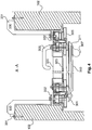
- Fig. 4 shows a sectional view taken along the section AA of Fig. 2
- the access door 300 is secured by means of clamping plates 330 on the wall 102 of the tower.
- the clamping plates 330 have a first end 331, which is fastened to the wall 102 of the tower, for example by means of screws, and a second end 332, which is fastened, for example by means of screws to a frame 305 of the door on.
- the door has on its outer side a baffle plate 310, which is designed bevelled at its ends 311.
- a grid structure 320 consisting of vertical and horizontal struts 321, 322 is provided. The struts can be welded together, for example.
- a door handle 308 and on the outside, a door knob 307 may be provided on the inside.
- the baffle plate 310 preferably protrudes at least partially beyond the door knob 307.
- the door knob 307 and a lock in the region of a recess 312 of the baffle plate 310 may be provided.
- the door 300 may be secured by door hinges 301 to a door frame 305.
- the baffle plate 310 may be screwed from the inside.
- holes may be provided in the door or above the door frame to provide passive ventilation of the tower interior.
- the distance between adjacent vertical or horizontal struts 321, 322 is ⁇ 30 cm.
- loosely mounted round material may be provided, which can prevent sawing through the bars.
- the perforated grid 323 serves as a burglary prevention.
Landscapes
- Engineering & Computer Science (AREA)
- Mechanical Engineering (AREA)
- Civil Engineering (AREA)
- Structural Engineering (AREA)
- Life Sciences & Earth Sciences (AREA)
- Sustainable Development (AREA)
- Sustainable Energy (AREA)
- Chemical & Material Sciences (AREA)
- Combustion & Propulsion (AREA)
- General Engineering & Computer Science (AREA)
- Wind Motors (AREA)
Description
- Die vorliegende Erfindung betrifft eine Windenergieanlage und einen Windenergieanlagen-Turm.
- Windenergieanlagen weisen typischerweise einen Turm und eine Zugangstür im unteren Bereich des Turmes auf. Die Tür dient dazu, dass Service- und Wartungspersonal die Windenergieanlage betreten kann während nicht-autorisierte Personen vom Zutritt abgehalten werden sollen.
- Daher ist es wichtig, dass die Zugangstür so ausgestaltet ist, dass nicht-autorisierte Personen keinen Zutritt zu der Windenergieanlage erhalten können. In letzter Zeit ist es vorgekommen, dass Diebe sich Zutritt zu Windenergieanlagen verschafft haben, um Metall zu klauen.
- In der prioritätsbegründenden deutschen Patentanmeldung hat das Deutsche Patent- und Markenamt die folgenden Dokumente recherchiert:
DE 28 37 805 A1 ;DE 10 2007 016 756 A1 ;AT 006 967 U1 FR 2 588 606 A1 GB 2 185 056 A EP 1 873 337 A2 . - Es ist daher eine Aufgabe der vorliegenden Erfindung, eine Windenergieanlage und einen Windenergieanlagen-Turm mit einer verbesserten Zugangstür vorzusehen.
- Diese Aufgabe wird durch eine Windenergieanlage nach Anspruch 1 und einen Windenergieanlagen-Turm nach Anspruch 6 gelöst.
- Somit wird eine Windenergieanlage mit einem Turm mit einer Zugangstür vorgesehen. Die Zugangstür weist ein Türschloss und an ihrer Außenseite ein Prellblech auf, welches sich im Wesentlichen über die gesamte Fläche der Tür erstreckt und eine Ausnehmung aufweist. Im Bereich der Ausnehmung ist ein Türknauf vorgesehen. Eine Außenseite des Prellblechs ragt zumindest teilweise über das Türschloss nach außen hinaus.
- Gemäß einem Aspekt der vorliegenden Erfindung weist die Zugangstür an ihrer Innenseite ein Gitter bestehend aus vertikalen und horizontalen Streben auf.
- Gemäß einem weiteren Aspekt der vorliegenden Erfindung ist ein Abstand zwischen benachbarten horizontalen oder zwischen benachbarten vertikalen Streben ≤60 cm und insbesondere ≤30 cm.
- Gemäß einem weiteren Aspekt der vorliegenden Erfindung ist ein Lochblech zwischen der Gitterstruktur und dem Prellblech vorgesehen.
- Gemäß einem weiteren Aspekt der vorliegenden Erfindung ist die Zugangstür über Klemmbleche an einer Turmwandung befestigt.
- Die Erfindung betrifft ebenfalls einen Windenergieanlagen-Turm mit einer Zugangstür, wobei die Zugangstür ein Türschloss und an ihrer Außenseite ein Prellblech aufweist, welches sich im Wesentlichen über die gesamte Fläche der Tür erstreckt und eine Ausnehmung aufweist. Im Bereich der Ausnehmung ist ein Türknauf vorgesehen. Eine Außenseite des Prellblechs ragt zumindest teilweise über das Türschloss nach außen hinaus.
- Gemäß der Erfindung erfüllt die Zugangstür mindestens DIN EN ISO 1627: 2011-09 und weist die Widerstandsklasse 4 auf.
- Die Erfindung betrifft einen Gedanken, eine Zugangstür für einen Windenergieanlagen-Turm vorzusehen, welcher über eine höhere Einbruchssicherheit verfügt. Dazu kann an der Außenseite der Tür eine Prellplatte vorgesehen sein. Die Prellplatte weist im Bereich des Schlosses und des Türknaufs eine Ausnehmung auf. Der Türrahmen kann mittels Klemmblechen an der Turmwandung befestigt werden. An der Innenseite der Tür sind horizontale und vertikale Verstrebungen vorgesehen, welche zusammen eine Gitterstruktur ausbilden. Der Abstand zwischen benachbarten Streben ist vorzugsweise ≤60 cm.
- Optional können die Türzargen außen vorgesehen sein. Derartige Türzargen bestehen aus einem gehärteten Material.
- Weitere Ausgestaltungen der Erfindung sind Gegenstand der Unteransprüche.
- Vorteile und Ausführungsbeispiele der Erfindung werden nachstehend unter Bezugnahme auf die Zeichnung näher erläutert.
- Fig. 1
- zeigt eine schematische Darstellung einer erfindungsgemäßen Windenergieanlage,
- Fig. 2
- zeigt eine schematische Darstellung einer Außenseite einer Zugangstür gemäß einem ersten Ausführungsbeispiel,
- Fig. 3
- zeigt eine schematische Darstellung einer Innenseite einer Zugangstür gemäß dem ersten Ausführungsbeispiel und
- Fig. 4
- zeigt eine Schnittansicht entlang des Schnitts A-A von
Fig. 2 . -
Fig. 1 zeigt eine schematische Darstellung einer erfindungsgemäßen Windenergieanlage gemäß der Erfindung. Die Windenergieanlage 100 weist einen Turm 102 und eine Gondel 104 auf. An der Gondel 104 ist ein Rotor 106 mit drei Rotorblättern 108 und einem Spinner 110 vorgesehen. Der Rotor 106 wird im Betrieb durch den Wind in eine Drehbewegung versetzt. Ein Generator ist direkt oder indirekt mit dem Rotor verbunden, so dass eine Drehbewegung des Rotors zu einer Drehbewegung des elektrischen Generators führt, der dann eine elektrische Leistung erzeugt. Der Pitch bzw. der Anstellwinkel der Rotorblätter 108 kann durch Pitchmotoren an den Rotorblattwurzeln der jeweiligen Rotorblätter verändert werden. Im unteren Bereich des Turms 102 der Windenergieanlage ist eine Zugangstür 300 vorgesehen. Diese Zugangstür 300 ist erfindungsgemäß mit einem verbesserten Einbruchsschutz ausgestattet. -
Fig. 2 zeigt eine schematische Ansicht einer Außenseite einer Zugangstür für eine Windenergieanlage gemäß einem ersten Ausführungsbeispiel. Die Zugangstür 300 weist eine Zarge 305 und Türbänder 301 auf, mittels welcher die Tür geöffnet werden kann. An der Außenseite der Tür ist eine Prellplatte 310 vorgesehen. Die Prellplatte 310 weist im Bereich des Türknaufs 307 eine Ausnehmung 312 auf. Damit wird erreicht, dass der Bereich des Türknaufs 307 und des Türschlosses gegenüber der Prellplatte 310 zurückgesetzt ist. Somit kann verhindert werden, dass ein Einbrecher z.B. ein Brecheisen oder dergleichen wirkungsvoll einsetzen kann. -
Fig. 3 zeigt eine schematische Darstellung einer Innenseite einer Zugangstür einer Windenergieanlage gemäß dem ersten Ausführungsbeispiel. Die Zugangstür weist eine Zarge 305 sowie vertikale und horizontale Streben 320, 321, 322 auf. Die vertikalen und horizontalen Streben 321, 322 bilden eine Gitterstruktur. Der Abstand zwischen benachbarten horizontalen und/oder vertikalen Streben ist ≤60 cm und insbesondere ≤30 cm. Optional kann ein Lochblech 323 hinter der Gitterstruktur 320 d.h. zwischen der Gitterstruktur 320 und der Prellplatte 310 vorgesehen sein. Die Tür weist an der Innenseite einen Türgriff 308 auf. - Durch die Gitterstruktur 320 an der Innenseite der Zugangstür 300 kann sichergestellt werden, dass selbst wenn die Prellplatte 310 entfernt worden ist, ein Zugang in die Windenergieanlage effektiv verhindert werden kann.
-
Fig. 4 zeigt eine Schnittansicht entlang des Schnitts A-A vonFig. 2 . Die Zugangstür 300 ist mittels Klemmblechen 330 an der Wandung 102 des Turmes befestigt. Die Klemmbleche 330 weisen ein erstes Ende 331, das an der Wandung 102 des Turmes z.B. mittels Schrauben befestigt wird, und ein zweites Ende 332, das z.B. mittels Schrauben an einer Zarge 305 der Tür befestigt wird, auf. Die Tür weist an ihrer Außenseite eine Prellplatte 310 auf, welche an ihren Enden 311 abgeschrägt ausgestaltet ist. An der Innenseite der Tür ist eine Gitterstruktur 320 bestehend aus vertikalen und horizontalen Streben 321, 322 vorgesehen. Die Streben können z.B. miteinander verschweißt werden. - An der Innenseite kann ein Türgriff 308 und an der Außenseite kann ein Türknauf 307 vorgesehen sein. Die Prellplatte 310 ragt vorzugsweise zumindest teilweise über den Türknauf 307 hinaus. Der Türknauf 307 sowie ein Schloss im Bereich einer Ausnehmung 312 der Prellplatte 310 vorgesehen sein.
- Die Tür 300 kann mittels Türbändern 301 an einer Türzarge 305 befestigt sein.
- Gemäß der Erfindung kann die Prellplatte 310 von innen verschraubt sein.
- Optional können in der Tür oder oberhalb des Türrahmens Löcher vorgesehen sein, um eine passive Belüftung des Turminneren vorzusehen.
- Vorzugsweise ist der Abstand zwischen benachbarten vertikalen oder horizontalen Streben 321, 322 ≤30 cm.
- Optional kann in den vertikalen und/oder horizontalen Streben 321, 322 lose gelagertes Rundmaterial vorgesehen sein, was ein Durchsägen der Gitterstäbe verhindern kann.
- Das Lochgitter 323 dient als Einbruchshinderung.
Claims (4)
- Windenergieanlage, mit
einem Turm (102), der eine Zugangstür (300) aufweist,
dadurch gekennzeichnet, dass die Zugangstür (300) ein Türschloss und an einer Außenseite ein Prellblech (310) aufweist, welches sich im Wesentlichen über die gesamte Fläche der Zugangstür (300) erstreckt und eine Ausnehmung (312) aufweist,
wobei im Bereich der Ausnehmung (312) ein Türknauf (307) vorgesehen ist,
wobei eine Außenseite des Prellblechs (310) zumindest teilweise über das Türschloss nach außen hinausragt,
wobei die Zugangstür (300) an einer Innenseite ein Gitter bestehend aus vertikalen und horizontalen Streben (321, 322; 320) aufweist. - Windenergieanlage nach Anspruch 1, wobei
ein Abstand zwischen benachbarten horizontalen Streben (322) oder zwischen benachbarten vertikalen Streben (321) ≤ 60 cm und insbesondere ≤ 30 cm ist. - Windenergieanlage nach einem der Ansprüche 1 oder 2, wobei
ein Lochblech (323) zwischen der Gitterstruktur (320) und dem Prellblech (310) vorgesehen ist. - Windenergieanlage nach einem der Ansprüche 1 bis 3, wobei
die Zugangstür (300) über Klemmbleche (330) an einer Turmwandung befestigt ist.
Applications Claiming Priority (2)
| Application Number | Priority Date | Filing Date | Title |
|---|---|---|---|
| DE102013207908.7A DE102013207908A1 (de) | 2013-04-30 | 2013-04-30 | Windenergieanlage und Windenergieanlagen-Turm |
| PCT/EP2014/057303 WO2014177357A1 (de) | 2013-04-30 | 2014-04-10 | Windenergieanlage und windenergieanlagen-turm |
Publications (2)
| Publication Number | Publication Date |
|---|---|
| EP2992159A1 EP2992159A1 (de) | 2016-03-09 |
| EP2992159B1 true EP2992159B1 (de) | 2019-12-04 |
Family
ID=50513227
Family Applications (1)
| Application Number | Title | Priority Date | Filing Date |
|---|---|---|---|
| EP14718034.3A Active EP2992159B1 (de) | 2013-04-30 | 2014-04-10 | Windenergieanlage und windenergieanlagen- turm |
Country Status (19)
| Country | Link |
|---|---|
| US (1) | US20160102493A1 (de) |
| EP (1) | EP2992159B1 (de) |
| JP (1) | JP2016516943A (de) |
| KR (1) | KR20160008207A (de) |
| CN (1) | CN105164359A (de) |
| AR (1) | AR096116A1 (de) |
| AU (1) | AU2014261693A1 (de) |
| BR (1) | BR112015027359A2 (de) |
| CA (1) | CA2907747C (de) |
| CL (1) | CL2015003166A1 (de) |
| DE (1) | DE102013207908A1 (de) |
| DK (1) | DK2992159T3 (de) |
| ES (1) | ES2773137T3 (de) |
| MX (1) | MX2015014205A (de) |
| NZ (1) | NZ712514A (de) |
| PT (1) | PT2992159T (de) |
| RU (1) | RU2627011C2 (de) |
| TW (1) | TW201508169A (de) |
| WO (1) | WO2014177357A1 (de) |
Families Citing this family (8)
| Publication number | Priority date | Publication date | Assignee | Title |
|---|---|---|---|---|
| DK178586B1 (en) | 2015-02-02 | 2016-07-25 | Vestas Wind Sys As | Wind turbine access panel and method for securing same |
| DK178587B1 (en) * | 2015-02-02 | 2016-07-25 | Vestas Wind Sys As | Access panel for a wind turbine tower and method for securing same |
| DE202015102525U1 (de) | 2015-05-18 | 2016-08-22 | Nordex Energy Gmbh | Zugangstür für technische Betriebsräume |
| DE102015212321A1 (de) * | 2015-07-01 | 2017-01-05 | Wobben Properties Gmbh | Windenergieanlage und Kühlvorrichtung für eine Windenergieanlage |
| DE102015122855A1 (de) * | 2015-12-28 | 2017-06-29 | Wobben Properties Gmbh | Windenergieanlage und Kühlvorrichtung für eine Windenergieanlage |
| JP6650318B2 (ja) * | 2016-03-29 | 2020-02-19 | 株式会社日立製作所 | 風力発電装置 |
| EP3828409B1 (de) * | 2019-11-27 | 2023-10-25 | Siemens Gamesa Renewable Energy A/S | Lukenanordnung zum verschliessen einer öffnung im boden einer windturbine und windturbine |
| EP4212723B1 (de) * | 2022-01-14 | 2025-03-12 | Siemens Gamesa Renewable Energy A/S | Sicherheitstüranordnung |
Family Cites Families (27)
| Publication number | Priority date | Publication date | Assignee | Title |
|---|---|---|---|---|
| US4175357A (en) * | 1973-12-10 | 1979-11-27 | Goldhaber Marvin L | Protective enclosure for building openings |
| US3894357A (en) * | 1974-03-28 | 1975-07-15 | California Crime Technological | Security door |
| DE2837805A1 (de) * | 1978-08-30 | 1980-03-13 | Bochumer Eisen Heintzmann | Tuer- oder fensterartiges verschlusselement |
| US4389817A (en) * | 1981-06-01 | 1983-06-28 | Olberding Leonard E | Double door assembly |
| ATE24570T1 (de) * | 1982-11-15 | 1987-01-15 | Benedetto Fedeli | Verriegelungssystem fuer tueren, fenster und dergleichen mit automatisch vom tuerrahmen in den fluegel gleitenden blockierungsgliedern. |
| BE899889A (fr) * | 1984-06-12 | 1984-10-01 | V A Q Vente D Articles De Quin | Perfectionnement aux blindage des portes. |
| FR2588606B1 (fr) * | 1985-10-10 | 1988-05-27 | Picard | Grille anti-effraction pour porte. |
| GB2185056B (en) * | 1986-01-07 | 1989-10-25 | Martin Roberts Limited | Security panel for a new or existing door |
| US4763499A (en) * | 1987-04-07 | 1988-08-16 | Boyle John J | Door security system |
| US4912877A (en) * | 1988-02-19 | 1990-04-03 | Strydom Nicolaas J H | Security door |
| US5581948A (en) * | 1995-08-11 | 1996-12-10 | Simonsen; Eric A. | Kick resistant door assembly |
| AUPP506898A0 (en) * | 1998-08-05 | 1998-08-27 | Strategic Manufacturing Pty Ltd | Security door |
| ITMI20011540A1 (it) * | 2001-07-19 | 2003-01-19 | Bebstone S R L | Struttura di porta in materiale lapideo |
| US20040003559A1 (en) * | 2002-04-24 | 2004-01-08 | Minke Ronald C. | Doors and methods of producing same |
| US20030200714A1 (en) * | 2002-04-24 | 2003-10-30 | Minke Ronald C. | High performance door |
| GB2401899A (en) * | 2003-05-20 | 2004-11-24 | Paul Clancy | Security door |
| AT6967U1 (de) * | 2003-05-22 | 2004-06-25 | Guttmann Herbert | Sektionaltor |
| DE102006029822B4 (de) * | 2006-06-28 | 2008-06-12 | Klaus Imhof | Vorrichtung zum Sichern von Baustellentüren gegen unrechtmäßiges Eindringen in Gebäude |
| DE102007016756A1 (de) * | 2007-04-07 | 2008-10-09 | Reinhold Gernandt | Windkraftanlage mit horizontal liegender Welle und drehendem Turm zur Kraftübertragung |
| CN201321804Y (zh) * | 2008-12-26 | 2009-10-07 | 南京泰通科技有限公司 | 一种多功能智能型防盗门 |
| US8176682B2 (en) * | 2009-09-14 | 2012-05-15 | Gaven Industries, Inc. | Double panel door and double frame providing radio frequency shielding and soundproofing |
| CA2699704A1 (en) * | 2010-04-12 | 2011-10-12 | Jorge Torres | Door frame security pieces and system |
| CN201786578U (zh) * | 2010-08-11 | 2011-04-06 | 上海泰胜(东台)电力工程机械有限公司 | 风电塔筒舱门 |
| US8171674B2 (en) * | 2010-12-16 | 2012-05-08 | General Electric Company | Doorway for a wind turbine tower |
| RU106309U1 (ru) * | 2011-02-15 | 2011-07-10 | Государственное образовательное учреждение высшего профессионального образования "Пензенская государственная технологическая академия" | Гибридная альтернативная энергетическая установка |
| CN202300056U (zh) * | 2011-10-19 | 2012-07-04 | 邓德万 | 具有圆弧形防撬结构的防盗门 |
| CN103510816B (zh) * | 2013-10-11 | 2015-08-26 | 宜兴市万向防火门有限公司 | 一种核电门 |
-
2013
- 2013-04-30 DE DE102013207908.7A patent/DE102013207908A1/de not_active Withdrawn
-
2014
- 2014-04-10 CA CA2907747A patent/CA2907747C/en not_active Expired - Fee Related
- 2014-04-10 NZ NZ712514A patent/NZ712514A/en not_active IP Right Cessation
- 2014-04-10 RU RU2015150962A patent/RU2627011C2/ru active
- 2014-04-10 JP JP2016510979A patent/JP2016516943A/ja active Pending
- 2014-04-10 CN CN201480024308.8A patent/CN105164359A/zh active Pending
- 2014-04-10 KR KR1020157033722A patent/KR20160008207A/ko not_active Ceased
- 2014-04-10 MX MX2015014205A patent/MX2015014205A/es unknown
- 2014-04-10 AU AU2014261693A patent/AU2014261693A1/en not_active Abandoned
- 2014-04-10 ES ES14718034T patent/ES2773137T3/es active Active
- 2014-04-10 US US14/888,073 patent/US20160102493A1/en not_active Abandoned
- 2014-04-10 DK DK14718034.3T patent/DK2992159T3/da active
- 2014-04-10 PT PT147180343T patent/PT2992159T/pt unknown
- 2014-04-10 WO PCT/EP2014/057303 patent/WO2014177357A1/de not_active Ceased
- 2014-04-10 BR BR112015027359A patent/BR112015027359A2/pt not_active Application Discontinuation
- 2014-04-10 EP EP14718034.3A patent/EP2992159B1/de active Active
- 2014-04-25 TW TW103115065A patent/TW201508169A/zh unknown
- 2014-04-28 AR ARP140101741A patent/AR096116A1/es active IP Right Grant
-
2015
- 2015-10-28 CL CL2015003166A patent/CL2015003166A1/es unknown
Non-Patent Citations (1)
| Title |
|---|
| None * |
Also Published As
| Publication number | Publication date |
|---|---|
| RU2627011C2 (ru) | 2017-08-02 |
| CL2015003166A1 (es) | 2016-04-22 |
| CA2907747A1 (en) | 2014-11-06 |
| CN105164359A (zh) | 2015-12-16 |
| PT2992159T (pt) | 2020-02-24 |
| TW201508169A (zh) | 2015-03-01 |
| CA2907747C (en) | 2017-09-12 |
| KR20160008207A (ko) | 2016-01-21 |
| WO2014177357A1 (de) | 2014-11-06 |
| JP2016516943A (ja) | 2016-06-09 |
| NZ712514A (en) | 2016-08-26 |
| AU2014261693A1 (en) | 2015-10-15 |
| US20160102493A1 (en) | 2016-04-14 |
| DK2992159T3 (da) | 2020-03-09 |
| DE102013207908A1 (de) | 2014-10-30 |
| RU2015150962A (ru) | 2017-06-05 |
| ES2773137T3 (es) | 2020-07-09 |
| BR112015027359A2 (pt) | 2017-09-12 |
| AR096116A1 (es) | 2015-12-09 |
| EP2992159A1 (de) | 2016-03-09 |
| MX2015014205A (es) | 2015-12-11 |
Similar Documents
| Publication | Publication Date | Title |
|---|---|---|
| EP2992159B1 (de) | Windenergieanlage und windenergieanlagen- turm | |
| EP2273101B1 (de) | Verfahren zur montage von rotorblättern einer windenergieanlage | |
| EP2807107B1 (de) | Verfahren und vorrichtung zum montieren einer rotornabe einer windenergieanlage | |
| EP3011169B1 (de) | Verfahren zum montieren eines windenergieanlagen-rotorblattes sowie windenergieanlagen-rotorblatt | |
| EP2920460B1 (de) | Rotorblattspitze und herstellungsverfahren | |
| EP3129651B1 (de) | Gondel einer windenergieanlage | |
| WO2015090861A1 (de) | Anordnung mit einem betonfundament und einem turm und verfahren zum errichten eines turms | |
| EP1925818A2 (de) | Schott eines Rotors einer Windenergieanlage | |
| EP3397859B1 (de) | Windenergieanlage und kühlvorrichtung für eine windenergieanlage | |
| EP3805553B1 (de) | Verfahren zur montage von rotorblättern einer windenergieanlage | |
| WO2015007656A1 (de) | Verfahren zum herstellen eines fertigbetonteil-segmentes eines windenergieanlagen-turmes und eine betonfertigteil-turmsegment-schalung | |
| WO2013127643A1 (de) | Windenergieanlagemit brandschutzmodul für transformator im turm | |
| EP3317533B1 (de) | Windenergieanlage und kühlvorrichtung für eine windenergieanlage | |
| EP3746657B1 (de) | Gondel einer windenergieanlage, sowie windenergieanlage mit gondel und verfahren zur wartung einer solchen windenergieanlage | |
| EP2920456B1 (de) | Windturbinenanlage mit turmkonsole | |
| EP2562419A1 (de) | Turm für eine Windenergieanlage | |
| DE102004005179A1 (de) | Windenergieanlage | |
| DE102015107159A1 (de) | Antennen-Einheit, Verfahren zum Montieren der Antennen-Einheit sowie Adapter-Satz hierfür | |
| EP3438450B1 (de) | Plattform für wartungsarbeiten an einer windenergieanlage, verfahren zur montage einer solchen plattform und windenergieanlage | |
| EP2935880A1 (de) | Verfahren zur ableitung der elektrischen energie eines blitzschlags bei einer windenergieanlage und windenergieanlage | |
| DE202015102525U1 (de) | Zugangstür für technische Betriebsräume | |
| WO2017037109A1 (de) | Windenergieanlage und verfahren zum steuern einer kühlung einer windenergieanlage |
Legal Events
| Date | Code | Title | Description |
|---|---|---|---|
| PUAI | Public reference made under article 153(3) epc to a published international application that has entered the european phase |
Free format text: ORIGINAL CODE: 0009012 |
|
| 17P | Request for examination filed |
Effective date: 20151130 |
|
| AK | Designated contracting states |
Kind code of ref document: A1 Designated state(s): AL AT BE BG CH CY CZ DE DK EE ES FI FR GB GR HR HU IE IS IT LI LT LU LV MC MK MT NL NO PL PT RO RS SE SI SK SM TR |
|
| AX | Request for extension of the european patent |
Extension state: BA ME |
|
| RIN1 | Information on inventor provided before grant (corrected) |
Inventor name: POLLMANN, FRANK Inventor name: MEDOCH, STEFAN Inventor name: KERSTEN, ROY |
|
| STAA | Information on the status of an ep patent application or granted ep patent |
Free format text: STATUS: EXAMINATION IS IN PROGRESS |
|
| 17Q | First examination report despatched |
Effective date: 20180601 |
|
| GRAP | Despatch of communication of intention to grant a patent |
Free format text: ORIGINAL CODE: EPIDOSNIGR1 |
|
| STAA | Information on the status of an ep patent application or granted ep patent |
Free format text: STATUS: GRANT OF PATENT IS INTENDED |
|
| RIC1 | Information provided on ipc code assigned before grant |
Ipc: E06B 1/60 20060101ALI20190527BHEP Ipc: F03D 13/00 20160101ALI20190527BHEP Ipc: E06B 3/70 20060101ALI20190527BHEP Ipc: F03D 80/50 20160101ALI20190527BHEP Ipc: E06B 5/11 20060101AFI20190527BHEP Ipc: E06B 3/263 20060101ALI20190527BHEP Ipc: F03D 13/20 20160101ALI20190527BHEP Ipc: F03D 80/00 20160101ALI20190527BHEP Ipc: E06B 3/68 20060101ALI20190527BHEP |
|
| INTG | Intention to grant announced |
Effective date: 20190625 |
|
| GRAS | Grant fee paid |
Free format text: ORIGINAL CODE: EPIDOSNIGR3 |
|
| GRAA | (expected) grant |
Free format text: ORIGINAL CODE: 0009210 |
|
| STAA | Information on the status of an ep patent application or granted ep patent |
Free format text: STATUS: THE PATENT HAS BEEN GRANTED |
|
| RIN1 | Information on inventor provided before grant (corrected) |
Inventor name: KERSTEN, ROY Inventor name: MEDOCH, STEFAN Inventor name: POLLMANN, FRANK |
|
| AK | Designated contracting states |
Kind code of ref document: B1 Designated state(s): AL AT BE BG CH CY CZ DE DK EE ES FI FR GB GR HR HU IE IS IT LI LT LU LV MC MK MT NL NO PL PT RO RS SE SI SK SM TR |
|
| AX | Request for extension of the european patent |
Extension state: BA ME |
|
| REG | Reference to a national code |
Ref country code: GB Ref legal event code: FG4D Free format text: NOT ENGLISH |
|
| REG | Reference to a national code |
Ref country code: CH Ref legal event code: EP |
|
| REG | Reference to a national code |
Ref country code: AT Ref legal event code: REF Ref document number: 1209617 Country of ref document: AT Kind code of ref document: T Effective date: 20191215 |
|
| REG | Reference to a national code |
Ref country code: DE Ref legal event code: R096 Ref document number: 502014013174 Country of ref document: DE |
|
| REG | Reference to a national code |
Ref country code: IE Ref legal event code: FG4D Free format text: LANGUAGE OF EP DOCUMENT: GERMAN |
|
| REG | Reference to a national code |
Ref country code: PT Ref legal event code: SC4A Ref document number: 2992159 Country of ref document: PT Date of ref document: 20200224 Kind code of ref document: T Free format text: AVAILABILITY OF NATIONAL TRANSLATION Effective date: 20200214 |
|
| REG | Reference to a national code |
Ref country code: DK Ref legal event code: T3 Effective date: 20200303 |
|
| REG | Reference to a national code |
Ref country code: NL Ref legal event code: FP |
|
| REG | Reference to a national code |
Ref country code: SE Ref legal event code: TRGR |
|
| REG | Reference to a national code |
Ref country code: LT Ref legal event code: MG4D |
|
| PG25 | Lapsed in a contracting state [announced via postgrant information from national office to epo] |
Ref country code: LV Free format text: LAPSE BECAUSE OF FAILURE TO SUBMIT A TRANSLATION OF THE DESCRIPTION OR TO PAY THE FEE WITHIN THE PRESCRIBED TIME-LIMIT Effective date: 20191204 Ref country code: BG Free format text: LAPSE BECAUSE OF FAILURE TO SUBMIT A TRANSLATION OF THE DESCRIPTION OR TO PAY THE FEE WITHIN THE PRESCRIBED TIME-LIMIT Effective date: 20200304 Ref country code: FI Free format text: LAPSE BECAUSE OF FAILURE TO SUBMIT A TRANSLATION OF THE DESCRIPTION OR TO PAY THE FEE WITHIN THE PRESCRIBED TIME-LIMIT Effective date: 20191204 Ref country code: NO Free format text: LAPSE BECAUSE OF FAILURE TO SUBMIT A TRANSLATION OF THE DESCRIPTION OR TO PAY THE FEE WITHIN THE PRESCRIBED TIME-LIMIT Effective date: 20200304 Ref country code: GR Free format text: LAPSE BECAUSE OF FAILURE TO SUBMIT A TRANSLATION OF THE DESCRIPTION OR TO PAY THE FEE WITHIN THE PRESCRIBED TIME-LIMIT Effective date: 20200305 Ref country code: LT Free format text: LAPSE BECAUSE OF FAILURE TO SUBMIT A TRANSLATION OF THE DESCRIPTION OR TO PAY THE FEE WITHIN THE PRESCRIBED TIME-LIMIT Effective date: 20191204 |
|
| PGFP | Annual fee paid to national office [announced via postgrant information from national office to epo] |
Ref country code: PT Payment date: 20200330 Year of fee payment: 7 |
|
| PG25 | Lapsed in a contracting state [announced via postgrant information from national office to epo] |
Ref country code: RS Free format text: LAPSE BECAUSE OF FAILURE TO SUBMIT A TRANSLATION OF THE DESCRIPTION OR TO PAY THE FEE WITHIN THE PRESCRIBED TIME-LIMIT Effective date: 20191204 Ref country code: HR Free format text: LAPSE BECAUSE OF FAILURE TO SUBMIT A TRANSLATION OF THE DESCRIPTION OR TO PAY THE FEE WITHIN THE PRESCRIBED TIME-LIMIT Effective date: 20191204 |
|
| PG25 | Lapsed in a contracting state [announced via postgrant information from national office to epo] |
Ref country code: AL Free format text: LAPSE BECAUSE OF FAILURE TO SUBMIT A TRANSLATION OF THE DESCRIPTION OR TO PAY THE FEE WITHIN THE PRESCRIBED TIME-LIMIT Effective date: 20191204 |
|
| REG | Reference to a national code |
Ref country code: ES Ref legal event code: FG2A Ref document number: 2773137 Country of ref document: ES Kind code of ref document: T3 Effective date: 20200709 |
|
| PG25 | Lapsed in a contracting state [announced via postgrant information from national office to epo] |
Ref country code: EE Free format text: LAPSE BECAUSE OF FAILURE TO SUBMIT A TRANSLATION OF THE DESCRIPTION OR TO PAY THE FEE WITHIN THE PRESCRIBED TIME-LIMIT Effective date: 20191204 Ref country code: CZ Free format text: LAPSE BECAUSE OF FAILURE TO SUBMIT A TRANSLATION OF THE DESCRIPTION OR TO PAY THE FEE WITHIN THE PRESCRIBED TIME-LIMIT Effective date: 20191204 Ref country code: RO Free format text: LAPSE BECAUSE OF FAILURE TO SUBMIT A TRANSLATION OF THE DESCRIPTION OR TO PAY THE FEE WITHIN THE PRESCRIBED TIME-LIMIT Effective date: 20191204 |
|
| PGFP | Annual fee paid to national office [announced via postgrant information from national office to epo] |
Ref country code: ES Payment date: 20200516 Year of fee payment: 7 |
|
| PG25 | Lapsed in a contracting state [announced via postgrant information from national office to epo] |
Ref country code: IS Free format text: LAPSE BECAUSE OF FAILURE TO SUBMIT A TRANSLATION OF THE DESCRIPTION OR TO PAY THE FEE WITHIN THE PRESCRIBED TIME-LIMIT Effective date: 20200404 Ref country code: SM Free format text: LAPSE BECAUSE OF FAILURE TO SUBMIT A TRANSLATION OF THE DESCRIPTION OR TO PAY THE FEE WITHIN THE PRESCRIBED TIME-LIMIT Effective date: 20191204 Ref country code: SK Free format text: LAPSE BECAUSE OF FAILURE TO SUBMIT A TRANSLATION OF THE DESCRIPTION OR TO PAY THE FEE WITHIN THE PRESCRIBED TIME-LIMIT Effective date: 20191204 |
|
| PGFP | Annual fee paid to national office [announced via postgrant information from national office to epo] |
Ref country code: SE Payment date: 20200423 Year of fee payment: 7 |
|
| REG | Reference to a national code |
Ref country code: DE Ref legal event code: R097 Ref document number: 502014013174 Country of ref document: DE |
|
| PGFP | Annual fee paid to national office [announced via postgrant information from national office to epo] |
Ref country code: AT Payment date: 20200421 Year of fee payment: 7 |
|
| PLBE | No opposition filed within time limit |
Free format text: ORIGINAL CODE: 0009261 |
|
| STAA | Information on the status of an ep patent application or granted ep patent |
Free format text: STATUS: NO OPPOSITION FILED WITHIN TIME LIMIT |
|
| 26N | No opposition filed |
Effective date: 20200907 |
|
| PG25 | Lapsed in a contracting state [announced via postgrant information from national office to epo] |
Ref country code: SI Free format text: LAPSE BECAUSE OF FAILURE TO SUBMIT A TRANSLATION OF THE DESCRIPTION OR TO PAY THE FEE WITHIN THE PRESCRIBED TIME-LIMIT Effective date: 20191204 Ref country code: MC Free format text: LAPSE BECAUSE OF FAILURE TO SUBMIT A TRANSLATION OF THE DESCRIPTION OR TO PAY THE FEE WITHIN THE PRESCRIBED TIME-LIMIT Effective date: 20191204 Ref country code: PL Free format text: LAPSE BECAUSE OF FAILURE TO SUBMIT A TRANSLATION OF THE DESCRIPTION OR TO PAY THE FEE WITHIN THE PRESCRIBED TIME-LIMIT Effective date: 20191204 |
|
| REG | Reference to a national code |
Ref country code: CH Ref legal event code: PL |
|
| PG25 | Lapsed in a contracting state [announced via postgrant information from national office to epo] |
Ref country code: LI Free format text: LAPSE BECAUSE OF NON-PAYMENT OF DUE FEES Effective date: 20200430 Ref country code: IT Free format text: LAPSE BECAUSE OF FAILURE TO SUBMIT A TRANSLATION OF THE DESCRIPTION OR TO PAY THE FEE WITHIN THE PRESCRIBED TIME-LIMIT Effective date: 20191204 Ref country code: CH Free format text: LAPSE BECAUSE OF NON-PAYMENT OF DUE FEES Effective date: 20200430 Ref country code: LU Free format text: LAPSE BECAUSE OF NON-PAYMENT OF DUE FEES Effective date: 20200410 |
|
| REG | Reference to a national code |
Ref country code: BE Ref legal event code: MM Effective date: 20200430 |
|
| PG25 | Lapsed in a contracting state [announced via postgrant information from national office to epo] |
Ref country code: BE Free format text: LAPSE BECAUSE OF NON-PAYMENT OF DUE FEES Effective date: 20200430 |
|
| PG25 | Lapsed in a contracting state [announced via postgrant information from national office to epo] |
Ref country code: IE Free format text: LAPSE BECAUSE OF NON-PAYMENT OF DUE FEES Effective date: 20200410 |
|
| REG | Reference to a national code |
Ref country code: SE Ref legal event code: EUG |
|
| REG | Reference to a national code |
Ref country code: AT Ref legal event code: MM01 Ref document number: 1209617 Country of ref document: AT Kind code of ref document: T Effective date: 20210410 |
|
| PG25 | Lapsed in a contracting state [announced via postgrant information from national office to epo] |
Ref country code: SE Free format text: LAPSE BECAUSE OF NON-PAYMENT OF DUE FEES Effective date: 20210411 Ref country code: PT Free format text: LAPSE BECAUSE OF NON-PAYMENT OF DUE FEES Effective date: 20211011 Ref country code: AT Free format text: LAPSE BECAUSE OF NON-PAYMENT OF DUE FEES Effective date: 20210410 |
|
| PG25 | Lapsed in a contracting state [announced via postgrant information from national office to epo] |
Ref country code: TR Free format text: LAPSE BECAUSE OF FAILURE TO SUBMIT A TRANSLATION OF THE DESCRIPTION OR TO PAY THE FEE WITHIN THE PRESCRIBED TIME-LIMIT Effective date: 20191204 Ref country code: MT Free format text: LAPSE BECAUSE OF FAILURE TO SUBMIT A TRANSLATION OF THE DESCRIPTION OR TO PAY THE FEE WITHIN THE PRESCRIBED TIME-LIMIT Effective date: 20191204 Ref country code: CY Free format text: LAPSE BECAUSE OF FAILURE TO SUBMIT A TRANSLATION OF THE DESCRIPTION OR TO PAY THE FEE WITHIN THE PRESCRIBED TIME-LIMIT Effective date: 20191204 |
|
| PG25 | Lapsed in a contracting state [announced via postgrant information from national office to epo] |
Ref country code: MK Free format text: LAPSE BECAUSE OF FAILURE TO SUBMIT A TRANSLATION OF THE DESCRIPTION OR TO PAY THE FEE WITHIN THE PRESCRIBED TIME-LIMIT Effective date: 20191204 |
|
| REG | Reference to a national code |
Ref country code: ES Ref legal event code: FD2A Effective date: 20220704 |
|
| PG25 | Lapsed in a contracting state [announced via postgrant information from national office to epo] |
Ref country code: ES Free format text: LAPSE BECAUSE OF NON-PAYMENT OF DUE FEES Effective date: 20210411 |
|
| PGFP | Annual fee paid to national office [announced via postgrant information from national office to epo] |
Ref country code: NL Payment date: 20250422 Year of fee payment: 12 |
|
| PGFP | Annual fee paid to national office [announced via postgrant information from national office to epo] |
Ref country code: DE Payment date: 20250507 Year of fee payment: 12 |
|
| PGFP | Annual fee paid to national office [announced via postgrant information from national office to epo] |
Ref country code: DK Payment date: 20250423 Year of fee payment: 12 |
|
| PGFP | Annual fee paid to national office [announced via postgrant information from national office to epo] |
Ref country code: FR Payment date: 20250422 Year of fee payment: 12 |
|
| PGFP | Annual fee paid to national office [announced via postgrant information from national office to epo] |
Ref country code: GB Payment date: 20260324 Year of fee payment: 13 |