EP2992252B1 - Joint extensible à haute pression et à haute température - Google Patents
Joint extensible à haute pression et à haute température Download PDFInfo
- Publication number
- EP2992252B1 EP2992252B1 EP14791111.9A EP14791111A EP2992252B1 EP 2992252 B1 EP2992252 B1 EP 2992252B1 EP 14791111 A EP14791111 A EP 14791111A EP 2992252 B1 EP2992252 B1 EP 2992252B1
- Authority
- EP
- European Patent Office
- Prior art keywords
- seal
- assembly
- tubular body
- tubular
- base surface
- Prior art date
- Legal status (The legal status is an assumption and is not a legal conclusion. Google has not performed a legal analysis and makes no representation as to the accuracy of the status listed.)
- Active
Links
Images
Classifications
-
- F—MECHANICAL ENGINEERING; LIGHTING; HEATING; WEAPONS; BLASTING
- F16—ENGINEERING ELEMENTS AND UNITS; GENERAL MEASURES FOR PRODUCING AND MAINTAINING EFFECTIVE FUNCTIONING OF MACHINES OR INSTALLATIONS; THERMAL INSULATION IN GENERAL
- F16J—PISTONS; CYLINDERS; SEALINGS
- F16J15/00—Sealings
- F16J15/02—Sealings between relatively-stationary surfaces
- F16J15/06—Sealings between relatively-stationary surfaces with solid packing compressed between sealing surfaces
- F16J15/068—Sealings between relatively-stationary surfaces with solid packing compressed between sealing surfaces the packing swelling under working conditions
-
- F—MECHANICAL ENGINEERING; LIGHTING; HEATING; WEAPONS; BLASTING
- F16—ENGINEERING ELEMENTS AND UNITS; GENERAL MEASURES FOR PRODUCING AND MAINTAINING EFFECTIVE FUNCTIONING OF MACHINES OR INSTALLATIONS; THERMAL INSULATION IN GENERAL
- F16J—PISTONS; CYLINDERS; SEALINGS
- F16J15/00—Sealings
- F16J15/16—Sealings between relatively-moving surfaces
- F16J15/32—Sealings between relatively-moving surfaces with elastic sealings, e.g. O-rings
- F16J15/3204—Sealings between relatively-moving surfaces with elastic sealings, e.g. O-rings with at least one lip
- F16J15/3232—Sealings between relatively-moving surfaces with elastic sealings, e.g. O-rings with at least one lip having two or more lips
- F16J15/3236—Sealings between relatively-moving surfaces with elastic sealings, e.g. O-rings with at least one lip having two or more lips with at least one lip for each surface, e.g. U-cup packings
-
- E—FIXED CONSTRUCTIONS
- E21—EARTH OR ROCK DRILLING; MINING
- E21B—EARTH OR ROCK DRILLING; OBTAINING OIL, GAS, WATER, SOLUBLE OR MELTABLE MATERIALS OR A SLURRY OF MINERALS FROM WELLS
- E21B33/00—Sealing or packing boreholes or wells
- E21B33/10—Sealing or packing boreholes or wells in the borehole
-
- E—FIXED CONSTRUCTIONS
- E21—EARTH OR ROCK DRILLING; MINING
- E21B—EARTH OR ROCK DRILLING; OBTAINING OIL, GAS, WATER, SOLUBLE OR MELTABLE MATERIALS OR A SLURRY OF MINERALS FROM WELLS
- E21B33/00—Sealing or packing boreholes or wells
- E21B33/10—Sealing or packing boreholes or wells in the borehole
- E21B33/12—Packers; Plugs
- E21B33/1208—Packers; Plugs characterised by the construction of the sealing or packing means
- E21B33/1216—Anti-extrusion means, e.g. means to prevent cold flow of rubber packing
-
- E—FIXED CONSTRUCTIONS
- E21—EARTH OR ROCK DRILLING; MINING
- E21B—EARTH OR ROCK DRILLING; OBTAINING OIL, GAS, WATER, SOLUBLE OR MELTABLE MATERIALS OR A SLURRY OF MINERALS FROM WELLS
- E21B43/00—Methods or apparatus for obtaining oil, gas, water, soluble or meltable materials or a slurry of minerals from wells
- E21B43/02—Subsoil filtering
- E21B43/10—Setting of casings, screens, liners or the like in wells
- E21B43/103—Setting of casings, screens, liners or the like in wells of expandable casings, screens, liners, or the like
-
- F—MECHANICAL ENGINEERING; LIGHTING; HEATING; WEAPONS; BLASTING
- F16—ENGINEERING ELEMENTS AND UNITS; GENERAL MEASURES FOR PRODUCING AND MAINTAINING EFFECTIVE FUNCTIONING OF MACHINES OR INSTALLATIONS; THERMAL INSULATION IN GENERAL
- F16J—PISTONS; CYLINDERS; SEALINGS
- F16J15/00—Sealings
- F16J15/02—Sealings between relatively-stationary surfaces
- F16J15/06—Sealings between relatively-stationary surfaces with solid packing compressed between sealing surfaces
- F16J15/10—Sealings between relatively-stationary surfaces with solid packing compressed between sealing surfaces with non-metallic packing
- F16J15/12—Sealings between relatively-stationary surfaces with solid packing compressed between sealing surfaces with non-metallic packing with metal reinforcement or covering
- F16J15/121—Sealings between relatively-stationary surfaces with solid packing compressed between sealing surfaces with non-metallic packing with metal reinforcement or covering with metal reinforcement
-
- F—MECHANICAL ENGINEERING; LIGHTING; HEATING; WEAPONS; BLASTING
- F16—ENGINEERING ELEMENTS AND UNITS; GENERAL MEASURES FOR PRODUCING AND MAINTAINING EFFECTIVE FUNCTIONING OF MACHINES OR INSTALLATIONS; THERMAL INSULATION IN GENERAL
- F16J—PISTONS; CYLINDERS; SEALINGS
- F16J15/00—Sealings
- F16J15/16—Sealings between relatively-moving surfaces
- F16J15/18—Sealings between relatively-moving surfaces with stuffing-boxes for elastic or plastic packings
- F16J15/24—Sealings between relatively-moving surfaces with stuffing-boxes for elastic or plastic packings with radially or tangentially compressed packing
-
- F—MECHANICAL ENGINEERING; LIGHTING; HEATING; WEAPONS; BLASTING
- F16—ENGINEERING ELEMENTS AND UNITS; GENERAL MEASURES FOR PRODUCING AND MAINTAINING EFFECTIVE FUNCTIONING OF MACHINES OR INSTALLATIONS; THERMAL INSULATION IN GENERAL
- F16J—PISTONS; CYLINDERS; SEALINGS
- F16J15/00—Sealings
- F16J15/16—Sealings between relatively-moving surfaces
- F16J15/32—Sealings between relatively-moving surfaces with elastic sealings, e.g. O-rings
- F16J15/3248—Sealings between relatively-moving surfaces with elastic sealings, e.g. O-rings provided with casings or supports
- F16J15/3252—Sealings between relatively-moving surfaces with elastic sealings, e.g. O-rings provided with casings or supports with rigid casings or supports
-
- F—MECHANICAL ENGINEERING; LIGHTING; HEATING; WEAPONS; BLASTING
- F16—ENGINEERING ELEMENTS AND UNITS; GENERAL MEASURES FOR PRODUCING AND MAINTAINING EFFECTIVE FUNCTIONING OF MACHINES OR INSTALLATIONS; THERMAL INSULATION IN GENERAL
- F16J—PISTONS; CYLINDERS; SEALINGS
- F16J15/00—Sealings
- F16J15/46—Sealings with packing ring expanded or pressed into place by fluid pressure, e.g. inflatable packings
- F16J15/48—Sealings with packing ring expanded or pressed into place by fluid pressure, e.g. inflatable packings influenced by the pressure within the member to be sealed
-
- E—FIXED CONSTRUCTIONS
- E21—EARTH OR ROCK DRILLING; MINING
- E21B—EARTH OR ROCK DRILLING; OBTAINING OIL, GAS, WATER, SOLUBLE OR MELTABLE MATERIALS OR A SLURRY OF MINERALS FROM WELLS
- E21B2200/00—Special features related to earth drilling for obtaining oil, gas or water
- E21B2200/01—Sealings characterised by their shape
-
- E—FIXED CONSTRUCTIONS
- E21—EARTH OR ROCK DRILLING; MINING
- E21B—EARTH OR ROCK DRILLING; OBTAINING OIL, GAS, WATER, SOLUBLE OR MELTABLE MATERIALS OR A SLURRY OF MINERALS FROM WELLS
- E21B33/00—Sealing or packing boreholes or wells
- E21B33/10—Sealing or packing boreholes or wells in the borehole
- E21B33/12—Packers; Plugs
- E21B33/1208—Packers; Plugs characterised by the construction of the sealing or packing means
-
- E—FIXED CONSTRUCTIONS
- E21—EARTH OR ROCK DRILLING; MINING
- E21B—EARTH OR ROCK DRILLING; OBTAINING OIL, GAS, WATER, SOLUBLE OR MELTABLE MATERIALS OR A SLURRY OF MINERALS FROM WELLS
- E21B33/00—Sealing or packing boreholes or wells
- E21B33/10—Sealing or packing boreholes or wells in the borehole
- E21B33/12—Packers; Plugs
- E21B33/1208—Packers; Plugs characterised by the construction of the sealing or packing means
- E21B33/1212—Packers; Plugs characterised by the construction of the sealing or packing means including a metal-to-metal seal element
Definitions
- the field of the invention is expandable high pressure and high temperature seals and more specifically design features to enhance pressure retaining capabilities.
- High pressure metal to metal seals have been used as shown in USP 6,098,717 . These seals are actuated by internal expansion and can be fitted with one or more seals.
- Another example is USP 5,333,692 .
- the seal ring is expanded with a tapered swage and the outer surface of the ring has extending members initially covered with a seal. Radial expansion brings the fingers through the seal material for metal to metal contact with the surrounding tubular as the seal element is contained between the extending members.
- the present invention has focused on features of the seal body that improves seal containment with reducing the stresses by providing an exterior bump between exterior seal elements that is opposed to an interior seal and internal bumps opposed to spaced external seals.
- the bumps feature end transitional surfaces that provide an extrusion volume for the seal which allows effective seal containment at the anticipated differential pressures and the amount of radial expansion .
- the seal configuration can be reversed with one exterior seal and two axially offset interior seals.
- Another feature of the invention is stacks of seal rings can be deployed between end rings preferably made of high performance thermoplastics or metal so that not only can each seal ring back up other rings but the stack of seal rings can expand independently to deal with dimensional irregularities in the surrounding tubular or the mandrel being expanded, hence creates effective sealing.
- US 2006/113085 discloses a tubular sleeve having annular recesses containing sealing members.
- US 2012/0205872 discloses a seal assembly including a seal member disposed in a groove.
- US 4597448 discloses a sealing assembly including a Z-shaped portion.
- US 2013/0020799 discloses a seal having folds.
- US 2005/0077052 discloses a radially expandable tubular base.
- US 2012/0193088 discloses an expandable anchoring and sealing tubular.
- US 6098717 discloses a spacer having high pressure seals.
- an expandable seal features a ring structure with internal and external seal.
- the seals are mounted in grooves and extend beyond a base outer dimension on the ring on the inside and the outside surfaces.
- Bumps are positioned in axial alignment with the seals but in opposition to each seal so that the exterior seal has a bump axially aligned but on the inside of the ring and the inner seal has a bump axially aligned and on the outside surface of said ring.
- the bumps have end transitions to the base dimension to create a volume for the seal material to travel axially when radially expanded from a mandrel extending within.
- Seal rings can be stacked to adjust to dimensional irregularities in the surrounding tubular or the mandrel and to back each other up in the event of seal failure in any one seal ring.
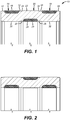
- FIG. 1 illustrates an expandable seal assembly 10 that is a tube shape having an exterior base dimension 12 measured next to a seal 14 that has an outer sealing surface 16 that extends radially beyond base dimension 12.
- a bump 20 In between seals 14 and 18 is a bump 20 that has an outer surface 22 that is axially aligned with the inside seal 24.
- Adjacent seal 24 has inside base dimension 26 with the sealing surface 29 on seal 24 extending radially inwardly beyond base dimension 26 that is disposed on opposed sides of seal 24.
- the base dimension 12 is on opposed sides of seal 14.
- seal 18 having base surfaces 28 on opposed sides.
- the outside diameter at base surfaces 12 and 28 is the same.
- Bumps 30 and 32 are disposed opposite seals 14 and 18 is the sense of axial alignment. It is preferred that the axial length of the bumps in each case approximates the axial length of the seal that is directly opposed in a radial direction. Referring to bump 20 as a typical example, the axial ends of that bump have tapered end surfaces 34 that transition to surfaces 12 and 28. The taper angle is preferably gradual at about 3-45 degrees. When the bump 20 contacts a surrounding tubular there is a volume formed adjacent seal 14 for example that allows some of the seal material to move axially into that adjacent void opposite base surface 12. The same is true on the other side adjacent seal 18 where seal material can move axially over base surface 28. Although not shown in FIG.
- end rings such as 36 and 38 preferably made of PEEK or high performance thermoplastics or metal and shown in FIG. 3 can be used in FIG. 1 to about base surfaces 12 and 28 at opposed ends of the seal assembly 10 so that seal material that is part of seals 14 and 18 can move axially into adjacent void spaces in opposed directions. The same holds true for seal 24 on the inside of seal assembly 10.
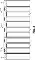
- FIG. 2 is the inverse of FIG. 1 and the above described dimensional relationships for FIG. 1 still hold for FIG. 2 .
- FIG. 3 shows three stacked seal assemblies of the type shown in FIG. 1 although those skilled in the art will understand that fewer or greater numbers of seal assemblies can be used and the orientations need not be the same for each component assembly 10.
- each unit can have one or more than one seal in the interior and/or the exterior despite the fact that the illustrated embodiment is for two seals on one side and one on the opposite side.
- One advantage is that the assemblies 10 can move independently of each other so that if the surrounding tubular is out of round or has non-uniform wall thickness the independent movement can conform to such unevenness in the surrounding tubular or for that matter in the mandrel or even in the swage that moves through the mandrel.
- Another advantage is that the seals can back each other up on discrete assemblies 10 so that in the event of a seal failure on seals on one assembly 10 the seals on the next assembly 10 can take over.
- the positioning of the bumps opposite the seal assemblies provides a nearly consistent wall thickness throughout the assembly 10. Where the wall is removed for a groove for a seal there is an offsetting bump on the opposite side of the wall.
- the structure of assembly is strengthened in the seal area and the stress is reduced making it possible to withstand greater pressure differentials, thus creates effective sealing through seal volume containment.
- the ability of some of the seal material to flow axially while being contained against the mandrel on the inside or the surrounding pipe on the outside allows for lower stress in the seal and a greater seal coverage area at the same time.
- Using an array of seal assemblies allows them to move independently to accommodate dimensional irregularities in the surrounding tubular or the mandrel inside the assembly.
- the seals extend radially adjacent base diameters on either side so that upon contact with a surrounding tubular for example the seal is compressed and some of that compressive stress is relieved in the adjacent void space in part defined by a bump that may be on one or opposed ends or the end ring as the case may be.
Landscapes
- Engineering & Computer Science (AREA)
- General Engineering & Computer Science (AREA)
- Mechanical Engineering (AREA)
- Mining & Mineral Resources (AREA)
- Life Sciences & Earth Sciences (AREA)
- Geology (AREA)
- Fluid Mechanics (AREA)
- Physics & Mathematics (AREA)
- Environmental & Geological Engineering (AREA)
- General Life Sciences & Earth Sciences (AREA)
- Geochemistry & Mineralogy (AREA)
- Architecture (AREA)
- Gasket Seals (AREA)
Claims (13)
- Ensemble de joints extensible (10), comprenant :
au moins un corps tubulaire ayant une surface de base tubulaire intérieure et extérieure (26 ; 12, 28) ; au moins un joint (14, 18, 24) disposé dans une rainure dans ladite surface de base tubulaire sur chacun d'un intérieur et d'un extérieur dudit corps tubulaire ; et une bosse (30, 32, 20) sur un côté opposé dudit corps tubulaire à partir de chacun des joints et en alignement sensiblement axial avec ceux-ci ; de sorte que ledit corps tubulaire a une épaisseur de paroi sensiblement constante sur tout l'ensemble. - Ensemble (10) selon la revendication 1, dans lequel :
chaque bosse (30, 32, 20) s'étend radialement au-delà d'une surface de base (28, 12) adjacente. - Ensemble (10) selon la revendication 2, dans lequel :
chaque bosse (30, 32, 20) a une transition d'extrémité effilée vers ladite surface de base (28, 12) adjacente. - Ensemble (10) selon la revendication 3, dans lequel :
ladite transition forme un angle de 3 à 45 degrés par rapport à ladite surface de base (12, 28) adjacente. - Ensemble (10) selon la revendication 1, dans lequel :
chaque joint (14, 18, 24) s'étend en dehors de ladite rainure et au-delà d'une dite surface de base (2, 8, 12) adjacente avant l'extension dudit corps tubulaire. - Ensemble (10) selon la revendication 1, dans lequel :
chaque joint (14, 18, 24) se déplace axialement dans au moins une direction lorsqu'il est soumis à une force de compression au moment de l'extension radiale dudit corps tubulaire. - Ensemble (10) selon la revendication 6, dans lequel :
chaque joint (14, 18, 24) se déplace axialement dans un vide défini par ladite bosse (30, 32, 20) opposée et une surface de base (28, 12) adjacente. - Ensemble (10) selon la revendication 1, comprenant en outre :
des bagues d'extrémité (36, 38) sur au moins une extrémité dudit corps tubulaire. - Ensemble (10) selon la revendication 8, dans lequel :
lesdites bagues d'extrémité (36, 39) sont réalisées en PEEK ou en thermoplastiques à hautes performances ou en métal. - Ensemble (10) selon la revendication 1, dans lequel :
un côté dudit corps tubulaire a deux joints (14, 18) et l'autre a un joint (20) . - Ensemble selon la revendication 1, dans lequel :
lesdites bosses (14, 18) qui sont sur le même côté dudit corps tubulaire s'étendent radialement sur la même distance à partir de surfaces de base (28) adjacentes. - Ensemble selon la revendication 1, dans lequel :
ledit au moins un corps tubulaire comprend une pluralité de corps tubulaires empilés entre une paire de bagues d'extrémité (36, 38). - Ensemble selon la revendication 12, dans lequel :
lesdits corps tubulaires se déplacent indépendamment au moment de l'extension pour se conformer à un mandrin au sein ou vers un tubulaire entourant, et dans lequel :
au moins un dit joint sur un dit corps tubulaire double au moins un autre joint sur un dit corps tubulaire différent.
Applications Claiming Priority (2)
| Application Number | Priority Date | Filing Date | Title |
|---|---|---|---|
| US13/872,587 US9568103B2 (en) | 2013-04-29 | 2013-04-29 | Expandable high pressure and high temperature seal |
| PCT/US2014/033995 WO2014179019A1 (fr) | 2013-04-29 | 2014-04-14 | Joint extensible à haute pression et à haute température |
Publications (3)
| Publication Number | Publication Date |
|---|---|
| EP2992252A1 EP2992252A1 (fr) | 2016-03-09 |
| EP2992252A4 EP2992252A4 (fr) | 2017-01-04 |
| EP2992252B1 true EP2992252B1 (fr) | 2018-12-05 |
Family
ID=51788616
Family Applications (1)
| Application Number | Title | Priority Date | Filing Date |
|---|---|---|---|
| EP14791111.9A Active EP2992252B1 (fr) | 2013-04-29 | 2014-04-14 | Joint extensible à haute pression et à haute température |
Country Status (7)
| Country | Link |
|---|---|
| US (1) | US9568103B2 (fr) |
| EP (1) | EP2992252B1 (fr) |
| AU (1) | AU2014260407B2 (fr) |
| BR (1) | BR112015026564B1 (fr) |
| CA (1) | CA2909529C (fr) |
| MY (1) | MY185675A (fr) |
| WO (1) | WO2014179019A1 (fr) |
Families Citing this family (10)
| Publication number | Priority date | Publication date | Assignee | Title |
|---|---|---|---|---|
| EP2952672A1 (fr) * | 2014-06-04 | 2015-12-09 | Welltec A/S | Tubulaire métallique expansible de fond |
| US20170081937A1 (en) * | 2015-09-23 | 2017-03-23 | Weatherford Technology Holdings, Llc | Downhole seal |
| CA3053711C (fr) | 2018-08-30 | 2024-01-02 | Avalon Research Ltd. | Bouchon pour colonne de production concentrique |
| CN110617154B (zh) * | 2019-09-18 | 2022-08-30 | 重庆市锋盈汽车配件有限公司 | 一种汽车发动机气缸体 |
| CN210890115U (zh) * | 2019-10-31 | 2020-06-30 | 武汉鑫华封机械制造有限责任公司 | 非金属浮动油封 |
| US11725472B2 (en) * | 2020-12-23 | 2023-08-15 | Baker Hughes Oilfield Operations Llc | Open tip downhole expansion tool |
| US12196054B2 (en) | 2022-11-30 | 2025-01-14 | Baker Hughes Oilfield Operations Llc | Seal backup and seal system |
| US12553520B2 (en) | 2024-05-13 | 2026-02-17 | Schlumberger Technology Corporation | Metal seal for dynamic downhole environments |
| WO2025240417A2 (fr) * | 2024-05-13 | 2025-11-20 | Schlumberger Technology Corporation | Ensembles joint d'étanchéité destinés à être utilisés dans un puits de forage |
| US12460515B1 (en) | 2024-07-29 | 2025-11-04 | Baker Hughes Oilfield Operations Llc | Seal arrangement for a liner hanger, method, and system |
Family Cites Families (29)
| Publication number | Priority date | Publication date | Assignee | Title |
|---|---|---|---|---|
| US3885800A (en) | 1973-04-23 | 1975-05-27 | Ato Inc | Seal ring system |
| US4615544A (en) * | 1982-02-16 | 1986-10-07 | Smith International, Inc. | Subsea wellhead system |
| US4488740A (en) * | 1982-02-19 | 1984-12-18 | Smith International, Inc. | Breech block hanger support |
| US4757860A (en) * | 1985-05-02 | 1988-07-19 | Dril-Quip, Inc. | Wellhead equipment |
| US4719971A (en) * | 1986-08-18 | 1988-01-19 | Vetco Gray Inc. | Metal-to-metal/elastomeric pack-off assembly for subsea wellhead systems |
| US5098717A (en) | 1987-12-09 | 1992-03-24 | Thames Pharmacal Co., Inc. | Method of treatment for pruritus |
| US4911245A (en) * | 1989-03-10 | 1990-03-27 | Vetco Gray Inc. | Metal seal with soft inlays |
| US5129660A (en) * | 1991-02-25 | 1992-07-14 | Cooper Industries, Inc. | Seal assembly for a well housing hanger structure |
| US5333692A (en) | 1992-01-29 | 1994-08-02 | Baker Hughes Incorporated | Straight bore metal-to-metal wellbore seal apparatus and method of sealing in a wellbore |
| US5355961A (en) * | 1993-04-02 | 1994-10-18 | Abb Vetco Gray Inc. | Metal and elastomer casing hanger seal |
| US6098717A (en) * | 1997-10-08 | 2000-08-08 | Formlock, Inc. | Method and apparatus for hanging tubulars in wells |
| US6446717B1 (en) * | 2000-06-01 | 2002-09-10 | Weatherford/Lamb, Inc. | Core-containing sealing assembly |
| US6666276B1 (en) * | 2001-10-19 | 2003-12-23 | John M. Yokley | Downhole radial set packer element |
| US7284603B2 (en) | 2001-11-13 | 2007-10-23 | Schlumberger Technology Corporation | Expandable completion system and method |
| CA2379645C (fr) | 2002-03-28 | 2004-06-01 | Westport Research Inc. | Piston alternatif avec systeme et technique de recuperation de liquide |
| US7387170B2 (en) * | 2002-04-05 | 2008-06-17 | Baker Hughes Incorporated | Expandable packer with mounted exterior slips and seal |
| CA2493669A1 (fr) * | 2002-07-24 | 2004-01-29 | Enventure Global Technology | Systeme de completion de puits double |
| US7740248B2 (en) * | 2003-09-18 | 2010-06-22 | Cameron International Corporation | Annular seal |
| US7784797B2 (en) * | 2006-05-19 | 2010-08-31 | Baker Hughes Incorporated | Seal and slip assembly for expandable downhole tools |
| US20080203672A1 (en) * | 2007-02-28 | 2008-08-28 | National Coupling Company, Inc. | Pressure-energized shaft seal |
| GB2468075B (en) * | 2007-11-05 | 2011-03-23 | Cameron Int Corp | Self-energizing annular seal |
| US8205890B2 (en) * | 2008-07-08 | 2012-06-26 | Worldwide Oilfield Machine, Inc. | Resilient high pressure metal-to-metal seal and method |
| CN201407351Y (zh) * | 2009-04-10 | 2010-02-17 | 李正心 | 转动轴出露端油封装置 |
| ATE549566T1 (de) | 2009-07-08 | 2012-03-15 | Parker Hannifin Corp | DICHTUNGSVERBINDUNG ZUM ANSCHLIEßEN VON ROHRTEILEN IN EINEM MOTORABGASSYSTEM |
| US20120193088A1 (en) * | 2011-01-31 | 2012-08-02 | Mohawk Energy Ltd. | Expandable Compliant Anchor/Seal |
| US9528352B2 (en) | 2011-02-16 | 2016-12-27 | Weatherford Technology Holdings, Llc | Extrusion-resistant seals for expandable tubular assembly |
| US9243711B2 (en) * | 2011-07-19 | 2016-01-26 | Vetco Gray Inc. | Bi-directional pressure energized axial seal and a swivel connection application |
| US20130140775A1 (en) * | 2011-12-02 | 2013-06-06 | Vetco Gray Inc. | Seal With Bellows Type Nose Ring |
| US8925639B2 (en) * | 2011-12-06 | 2015-01-06 | Vetco Gray Inc. | Seal with bellows style nose ring and radially drivable lock rings |
-
2013
- 2013-04-29 US US13/872,587 patent/US9568103B2/en active Active
-
2014
- 2014-04-14 CA CA2909529A patent/CA2909529C/fr active Active
- 2014-04-14 BR BR112015026564-2A patent/BR112015026564B1/pt active IP Right Grant
- 2014-04-14 WO PCT/US2014/033995 patent/WO2014179019A1/fr not_active Ceased
- 2014-04-14 EP EP14791111.9A patent/EP2992252B1/fr active Active
- 2014-04-14 MY MYPI2015703845A patent/MY185675A/en unknown
- 2014-04-14 AU AU2014260407A patent/AU2014260407B2/en active Active
Also Published As
| Publication number | Publication date |
|---|---|
| AU2014260407B2 (en) | 2017-04-06 |
| WO2014179019A1 (fr) | 2014-11-06 |
| AU2014260407A1 (en) | 2015-10-22 |
| CA2909529C (fr) | 2018-03-27 |
| MY185675A (en) | 2021-05-29 |
| EP2992252A1 (fr) | 2016-03-09 |
| CA2909529A1 (fr) | 2014-11-06 |
| US9568103B2 (en) | 2017-02-14 |
| BR112015026564B1 (pt) | 2021-04-06 |
| US20140319783A1 (en) | 2014-10-30 |
| EP2992252A4 (fr) | 2017-01-04 |
| BR112015026564A2 (pt) | 2017-07-25 |
Similar Documents
| Publication | Publication Date | Title |
|---|---|---|
| EP2992252B1 (fr) | Joint extensible à haute pression et à haute température | |
| CN104302868B (zh) | 封隔元件支承系统 | |
| US8678099B2 (en) | Sealing system | |
| EP2844824B1 (fr) | Tige d'étanchéité | |
| EP2893131B1 (fr) | Raccord tubulaire | |
| EP2715050B1 (fr) | Dispositif obturateur | |
| EP3152389B1 (fr) | Tubulaire métallique extensible de fond de trou | |
| EP2802732B1 (fr) | Tige de forage double emboîtée | |
| US20160369587A1 (en) | Downhole expandable metal tubular | |
| US20080296028A1 (en) | Downhole pressure chamber and method of making same | |
| EP3714129B1 (fr) | Dispositif d'outil de puits comprenant un système d'encliquetage | |
| US20140346739A1 (en) | Bullet Seal | |
| US10184302B2 (en) | Morphing tubulars | |
| CN114542006A (zh) | 密封胶筒组件及封隔器 | |
| CA2897108C (fr) | Joint de projectile de secours avec fonction de delais d'actionnement | |
| US10107066B2 (en) | Anti-creep rings and configurations for single packers |
Legal Events
| Date | Code | Title | Description |
|---|---|---|---|
| PUAI | Public reference made under article 153(3) epc to a published international application that has entered the european phase |
Free format text: ORIGINAL CODE: 0009012 |
|
| 17P | Request for examination filed |
Effective date: 20151027 |
|
| AK | Designated contracting states |
Kind code of ref document: A1 Designated state(s): AL AT BE BG CH CY CZ DE DK EE ES FI FR GB GR HR HU IE IS IT LI LT LU LV MC MK MT NL NO PL PT RO RS SE SI SK SM TR |
|
| AX | Request for extension of the european patent |
Extension state: BA ME |
|
| RIN1 | Information on inventor provided before grant (corrected) |
Inventor name: GOMEZ, LEOPOLDO, S. Inventor name: NANAWARE, GANESH, K. |
|
| DAX | Request for extension of the european patent (deleted) | ||
| A4 | Supplementary search report drawn up and despatched |
Effective date: 20161202 |
|
| RIC1 | Information provided on ipc code assigned before grant |
Ipc: F16J 9/00 20060101ALI20161128BHEP Ipc: F16J 15/00 20060101AFI20161128BHEP Ipc: F16J 15/12 20060101ALI20161128BHEP Ipc: F16J 15/24 20060101ALI20161128BHEP |
|
| STAA | Information on the status of an ep patent application or granted ep patent |
Free format text: STATUS: EXAMINATION IS IN PROGRESS |
|
| 17Q | First examination report despatched |
Effective date: 20170927 |
|
| GRAP | Despatch of communication of intention to grant a patent |
Free format text: ORIGINAL CODE: EPIDOSNIGR1 |
|
| STAA | Information on the status of an ep patent application or granted ep patent |
Free format text: STATUS: GRANT OF PATENT IS INTENDED |
|
| INTG | Intention to grant announced |
Effective date: 20180612 |
|
| RAP1 | Party data changed (applicant data changed or rights of an application transferred) |
Owner name: BAKER HUGHES, A GE COMPANY, LLC |
|
| GRAS | Grant fee paid |
Free format text: ORIGINAL CODE: EPIDOSNIGR3 |
|
| GRAA | (expected) grant |
Free format text: ORIGINAL CODE: 0009210 |
|
| STAA | Information on the status of an ep patent application or granted ep patent |
Free format text: STATUS: THE PATENT HAS BEEN GRANTED |
|
| AK | Designated contracting states |
Kind code of ref document: B1 Designated state(s): AL AT BE BG CH CY CZ DE DK EE ES FI FR GB GR HR HU IE IS IT LI LT LU LV MC MK MT NL NO PL PT RO RS SE SI SK SM TR |
|
| REG | Reference to a national code |
Ref country code: GB Ref legal event code: FG4D |
|
| REG | Reference to a national code |
Ref country code: CH Ref legal event code: EP |
|
| REG | Reference to a national code |
Ref country code: AT Ref legal event code: REF Ref document number: 1073480 Country of ref document: AT Kind code of ref document: T Effective date: 20181215 |
|
| REG | Reference to a national code |
Ref country code: IE Ref legal event code: FG4D |
|
| REG | Reference to a national code |
Ref country code: DE Ref legal event code: R096 Ref document number: 602014037501 Country of ref document: DE |
|
| REG | Reference to a national code |
Ref country code: NO Ref legal event code: T2 Effective date: 20181205 |
|
| REG | Reference to a national code |
Ref country code: NL Ref legal event code: MP Effective date: 20181205 |
|
| REG | Reference to a national code |
Ref country code: AT Ref legal event code: MK05 Ref document number: 1073480 Country of ref document: AT Kind code of ref document: T Effective date: 20181205 |
|
| REG | Reference to a national code |
Ref country code: LT Ref legal event code: MG4D |
|
| PG25 | Lapsed in a contracting state [announced via postgrant information from national office to epo] |
Ref country code: LV Free format text: LAPSE BECAUSE OF FAILURE TO SUBMIT A TRANSLATION OF THE DESCRIPTION OR TO PAY THE FEE WITHIN THE PRESCRIBED TIME-LIMIT Effective date: 20181205 Ref country code: HR Free format text: LAPSE BECAUSE OF FAILURE TO SUBMIT A TRANSLATION OF THE DESCRIPTION OR TO PAY THE FEE WITHIN THE PRESCRIBED TIME-LIMIT Effective date: 20181205 Ref country code: AT Free format text: LAPSE BECAUSE OF FAILURE TO SUBMIT A TRANSLATION OF THE DESCRIPTION OR TO PAY THE FEE WITHIN THE PRESCRIBED TIME-LIMIT Effective date: 20181205 Ref country code: ES Free format text: LAPSE BECAUSE OF FAILURE TO SUBMIT A TRANSLATION OF THE DESCRIPTION OR TO PAY THE FEE WITHIN THE PRESCRIBED TIME-LIMIT Effective date: 20181205 Ref country code: BG Free format text: LAPSE BECAUSE OF FAILURE TO SUBMIT A TRANSLATION OF THE DESCRIPTION OR TO PAY THE FEE WITHIN THE PRESCRIBED TIME-LIMIT Effective date: 20190305 Ref country code: LT Free format text: LAPSE BECAUSE OF FAILURE TO SUBMIT A TRANSLATION OF THE DESCRIPTION OR TO PAY THE FEE WITHIN THE PRESCRIBED TIME-LIMIT Effective date: 20181205 Ref country code: FI Free format text: LAPSE BECAUSE OF FAILURE TO SUBMIT A TRANSLATION OF THE DESCRIPTION OR TO PAY THE FEE WITHIN THE PRESCRIBED TIME-LIMIT Effective date: 20181205 |
|
| PG25 | Lapsed in a contracting state [announced via postgrant information from national office to epo] |
Ref country code: GR Free format text: LAPSE BECAUSE OF FAILURE TO SUBMIT A TRANSLATION OF THE DESCRIPTION OR TO PAY THE FEE WITHIN THE PRESCRIBED TIME-LIMIT Effective date: 20190306 Ref country code: RS Free format text: LAPSE BECAUSE OF FAILURE TO SUBMIT A TRANSLATION OF THE DESCRIPTION OR TO PAY THE FEE WITHIN THE PRESCRIBED TIME-LIMIT Effective date: 20181205 Ref country code: SE Free format text: LAPSE BECAUSE OF FAILURE TO SUBMIT A TRANSLATION OF THE DESCRIPTION OR TO PAY THE FEE WITHIN THE PRESCRIBED TIME-LIMIT Effective date: 20181205 Ref country code: AL Free format text: LAPSE BECAUSE OF FAILURE TO SUBMIT A TRANSLATION OF THE DESCRIPTION OR TO PAY THE FEE WITHIN THE PRESCRIBED TIME-LIMIT Effective date: 20181205 |
|
| PG25 | Lapsed in a contracting state [announced via postgrant information from national office to epo] |
Ref country code: NL Free format text: LAPSE BECAUSE OF FAILURE TO SUBMIT A TRANSLATION OF THE DESCRIPTION OR TO PAY THE FEE WITHIN THE PRESCRIBED TIME-LIMIT Effective date: 20181205 |
|
| PG25 | Lapsed in a contracting state [announced via postgrant information from national office to epo] |
Ref country code: PL Free format text: LAPSE BECAUSE OF FAILURE TO SUBMIT A TRANSLATION OF THE DESCRIPTION OR TO PAY THE FEE WITHIN THE PRESCRIBED TIME-LIMIT Effective date: 20181205 Ref country code: CZ Free format text: LAPSE BECAUSE OF FAILURE TO SUBMIT A TRANSLATION OF THE DESCRIPTION OR TO PAY THE FEE WITHIN THE PRESCRIBED TIME-LIMIT Effective date: 20181205 Ref country code: IT Free format text: LAPSE BECAUSE OF FAILURE TO SUBMIT A TRANSLATION OF THE DESCRIPTION OR TO PAY THE FEE WITHIN THE PRESCRIBED TIME-LIMIT Effective date: 20181205 Ref country code: PT Free format text: LAPSE BECAUSE OF FAILURE TO SUBMIT A TRANSLATION OF THE DESCRIPTION OR TO PAY THE FEE WITHIN THE PRESCRIBED TIME-LIMIT Effective date: 20190405 |
|
| PG25 | Lapsed in a contracting state [announced via postgrant information from national office to epo] |
Ref country code: RO Free format text: LAPSE BECAUSE OF FAILURE TO SUBMIT A TRANSLATION OF THE DESCRIPTION OR TO PAY THE FEE WITHIN THE PRESCRIBED TIME-LIMIT Effective date: 20181205 Ref country code: IS Free format text: LAPSE BECAUSE OF FAILURE TO SUBMIT A TRANSLATION OF THE DESCRIPTION OR TO PAY THE FEE WITHIN THE PRESCRIBED TIME-LIMIT Effective date: 20190405 Ref country code: EE Free format text: LAPSE BECAUSE OF FAILURE TO SUBMIT A TRANSLATION OF THE DESCRIPTION OR TO PAY THE FEE WITHIN THE PRESCRIBED TIME-LIMIT Effective date: 20181205 Ref country code: SM Free format text: LAPSE BECAUSE OF FAILURE TO SUBMIT A TRANSLATION OF THE DESCRIPTION OR TO PAY THE FEE WITHIN THE PRESCRIBED TIME-LIMIT Effective date: 20181205 Ref country code: SK Free format text: LAPSE BECAUSE OF FAILURE TO SUBMIT A TRANSLATION OF THE DESCRIPTION OR TO PAY THE FEE WITHIN THE PRESCRIBED TIME-LIMIT Effective date: 20181205 |
|
| REG | Reference to a national code |
Ref country code: DE Ref legal event code: R097 Ref document number: 602014037501 Country of ref document: DE |
|
| PLBE | No opposition filed within time limit |
Free format text: ORIGINAL CODE: 0009261 |
|
| STAA | Information on the status of an ep patent application or granted ep patent |
Free format text: STATUS: NO OPPOSITION FILED WITHIN TIME LIMIT |
|
| PG25 | Lapsed in a contracting state [announced via postgrant information from national office to epo] |
Ref country code: SI Free format text: LAPSE BECAUSE OF FAILURE TO SUBMIT A TRANSLATION OF THE DESCRIPTION OR TO PAY THE FEE WITHIN THE PRESCRIBED TIME-LIMIT Effective date: 20181205 Ref country code: DK Free format text: LAPSE BECAUSE OF FAILURE TO SUBMIT A TRANSLATION OF THE DESCRIPTION OR TO PAY THE FEE WITHIN THE PRESCRIBED TIME-LIMIT Effective date: 20181205 |
|
| REG | Reference to a national code |
Ref country code: DE Ref legal event code: R119 Ref document number: 602014037501 Country of ref document: DE |
|
| 26N | No opposition filed |
Effective date: 20190906 |
|
| REG | Reference to a national code |
Ref country code: CH Ref legal event code: PL |
|
| REG | Reference to a national code |
Ref country code: BE Ref legal event code: MM Effective date: 20190430 |
|
| PG25 | Lapsed in a contracting state [announced via postgrant information from national office to epo] |
Ref country code: LU Free format text: LAPSE BECAUSE OF NON-PAYMENT OF DUE FEES Effective date: 20190414 Ref country code: MC Free format text: LAPSE BECAUSE OF FAILURE TO SUBMIT A TRANSLATION OF THE DESCRIPTION OR TO PAY THE FEE WITHIN THE PRESCRIBED TIME-LIMIT Effective date: 20181205 |
|
| PG25 | Lapsed in a contracting state [announced via postgrant information from national office to epo] |
Ref country code: DE Free format text: LAPSE BECAUSE OF NON-PAYMENT OF DUE FEES Effective date: 20191101 Ref country code: CH Free format text: LAPSE BECAUSE OF NON-PAYMENT OF DUE FEES Effective date: 20190430 Ref country code: LI Free format text: LAPSE BECAUSE OF NON-PAYMENT OF DUE FEES Effective date: 20190430 |
|
| PG25 | Lapsed in a contracting state [announced via postgrant information from national office to epo] |
Ref country code: BE Free format text: LAPSE BECAUSE OF NON-PAYMENT OF DUE FEES Effective date: 20190430 Ref country code: FR Free format text: LAPSE BECAUSE OF NON-PAYMENT OF DUE FEES Effective date: 20190430 |
|
| PG25 | Lapsed in a contracting state [announced via postgrant information from national office to epo] |
Ref country code: TR Free format text: LAPSE BECAUSE OF FAILURE TO SUBMIT A TRANSLATION OF THE DESCRIPTION OR TO PAY THE FEE WITHIN THE PRESCRIBED TIME-LIMIT Effective date: 20181205 |
|
| PG25 | Lapsed in a contracting state [announced via postgrant information from national office to epo] |
Ref country code: IE Free format text: LAPSE BECAUSE OF NON-PAYMENT OF DUE FEES Effective date: 20190414 |
|
| PG25 | Lapsed in a contracting state [announced via postgrant information from national office to epo] |
Ref country code: CY Free format text: LAPSE BECAUSE OF FAILURE TO SUBMIT A TRANSLATION OF THE DESCRIPTION OR TO PAY THE FEE WITHIN THE PRESCRIBED TIME-LIMIT Effective date: 20181205 |
|
| PG25 | Lapsed in a contracting state [announced via postgrant information from national office to epo] |
Ref country code: HU Free format text: LAPSE BECAUSE OF FAILURE TO SUBMIT A TRANSLATION OF THE DESCRIPTION OR TO PAY THE FEE WITHIN THE PRESCRIBED TIME-LIMIT; INVALID AB INITIO Effective date: 20140414 Ref country code: MT Free format text: LAPSE BECAUSE OF FAILURE TO SUBMIT A TRANSLATION OF THE DESCRIPTION OR TO PAY THE FEE WITHIN THE PRESCRIBED TIME-LIMIT Effective date: 20181205 |
|
| PG25 | Lapsed in a contracting state [announced via postgrant information from national office to epo] |
Ref country code: MK Free format text: LAPSE BECAUSE OF FAILURE TO SUBMIT A TRANSLATION OF THE DESCRIPTION OR TO PAY THE FEE WITHIN THE PRESCRIBED TIME-LIMIT Effective date: 20181205 |
|
| P01 | Opt-out of the competence of the unified patent court (upc) registered |
Effective date: 20230526 |
|
| PGFP | Annual fee paid to national office [announced via postgrant information from national office to epo] |
Ref country code: GB Payment date: 20260319 Year of fee payment: 13 |
|
| PGFP | Annual fee paid to national office [announced via postgrant information from national office to epo] |
Ref country code: NO Payment date: 20260320 Year of fee payment: 13 |