EP2992776A1 - Gehäuse und vorrichtung damit - Google Patents
Gehäuse und vorrichtung damit Download PDFInfo
- Publication number
- EP2992776A1 EP2992776A1 EP15182620.3A EP15182620A EP2992776A1 EP 2992776 A1 EP2992776 A1 EP 2992776A1 EP 15182620 A EP15182620 A EP 15182620A EP 2992776 A1 EP2992776 A1 EP 2992776A1
- Authority
- EP
- European Patent Office
- Prior art keywords
- coil
- case
- edge
- receiving coil
- rear surface
- Prior art date
- Legal status (The legal status is an assumption and is not a legal conclusion. Google has not performed a legal analysis and makes no representation as to the accuracy of the status listed.)
- Granted
Links
Images



Classifications
-
- A—HUMAN NECESSITIES
- A45—HAND OR TRAVELLING ARTICLES
- A45C—PURSES; LUGGAGE; HAND CARRIED BAGS
- A45C11/00—Receptacles for purposes not provided for in groups A45C1/00-A45C9/00
-
- H—ELECTRICITY
- H01—ELECTRIC ELEMENTS
- H01Q—ANTENNAS, i.e. RADIO AERIALS
- H01Q1/00—Details of, or arrangements associated with, antennas
- H01Q1/12—Supports; Mounting means
- H01Q1/22—Supports; Mounting means by structural association with other equipment or articles
- H01Q1/2208—Supports; Mounting means by structural association with other equipment or articles associated with components used in interrogation type services, i.e. in systems for information exchange between an interrogator/reader and a tag/transponder, e.g. in Radio Frequency Identification [RFID] systems
-
- H—ELECTRICITY
- H01—ELECTRIC ELEMENTS
- H01Q—ANTENNAS, i.e. RADIO AERIALS
- H01Q1/00—Details of, or arrangements associated with, antennas
- H01Q1/12—Supports; Mounting means
- H01Q1/22—Supports; Mounting means by structural association with other equipment or articles
- H01Q1/24—Supports; Mounting means by structural association with other equipment or articles with receiving set
- H01Q1/241—Supports; Mounting means by structural association with other equipment or articles with receiving set used in mobile communications, e.g. GSM
- H01Q1/242—Supports; Mounting means by structural association with other equipment or articles with receiving set used in mobile communications, e.g. GSM specially adapted for hand-held use
- H01Q1/243—Supports; Mounting means by structural association with other equipment or articles with receiving set used in mobile communications, e.g. GSM specially adapted for hand-held use with built-in antennas
-
- H—ELECTRICITY
- H01—ELECTRIC ELEMENTS
- H01Q—ANTENNAS, i.e. RADIO AERIALS
- H01Q7/00—Loop antennas with a substantially uniform current distribution around the loop and having a directional radiation pattern in a plane perpendicular to the plane of the loop
-
- H—ELECTRICITY
- H02—GENERATION; CONVERSION OR DISTRIBUTION OF ELECTRIC POWER
- H02J—ELECTRIC POWER NETWORKS; CIRCUIT ARRANGEMENTS OR SYSTEMS FOR SUPPLYING OR DISTRIBUTING ELECTRIC POWER; SYSTEMS FOR STORING ELECTRIC ENERGY
- H02J50/00—Circuit arrangements or systems for wireless supply or distribution of electric power
- H02J50/10—Circuit arrangements or systems for wireless supply or distribution of electric power using inductive coupling
-
- H—ELECTRICITY
- H02—GENERATION; CONVERSION OR DISTRIBUTION OF ELECTRIC POWER
- H02J—ELECTRIC POWER NETWORKS; CIRCUIT ARRANGEMENTS OR SYSTEMS FOR SUPPLYING OR DISTRIBUTING ELECTRIC POWER; SYSTEMS FOR STORING ELECTRIC ENERGY
- H02J50/00—Circuit arrangements or systems for wireless supply or distribution of electric power
- H02J50/80—Circuit arrangements or systems for wireless supply or distribution of electric power involving the exchange of data, concerning supply or distribution of electric power, between transmitting devices and receiving devices
-
- H—ELECTRICITY
- H04—ELECTRIC COMMUNICATION TECHNIQUE
- H04B—TRANSMISSION
- H04B5/00—Near-field transmission systems, e.g. inductive or capacitive transmission systems
- H04B5/20—Near-field transmission systems, e.g. inductive or capacitive transmission systems characterised by the transmission technique; characterised by the transmission medium
- H04B5/24—Inductive coupling
- H04B5/26—Inductive coupling using coils
-
- H—ELECTRICITY
- H04—ELECTRIC COMMUNICATION TECHNIQUE
- H04B—TRANSMISSION
- H04B5/00—Near-field transmission systems, e.g. inductive or capacitive transmission systems
- H04B5/70—Near-field transmission systems, e.g. inductive or capacitive transmission systems specially adapted for specific purposes
- H04B5/79—Near-field transmission systems, e.g. inductive or capacitive transmission systems specially adapted for specific purposes for data transfer in combination with power transfer
-
- A—HUMAN NECESSITIES
- A45—HAND OR TRAVELLING ARTICLES
- A45C—PURSES; LUGGAGE; HAND CARRIED BAGS
- A45C11/00—Receptacles for purposes not provided for in groups A45C1/00-A45C9/00
- A45C11/002—Receptacles for purposes not provided for in groups A45C1/00-A45C9/00 for storing portable handheld communication devices, e.g. pagers or smart phones
-
- A—HUMAN NECESSITIES
- A45—HAND OR TRAVELLING ARTICLES
- A45C—PURSES; LUGGAGE; HAND CARRIED BAGS
- A45C11/00—Receptacles for purposes not provided for in groups A45C1/00-A45C9/00
- A45C11/003—Receptacles for purposes not provided for in groups A45C1/00-A45C9/00 for storing portable computing devices, e.g. laptops, tablets or calculators
-
- H—ELECTRICITY
- H01—ELECTRIC ELEMENTS
- H01M—PROCESSES OR MEANS, e.g. BATTERIES, FOR THE DIRECT CONVERSION OF CHEMICAL ENERGY INTO ELECTRICAL ENERGY
- H01M10/00—Secondary cells; Manufacture thereof
- H01M10/42—Methods or arrangements for servicing or maintenance of secondary cells or secondary half-cells
- H01M10/46—Accumulators structurally combined with charging apparatus
-
- H—ELECTRICITY
- H02—GENERATION; CONVERSION OR DISTRIBUTION OF ELECTRIC POWER
- H02J—ELECTRIC POWER NETWORKS; CIRCUIT ARRANGEMENTS OR SYSTEMS FOR SUPPLYING OR DISTRIBUTING ELECTRIC POWER; SYSTEMS FOR STORING ELECTRIC ENERGY
- H02J7/00—Circuit arrangements for charging or discharging batteries or for supplying loads from batteries
- H02J7/40—Circuit arrangements for charging or discharging batteries or for supplying loads from batteries characterised by the exchange of charge or discharge related data
- H02J7/42—Circuit arrangements for charging or discharging batteries or for supplying loads from batteries characterised by the exchange of charge or discharge related data with electronic devices having internal batteries, e.g. mobile phones
-
- H—ELECTRICITY
- H02—GENERATION; CONVERSION OR DISTRIBUTION OF ELECTRIC POWER
- H02J—ELECTRIC POWER NETWORKS; CIRCUIT ARRANGEMENTS OR SYSTEMS FOR SUPPLYING OR DISTRIBUTING ELECTRIC POWER; SYSTEMS FOR STORING ELECTRIC ENERGY
- H02J7/00—Circuit arrangements for charging or discharging batteries or for supplying loads from batteries
- H02J7/70—Circuit arrangements for charging or discharging batteries or for supplying loads from batteries characterised by the mechanical construction
-
- H—ELECTRICITY
- H04—ELECTRIC COMMUNICATION TECHNIQUE
- H04B—TRANSMISSION
- H04B1/00—Details of transmission systems, not covered by a single one of groups H04B3/00 - H04B13/00; Details of transmission systems not characterised by the medium used for transmission
- H04B1/38—Transceivers, i.e. devices in which transmitter and receiver form a structural unit and in which at least one part is used for functions of transmitting and receiving
- H04B1/3827—Portable transceivers
- H04B1/3888—Arrangements for carrying or protecting transceivers
-
- Y—GENERAL TAGGING OF NEW TECHNOLOGICAL DEVELOPMENTS; GENERAL TAGGING OF CROSS-SECTIONAL TECHNOLOGIES SPANNING OVER SEVERAL SECTIONS OF THE IPC; TECHNICAL SUBJECTS COVERED BY FORMER USPC CROSS-REFERENCE ART COLLECTIONS [XRACs] AND DIGESTS
- Y02—TECHNOLOGIES OR APPLICATIONS FOR MITIGATION OR ADAPTATION AGAINST CLIMATE CHANGE
- Y02E—REDUCTION OF GREENHOUSE GAS [GHG] EMISSIONS, RELATED TO ENERGY GENERATION, TRANSMISSION OR DISTRIBUTION
- Y02E60/00—Enabling technologies; Technologies with a potential or indirect contribution to GHG emissions mitigation
- Y02E60/10—Energy storage using batteries
Definitions
- This application relates to a case including a coil for receiving power wirelessly or performing near-field communication, and an apparatus including the same.
- wireless power reception technology is increasingly being demanded in mobile devices.
- near-field communication functionality is also being demanded in mobile devices.
- Mobile devices such as cellular phones, tablets, and other mobile devices have increasingly been provided with metal cases due to a customer demand.
- a rear surface of the mobile device is formed by a metal case, even in the case that a coil for wirelessly receiving power or performing near-field communication is disposed in the metal case, the power may not be wirelessly received or data may not be transmitted and received due to the metal case.
- a case in one general aspect, includes a casing region made of metal and configured to cover at least a portion of an apparatus; and a coil electrically insulated from the casing region and having a ring shape or a polygonal shape having ends separated from each other, the coil being configured to be disposed outside the apparatus.
- the casing region may include a region corresponding to a rear surface of the apparatus.
- the coil may be configured to substantially surround an edge of the apparatus.
- the coil may be disposed in a position corresponding to an edge of the rear surface of the apparatus.
- the coil may be constituted by a single conductive wire.
- the coil may include two or more turns.
- the coil may have a length of 95% or more of a length of an edge of the casing region.
- the case may further include an insulating portion disposed between the casing region and the coil.
- the coil may be configured to receive power wirelessly.
- the coil may be configured to receive or transmit data wirelessly.
- an apparatus in another general aspect, includes a body; and a case including a casing region made of metal and covering at least a portion of the body, and a coil electrically insulated from the casing region and having a ring shape or a polygonal shape having ends separated from each other, the coil being disposed outside the body.
- the body may include a wireless charging module configured to rectify power wirelessly received through the coil to charge a battery with power.
- the body may include a near-field communication (NFC) module configured to transmit and receive data through the coil.
- NFC near-field communication
- the body may include a wireless charging module configured to rectify power wirelessly received through the coil to charge a battery with power; a near-field communication (NFC) module configured to transmit and receive data through the coil; and a switch portion configured to selectively connect the coil to the NFC module or the wireless charging module in response to a signal received by the coil.
- a wireless charging module configured to rectify power wirelessly received through the coil to charge a battery with power
- NFC near-field communication
- the coil may substantially surround an edge of the body.
- the coil may be disposed along an edge of a rear surface of the body.
- a case of an apparatus in another general aspect, includes a metal portion constituting at least a portion of a rear surface of the apparatus; and a coil electrically insulated from the metal portion and constituting a portion of an exterior surface of the apparatus.
- the coil may have two ends separated by a gap, and may constitute a portion of an edge surface of the apparatus, or a portion of the rear surface of the apparatus substantially surrounding the metal portion.
- the coil may constitute a portion of an edge surface of the apparatus; and the case may further include an insulating portion constituting another portion of the side surface of the apparatus and being disposed between the coil and the metal portion to electrically insulate the coil from the metal portion.
- the coil may constitute another portion of the rear surface of the apparatus substantially surrounding the metal portion; and the case may further include an insulating portion constituting another portion of the rear surface of the apparatus and being disposed between the coil and the metal portion to electrically insulate the coil from the metal portion.
- FIG. 1 is a view illustrating an example of an exterior configuration of an apparatus 100, and illustrates a perspective view of a rear surface of the apparatus 100 in a case in which the apparatus 100 is a mobile device such as a smartphone.
- reference numeral 110 denotes a receiving coil formed on a side surface of the apparatus 100
- reference numerals 120-1 and 120-2 denote insulating portions
- reference numeral 130 denotes a rear surface of the apparatus.
- a portion of the case of the apparatus 100 is formed by the receiving coil 110, the insulating portions 120-1 and 120-2, and the rear surface 130.
- the rear surface 130 is a casing region that surrounds at least a portion of the apparatus 100.
- the receiving coil 110 is formed along an edge of the apparatus 100, thereby allowing the apparatus 100 to receive power wirelessly.
- the receiving coil 110 is a single conductive wire formed along the edge of the apparatus 100.
- FIG. 1 illustrates a case in which the receiving coil 110 is a single conductive wire formed across almost the entire edge of the apparatus 100, the receiving coil 110 may also be formed across the entire edge and may also be formed only in a portion of the edge.
- the receiving coil 110 may be formed to have a large number of turns along the edge of the apparatus 100.
- the receiving coil 110 may have a ring shape or a polygonal shape having ends that are separated from each other.
- the insulating portion 120-1 is disposed between the receiving coil 110 and the rear surface 130 of the apparatus 100.
- the receiving coil 110 and the rear surface 130 of the apparatus 100 made of metal are electrically insulated from each other.
- the insulating portion 120-2 is also disposed between the receiving coil 110 and a front surface of the apparatus 100. However, in a case in which a material of the front surface of the apparatus 100 is not made of metal, the insulating portion 120-2 may be omitted.
- the edge of the apparatus 100 may include the insulating portions 120-1 and 120-2 and the receiving coil 110.
- other portions of the edge of the apparatus 100 that is, a portion thereof between the insulating portion 120-1 and the rear surface 130 of the apparatus 100 and a portion thereof between the insulating portion 120-2 and the front surface of the apparatus 100 may be made of metal.
- Ends A1 and B1 of the receiving coil 110 are connected to an internal circuit of the apparatus.
- FIG. 1 illustrates a case in which the receiving coil 110 is formed separately on the edge of the apparatus 100
- the edge of the apparatus 100 may be formed of metal and may also be used as a receiving coil for receiving power wirelessly.
- the receiving coil 110 may be formed using a method of forming the edge of the apparatus 100 using metal and then forming the insulating portions 120-1 and 120-2.
- the case of the apparatus 100 including the receiving coil 110, the insulating portions 120-1 and 120-2, and the rear surface 130 of the apparatus 100 may be integrally formed by a method such as insert injection molding, or any other suitable method.
- the ends A1 and B1 of the receiving coil 110 may be provided with a terminal or a lead wire that is electrically connected to the internal circuit of the apparatus 100.
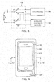
- FIG. 2 is a view illustrating another example of an exterior configuration of an apparatus 101, and illustrates a rear surface of the apparatus 101 in a case in which the apparatus 101 is a mobile device such as a smartphone.
- reference numeral 111 denotes a receiving coil formed on a rear surface of the apparatus 101
- reference numerals 121-1 and 121-2 denote insulating portions
- reference numeral 131 denotes the rear surface of the apparatus 101.
- a portion of the case of the apparatus 101 is formed by the receiving coil 111, the insulating portions 121-1 and 121-2, and the rear surface 131.
- the rear surface 131 is a casing region that surrounds at least a portion of the apparatus 101.
- the receiving coil 111 is formed along an edge of the rear surface 131 of the apparatus 101, thereby allowing the apparatus 101 to receive power wirelessly.
- the receiving coil 111 is a single conductive wire formed along the edge of the rear surface 131 of the apparatus 101.
- FIG. 2 illustrates a case in which the receiving coil 111 is a single conductive wire formed across almost the entire edge of the rear surface 131 of the apparatus 101, the receiving coil 110 may also be formed across the entire edge and may also only be formed in a portion of the edge.
- the receiving coil 111 may be formed to have a large number of turns along the edge of the rear surface 131 of the apparatus 101.
- the receiving coil 111 may have a ring shape or a polygonal shape having ends that are separated from each other.
- the insulating portions 121-1 and 121-2 are disposed between the receiving coil 111 and the rear surface 131 of the apparatus 101. As a result, the receiving coil 111 and the rear surface 131 of the apparatus 101 made of metal are electrically insulated from each other.
- the insulating portion 121-2 may be omitted.
- Ends A2 and B2 of the receiving coil 111 are connected to an internal circuit of the apparatus.
- the case of the apparatus 101 including the receiving coil 111, the insulating portions 121-1 and 121-2, and the rear surface 131 of the apparatus 101 may be integrally formed by a method such as insert injection molding, or any other suitable method.
- the ends A2 and B2 of the receiving coil 111 may be provided with a terminal or a lead wire that is electrically connected to the internal circuit of the apparatus 101.
- FIG. 3 is a view illustrating an example of an internal circuit of the apparatus.
- the body of the apparatus includes a printed circuit board (PCB) including the internal circuit, and in the example in FIG. 3 , the internal circuit of the apparatus includes a capacitor C, a switch portion 140, a near-field communication (NFC) module 150, and a wireless charging module 160.
- PCB printed circuit board
- NFC near-field communication
- L denotes a receiving coil, for example, the receiving coil 110 of FIG. 1 or the receiving coil 111 of FIG. 2 .
- the receiving coil L receives power wirelessly from an external power source.
- the receiving coil L may also wirelessly receive a data signal in addition to the power.
- the receiving coil L and the capacitor C form a resonance tank.
- the switch portion 140 includes switches S1 and S2, and transfers the power wirelessly received by the receiving coil L to the wireless charging module 160, or transfers the data signal received by the receiving coil L to the NFC module 150.
- the switches S1 and S2 of the switch portion 140 may be controlled in response to an input from a user, and may also be controlled according to an amplitude of the signal received by the receiving coil L.
- the signal received by the receiving coil L may be determined to be the power that is wirelessly received, and the switches S1 and S2 may be controlled to connect the switch S1 to a terminal b1 and connect the switch S2 to a terminal b2 to connect the receiving coil L and the capacitor C to the wireless charging module 160.
- the signal received by the receiving coil L may be determined to be the data signal, and the switches S1 and S2 may be controlled to connect the switch S1 to a terminal a1 and connect the switch S2 to a terminal a2 to connect the receiving coil L and the capacitor C to the NFC module 150.
- the NFC module 150 enables the apparatus to transmit and receive data to and from other external apparatuses.
- the wireless charging module 160 may include a rectifier, a regulator, and other charging components, and may transfer the power that is wirelessly received to a battery (not illustrated) or other energy storage device of the apparatus.
- FIG. 3 illustrates a case in which the switch portion 140 includes two switches S1 and S2, the switch S2 may be omitted in a case in which a terminal a2 and a terminal b2 are connected to a common ground.
- FIGS. 4 through 7 are views illustrating examples of configurations in which an apparatus wirelessly receives power from a wireless power transmitter 200.
- FIG. 4 illustrates a plan view of an apparatus in a case in which the apparatus has the configuration of FIG. 1 or FIG. 2
- FIG. 5 illustrates a cross-sectional view of an apparatus in the case in which the apparatus has the configuration of FIG. 1
- FIGS. 6 and 7 illustrate cross-sectional views of an apparatus in a case in which the apparatus has the configuration of FIG. 2 .
- FIGS. 4 illustrates a plan view of an apparatus in a case in which the apparatus has the configuration of FIG. 1 or FIG. 2
- FIG. 5 illustrates a cross-sectional view of an apparatus in the case in which the apparatus has the configuration of FIG. 1
- FIGS. 6 and 7 illustrate cross-sectional views of an apparatus in a case in which the apparatus has the configuration of FIG. 2 .
- FIGS. 4 illustrates a plan view of an apparatus in a case in which the apparatus has the configuration
- reference numeral 210 denotes a transmitting coil of the wireless power transmitter 200
- reference numeral 220 denotes a power source portion of the wireless power transmitter 200
- reference numeral 230 denotes a ferrite sheet of the wireless power transmitter 200
- reference numeral 240 denotes a case of the wireless power transmitter 200.
- the transmitting coil 210 of the wireless power transmitter 200 is formed to surround the receiving coil 110 of the apparatus 100.
- the receiving coil 110 of the apparatus 100 is disposed within the transmitting coil 210 of the wireless power transmitter 200.
- FIG. 4 illustrates a case in which the transmitting coil 210 has a single winding
- the transmitting coil 210 may have a two or more windings.
- Table 1 illustrates simulation results for self-inductances of the receiving coil 110 ( FIGS. 1 and 4 ), mutual inductances between the receiving coil 110 and the transmitting coil 210 ( FIG. 4 ), and coupling coefficients between the receiving coil 110 and the transmitting coil 210 according to distances between the ends A1 and B1 ( FIG. 1 ) of the receiving coil 110 in the apparatus 100 having an edge length of 384 mm.
- the edge length is a length measured along the entire edge of the apparatus 100.
- the self-inductance, the mutual inductance, and the coupling coefficient barely change up to the distance between the ends A1 and B1 of the receiving coil 110 of 20 mm, which is about 5% of the edge length of 384 mm of the apparatus, as compared to a case in which the distance between the ends A1 and B1 of the receiving coil 110 is 0 mm, that is, a case in which the receiving coil entirely surrounds the edge when viewed from above.
- the receiving coil is formed along 95% or more of the edge, a sufficiently high value of wireless charging efficiency may be achieved.
- FIG. 5 illustrates an example of a configuration in which the apparatus 100 wirelessly receives power from the wireless power transmitter 200, and illustrates a cross-sectional view of a case in which the apparatus 100 having the configuration of FIG. 1 is disposed on the wireless power transmitter 200 to wirelessly receive power.
- the apparatus 100 includes the rear surface 130, the insulating portions 120-1 and 120-2, the receiving coil 110, a front surface 133, and a body 170.
- the receiving coil 110 of the apparatus 100 is disposed outside the rear surface 130 of the apparatus 100 made of metal.
- the insulating portion 120-1 is disposed between the receiving coil 110 and the rear surface 130 of the apparatus 100.
- the insulating portion 120-2 is disposed between the receiving coil 110 and the front surface 133 of the apparatus 100.
- the front surface 133 of the apparatus 100 is not made of metal, there is no need to insulate the front surface 133 of the apparatus 100 and the receiving coil 110 from each other, so the insulating portion 120-2 may be omitted.
- the front surface 133 of the apparatus 100 which is provided to protect a display device, is made of a transparent material.
- the front surface 133 of the apparatus 100 may also be extended to portions of the side surface of the apparatus 100.
- the capacitor C, the switch portion 140, the NFC module 150, and the wireless charging module 160 illustrated in FIG. 3 are disposed in the body 170 of the apparatus 100.
- the transmitting coil 210 of the wireless power transmitter 200 is disposed outside the receiving coil 110 of the apparatus 100.
- FIGS. 6 and 7 illustrate examples of a configuration in which the apparatus wirelessly receives power from the wireless power transmitter, and illustrate cross-sectional views of the apparatus in a case in which the apparatus having the configuration of FIG. 2 is disposed on the wireless power transmitter to wirelessly receive power.
- an apparatus 101 includes include a rear surface 131, a receiving coil 111, insulating portions 121-1 and 121-2, an edge 135, a front surface 134, and a body 171.
- an apparatus 102 includes a rear surface 131-1, a receiving coil 112, an insulating portion 122, an edge 135-1, a front surface 134-1, and a body 171-1.
- the receiving coil 111 or 112 is disposed outside the rear surface 131 or 131-1 of the apparatus 101 or 102.
- the insulating portion 121-1 or 122 is disposed between the receiving coil 111 or 112 and the rear surface 131 or 131-1 of the apparatus 101 or 102.
- the insulating portion 121-2 is disposed between the edge 135 of the apparatus 101 and the receiving coil 111.
- the insulating portion 121-2 in FIG. 6 not disposed between the edge 135-1 of the apparatus 102 and the receiving coil 112.
- the front surface 134 or 134-1 of the apparatus 101 or 102 which is to protect a display device, is made of a transparent material.
- the front surface 134 or 134-1 of the apparatus 101 or 102 may also be extended to portions of the side surface of the apparatus 101 or 102.
- the capacitor C, the switch portion 140, the NFC module 150, and the wireless charging module 160 illustrated in FIG. 3 are disposed in the body 171 or 171-1 of the apparatus 101 or 102.
- the transmitting coil 210 of the wireless power transmitter 200 is disposed outside the receiving coil 111 or 112 of the apparatus 101 or 102.
- the apparatus is able to wirelessly receive power transmitted by the transmitting coil of the wireless power transmitter.
- the apparatus is able to wirelessly receive power or transmit and receive data without affecting a design of the apparatus even in a case in which the metal case is used.
Landscapes
- Engineering & Computer Science (AREA)
- Computer Networks & Wireless Communication (AREA)
- Power Engineering (AREA)
- Signal Processing (AREA)
- Charge And Discharge Circuits For Batteries Or The Like (AREA)
- Near-Field Transmission Systems (AREA)
Applications Claiming Priority (2)
| Application Number | Priority Date | Filing Date | Title |
|---|---|---|---|
| KR20140117835 | 2014-09-04 | ||
| KR1020150056927A KR101681412B1 (ko) | 2014-09-04 | 2015-04-23 | 케이스 및 이를 포함하는 기기 |
Publications (2)
| Publication Number | Publication Date |
|---|---|
| EP2992776A1 true EP2992776A1 (de) | 2016-03-09 |
| EP2992776B1 EP2992776B1 (de) | 2019-11-06 |
Family
ID=54010959
Family Applications (1)
| Application Number | Title | Priority Date | Filing Date |
|---|---|---|---|
| EP15182620.3A Active EP2992776B1 (de) | 2014-09-04 | 2015-08-27 | Gehäuse und vorrichtung damit |
Country Status (3)
| Country | Link |
|---|---|
| US (1) | US20160072337A1 (de) |
| EP (1) | EP2992776B1 (de) |
| CN (1) | CN105405578B (de) |
Cited By (1)
| Publication number | Priority date | Publication date | Assignee | Title |
|---|---|---|---|---|
| WO2017027872A1 (en) * | 2015-08-13 | 2017-02-16 | Witricity Corporation | Wireless power enabled enclosures for mobile devices |
Families Citing this family (11)
| Publication number | Priority date | Publication date | Assignee | Title |
|---|---|---|---|---|
| USD795184S1 (en) * | 2015-08-12 | 2017-08-22 | Samsung Electronics Co., Ltd. | Wireless charger for electronic device |
| US10361588B2 (en) * | 2015-12-07 | 2019-07-23 | Qualcomm Incorporated | Coupled resonator in a metal back cover |
| EP3229335B1 (de) * | 2016-04-06 | 2019-02-06 | Vestel Elektronik Sanayi ve Ticaret A.S. | Abdeckung, mobile vorrichtung und energieverwaltungsverfahren |
| WO2018028486A1 (en) | 2016-08-08 | 2018-02-15 | Guangdong Oppo Mobile Telecommunications Corp., Ltd. | Housing, method for manufacturing housing, and mobile terminal having housing |
| US10897148B2 (en) * | 2016-09-23 | 2021-01-19 | Apple Inc. | Wireless charging mats with multi-layer transmitter coil arrangements |
| KR20180044562A (ko) * | 2016-10-24 | 2018-05-03 | 삼성전기주식회사 | 무선 전력 수신 장치 |
| WO2018120921A1 (en) | 2016-12-29 | 2018-07-05 | Guangdong Oppo Mobile Telecommunications Corp., Ltd. | Mobile terminal |
| KR102119591B1 (ko) | 2017-09-14 | 2020-06-05 | 주식회사 아모센스 | 무선전력 송신장치 |
| CN107994317B (zh) * | 2017-11-21 | 2020-05-08 | Oppo广东移动通信有限公司 | 一种壳体、天线装置以及移动终端 |
| US20190215984A1 (en) | 2018-01-09 | 2019-07-11 | Aptiv Technologies Limited | Wireless device charger with cooling device |
| US20230187973A1 (en) * | 2021-12-14 | 2023-06-15 | Datalogic Ip Tech S.R.L. | Resonant wireless power transfer charging pad for unplanar devices |
Citations (4)
| Publication number | Priority date | Publication date | Assignee | Title |
|---|---|---|---|---|
| US20120329535A1 (en) * | 2011-06-22 | 2012-12-27 | Bill Kuo | Screw-free metallic jacket for mobile phone |
| WO2013102901A1 (en) * | 2012-01-05 | 2013-07-11 | Powermat Technologies Ltd | Integrated inductive power receiver and near field communicator |
| US20140077669A1 (en) * | 2012-09-18 | 2014-03-20 | Myungsoo CHOI | Cover for mobile terminal |
| US20140159502A1 (en) * | 2011-09-02 | 2014-06-12 | Fujitsu Limited | Power transmission apparatus |
Family Cites Families (109)
| Publication number | Priority date | Publication date | Assignee | Title |
|---|---|---|---|---|
| US4374354A (en) * | 1981-06-23 | 1983-02-15 | Teledyne Industries, Inc. | Rechargeable electric portable appliance |
| EP0977215A3 (de) * | 1996-08-09 | 2000-12-06 | SUMITOMO WIRING SYSTEMS, Ltd. | Verbinderanordnung zum Laden eines elektrischen Fahrzeugs |
| US5966799A (en) * | 1997-04-01 | 1999-10-19 | Motorola, Inc. | Method of molding free-floating insert |
| US7478108B2 (en) * | 1999-12-06 | 2009-01-13 | Micro Strain, Inc. | Data collection using sensing units and separate control units with all power derived from the control units |
| US6810275B2 (en) * | 2000-12-20 | 2004-10-26 | Motorola, Inc. | Hand-held communication device with vertically oriented antenna |
| JP3905418B2 (ja) * | 2001-05-18 | 2007-04-18 | セイコーインスツル株式会社 | 電源装置および電子機器 |
| US6894456B2 (en) * | 2001-11-07 | 2005-05-17 | Quallion Llc | Implantable medical power module |
| US6822609B2 (en) * | 2002-03-15 | 2004-11-23 | Etenna Corporation | Method of manufacturing antennas using micro-insert-molding techniques |
| US6839029B2 (en) * | 2002-03-15 | 2005-01-04 | Etenna Corporation | Method of mechanically tuning antennas for low-cost volume production |
| KR20030090477A (ko) * | 2002-05-21 | 2003-11-28 | 이환덕 | 일체형 가변 인서트 몰딩 제조방법 및 몰딩 부품 |
| JP4539038B2 (ja) * | 2003-06-30 | 2010-09-08 | ソニー株式会社 | データ通信装置 |
| DE102004017832B3 (de) * | 2004-04-13 | 2005-10-20 | Siemens Audiologische Technik | Hörgerät |
| DE102004062178B4 (de) * | 2004-12-21 | 2007-10-11 | Bury Sp.Z.O.O | Telefonanlage mit einer Haltevorrichtung zur Aufnahme eines Mobiltelefons |
| CN101180765B (zh) * | 2005-04-01 | 2013-06-05 | 日本写真印刷株式会社 | 显示器用透明天线和带天线的显示器用透光性构件以及带天线的壳体用构件 |
| JP4603409B2 (ja) * | 2005-04-22 | 2010-12-22 | 出光興産株式会社 | 磁気浮上式鉄道用地上コイル装置及びその製造方法 |
| US8169185B2 (en) * | 2006-01-31 | 2012-05-01 | Mojo Mobility, Inc. | System and method for inductive charging of portable devices |
| JP2008040904A (ja) * | 2006-08-08 | 2008-02-21 | Hitachi Ltd | Rfidタグおよびその読み取り方法 |
| JP5300187B2 (ja) * | 2006-09-07 | 2013-09-25 | 三洋電機株式会社 | 磁気誘導作用で充電されるパック電池 |
| US7699989B2 (en) * | 2006-10-17 | 2010-04-20 | Millipore Corporation | Powered cartridges and other devices within housings |
| FR2914800B1 (fr) * | 2007-04-04 | 2010-09-17 | Jacek Kowalski | Module nfc, notamment pour telephone mobile |
| JP4896820B2 (ja) * | 2007-05-29 | 2012-03-14 | ソニー・エリクソン・モバイルコミュニケーションズ株式会社 | コイルモジュール装置 |
| US8626297B2 (en) * | 2007-09-20 | 2014-01-07 | Boston Scientific Neuromodulation Corporation | Apparatus and methods for charging an implanted medical device power source |
| WO2009042214A1 (en) * | 2007-09-26 | 2009-04-02 | Governing Dynamics, Llc | Self-charging electric vehicles and aircraft, and wireless energy distribution system |
| US20090153412A1 (en) * | 2007-12-18 | 2009-06-18 | Bing Chiang | Antenna slot windows for electronic device |
| US8633616B2 (en) * | 2007-12-21 | 2014-01-21 | Cynetic Designs Ltd. | Modular pocket with inductive power and data |
| KR100976161B1 (ko) * | 2008-02-20 | 2010-08-16 | 정춘길 | 무접점충전시스템 및 그의 충전제어방법 |
| JP4519180B2 (ja) * | 2008-04-24 | 2010-08-04 | 三洋電機株式会社 | 充電台、携帯機器と充電台及びパック電池と充電台 |
| JP4540723B2 (ja) * | 2008-04-24 | 2010-09-08 | 三洋電機株式会社 | パック電池 |
| KR101501921B1 (ko) * | 2008-05-06 | 2015-03-13 | 삼성전자주식회사 | 금속 케이스를 갖는 휴대 단말기 및 그의 안테나 구조 |
| US20110050164A1 (en) * | 2008-05-07 | 2011-03-03 | Afshin Partovi | System and methods for inductive charging, and improvements and uses thereof |
| CN101578019A (zh) * | 2008-05-09 | 2009-11-11 | 富准精密工业(深圳)有限公司 | 电子装置壳体及其制造方法 |
| JP2010028969A (ja) * | 2008-07-17 | 2010-02-04 | Sanyo Electric Co Ltd | 充電器 |
| US8581542B2 (en) * | 2008-09-08 | 2013-11-12 | Qualcomm Incorporated | Receive antenna arrangement for wireless power |
| US8810194B2 (en) * | 2008-11-20 | 2014-08-19 | Qualcomm Incorporated | Retrofitting wireless power and near-field communication in electronic devices |
| CN101771283B (zh) * | 2008-12-29 | 2012-10-10 | 鸿富锦精密工业(深圳)有限公司 | 充电系统 |
| US9240824B2 (en) * | 2009-02-13 | 2016-01-19 | Qualcomm Incorporated | Wireless power and wireless communication for electronic devices |
| US8325094B2 (en) * | 2009-06-17 | 2012-12-04 | Apple Inc. | Dielectric window antennas for electronic devices |
| US8896487B2 (en) * | 2009-07-09 | 2014-11-25 | Apple Inc. | Cavity antennas for electronic devices |
| RU2506181C2 (ru) * | 2009-07-15 | 2014-02-10 | Кондуктикс-Вампфлер Гмбх | Система для индуктивной зарядки транспортных средств, снабженных электронной системой позиционирования |
| US8963782B2 (en) * | 2009-09-03 | 2015-02-24 | Apple Inc. | Cavity-backed antenna for tablet device |
| US8269677B2 (en) * | 2009-09-03 | 2012-09-18 | Apple Inc. | Dual-band cavity-backed antenna for integrated desktop computer |
| SG182745A1 (en) * | 2010-01-27 | 2012-08-30 | Cynetic Designs Ltd | Modular pocket with inductive power and data |
| WO2011096569A1 (ja) * | 2010-02-05 | 2011-08-11 | 日立金属株式会社 | 非接触充電装置用の磁気回路、給電装置、受電装置、及び非接触充電装置 |
| JP5321988B2 (ja) * | 2010-05-11 | 2013-10-23 | サムソン エレクトロ−メカニックス カンパニーリミテッド. | アンテナパターンフレームが埋め込まれる電子装置ケース、その製造金型及び製造方法 |
| EP2387106B1 (de) * | 2010-05-11 | 2013-01-23 | Samsung Electro-Mechanics Co., Ltd. | Gehäuse einer elektronischen Vorrichtung mit darin eingebettetem Niederfrequenzantennenmuster, Form dafür und Herstellungsverfahren dafür |
| EP2386401A1 (de) * | 2010-05-11 | 2011-11-16 | Samsung Electro-Mechanics Co., Ltd. | Gehäuse einer elektronischen Vorrichtung mit darin eingebettetem Antennenmuster, Form dafür und Herstellungsverfahren dafür |
| US20120106103A1 (en) * | 2010-06-23 | 2012-05-03 | Tanios Nohra | Radio frequency energy harvesting enclosure for radio frequency connected devices |
| JP2012049434A (ja) * | 2010-08-30 | 2012-03-08 | Sony Corp | 電子部品、給電装置、受電装置、およびワイヤレス給電システム |
| US8749438B2 (en) * | 2010-09-29 | 2014-06-10 | Qualcomm Incorporated | Multiband antenna for a mobile device |
| US8983374B2 (en) * | 2010-12-13 | 2015-03-17 | Qualcomm Incorporated | Receiver for near field communication and wireless power functionalities |
| JP2012143091A (ja) * | 2011-01-04 | 2012-07-26 | Kimitake Utsunomiya | 遠隔無線駆動充電装置 |
| JP5950549B2 (ja) * | 2011-03-30 | 2016-07-13 | デクセリアルズ株式会社 | アンテナ装置、通信装置 |
| US20120274148A1 (en) * | 2011-04-27 | 2012-11-01 | Samsung Electro-Mechanics Co., Ltd. | Contactless power transmission device and electronic device having the same |
| GB2505577B (en) * | 2011-06-13 | 2015-06-03 | Murata Manufacturing Co | Antenna device comprising a feed coil coupled to a coil antenna via a magnetic layer |
| CN103748765B (zh) * | 2011-06-14 | 2016-11-09 | 松下电器产业株式会社 | 通信装置 |
| WO2013003527A1 (en) * | 2011-06-28 | 2013-01-03 | Wireless Ev Charge, Llc | Alignment, verification, and optimization of high power wireless charging systems |
| US9059591B2 (en) * | 2011-08-30 | 2015-06-16 | L&P Property Management Company | Docking station for inductively charged portable electronic device |
| KR20130032545A (ko) * | 2011-09-23 | 2013-04-02 | 삼성전자주식회사 | 안테나를 구비하는 휴대단말기 |
| US8676280B2 (en) * | 2011-10-20 | 2014-03-18 | Zalman Tech Co., Ltd. | Antenna case for enhancing transmission and reception of radio waves |
| US9300033B2 (en) * | 2011-10-21 | 2016-03-29 | Futurewei Technologies, Inc. | Wireless communication device with an antenna adjacent to an edge of the device |
| JP2013093429A (ja) * | 2011-10-25 | 2013-05-16 | Tdk Corp | 非接触伝送デバイス |
| US8887619B2 (en) * | 2011-10-28 | 2014-11-18 | Medtronic, Inc. | Removable heat management for recharge coils |
| KR20130081620A (ko) * | 2012-01-09 | 2013-07-17 | 주식회사 케이더파워 | 무선 충전 시스템용 수신기 |
| US20150061581A1 (en) * | 2012-03-16 | 2015-03-05 | Powermat Technologies Ltd. | Inductively chargeable batteries |
| JP5865822B2 (ja) * | 2012-04-17 | 2016-02-17 | 日東電工株式会社 | 磁界空間の形成方法 |
| US20150222008A1 (en) * | 2012-07-11 | 2015-08-06 | Xi3, Inc. | Performance enhancing electronic steerable case antenna employing direct or wireless coupling |
| WO2014036248A1 (en) * | 2012-09-01 | 2014-03-06 | Mophie, Inc. | Wireless communication accessory for a mobile device |
| US8950638B2 (en) * | 2012-09-25 | 2015-02-10 | Loopy Cases Llc | Finger loop for portable electronic device case |
| KR20140066415A (ko) * | 2012-11-23 | 2014-06-02 | 삼성전기주식회사 | 무선 충전 장치 및 이를 구비하는 전자 기기 |
| US9973023B2 (en) * | 2012-11-29 | 2018-05-15 | Provenance Asset Group Llc | Inductive energy transfer coil structure |
| KR102063644B1 (ko) * | 2012-12-14 | 2020-02-11 | 엘지이노텍 주식회사 | 무선전력 송신장치 |
| MY178764A (en) * | 2013-02-12 | 2020-10-20 | Sis Resources Ltd | Inductive charging for an electronic cigarette |
| US9287718B2 (en) * | 2013-03-01 | 2016-03-15 | Nokia Technologies Oy | Method, apparatus, and computer program product for foreign object detection parameter and charging data communication with wireless charging capable battery pack |
| WO2014167881A1 (ja) * | 2013-04-08 | 2014-10-16 | 株式会社村田製作所 | 通信端末 |
| US9472339B2 (en) * | 2013-05-01 | 2016-10-18 | Delphi Technologies, Inc. | Wireless power transfer system transducers having interchangeable source resonator and capture resonator |
| US9779870B2 (en) * | 2013-05-20 | 2017-10-03 | Nokia Technologies Oy | Method and apparatus for transferring electromagnetic power |
| KR20160067829A (ko) * | 2013-06-26 | 2016-06-14 | 비와이디 컴퍼니 리미티드 | 금속 쉘 및 이를 포함하는 휴대전화 |
| WO2015020141A1 (ja) * | 2013-08-08 | 2015-02-12 | 株式会社Ihi | 非接触給電装置の製造方法及び共振器 |
| TWM475107U (zh) * | 2013-09-17 | 2014-03-21 | 佳必琪國際股份有限公司 | 無線充電背蓋 |
| US20150091496A1 (en) * | 2013-10-01 | 2015-04-02 | Blackberry Limited | Bi-directional communication with a device under charge |
| US20150091508A1 (en) * | 2013-10-01 | 2015-04-02 | Blackberry Limited | Bi-directional communication with a device under charge |
| US9672976B2 (en) * | 2013-10-28 | 2017-06-06 | Nokia Corporation | Multi-mode wireless charging |
| MX2016005965A (es) * | 2013-11-08 | 2016-07-18 | Nokia Technologies Oy | Disposición de una bobina de comunicación y de una bobina de carga por inducción. |
| US9461500B2 (en) * | 2013-11-21 | 2016-10-04 | Htc Corporation | Wireless charging receiving device and wireless charging system using the same |
| EP3134956A4 (de) * | 2014-04-16 | 2018-01-24 | Witricity Corporation | Drahtlose energieübertragung für mobilvorrichtungsanwendungen |
| US9496602B2 (en) * | 2014-04-28 | 2016-11-15 | Apple Inc. | Plastic electronic device structures with embedded components |
| US20150311740A1 (en) * | 2014-04-28 | 2015-10-29 | Apple Inc. | Encapsulated inductive charging coil |
| US9698632B2 (en) * | 2014-05-09 | 2017-07-04 | Otter Products, Llc | Wireless battery charger and charge-receiving device |
| US10381875B2 (en) * | 2014-07-07 | 2019-08-13 | Qualcomm Incorporated | Wireless power transfer through a metal object |
| KR102242363B1 (ko) * | 2014-09-11 | 2021-04-20 | 삼성전자주식회사 | 전자 장치 및 전자 장치에서 그립 센싱 방법 |
| US20160087480A1 (en) * | 2014-09-23 | 2016-03-24 | Qualcomm Incorporated | Charging Apparatus Including Remote Device Reset |
| US10404089B2 (en) * | 2014-09-29 | 2019-09-03 | Apple Inc. | Inductive charging between electronic devices |
| US9742203B2 (en) * | 2014-10-20 | 2017-08-22 | Qualcomm Incorporated | Distributed resonators for wireless power transfer |
| US20160294225A1 (en) * | 2014-12-15 | 2016-10-06 | PogoTec, Inc. | Wireless power systems and methods suitable for charging wearable electronic devices |
| BR112017014261A2 (en) * | 2014-12-29 | 2018-03-06 | PogoTec, Inc. | firearm and holster, head protector and method for wireless power transfer |
| US9806421B1 (en) * | 2015-02-04 | 2017-10-31 | Ethertronics, Inc. | NFC antenna system for metalized devices |
| KR102231232B1 (ko) * | 2015-02-27 | 2021-03-23 | 삼성전자주식회사 | 안테나 장치 및 그것을 포함하는 전자 장치 |
| US9773601B2 (en) * | 2015-03-03 | 2017-09-26 | Attachit LLC | Magnetic mount system |
| WO2016141349A1 (en) * | 2015-03-04 | 2016-09-09 | PogoTec, Inc. | Wireless power base unit and a system and method for body-worn repeater charging of wearable electronic devices |
| DE102015208846B3 (de) * | 2015-05-13 | 2016-08-11 | Sivantos Pte. Ltd. | Hörgerät |
| US10951052B2 (en) * | 2015-06-05 | 2021-03-16 | Pass & Seymour, Inc. | Wireless charger |
| US10116150B2 (en) * | 2015-09-11 | 2018-10-30 | Samsung Electro-Mechanics Co., Ltd. | Conductive plate and electronic device having the same |
| US9966800B2 (en) * | 2015-10-30 | 2018-05-08 | Lg Innotek Co., Ltd. | Wireless power receiving device |
| KR102506711B1 (ko) * | 2015-11-02 | 2023-03-08 | 삼성전자주식회사 | 안테나 구조 및 이를 포함하는 전자 장치 |
| KR102358304B1 (ko) * | 2015-11-13 | 2022-02-04 | 삼성전자 주식회사 | 유니 바디 하우징을 갖는 전자 장치 및 그 제조방법 |
| US10074472B2 (en) * | 2015-12-15 | 2018-09-11 | Taiwan Semiconductor Manufacturing Company, Ltd. | InFO coil on metal plate with slot |
| EP3420625B1 (de) * | 2016-02-25 | 2020-03-25 | Apple Inc. | Induktive ladeanschlüsse für tragbare computervorrichtungen |
| US9955325B2 (en) * | 2016-05-06 | 2018-04-24 | Qualcomm Incorporated | Personal medical device interference mitigation |
| KR102329769B1 (ko) * | 2017-04-18 | 2021-11-23 | 삼성전자주식회사 | 하우징을 이용하는 안테나를 포함하는 전자 장치 |
-
2015
- 2015-08-27 EP EP15182620.3A patent/EP2992776B1/de active Active
- 2015-08-27 US US14/837,635 patent/US20160072337A1/en not_active Abandoned
- 2015-09-02 CN CN201510556398.1A patent/CN105405578B/zh active Active
Patent Citations (4)
| Publication number | Priority date | Publication date | Assignee | Title |
|---|---|---|---|---|
| US20120329535A1 (en) * | 2011-06-22 | 2012-12-27 | Bill Kuo | Screw-free metallic jacket for mobile phone |
| US20140159502A1 (en) * | 2011-09-02 | 2014-06-12 | Fujitsu Limited | Power transmission apparatus |
| WO2013102901A1 (en) * | 2012-01-05 | 2013-07-11 | Powermat Technologies Ltd | Integrated inductive power receiver and near field communicator |
| US20140077669A1 (en) * | 2012-09-18 | 2014-03-20 | Myungsoo CHOI | Cover for mobile terminal |
Cited By (1)
| Publication number | Priority date | Publication date | Assignee | Title |
|---|---|---|---|---|
| WO2017027872A1 (en) * | 2015-08-13 | 2017-02-16 | Witricity Corporation | Wireless power enabled enclosures for mobile devices |
Also Published As
| Publication number | Publication date |
|---|---|
| CN105405578A (zh) | 2016-03-16 |
| CN105405578B (zh) | 2018-08-28 |
| EP2992776B1 (de) | 2019-11-06 |
| US20160072337A1 (en) | 2016-03-10 |
Similar Documents
| Publication | Publication Date | Title |
|---|---|---|
| EP2992776A1 (de) | Gehäuse und vorrichtung damit | |
| US20230208196A1 (en) | Mobile terminal and chargeable communication module | |
| US9461500B2 (en) | Wireless charging receiving device and wireless charging system using the same | |
| CN103748765B (zh) | 通信装置 | |
| KR101865540B1 (ko) | 무선 충전 모듈 및 이를 포함하는 휴대용 보조배터리 | |
| KR102524585B1 (ko) | 무선 충전기 및 무선 전력 수신기 | |
| KR20150131925A (ko) | Nfc 통신이 가능한 전자장치 | |
| US20190235584A1 (en) | Electronic device | |
| EP3633823B1 (de) | Drahtlosladeempfangsvorrichtung und übertragungsvorrichtung und drahtlosladesystem eines endgerätes | |
| KR101554133B1 (ko) | 무선통신용 플렉시블 회로기판 | |
| US9564943B2 (en) | Case apparatus | |
| JP6288393B2 (ja) | アンテナ装置及び電子機器 | |
| TWI390943B (zh) | 手持式電子裝置 | |
| KR101649258B1 (ko) | 무선통신용 플렉시블 회로기판 | |
| TW201539855A (zh) | 具多重近場通訊讀取方向的手持裝置 | |
| CN108401472A (zh) | 均匀的无线充电设备 | |
| US20180269720A1 (en) | Power transmission device | |
| KR101681412B1 (ko) | 케이스 및 이를 포함하는 기기 | |
| WO2017154622A1 (ja) | 電子機器 | |
| JP6443608B1 (ja) | アンテナ装置、非接触伝送装置および非接触伝送システム | |
| TW201608844A (zh) | 具有nfc和無線充電功能的可攜式裝置 | |
| CN104979643A (zh) | 具有多重近场通信读取方向的手持装置 | |
| TWI539659B (zh) | 雙線圈之天線結構 | |
| CN110521081B (zh) | 使用非谐振电能接收器的无线电能传输系统和方法 | |
| KR20220002515U (ko) | 양방향 무선 충전기 |
Legal Events
| Date | Code | Title | Description |
|---|---|---|---|
| PUAI | Public reference made under article 153(3) epc to a published international application that has entered the european phase |
Free format text: ORIGINAL CODE: 0009012 |
|
| 17P | Request for examination filed |
Effective date: 20150827 |
|
| AK | Designated contracting states |
Kind code of ref document: A1 Designated state(s): AL AT BE BG CH CY CZ DE DK EE ES FI FR GB GR HR HU IE IS IT LI LT LU LV MC MK MT NL NO PL PT RO RS SE SI SK SM TR |
|
| AX | Request for extension of the european patent |
Extension state: BA ME |
|
| STAA | Information on the status of an ep patent application or granted ep patent |
Free format text: STATUS: EXAMINATION IS IN PROGRESS |
|
| 17Q | First examination report despatched |
Effective date: 20170223 |
|
| GRAP | Despatch of communication of intention to grant a patent |
Free format text: ORIGINAL CODE: EPIDOSNIGR1 |
|
| STAA | Information on the status of an ep patent application or granted ep patent |
Free format text: STATUS: GRANT OF PATENT IS INTENDED |
|
| INTG | Intention to grant announced |
Effective date: 20190524 |
|
| RAP1 | Party data changed (applicant data changed or rights of an application transferred) |
Owner name: WITS CO., LTD. |
|
| GRAS | Grant fee paid |
Free format text: ORIGINAL CODE: EPIDOSNIGR3 |
|
| GRAA | (expected) grant |
Free format text: ORIGINAL CODE: 0009210 |
|
| STAA | Information on the status of an ep patent application or granted ep patent |
Free format text: STATUS: THE PATENT HAS BEEN GRANTED |
|
| AK | Designated contracting states |
Kind code of ref document: B1 Designated state(s): AL AT BE BG CH CY CZ DE DK EE ES FI FR GB GR HR HU IE IS IT LI LT LU LV MC MK MT NL NO PL PT RO RS SE SI SK SM TR |
|
| REG | Reference to a national code |
Ref country code: GB Ref legal event code: FG4D |
|
| REG | Reference to a national code |
Ref country code: CH Ref legal event code: EP Ref country code: AT Ref legal event code: REF Ref document number: 1197605 Country of ref document: AT Kind code of ref document: T Effective date: 20191115 |
|
| REG | Reference to a national code |
Ref country code: IE Ref legal event code: FG4D |
|
| REG | Reference to a national code |
Ref country code: DE Ref legal event code: R096 Ref document number: 602015040988 Country of ref document: DE |
|
| REG | Reference to a national code |
Ref country code: NL Ref legal event code: MP Effective date: 20191106 |
|
| REG | Reference to a national code |
Ref country code: LT Ref legal event code: MG4D |
|
| PG25 | Lapsed in a contracting state [announced via postgrant information from national office to epo] |
Ref country code: BG Free format text: LAPSE BECAUSE OF FAILURE TO SUBMIT A TRANSLATION OF THE DESCRIPTION OR TO PAY THE FEE WITHIN THE PRESCRIBED TIME-LIMIT Effective date: 20200206 Ref country code: NO Free format text: LAPSE BECAUSE OF FAILURE TO SUBMIT A TRANSLATION OF THE DESCRIPTION OR TO PAY THE FEE WITHIN THE PRESCRIBED TIME-LIMIT Effective date: 20200206 Ref country code: FI Free format text: LAPSE BECAUSE OF FAILURE TO SUBMIT A TRANSLATION OF THE DESCRIPTION OR TO PAY THE FEE WITHIN THE PRESCRIBED TIME-LIMIT Effective date: 20191106 Ref country code: PL Free format text: LAPSE BECAUSE OF FAILURE TO SUBMIT A TRANSLATION OF THE DESCRIPTION OR TO PAY THE FEE WITHIN THE PRESCRIBED TIME-LIMIT Effective date: 20191106 Ref country code: GR Free format text: LAPSE BECAUSE OF FAILURE TO SUBMIT A TRANSLATION OF THE DESCRIPTION OR TO PAY THE FEE WITHIN THE PRESCRIBED TIME-LIMIT Effective date: 20200207 Ref country code: NL Free format text: LAPSE BECAUSE OF FAILURE TO SUBMIT A TRANSLATION OF THE DESCRIPTION OR TO PAY THE FEE WITHIN THE PRESCRIBED TIME-LIMIT Effective date: 20191106 Ref country code: LT Free format text: LAPSE BECAUSE OF FAILURE TO SUBMIT A TRANSLATION OF THE DESCRIPTION OR TO PAY THE FEE WITHIN THE PRESCRIBED TIME-LIMIT Effective date: 20191106 Ref country code: PT Free format text: LAPSE BECAUSE OF FAILURE TO SUBMIT A TRANSLATION OF THE DESCRIPTION OR TO PAY THE FEE WITHIN THE PRESCRIBED TIME-LIMIT Effective date: 20200306 Ref country code: LV Free format text: LAPSE BECAUSE OF FAILURE TO SUBMIT A TRANSLATION OF THE DESCRIPTION OR TO PAY THE FEE WITHIN THE PRESCRIBED TIME-LIMIT Effective date: 20191106 Ref country code: SE Free format text: LAPSE BECAUSE OF FAILURE TO SUBMIT A TRANSLATION OF THE DESCRIPTION OR TO PAY THE FEE WITHIN THE PRESCRIBED TIME-LIMIT Effective date: 20191106 |
|
| PG25 | Lapsed in a contracting state [announced via postgrant information from national office to epo] |
Ref country code: IS Free format text: LAPSE BECAUSE OF FAILURE TO SUBMIT A TRANSLATION OF THE DESCRIPTION OR TO PAY THE FEE WITHIN THE PRESCRIBED TIME-LIMIT Effective date: 20200306 Ref country code: RS Free format text: LAPSE BECAUSE OF FAILURE TO SUBMIT A TRANSLATION OF THE DESCRIPTION OR TO PAY THE FEE WITHIN THE PRESCRIBED TIME-LIMIT Effective date: 20191106 Ref country code: HR Free format text: LAPSE BECAUSE OF FAILURE TO SUBMIT A TRANSLATION OF THE DESCRIPTION OR TO PAY THE FEE WITHIN THE PRESCRIBED TIME-LIMIT Effective date: 20191106 |
|
| PG25 | Lapsed in a contracting state [announced via postgrant information from national office to epo] |
Ref country code: AL Free format text: LAPSE BECAUSE OF FAILURE TO SUBMIT A TRANSLATION OF THE DESCRIPTION OR TO PAY THE FEE WITHIN THE PRESCRIBED TIME-LIMIT Effective date: 20191106 |
|
| PG25 | Lapsed in a contracting state [announced via postgrant information from national office to epo] |
Ref country code: DK Free format text: LAPSE BECAUSE OF FAILURE TO SUBMIT A TRANSLATION OF THE DESCRIPTION OR TO PAY THE FEE WITHIN THE PRESCRIBED TIME-LIMIT Effective date: 20191106 Ref country code: ES Free format text: LAPSE BECAUSE OF FAILURE TO SUBMIT A TRANSLATION OF THE DESCRIPTION OR TO PAY THE FEE WITHIN THE PRESCRIBED TIME-LIMIT Effective date: 20191106 Ref country code: RO Free format text: LAPSE BECAUSE OF FAILURE TO SUBMIT A TRANSLATION OF THE DESCRIPTION OR TO PAY THE FEE WITHIN THE PRESCRIBED TIME-LIMIT Effective date: 20191106 Ref country code: EE Free format text: LAPSE BECAUSE OF FAILURE TO SUBMIT A TRANSLATION OF THE DESCRIPTION OR TO PAY THE FEE WITHIN THE PRESCRIBED TIME-LIMIT Effective date: 20191106 Ref country code: CZ Free format text: LAPSE BECAUSE OF FAILURE TO SUBMIT A TRANSLATION OF THE DESCRIPTION OR TO PAY THE FEE WITHIN THE PRESCRIBED TIME-LIMIT Effective date: 20191106 |
|
| REG | Reference to a national code |
Ref country code: DE Ref legal event code: R097 Ref document number: 602015040988 Country of ref document: DE |
|
| REG | Reference to a national code |
Ref country code: AT Ref legal event code: MK05 Ref document number: 1197605 Country of ref document: AT Kind code of ref document: T Effective date: 20191106 |
|
| PG25 | Lapsed in a contracting state [announced via postgrant information from national office to epo] |
Ref country code: SK Free format text: LAPSE BECAUSE OF FAILURE TO SUBMIT A TRANSLATION OF THE DESCRIPTION OR TO PAY THE FEE WITHIN THE PRESCRIBED TIME-LIMIT Effective date: 20191106 Ref country code: SM Free format text: LAPSE BECAUSE OF FAILURE TO SUBMIT A TRANSLATION OF THE DESCRIPTION OR TO PAY THE FEE WITHIN THE PRESCRIBED TIME-LIMIT Effective date: 20191106 |
|
| PLBE | No opposition filed within time limit |
Free format text: ORIGINAL CODE: 0009261 |
|
| STAA | Information on the status of an ep patent application or granted ep patent |
Free format text: STATUS: NO OPPOSITION FILED WITHIN TIME LIMIT |
|
| 26N | No opposition filed |
Effective date: 20200807 |
|
| PG25 | Lapsed in a contracting state [announced via postgrant information from national office to epo] |
Ref country code: AT Free format text: LAPSE BECAUSE OF FAILURE TO SUBMIT A TRANSLATION OF THE DESCRIPTION OR TO PAY THE FEE WITHIN THE PRESCRIBED TIME-LIMIT Effective date: 20191106 Ref country code: SI Free format text: LAPSE BECAUSE OF FAILURE TO SUBMIT A TRANSLATION OF THE DESCRIPTION OR TO PAY THE FEE WITHIN THE PRESCRIBED TIME-LIMIT Effective date: 20191106 |
|
| PG25 | Lapsed in a contracting state [announced via postgrant information from national office to epo] |
Ref country code: IT Free format text: LAPSE BECAUSE OF FAILURE TO SUBMIT A TRANSLATION OF THE DESCRIPTION OR TO PAY THE FEE WITHIN THE PRESCRIBED TIME-LIMIT Effective date: 20191106 |
|
| PG25 | Lapsed in a contracting state [announced via postgrant information from national office to epo] |
Ref country code: MC Free format text: LAPSE BECAUSE OF FAILURE TO SUBMIT A TRANSLATION OF THE DESCRIPTION OR TO PAY THE FEE WITHIN THE PRESCRIBED TIME-LIMIT Effective date: 20191106 |
|
| REG | Reference to a national code |
Ref country code: CH Ref legal event code: PL |
|
| GBPC | Gb: european patent ceased through non-payment of renewal fee |
Effective date: 20200827 |
|
| PG25 | Lapsed in a contracting state [announced via postgrant information from national office to epo] |
Ref country code: LU Free format text: LAPSE BECAUSE OF NON-PAYMENT OF DUE FEES Effective date: 20200827 Ref country code: LI Free format text: LAPSE BECAUSE OF NON-PAYMENT OF DUE FEES Effective date: 20200831 Ref country code: CH Free format text: LAPSE BECAUSE OF NON-PAYMENT OF DUE FEES Effective date: 20200831 |
|
| REG | Reference to a national code |
Ref country code: BE Ref legal event code: MM Effective date: 20200831 |
|
| PG25 | Lapsed in a contracting state [announced via postgrant information from national office to epo] |
Ref country code: FR Free format text: LAPSE BECAUSE OF NON-PAYMENT OF DUE FEES Effective date: 20200831 |
|
| PG25 | Lapsed in a contracting state [announced via postgrant information from national office to epo] |
Ref country code: BE Free format text: LAPSE BECAUSE OF NON-PAYMENT OF DUE FEES Effective date: 20200831 Ref country code: IE Free format text: LAPSE BECAUSE OF NON-PAYMENT OF DUE FEES Effective date: 20200827 Ref country code: GB Free format text: LAPSE BECAUSE OF NON-PAYMENT OF DUE FEES Effective date: 20200827 |
|
| PG25 | Lapsed in a contracting state [announced via postgrant information from national office to epo] |
Ref country code: TR Free format text: LAPSE BECAUSE OF FAILURE TO SUBMIT A TRANSLATION OF THE DESCRIPTION OR TO PAY THE FEE WITHIN THE PRESCRIBED TIME-LIMIT Effective date: 20191106 Ref country code: MT Free format text: LAPSE BECAUSE OF FAILURE TO SUBMIT A TRANSLATION OF THE DESCRIPTION OR TO PAY THE FEE WITHIN THE PRESCRIBED TIME-LIMIT Effective date: 20191106 Ref country code: CY Free format text: LAPSE BECAUSE OF FAILURE TO SUBMIT A TRANSLATION OF THE DESCRIPTION OR TO PAY THE FEE WITHIN THE PRESCRIBED TIME-LIMIT Effective date: 20191106 |
|
| PG25 | Lapsed in a contracting state [announced via postgrant information from national office to epo] |
Ref country code: MK Free format text: LAPSE BECAUSE OF FAILURE TO SUBMIT A TRANSLATION OF THE DESCRIPTION OR TO PAY THE FEE WITHIN THE PRESCRIBED TIME-LIMIT Effective date: 20191106 |
|
| PGFP | Annual fee paid to national office [announced via postgrant information from national office to epo] |
Ref country code: DE Payment date: 20250624 Year of fee payment: 11 |