EP2993103B1 - Türblatt für Massentransportfahrzeuge - Google Patents
Türblatt für Massentransportfahrzeuge Download PDFInfo
- Publication number
- EP2993103B1 EP2993103B1 EP14183964.7A EP14183964A EP2993103B1 EP 2993103 B1 EP2993103 B1 EP 2993103B1 EP 14183964 A EP14183964 A EP 14183964A EP 2993103 B1 EP2993103 B1 EP 2993103B1
- Authority
- EP
- European Patent Office
- Prior art keywords
- door leaf
- layers
- inner door
- foam
- window
- Prior art date
- Legal status (The legal status is an assumption and is not a legal conclusion. Google has not performed a legal analysis and makes no representation as to the accuracy of the status listed.)
- Active
Links
Images




Classifications
-
- B—PERFORMING OPERATIONS; TRANSPORTING
- B61—RAILWAYS
- B61D—BODY DETAILS OR KINDS OF RAILWAY VEHICLES
- B61D19/00—Door arrangements specially adapted for rail vehicles
- B61D19/02—Door arrangements specially adapted for rail vehicles for carriages
Definitions
- the invention relates to a door leaf for wagons of mass transportation vehicles according to claim 1, to a method for producing a door leaf for wagons of mass transportation vehicles according to claim 14 and to a wagon according to claim 13.
- Mass transportation vehicle doors and in particular door leaves of such doors on the one hand have to be robust since they are subject to high stress. On the other hand such doors and door leaves have to be as light as possible.
- a frame in particular an aluminum frame or alternatively a stainless steel or steel frame, defining the shape of the door, is attached with an inner and an outer panel.
- a hollow space between the panels and inside the frame may be, for example, filled with fiber mats for temperature and/or noise isolation.
- the inner and outer panels often are fastened to the frame by means of gluing, riveting or by welding.
- Such door leaves may have a high weight and/or may have to be produced in a cumbersome procedure.
- WO 2007/117389 A2 relates to a composite plug door for rail vehicles, which includes a frame defining at least two openings and at least two composite panels situated within the openings in the frame. Each panel defines a device of the door leaf, formed in one piece, and extending in the height and the width of the door leaf, wherein one of the outer or inner skin is thermoformed.
- the object of the invention is to provide an improved door leaf for mass transportation vehicles, which is easy to manufacture.
- Such a door leaf also referred to as door leaf device in the present description, being configured and provided for use in a wagon of a mass transportation vehicle, has an outside face configured to be arranged towards an outside of the wagon and an inside face configured to be arranged towards an inside of the wagon.
- the door leaf device has a certain height and width and comprises an outer door leaf layer at least partially forming the outside face of the door leaf device and an inner door leaf layer at least partially forming the inside face of the door leaf device.
- the outer and inner door leaf layers are arranged with respect to one another so as to form an inner space therebetween.
- At least one of the outer and inner door leaf layers substantially extends over the height and/or the width of the door leaf device and is formed in one piece, wherein at least the one of the outer and inner door leaf layers is made by deep-drawing or thermoforming a planar sheet polymer material.
- Forming a part in one piece which extends substantially over the width and/or height of the door leaf device is based on the idea to form a part which extends over large parts of one of the outer or inner sides of the door leaf device in one single piece in order to reduce the number of parts necessary for the production of the door leaf device.
- the door leaf device may also be particularly robust as the number of connections between separate parts may be reduced.
- the door leaf device may particularly be used in mass transportation vehicles, such as trains, subways, trams, busses, airplanes, cable cars, street cars, etc.; however, the door leaf device may also be used elsewhere, e.g. for room doors, front doors, balcony doors, and others.
- the outer and inner door leaf layers may at least partially provide a contour of the door leaf device.
- the outer and inner door leaf layers may also at least partially provide the outside and inside surfaces of the door leaf device; however, they may also be at least partially covered, e.g. by a protective layer, a varnish etc.
- the outer and inner door leaf layers may serve as a decor, with or without finish or surface treatment.
- the production of such a door leaf device may be particularly easy.
- the one of the outer and inner door leaf layers which is formed in one piece and substantially extends over the height and/or width of the door leaf device is made by deep-drawing or thermoforming a planar sheet material.
- both of the outer and inner door leaf layers may be formed by deep-drawing or thermoforming a planar sheet material.
- one or both of the outer and inner door leaf layers may alternatively also be formed in a different procedure, such as extrusion, rolling or injection molding.
- At least one of the outer and inner door leaf layers may comprise a polymer, in particular a plastics material, melamine resin, sheet metal or any combination of such materials.
- a polymer in particular a plastics material, melamine resin, sheet metal or any combination of such materials.
- one or both of the outer and inner door leaf layers extending over large parts of the outer or inner faces of the door leaf device and being formed in one piece, respectively, may be formed of a plastics material, in particular sheets of a plastics material.
- Melamine resin may serve for fire protection.
- the production of the door leaf device may be further simplified when both the outer door leaf layer and the inner door leaf layer each substantially extend over the height and/or the width of the door leaf device and are formed in each one piece.
- the inner space formed between the outer and inner door leaf layers may partially, in particular substantially entirely be filled with a core material.
- core material may serve for providing rigidity and/or stiffness of the door leaf device as it may delimit eventual deformations of the outer and inner door leaf layers, depending on its material properties.
- the core material may serve for heat insulation, for noise protection and/or fire protection.
- all parts of the door leaf device located on the outside face thereof and serving for forming the inner space which is to be filled with the core material (and which are thus in contact with the core material) are formed in one single piece and form the outer door leaf shell.
- all parts of the door leaf device located on the inside face thereof and serve for forming the inner space which is to be filled with the core material (and which are thus in contact with the core material) are formed in one single piece and form the inner door leaf shell.
- the core material may comprise a foam material, such as polyurethane (PU) foam, XPS foam, PVC foam, PET foam, melamine foam, in particular a foam consisting of or comprising melamine resin and/or metal foam.
- the core material may in particular comprise rigid PU foam with a density of 30 to 300 kg/m 3 , and very particular rigid PU foam with a density of 50 to 100 kg/m 3 .
- the core material may comprise melamine resin, glass fibers, one or more fiber-reinforced composites, a honeycomb material and/or one or more rigid foam boards. Depending on their material composition, foam, fiber and honeycomb materials may be very light.
- the core material may comprise a first foam material having a first hardness and a second foam material having a second hardness (and/or density and/or rigidity), wherein the first hardness (and/or density and/or rigidity) is different from the second hardness (and/or density and/or rigidity).
- the core material may comprise further additional materials, in particular foam materials, each having a hardness being equal, similar or different to the first or second hardness (and/or density and/or rigidity).
- the first, second and/or further foam materials may be made of different types of materials, e.g., one foam material could be made of a melamine resin foam while another foam material is made of a PU foam.
- the hardness (and/or density and/or rigidity) of the foam material may be adapted to the forces, loads or stress, a certain part of the door leaf device is typically exposed in use.
- a section of the core material in (or adjacent to) an area of the door leaf device, which serves for mounting and/or driving the door leaf device may comprise harder foam material than other sections of the core material.
- foam material with a higher hardness (and/or density and/or rigidity) may have a higher specific weight than a foam material with a comparably lower hardness (and/or density and/or rigidity).
- the outer and inner door leaf layers as well as the core material may be made of a flame retardant, in particular nonmetallic material.
- the core material may be made of melamine resin foam.
- the door leaf device may comprise one or more windows, which may be formed by providing cutouts in the outer and inner door leaf layers overlapping each other.
- the cutouts may be formed by removing material from the outer and/or inner door leaf layers; alternatively, the outer and/or inner door leaf layers may already be formed having cutouts (e.g. by a corresponding injection molding form).
- At least one of the outer and inner door leaf layers may comprise a transparent (or translucent) material, e.g. a transparent plastics material (or polymer in general), wherein at least a section of the transparent material forms a window of the door leaf device.
- a transparent (or translucent) material e.g. a transparent plastics material (or polymer in general)
- the transparent material may or may not have a certain color.
- At least one transparent section of one of the outer and inner door leaf layers may be aligned with a cutout or with a transparent section of the other one of the outer and inner door leaf layers such that a window is formed through which light may pass.
- one or both of the outer and inner door leaf layers may entirely be formed of a transparent material.
- sections of the outer and/or inner door leaf layers may be painted, varnished and/or covered with a foil.
- At least the one of the outer and inner door leaf layers which is formed in one piece and substantially extends over the height and/or width of the door leaf device, may provide one or more edge portions of lateral, upper and/or lower edges of the door leaf device. Such edge portions may extend at an angle, in particular substantially vertical with respect to the outside and/or inside faces of the door leaf device.
- At least one of the outer and inner door leaf layers may comprise an inner surface which at least partially faces the inner space between the outer and inner door leaf layers and which is at least partially, e.g. in sections, provided by a polymer material, a plastics material, a resin, epoxy and/or a fiber material such as glass fiber.
- a material may be provided to (sections of) the inner surfaces of the outer and inner door leaf layers e.g. by coating and/or by working it into the inner surface.
- the outer and/or inner door leaf layers may form partial sections of the external surface of the door leaf device.
- the partial sections of the external surface of the door leaf device may be located at the outside and/or inside faces of the door leaf device.
- the outer and/or inner door leaf layers may form substantially the entire external surface of the door leaf device (which is not covered e.g. by sealing elements, windows, etc.).
- the outer and/or inner door leaf layers may form an externally visible surface structure and/or provide an externally visible color of at least partial sections of the surface of the door leaf device, in particular at the outside and/or inside faces of the door leaf device. In these cases, coloring (e.g. by means of a varnish) the external surfaces of the door leaf device may be obsolete, what may further simplify the production of the door leaf device.
- the outer and/or inner door leaf layers may (in sections or entirely) be colored through with a certain color (herein, the expression color is meant as including gray shades and black) or with several colors.
- the outer and/or inner door leaf layers may be made of a fully tinted material.
- the outer and/or inner door leaf layers may or may not be varnished.
- An uncoated, unvarnished, colored-through outer/inner door leaf layer can be particularly tolerant with respect to damages such as scratches or abrasions, since the surface color is the same as the color of deeper material sections and scratches or abrasions therefore do not expose a material color different to the surface color which would be clearly visible.
- the object of the invention is also achieved by a method for the production of a door leaf having the features of claim 14.
- the following steps are performed:
- At least one of the outer and inner door leaf layers are formed in one piece and not in a plurality of pieces which would have to be assembled during production of the door leaf device, the production of such a door leaf device may be particularly easy.
- Forming the at least at least one of the outer and inner door leaf layers in one piece and such that it substantially extends over the height and/or the width of the door leaf device is carried out by deep-drawing or thermoforming a planar sheet material.
- a foam material may be introduced, injected, pressed or poured into the inner space between the outer and inner door leaf layers in a liquid form and then cured inside the inner space.
- the foam material may also be cured first and then be introduced in the inner space between the outer and inner door leaf layers.
- material of at least one of the outer and inner door leaf layers may be removed by cutting, milling and/or drilling, for example in order to provide holes for receiving fastening elements, providing recesses for engagement with further components of the door leaf device, for providing cutouts for one or more windows, etc.
- a window pane may be arranged and secured at a window opening in the door leaf device.
- a window opening may be formed by providing aligned cutouts in the outer and inner door leaf layers, e.g. by previously removing material.
- the method may be adapted for the production of a door leaf device according to any aspect or embodiment described herein.
- a wagon according to claim 13 is provided.
- Fig. 1 shows a wagon 2 of a mass transportation vehicle comprising a wagon body 20, wagon windows 21 and several doors 22.
- the doors 22 of the wagon 2 each comprise two door leaf devices 1 with each one door window 12.
- the door leaf devices 1 will be described in greater detail with reference to the following figures.
- the wagon 2 of Fig. 1 is a wagon 2 of a mass transportation vehicle, in particular of a metro train, and serves as an example for all other mass transportation vehicles, such as railway trains, busses, airplanes, cable cars, street cars and others and both for mass transportation vehicles having one wagon only and mass transportation vehicles having more than one wagon.
- Mass transportation vehicles such as the mass transportation vehicle having a wagon 2 as shown in Fig. 1 , are boarded and alighted through doors.
- sliding plug doors are used for such vehicles, such as the doors 22 in Fig. 1 .
- the doors 22 may also be designed as other types of doors, such as e.g. plug doors, swing doors, slide doors etc.
- wagons that only comprise one door.
- wagons of mass transportation vehicles comprise more than one door.
- a wagon may comprise two, three, four or more doors on either side of the wagon.
- doors of wagons of mass transportation vehicles are constructed as double doors.
- the wagons may comprise one or more additional doors for a driver.
- one or more doors connect each two wagons of the vehicles.
- doors 22 comprising at least one door leaf device 1 as described herein may be used. In the example shown in Fig.
- the wagon 2 comprises three passenger doors 22 on both lateral sides of the wagon body 20, each including two door leaf devices 1, and a door 23 for a driver of the wagon 2, including one door leaf device similar to the door leaf devices 1 of the passenger doors 22 but of a different geometry.
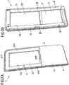
- Figs. 2A and 2B show a door leaf device 1 of a door 22 of the wagon 2 of Fig. 1 , wherein Fig. 2A shows a perspective view of the outside face 16 of the door leaf device 1 and Fig. 2B shows a perspective view of the inside face 17 of the door leaf device 1.
- the door leaf device 1 has a substantially flat overall shape and has a certain width and height which correspond to the horizontal and vertical extensions, respectively, of the door leaf device 1 being in use, i.e. when being installed in a wagon such as the wagon 2 according to Fig. 1 .
- outer door leaf layer Large parts of the outside face 16 of the door leaf device 1 are formed by an outer door leaf layer presently being formed as an outer door leaf shell 10, see Fig. 2A . Similarly, large parts of the inside face 17 of the door leaf device 1 are formed by an inner door leaf layer presently being formed as an inner door leaf shell 11, see Fig. 2B .
- the outer and inner door leaf shells 10, 11 each substantially extend over the height and the width of the door leaf device 1. Both the outer and inner door leaf shells 10, 11 each are formed in one piece from one piece of material. The production of the outer and inner door leaf shells 10, 11 will be described in more detail with reference to the following figures.
- a window 12 is provided in the door leaf device 1, comprising a window pane 121 extending over a window opening 120 provided by corresponding cutouts in the outer and inner door leaf shells 10, 11 having the same shape and being aligned to one another such as to allow for a clear view through the window 12.
- the window pane 121 is mounted on the door leaf device 1 on its outside face 16 and rests on corresponding abutment surfaces 101A-101D forming an rectangle on an upper part of the outer door leaf shell 10 and being recessed from adjacent parts of the outer door leaf shell 10 to an extent corresponding to the thickness of the window pane 121 to form an even outer surface 16.
- the window pane 121 may for example be adhered to the abutment surfaces 101A-101D.
- the door leaf device 1 is slightly bent such as to form a slightly convex overall shape as seen in direction on the outside face 10.
- the door leaf device 1 could alternatively also be formed flat or have a more complicated shape.
- the form of the door leaf device 1 may be adapted e.g. to the inner and/or outer shape of a wall of a wagon.
- seals 14 are arranged at lateral edges of the door leaf device 1 for providing a tight closure of the door in which the door leaf device 1 is or is to be mounted.
- Figs 2A and 2B show a simplified door leaf device 1 where various parts that such door leaf device 1 may comprise are not shown.
- a door leaf device 1 may comprise guiding devices, e.g. at upper and lower portions of the door leaf device, for a guiding of the door leaf device 1 when being displaced with respect to the wagon 2 between an opened and a closed position, connecting elements for a connection of the door leaf device 1 with other parts of the wagon 2, such as parts of a door drive mechanism, control elements for controlling an opening and/or closure of the door leaf device 1, signs etc.
- the outer and/or inner door leaf shells 10, 11 serve to define parts of the contour of the door leaf device 1 and may also at least partially form the surface of the door leaf device 1.
- the outer door leaf shell 10 substantially provides those parts of the surface on the outside face 16 of the door leaf device 1, which are not covered by the window pane 12.
- the inner door leaf shell 11 substantially provides those parts of the surface on the inside face 17 of the door leaf device 1, which are not covered by the window pane 12.
- the outer and inner door leaf shells 10, 11 substantially provide the opaque parts of the surfaces of the outside and inside faces 16, 17 of the door leaf device 1 (for the case that the outer and inner door leaf shells 10, 11 are not formed by a transparent material).
- outer and inner door leaf shells 10, 11 may be at least partially covered, e.g. by a cover layer, by a varnish, by a protection etc.
- the outer and/or inner door leaf shells 10, 11 may furthermore serve for or contribute to the structural stability of the door leaf device 1. In particular, depending on the material and its thickness, it may be possible to omit a heavy frame structure in the door leaf device.
- the door leaf device 1 may also be formed without any window 12, i.e., by opaque parts only.
- the window 12 may also be formed such as to extend over a larger part of the outside and inside faces 16, 17 of the door leaf device 1 such that the outer and inner door leaf shells form a shape similar to a frame for the window.
- the door leaf device 1 may also comprise more than one window, e.g. two windows or three windows.
- the window pane 121 (and window panes of the door leaf device 1 in general) may also be mounted on the window opening 120 on the inside face 17 of the door leaf device 1.
- the window pane 121 may also be inserted in slots provided on lateral side edges of the window opening 120 instead of being mounted on the abutment surfaces 101A-101D shown in Fig. 2A .
- the door leaf device 1 may be formed with a height of about 2100 mm, a width of about 810 mm and extend in a third direction vertical to the height and width directions by about 110 mm.
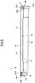
- Fig. 3 shows a section of the door leaf device 1 of Figs. 2A and 2B , being cut open along a plane A-A indicated in Fig. 2B , in a perspective view.
- sections of the outer door leaf shell 10 and the inner door leaf shell 11 are substantially arranged in parallel to each other and spaced apart from each other, such that an inner space 13 between the outer and inner door leaf shells 10, 11 is formed.
- the inner space 13 is substantially completely filled with a foam material, in particular with a rigid foam material, forming a core material in the form of a foam layer 15.
- the foam layer 15 is made of polyurethane (PU) foam, since such foam may be light, inexpensive and robust.
- the structural stability of the door leaf device 1 may be provided by the outer and inner door leaf shells 10, 11 in conjunction with the foam layer 15.
- the foam layer 15 may optionally be formed of different materials, e.g. different foam materials having different properties (e.g. specific weight, hardness, rigidity, etc.) or a foam material and another material.
- seals 14 are provided on the lateral edges of the door leaf device 1 .
- the seals 14 engage in recesses formed by cutouts 150A, 150B in the foam layer 15 arranged at gaps 18A, 18B between the lateral edges 102A, 102B of the outer door leaf shell 10 and lateral edges 111A, 111B of the inner door leaf shell 11.
- the seals 14 may be positively held in said recesses and/or adhered thereto.
- the lateral edges 102A, 102B, 111A, 111B of the outer and inner door leaf shells 10, 11 protrude at substantially vertical angles from the planes of the outer and inner door leaf shells 10, 11 forming the outside and inside faces 16, 17 of the door leaf device 1.
- the upper and lower edges of the outer and inner door leaf shells 10, 11 could be designed correspondingly. Therefore, no additional parts have to be mounted at the edges of the door leaf device 1.
- the foam layer 15 is made of polyurethane (PU) foam.
- the foam layer 15 may also comprise another rigid foam material as other synthetic foam or metal foam.
- the foam layer 15 may also comprise XPS foam, PVC foam and/or PET foam or any other suitable material.
- the foam layer 15 may in particular comprise rigid PU foam with a density of 30 to 300 kg/m 3 , and very particular rigid PU foam with a density of 50 to 100 kg/m 3 .
- the inner space 13 can also be partly filled with another suitable material having the required physical properties, in particular with respect to rigidity, acoustics and durability, e.g. glass fibers, a fiber-reinforced composite and/or a honeycomb material.
- the inner space 13 may also be filled with a combination of different foam materials or a combination of one or more foam materials with one or more other materials, e.g. a combination of PU foam with glass fibers, fiber-reinforced composites, honeycomb materials and/or rigid foam boards.
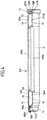
- Fig. 4 shows a section of the door leaf device 1 of Figs. 2A and 2B , being cut open along a plane B-B indicated in Fig. 2B , in a perspective view.
- the window opening 120 is formed by aligned cutouts 100A, 110A in the outer and inner door leaf shells 10, 11, respectively, as will be described in greater detail with reference to the following figures. Dashed lines indicate where material of the outer and inner door leaf shells 10, 11 has been removed for forming the window opening 120.
- FIG. 5A to 6B the production of the outer and inner door leaf shells 10, 11 will be described.
- Fig. 5A shows a perspective view of a forming tool 30 for the production of outer door leaf shells 10.
- Fig. 5B shows a perspective view of a forming tool 31 for the production of inner door leaf shells 11.
- the forming tools 30, 31 each comprise a base 300, 310 and a form block 301, 311 arranged on the respective base 300, 310.
- the form blocks 301, 311 each provide a positive form 305, 315 which correspond to the shape of the outer and inner door leaf shells 10, 11, respectively.
- the positive forms 305, 315 vertically project on an upper face of the form blocks 301, 311, wherein said upper faces serve as form areas 302, 312.
- the size of the form areas 302, 312 depend on the height and width of the door leaf device 1 and thus on the size of the outer and inner door leaf shells 10, 11, wherein the form areas 302, 312 are dimensioned such that a flat surface of the form areas 302, 312 each encompasses the positive forms 305, 315.
- the size of the form areas 302, 312 may be about 2250 mm in length and about 950 mm in width, wherein the lengths of the form areas 302, 312 result from the heights of the outer and inner door leaf shells 10, 11, respectively, being produced by the forming tools 30, 31 and the widths of the form areas 302, 312 result from their widths.
- the forming tools 30, 31 may serve for thermoforming or deep-drawing sheet material, e.g. sheets of a plastics material as plastic foils (or sheets of a polymer), sheet metal or others.
- a corresponding negative form may be used together with the positive forms 305, 315.
- forming tools 30, 31 are used for thermoforming with positive forms.
- the production of outer and inner door leaf shells 10, 11 will be described in more detail with reference to Figs. 6A and 6B , which show cross sections of the forming tools 30, 31 cut open at planes C-C and D-D, respectively.
- Fig. 6A shows in cross section various components of the forming tool 30 for forming outer door leaf shells 10.
- a heating mechanism comprising a plurality of heating elements 304 serving for heating the form block 301 and thereby for heating a thermoplastic material.
- the heating elements may be designed as electric conductors with a high electrical resistance heating by providing an electrical resistance to an electric current.
- a hot fluid such as hot water or steam may be conducted through the heating elements 304 which for this purpose can be formed as pipes, e.g. copper pipes.
- the thermoplastic sheet material When heated, the thermoplastic sheet material may be modified in its shape which is kept by the thermoplastic sheet material after subsequent cooling. The temperatures which are necessary to achieve a required flexibility depends on the specific material which is used as sheet material. Cooling may be effected passively by turning off the heating elements or actively by providing a cooling mechanism. For example, a cool fluid may be conducted through corresponding pipes.
- the heating elements 304 are formed as pipes, they could be also used as cooling elements.
- the forming tool 30 further comprises a plurality of vacuum chambers 303.
- a vacuum pump (not shown) for creating a negative pressure with respect to the surrounding air pressure is connected to the vacuum chambers 303 which are in fluid connection with a plurality of vacuum channels extending from the vacuum chambers 303 to the surface of the positive form 305 and possibly also to the form area 301 such that a negative pressure in the vacuum chambers 303 leads to a suction of a heated thermoplastic sheet material disposed on the forming tool 30 against the surface of the positive form 305 (and to the form area 301).
- the surrounding edges of the sheet material to be formed may be fixed or pressed against a frame with a suitable fixture (not shown). Therein, the sheet material may or may not be allowed to slide through the fixture.
- the fixture may also serve to provide a closed space between the positive form 305 and the sheet material such as to allow for the creation of a negative pressure.
- additional heating and/or cooling elements may be provided on the other side of the sheet material with respect to the heating elements 304 shown in Fig. 6A .
- the positive form 305 and the fixture may be displaceable with respect to one another.
- an outer door panel shell 10 may be produced by disposing a sheet material such as a plastics foil with a thickness of 2 mm or about 2 mm over the positive form 305, heating the sheet material such that it becomes flexible enough for forming, creating a negative pressure in the space between the sheet material and the positive form 305 (and optionally displace a fixture, e.g. a frame, holding the sheet material and the positive form 305 relatively towards one another) such that the sheet material lies against the positive form 305 and assumes the shape of the positive form 305, cooling the sheet material such that it becomes stiff and withdrawing the sheet material having the form of an outer door leaf shell 10 but still having a circumferential protrusion 103 which is removed in a later stage of the production.
- a sheet material such as a plastics foil with a thickness of 2 mm or about 2 mm
- heating the sheet material such that it becomes flexible enough for forming
- creating a negative pressure in the space between the sheet material and the positive form 305 and optionally displace a fixture,
- Fig. 6B shows the forming tool 31 for forming inner door leaf shells 11 in cross section.
- the forming tool 30 for forming outer door leaf shells 10 the forming tool 31 for forming inner door leaf shells 11 has heating elements 314 and vacuum chambers 313.
- the function of the forming tool 30 for forming inner door leaf shells 11 corresponds to the function of the forming tool 30 for forming outer door leaf shells 10 so that reference is made to the description referring to Fig. 6A above also regarding Fig. 6B .
- Fig. 7 shows a foaming tool 4 in cross section which is used for inserting a foam in the inner space 13 formed between the outer and inner door leaf shells 10, 11 after their corresponding arrangement as depicted.
- the foaming tool 4 comprises an upper tool part 40 and a lower tool part 41 which may be displaced with respect to one another so as to allow for disposing an outer and an inner door leaf shell 10, 11 in correspondingly shaped receptacles 403, 414 formed in tool blocks 404, 415 mounted on bases 400, 410 of each of the upper and lower tool parts 40, 41.
- a centering device 42 having opposing centering blocks 42A, 42B mounted on each of the upper and lower tool parts 40, 41 serve for a precise alignment of the upper and lower tool parts 40, 41.
- the centering blocks 42A, 42B may be arranged on various positions around the outer and inner door leaf shells 10, 11 located inside the foaming tool 4. Alternatively, one circumferential centering block 42A, 42B may be provided on each of the upper and lower tool parts 40, 41.
- a circumferential seal 413 is provided in the tool block 415 of the lower tool part 41 and serves for a tight closure of the foaming tool 4.
- seals may be provided in the upper tool part 40.
- the sheet material of the outer and inner door leaf shells 10, 11 may be urged against the receptacles 403, 414 by creating a negative pressure in vacuum chambers 401, 411 of the upper and lower tool parts 40, 41 connected with the receptacles 403, 414 by means of vacuum channels not shown in Fig. 7 .
- a foam material (and or other suitable materials for at least partially filling the inner space 13) may be introduced into the inner space 13.
- the material or part of the material may be disposed on one or both of the outer and inner door leaf shells 10, 11 before forming the inner space 13 by arranging the outer and inner door leaf shells 10, 11 against each other.
- Heating elements 402, 412 in the upper and lower tool parts 40, 41 may serve to activate or promote a foaming operation and/or harden or curing the foam material.
- the heating elements 402, 412 could be used for heating. Alternatively or selectively, they could also be used for cooling. Both heating and cooling could be effected e.g. electrically or by conducting a hot or cold fluid though the heating elements 402, 412.
- the heating elements 402, 412 can be formed as copper pipes.
- the foaming tool When the inner space 13 is filled with material, the foaming tool may again be opened for withdrawal of the door leaf device 1 thus formed.
- the foam material filled in the inner space 13 may serve to connect the outer and inner door leaf shells 10, 11 to one another.
- the outer an inner door leaf shells 10, 11 may also be connected to one another by other means of fastening.
- the outer and inner door leaf shells 10, 11 After filling the inner space 13 with material, the outer and inner door leaf shells 10, 11 still have circumferential protrusions 103, 112 and no cutouts for forming the window opening 120.
- the foaming tool may have a length of about 2300 mm, a width of about 1000 mm and a height of about 250 mm.
- the foaming tool may have a length of about 2300 mm, a width of about 1000 mm and a height of about 250 mm.
- also strongly differing sizes are possible and may e.g. depend on the size of the door leaf device 1 to be produced.
- Fig. 8 shows in a cross-sectional view a milling fixture 5 which is configured for fixing a door leaf device 1 on a fixture block 52 arranged on a base 50 thereof.
- a negative pressure may be applied for fixing the door leaf device 1 to the fixture block 52 by a mechanism similar to the vacuum mechanism of the forming tools 30, 31 and the foaming tool 4.
- a circumferential seal 51 serves for sealing the door leaf device 1 with the fixture block 52.
- the door leaf device 1 rests on the fixture block 52 with its outside face 16 formed by the outer door leaf shell 10.
- the circumferential protrusions 103, 112 of the outer and inner door leaf shells 10, 11 may be removed by milling.
- cutouts 150A, 150B for subsequent insertion of seals may be milled into the foam layer 15.
- cutouts 100A, 110A (not visible in Fig. 8 but shown in Fig. 4 ) for forming a window opening 120 in the door leaf device 1 may be milled or cut in the door leaf device 1.
- other parts of the door leaf device 1 may be worked on the milling fixture, e.g. other parts may be milled or cut, holes may be drilled and additional components may be mounted on the door leaf device 1.
- Figs. 9A and 9B show in perspective views another embodiment of a door leaf device 1'.
- the door leaf device 1' according to Figs. 9A and 9B as well as its production mostly corresponds to the door leaf device 1 according to Figs. 1 to 4 and the production explained with reference to Figs. 5A to 8 so that reference is made to the corresponding description hereinabove and only those details of the door leaf device 1' according to Figs. 9A and 9B and its production are described below in which it differs from the door leaf device 1 according to Figs. 1 to 4 .
- the door leaf device 1' comprises outer and inner door leaf layers in the form of outer and inner door leaf shells 10', 11' which are made of a transparent material.
- the transparency of the transparent material may be such as to allow to look through it.
- the transparent material may be a plastics material, a polymer material or glass, for example.
- the outer and inner door leaf shells 10, 11 of the door leaf device 1 according to Figs. 1 to 4 may be made of a transparent material, in contrast thereto, the outer and inner door leaf layers 10', 11' of Figs. 9A and 9B do not have cutouts for mounting a window pane.
- the outer and inner door leaf shells 10', 11' each comprise a window section 105, 114 which is recessed with respect to the surrounding material of the outer and inner door leaf layers 10', 11'.
- the window sections 105, 114 could of course also be flush with the adjacent surfaces or protrude therefrom.
- the window sections 105, 114 are aligned to one another such as to forms a window 12' of the door leaf device 1'.
- the outer and inner door leaf shells 10', 11' may form an inner space between each other also at the window sections 105, 114, it is preferred that this part of the inner space is not filled with a core material to maintain the transparency of the window 12'.
- the outer and inner door leaf shells 10', 11' could also contact each other at their window sections 105, 114, wherein then no inner space is formed there.
- the window sections 105, 114 may also be adhered or bonded to one another to increase stability and eventually to improve the optical properties of the window.
- the outer and inner door leaf shells 10', 11' each provide substantially the entire outer and inner faces 16, 17 of the door leaf device 1', respectively.
Landscapes
- Engineering & Computer Science (AREA)
- Mechanical Engineering (AREA)
- Securing Of Glass Panes Or The Like (AREA)
Claims (17)
- Türblatt, das zur Verwendung in einem Waggon (2) eines Massentransportfahrzeugs ausgebildet und vorgesehen ist, mit einer Außenseite (16), einer Innenseite (17), einer Höhe und einer Breite und mit einer äußeren Türblattschicht (10; 10'), die wenigstens teilweise die Außenseite (16) bildet, und einer inneren Türblattschicht (11; 11'), die wenigstens teilweise die Innenseite (17) bildet, wobei die äußere und die innere Türblattschicht (10, 11; 10', 11') so zueinander angeordnet sind, dass sie dazwischen einen Innenraum (13) bilden,
dadurch gekennzeichnet, dass
sich mindestens eine von der äußeren und der inneren Türblattschicht (10, 11; 10', 11') im Wesentlichen über die gesamte Höhe und/oder die gesamte Breite des Türblatts (1; 1') erstreckt und einstückig ausgebildet ist, wobei mindestens die eine von der äußeren und der inneren Türblattschicht (10, 11; 10', 11') durch Tiefziehen oder Thermoformen eines flächigen Polymermaterials hergestellt ist. - Türblatt nach Anspruch 1, dadurch gekennzeichnet, dass sich sowohl die äußere Türblattschicht (10, 10') als auch die innere Türblattschicht (11, 11') jeweils im Wesentlichen über die Höhe und/oder die Breite des Türblatts (1; 1') erstrecken und jeweils einstückig ausgebildet sind.
- Türblatt nach Anspruch 1 oder 2, dadurch gekennzeichnet, dass der Innenraum (13) zwischen der äußeren und der inneren Türblattschicht (10, 11; 10', 11') wenigstens teilweise mit einem Kernmaterial (15) gefüllt ist.
- Türblatt nach Anspruch 3, dadurch gekennzeichnet, dass das Kernmaterial (15) mindestens eines von einem Schaummaterial, Polyurethanschaum, Melaminharzschaum, Glasfaser, einem faserverstärkten Verbundstoff, einem Wabenmaterial und einer Hartschaumplatte umfasst.
- Türblatt nach Anspruch 4, dadurch gekennzeichnet, dass das Kernmaterial (15) ein erstes Schaummaterial mit einer ersten Härte und ein zweites Schaummaterial mit einer zweiten Härte umfasst, wobei die erste Härte und die zweite Härte voneinander verschieden sind.
- Türblatt nach einem der Ansprüche 3 bis 5, dadurch gekennzeichnet, dass die äußere und die innere Türblattschicht (10, 11) und/oder das Kernmaterial (15) aus einem flammhemmenden, nicht-metallischen Material bestehen.
- Türblatt nach einem der vorhergehenden Ansprüche, gekennzeichnet durch ein Fenster (12), das durch Ausschnitte (100A, 110A) in der äußeren und der inneren Türblattschicht (10, 11) gebildet ist.
- Türblatt nach einem der vorhergehenden Ansprüche, dadurch gekennzeichnet, dass mindestens eine von der äußeren und der inneren Türblattschicht (10', 11') ein transparentes Material umfasst, wobei mindestens ein Abschnitt (105, 114) des transparenten Materials ein Fenster (12') des Türblatts (1') bildet.
- Türblatt nach einem der vorhergehenden Ansprüche, dadurch gekennzeichnet, das mindestens die eine von der äußeren und der inneren Türblattschicht (10, 11; 10', 11') mindestens einen Kantenabschnitt (102A, 102B, 111A, 111B) von seitlichen, oberen und unteren Kanten des Türblatts (1; 1') bereitstellt.
- Türblatt nach einem der vorhergehenden Ansprüche, dadurch gekennzeichnet, dass mindestens eine von der äußeren und der inneren Türblattschicht (10, 11; 10', 11') eine Innenfläche (104, 113) umfasst, die wenigstens teilweise dem Innenraum (13) zugewandt ist und wenigstens teilweise mit einem Polymermaterial, einem Harz, Epoxid und/oder einem Fasermaterial wie zum Beispiel Glasfaser versehen ist.
- Türblatt nach einem der vorhergehenden Ansprüche, dadurch gekennzeichnet, dass mindestens eine von der äußeren und der inneren Türblattschicht (10, 11; 10', 11') mindestens einen Teilabschnitt der Außenseite des Türblatts (1) bildet, wobei insbesondere mindestens eine von der äußeren und der inneren Türblattschicht (10, 11; 10', 11') eine Oberflächenstruktur bildet und/oder eine außen sichtbare Farbe mindestens eines Teilabschnitts der Außenseite des Türblatts (1) bereitstellt.
- Türblatt nach einem der vorhergehenden Ansprüche, dadurch gekennzeichnet, dass mindestens eine von der äußeren und der inneren Türblattschicht (10, 11; 10', 11') durchgefärbt ist und/oder aus einem voll durchgefärbten Material besteht.
- Waggon (2), mit mindestens einem Türblatt (1; 1') nach einem der Ansprüche 1 bis 12.
- Verfahren zur Herstellung eines Türblatts, das zur Verwendung in einem Waggon (2) eines Massentransportfahrzeugs ausgebildet und vorgesehen ist und eine Außenseite (16), eine Innenseite (17), eine Höhe und eine Breite besitzt, wobei das Verfahren die folgenden Schritte umfasst:- Bereitstellen einer äußeren Türblattschicht (10; 10'), um wenigstens teilweise die Außenseite (16) zu bilden, und einer inneren Türblattschicht (11; 11'), um wenigstens teilweise die Innenseite (17) zu bilden, und- Anordnen der äußeren und der inneren Türblattschicht (10, 11; 10', 11') so zueinander, dass dazwischen ein Innenraum (13) gebildet wird,gekennzeichnet durch den vorhergehenden Schritt, bei dem:- wenigstens eine von der äußeren und der inneren Türblattschicht (10, 11; 10', 11') einstückig ausgebildet wird, sodass sie sich im Wesentlichen über die gesamte Höhe und/oder die gesamte Breite des Türblatts (1; 1') erstreckt, wobei wenigstens die eine von der äußeren und der inneren Türblattschicht (10, 11; 10', 11') durch Tiefziehen oder Thermoformen eines flächigen Polymermaterials einstückig ausgebildet wird.
- Verfahren nach Anspruch 14, gekennzeichnet durch den anschließenden Schritt des Einbringens eines Schaummaterials (15) in den Innenraum (13) zwischen der äußeren und der inneren Türblattschicht (10, 11; 10', 11').
- Verfahren nach Anspruch 14 oder 15, gekennzeichnet durch den anschließenden Schritt des Entfernens von Material von mindestens einer von der äußeren und der inneren Türblattschicht (10, 11; 10', 11') durch mindestens einen der Vorgänge Schneiden, Fräsen und Bohren.
- Verfahren nach Anspruch 16, gekennzeichnet durch das Anordnen einer Fensterscheibe (121) an einer durch den Schritt des Entfernens von Material durch Ausschnitte (100A, 110A) in der äußeren und der inneren Türblattschicht (10, 11; 10', 11') gebildeten Fensteröffnung (120).
Priority Applications (1)
| Application Number | Priority Date | Filing Date | Title |
|---|---|---|---|
| EP14183964.7A EP2993103B1 (de) | 2014-09-08 | 2014-09-08 | Türblatt für Massentransportfahrzeuge |
Applications Claiming Priority (1)
| Application Number | Priority Date | Filing Date | Title |
|---|---|---|---|
| EP14183964.7A EP2993103B1 (de) | 2014-09-08 | 2014-09-08 | Türblatt für Massentransportfahrzeuge |
Publications (2)
| Publication Number | Publication Date |
|---|---|
| EP2993103A1 EP2993103A1 (de) | 2016-03-09 |
| EP2993103B1 true EP2993103B1 (de) | 2019-10-30 |
Family
ID=51494146
Family Applications (1)
| Application Number | Title | Priority Date | Filing Date |
|---|---|---|---|
| EP14183964.7A Active EP2993103B1 (de) | 2014-09-08 | 2014-09-08 | Türblatt für Massentransportfahrzeuge |
Country Status (1)
| Country | Link |
|---|---|
| EP (1) | EP2993103B1 (de) |
Families Citing this family (7)
| Publication number | Priority date | Publication date | Assignee | Title |
|---|---|---|---|---|
| DE102016108637B3 (de) * | 2016-05-10 | 2017-10-12 | Knorr-Bremse Gesellschaft Mit Beschränkter Haftung | Schiebetüre für ein Schienenfahrzeug |
| CN107985325A (zh) * | 2016-11-10 | 2018-05-04 | 北京博得交通设备有限公司 | 内藏式微动塞拉门 |
| AT522145B1 (de) * | 2019-02-14 | 2021-05-15 | Eh Holding Gmbh | Wagenkastenelement für einen Zugswaggon |
| DE102019004311A1 (de) * | 2019-06-19 | 2021-01-07 | Knorr-Bremse Gesellschaft Mit Beschränkter Haftung | Türflügel einer Türvorrichtung eines Fahrzeugs |
| DE202020101702U1 (de) * | 2020-03-30 | 2021-07-01 | Gebr. Bode Gmbh & Co. Kg | Druckertüchtigtes zweiflügeliges Türsystem |
| DE102020108784A1 (de) * | 2020-03-30 | 2021-09-30 | Gebr. Bode Gmbh & Co. Kg | Druckdichtes zweiflügeliges Türsystem |
| DE102022132224A1 (de) * | 2022-12-05 | 2024-06-06 | Knorr-Bremse Gesellschaft Mit Beschränkter Haftung | Türblatt für ein schienenfahrzeug und verfahren zum herstellen eines türblattes |
Family Cites Families (4)
| Publication number | Priority date | Publication date | Assignee | Title |
|---|---|---|---|---|
| AT501745B1 (de) * | 2005-08-01 | 2006-11-15 | Knorr Bremse Gmbh | Türblatt |
| US20070245672A1 (en) * | 2006-03-31 | 2007-10-25 | Durakon Industries, Inc. | Composite plug door for use on railcars |
| DE102007062528B4 (de) * | 2007-12-20 | 2014-09-18 | Bombardier Transportation Gmbh | Türflügel für ein Fahrzeug |
| DE102009043723B4 (de) * | 2009-10-01 | 2013-06-06 | Bombardier Transportation Gmbh | Türanordnung für ein Schienenfahrzeug |
-
2014
- 2014-09-08 EP EP14183964.7A patent/EP2993103B1/de active Active
Non-Patent Citations (1)
| Title |
|---|
| None * |
Also Published As
| Publication number | Publication date |
|---|---|
| EP2993103A1 (de) | 2016-03-09 |
Similar Documents
| Publication | Publication Date | Title |
|---|---|---|
| EP2993103B1 (de) | Türblatt für Massentransportfahrzeuge | |
| EP2870066B1 (de) | Flugzeuginnenraumpaneel mit akustischen materialien | |
| CN101173589B (zh) | 场所间隔元件 | |
| US10773485B2 (en) | Composite glass pane with a mounting hole | |
| EP3669041B1 (de) | Türen mit verglaster einheit und verfahren zu ihrer herstellung | |
| CN108909415B (zh) | 具有承载件且带有防侵入件的门组件 | |
| US20110272974A1 (en) | Whole glass roof for a motor vehicle | |
| CN110461634B (zh) | 用于车门的玻璃装置、门、机动车及其制造方法和密封装置 | |
| US8052088B2 (en) | Injection-molded window panel and related methods | |
| EP3571077B1 (de) | Dachrahmen aus verbundwerkstoff und herstellungsverfahren derselben | |
| CN104768826A (zh) | 用于车辆、尤其是轨道车辆的门扇 | |
| RU2744088C2 (ru) | Сдвигаемое многослойное остекление с внутренним выступом | |
| CA2936857A1 (en) | Lightweight structural joiner | |
| MXPA04010200A (es) | Puerta de vehiculo y metodo para la produccion de la misma. | |
| US20150259971A1 (en) | Door of platform door apparatus | |
| KR102071428B1 (ko) | 페인 및 적어도 하나의 리프팅 레일을 포함하는 장치, 그의 제조 방법 및 그의 용도 | |
| US20180282129A1 (en) | Planar elevator car element for an elevator installation | |
| CN114144299A (zh) | 复合材料车辆部件构造 | |
| US20220146232A1 (en) | Ballistic glass and associated methods and assemblies | |
| DK164094B (da) | Let konstruktionselement, isaer til vogndoere | |
| US20140065330A1 (en) | Glazing for a rail vehicle | |
| US11867942B1 (en) | Encapsulated illuminated automotive glazing and method of producing thereof | |
| KR200457724Y1 (ko) | 특수차량용 사이드 윈도우 | |
| KR200462722Y1 (ko) | 특수차량용 사이드 윈도우 | |
| CZ35901U1 (cs) | Sprchový box, zejména pro obytné automobily |
Legal Events
| Date | Code | Title | Description |
|---|---|---|---|
| PUAI | Public reference made under article 153(3) epc to a published international application that has entered the european phase |
Free format text: ORIGINAL CODE: 0009012 |
|
| AK | Designated contracting states |
Kind code of ref document: A1 Designated state(s): AL AT BE BG CH CY CZ DE DK EE ES FI FR GB GR HR HU IE IS IT LI LT LU LV MC MK MT NL NO PL PT RO RS SE SI SK SM TR |
|
| AX | Request for extension of the european patent |
Extension state: BA ME |
|
| 17P | Request for examination filed |
Effective date: 20160909 |
|
| RBV | Designated contracting states (corrected) |
Designated state(s): AL AT BE BG CH CY CZ DE DK EE ES FI FR GB GR HR HU IE IS IT LI LT LU LV MC MK MT NL NO PL PT RO RS SE SI SK SM TR |
|
| STAA | Information on the status of an ep patent application or granted ep patent |
Free format text: STATUS: EXAMINATION IS IN PROGRESS |
|
| 17Q | First examination report despatched |
Effective date: 20181011 |
|
| GRAP | Despatch of communication of intention to grant a patent |
Free format text: ORIGINAL CODE: EPIDOSNIGR1 |
|
| STAA | Information on the status of an ep patent application or granted ep patent |
Free format text: STATUS: GRANT OF PATENT IS INTENDED |
|
| INTG | Intention to grant announced |
Effective date: 20190404 |
|
| GRAS | Grant fee paid |
Free format text: ORIGINAL CODE: EPIDOSNIGR3 |
|
| GRAA | (expected) grant |
Free format text: ORIGINAL CODE: 0009210 |
|
| STAA | Information on the status of an ep patent application or granted ep patent |
Free format text: STATUS: THE PATENT HAS BEEN GRANTED |
|
| AK | Designated contracting states |
Kind code of ref document: B1 Designated state(s): AL AT BE BG CH CY CZ DE DK EE ES FI FR GB GR HR HU IE IS IT LI LT LU LV MC MK MT NL NO PL PT RO RS SE SI SK SM TR |
|
| REG | Reference to a national code |
Ref country code: GB Ref legal event code: FG4D |
|
| REG | Reference to a national code |
Ref country code: CH Ref legal event code: EP |
|
| REG | Reference to a national code |
Ref country code: AT Ref legal event code: REF Ref document number: 1195823 Country of ref document: AT Kind code of ref document: T Effective date: 20191115 |
|
| REG | Reference to a national code |
Ref country code: DE Ref legal event code: R096 Ref document number: 602014055853 Country of ref document: DE |
|
| REG | Reference to a national code |
Ref country code: IE Ref legal event code: FG4D |
|
| REG | Reference to a national code |
Ref country code: LT Ref legal event code: MG4D |
|
| PG25 | Lapsed in a contracting state [announced via postgrant information from national office to epo] |
Ref country code: GR Free format text: LAPSE BECAUSE OF FAILURE TO SUBMIT A TRANSLATION OF THE DESCRIPTION OR TO PAY THE FEE WITHIN THE PRESCRIBED TIME-LIMIT Effective date: 20200131 Ref country code: LT Free format text: LAPSE BECAUSE OF FAILURE TO SUBMIT A TRANSLATION OF THE DESCRIPTION OR TO PAY THE FEE WITHIN THE PRESCRIBED TIME-LIMIT Effective date: 20191030 Ref country code: NO Free format text: LAPSE BECAUSE OF FAILURE TO SUBMIT A TRANSLATION OF THE DESCRIPTION OR TO PAY THE FEE WITHIN THE PRESCRIBED TIME-LIMIT Effective date: 20200130 Ref country code: BG Free format text: LAPSE BECAUSE OF FAILURE TO SUBMIT A TRANSLATION OF THE DESCRIPTION OR TO PAY THE FEE WITHIN THE PRESCRIBED TIME-LIMIT Effective date: 20200130 Ref country code: NL Free format text: LAPSE BECAUSE OF FAILURE TO SUBMIT A TRANSLATION OF THE DESCRIPTION OR TO PAY THE FEE WITHIN THE PRESCRIBED TIME-LIMIT Effective date: 20191030 Ref country code: SE Free format text: LAPSE BECAUSE OF FAILURE TO SUBMIT A TRANSLATION OF THE DESCRIPTION OR TO PAY THE FEE WITHIN THE PRESCRIBED TIME-LIMIT Effective date: 20191030 Ref country code: LV Free format text: LAPSE BECAUSE OF FAILURE TO SUBMIT A TRANSLATION OF THE DESCRIPTION OR TO PAY THE FEE WITHIN THE PRESCRIBED TIME-LIMIT Effective date: 20191030 Ref country code: ES Free format text: LAPSE BECAUSE OF FAILURE TO SUBMIT A TRANSLATION OF THE DESCRIPTION OR TO PAY THE FEE WITHIN THE PRESCRIBED TIME-LIMIT Effective date: 20191030 Ref country code: PL Free format text: LAPSE BECAUSE OF FAILURE TO SUBMIT A TRANSLATION OF THE DESCRIPTION OR TO PAY THE FEE WITHIN THE PRESCRIBED TIME-LIMIT Effective date: 20191030 Ref country code: FI Free format text: LAPSE BECAUSE OF FAILURE TO SUBMIT A TRANSLATION OF THE DESCRIPTION OR TO PAY THE FEE WITHIN THE PRESCRIBED TIME-LIMIT Effective date: 20191030 Ref country code: PT Free format text: LAPSE BECAUSE OF FAILURE TO SUBMIT A TRANSLATION OF THE DESCRIPTION OR TO PAY THE FEE WITHIN THE PRESCRIBED TIME-LIMIT Effective date: 20200302 |
|
| REG | Reference to a national code |
Ref country code: NL Ref legal event code: MP Effective date: 20191030 |
|
| PG25 | Lapsed in a contracting state [announced via postgrant information from national office to epo] |
Ref country code: IS Free format text: LAPSE BECAUSE OF FAILURE TO SUBMIT A TRANSLATION OF THE DESCRIPTION OR TO PAY THE FEE WITHIN THE PRESCRIBED TIME-LIMIT Effective date: 20200229 Ref country code: RS Free format text: LAPSE BECAUSE OF FAILURE TO SUBMIT A TRANSLATION OF THE DESCRIPTION OR TO PAY THE FEE WITHIN THE PRESCRIBED TIME-LIMIT Effective date: 20191030 Ref country code: HR Free format text: LAPSE BECAUSE OF FAILURE TO SUBMIT A TRANSLATION OF THE DESCRIPTION OR TO PAY THE FEE WITHIN THE PRESCRIBED TIME-LIMIT Effective date: 20191030 |
|
| PG25 | Lapsed in a contracting state [announced via postgrant information from national office to epo] |
Ref country code: AL Free format text: LAPSE BECAUSE OF FAILURE TO SUBMIT A TRANSLATION OF THE DESCRIPTION OR TO PAY THE FEE WITHIN THE PRESCRIBED TIME-LIMIT Effective date: 20191030 |
|
| PG25 | Lapsed in a contracting state [announced via postgrant information from national office to epo] |
Ref country code: DK Free format text: LAPSE BECAUSE OF FAILURE TO SUBMIT A TRANSLATION OF THE DESCRIPTION OR TO PAY THE FEE WITHIN THE PRESCRIBED TIME-LIMIT Effective date: 20191030 Ref country code: EE Free format text: LAPSE BECAUSE OF FAILURE TO SUBMIT A TRANSLATION OF THE DESCRIPTION OR TO PAY THE FEE WITHIN THE PRESCRIBED TIME-LIMIT Effective date: 20191030 Ref country code: CZ Free format text: LAPSE BECAUSE OF FAILURE TO SUBMIT A TRANSLATION OF THE DESCRIPTION OR TO PAY THE FEE WITHIN THE PRESCRIBED TIME-LIMIT Effective date: 20191030 Ref country code: RO Free format text: LAPSE BECAUSE OF FAILURE TO SUBMIT A TRANSLATION OF THE DESCRIPTION OR TO PAY THE FEE WITHIN THE PRESCRIBED TIME-LIMIT Effective date: 20191030 |
|
| REG | Reference to a national code |
Ref country code: DE Ref legal event code: R097 Ref document number: 602014055853 Country of ref document: DE |
|
| REG | Reference to a national code |
Ref country code: AT Ref legal event code: MK05 Ref document number: 1195823 Country of ref document: AT Kind code of ref document: T Effective date: 20191030 |
|
| PG25 | Lapsed in a contracting state [announced via postgrant information from national office to epo] |
Ref country code: SK Free format text: LAPSE BECAUSE OF FAILURE TO SUBMIT A TRANSLATION OF THE DESCRIPTION OR TO PAY THE FEE WITHIN THE PRESCRIBED TIME-LIMIT Effective date: 20191030 Ref country code: IT Free format text: LAPSE BECAUSE OF FAILURE TO SUBMIT A TRANSLATION OF THE DESCRIPTION OR TO PAY THE FEE WITHIN THE PRESCRIBED TIME-LIMIT Effective date: 20191030 Ref country code: SM Free format text: LAPSE BECAUSE OF FAILURE TO SUBMIT A TRANSLATION OF THE DESCRIPTION OR TO PAY THE FEE WITHIN THE PRESCRIBED TIME-LIMIT Effective date: 20191030 |
|
| PLBE | No opposition filed within time limit |
Free format text: ORIGINAL CODE: 0009261 |
|
| STAA | Information on the status of an ep patent application or granted ep patent |
Free format text: STATUS: NO OPPOSITION FILED WITHIN TIME LIMIT |
|
| 26N | No opposition filed |
Effective date: 20200731 |
|
| PGFP | Annual fee paid to national office [announced via postgrant information from national office to epo] |
Ref country code: IE Payment date: 20200918 Year of fee payment: 7 Ref country code: MC Payment date: 20200825 Year of fee payment: 7 Ref country code: LU Payment date: 20200907 Year of fee payment: 7 |
|
| PG25 | Lapsed in a contracting state [announced via postgrant information from national office to epo] |
Ref country code: AT Free format text: LAPSE BECAUSE OF FAILURE TO SUBMIT A TRANSLATION OF THE DESCRIPTION OR TO PAY THE FEE WITHIN THE PRESCRIBED TIME-LIMIT Effective date: 20191030 Ref country code: SI Free format text: LAPSE BECAUSE OF FAILURE TO SUBMIT A TRANSLATION OF THE DESCRIPTION OR TO PAY THE FEE WITHIN THE PRESCRIBED TIME-LIMIT Effective date: 20191030 |
|
| PG25 | Lapsed in a contracting state [announced via postgrant information from national office to epo] |
Ref country code: TR Free format text: LAPSE BECAUSE OF FAILURE TO SUBMIT A TRANSLATION OF THE DESCRIPTION OR TO PAY THE FEE WITHIN THE PRESCRIBED TIME-LIMIT Effective date: 20191030 Ref country code: MT Free format text: LAPSE BECAUSE OF FAILURE TO SUBMIT A TRANSLATION OF THE DESCRIPTION OR TO PAY THE FEE WITHIN THE PRESCRIBED TIME-LIMIT Effective date: 20191030 Ref country code: MC Free format text: LAPSE BECAUSE OF NON-PAYMENT OF DUE FEES Effective date: 20210930 Ref country code: CY Free format text: LAPSE BECAUSE OF FAILURE TO SUBMIT A TRANSLATION OF THE DESCRIPTION OR TO PAY THE FEE WITHIN THE PRESCRIBED TIME-LIMIT Effective date: 20191030 |
|
| PG25 | Lapsed in a contracting state [announced via postgrant information from national office to epo] |
Ref country code: MK Free format text: LAPSE BECAUSE OF FAILURE TO SUBMIT A TRANSLATION OF THE DESCRIPTION OR TO PAY THE FEE WITHIN THE PRESCRIBED TIME-LIMIT Effective date: 20191030 |
|
| PG25 | Lapsed in a contracting state [announced via postgrant information from national office to epo] |
Ref country code: LU Free format text: LAPSE BECAUSE OF NON-PAYMENT OF DUE FEES Effective date: 20210908 Ref country code: IE Free format text: LAPSE BECAUSE OF NON-PAYMENT OF DUE FEES Effective date: 20210908 |
|
| P01 | Opt-out of the competence of the unified patent court (upc) registered |
Effective date: 20230530 |
|
| REG | Reference to a national code |
Ref country code: CH Ref legal event code: U11 Free format text: ST27 STATUS EVENT CODE: U-0-0-U10-U11 (AS PROVIDED BY THE NATIONAL OFFICE) Effective date: 20251001 |
|
| PGFP | Annual fee paid to national office [announced via postgrant information from national office to epo] |
Ref country code: DE Payment date: 20250819 Year of fee payment: 12 |
|
| PGFP | Annual fee paid to national office [announced via postgrant information from national office to epo] |
Ref country code: BE Payment date: 20250819 Year of fee payment: 12 Ref country code: GB Payment date: 20250821 Year of fee payment: 12 |
|
| PGFP | Annual fee paid to national office [announced via postgrant information from national office to epo] |
Ref country code: FR Payment date: 20250818 Year of fee payment: 12 |
|
| PGFP | Annual fee paid to national office [announced via postgrant information from national office to epo] |
Ref country code: CH Payment date: 20251001 Year of fee payment: 12 |