EP2993149A1 - Druckmedienentladungseinheit, druckmedienführungsanordnung, blattstapelvorrichtung, bildwiedergabevorrichtung, und verfahren zur modifizierung einer bildwiedergabevorrichtung - Google Patents
Druckmedienentladungseinheit, druckmedienführungsanordnung, blattstapelvorrichtung, bildwiedergabevorrichtung, und verfahren zur modifizierung einer bildwiedergabevorrichtung Download PDFInfo
- Publication number
- EP2993149A1 EP2993149A1 EP15176944.5A EP15176944A EP2993149A1 EP 2993149 A1 EP2993149 A1 EP 2993149A1 EP 15176944 A EP15176944 A EP 15176944A EP 2993149 A1 EP2993149 A1 EP 2993149A1
- Authority
- EP
- European Patent Office
- Prior art keywords
- print media
- discharge unit
- transport path
- unit according
- reproduction apparatus
- Prior art date
- Legal status (The legal status is an assumption and is not a legal conclusion. Google has not performed a legal analysis and makes no representation as to the accuracy of the status listed.)
- Granted
Links
- 238000000034 method Methods 0.000 title claims description 5
- 239000000463 material Substances 0.000 claims description 6
- 239000004033 plastic Substances 0.000 claims description 3
- 239000002245 particle Substances 0.000 description 12
- 239000002184 metal Substances 0.000 description 10
- 238000011144 upstream manufacturing Methods 0.000 description 5
- 230000005684 electric field Effects 0.000 description 4
- 230000007547 defect Effects 0.000 description 3
- 239000000835 fiber Substances 0.000 description 3
- 238000003384 imaging method Methods 0.000 description 3
- 230000003068 static effect Effects 0.000 description 3
- 210000005069 ears Anatomy 0.000 description 2
- 230000005611 electricity Effects 0.000 description 2
- 238000012986 modification Methods 0.000 description 2
- 230000004048 modification Effects 0.000 description 2
- 229920000049 Carbon (fiber) Polymers 0.000 description 1
- 239000000853 adhesive Substances 0.000 description 1
- 230000001070 adhesive effect Effects 0.000 description 1
- 239000004917 carbon fiber Substances 0.000 description 1
- 239000003086 colorant Substances 0.000 description 1
- 230000007423 decrease Effects 0.000 description 1
- 230000001419 dependent effect Effects 0.000 description 1
- 238000011143 downstream manufacturing Methods 0.000 description 1
- 238000010438 heat treatment Methods 0.000 description 1
- VNWKTOKETHGBQD-UHFFFAOYSA-N methane Chemical compound C VNWKTOKETHGBQD-UHFFFAOYSA-N 0.000 description 1
- 239000000203 mixture Substances 0.000 description 1
- 238000012805 post-processing Methods 0.000 description 1
- 239000011347 resin Substances 0.000 description 1
- 229920005989 resin Polymers 0.000 description 1
Images


Classifications
-
- B—PERFORMING OPERATIONS; TRANSPORTING
- B65—CONVEYING; PACKING; STORING; HANDLING THIN OR FILAMENTARY MATERIAL
- B65H—HANDLING THIN OR FILAMENTARY MATERIAL, e.g. SHEETS, WEBS, CABLES
- B65H29/00—Delivering or advancing articles from machines; Advancing articles to or into piles
- B65H29/52—Stationary guides or smoothers
-
- G—PHYSICS
- G03—PHOTOGRAPHY; CINEMATOGRAPHY; ANALOGOUS TECHNIQUES USING WAVES OTHER THAN OPTICAL WAVES; ELECTROGRAPHY; HOLOGRAPHY
- G03G—ELECTROGRAPHY; ELECTROPHOTOGRAPHY; MAGNETOGRAPHY
- G03G15/00—Apparatus for electrographic processes using a charge pattern
- G03G15/65—Apparatus which relate to the handling of copy material
- G03G15/6555—Handling of sheet copy material taking place in a specific part of the copy material feeding path
- G03G15/6573—Feeding path after the fixing point and up to the discharge tray or the finisher, e.g. special treatment of copy material to compensate for effects from the fixing
-
- B—PERFORMING OPERATIONS; TRANSPORTING
- B65—CONVEYING; PACKING; STORING; HANDLING THIN OR FILAMENTARY MATERIAL
- B65H—HANDLING THIN OR FILAMENTARY MATERIAL, e.g. SHEETS, WEBS, CABLES
- B65H2301/00—Handling processes for sheets or webs
- B65H2301/50—Auxiliary process performed during handling process
- B65H2301/51—Modifying a characteristic of handled material
- B65H2301/513—Modifying electric properties
- B65H2301/5133—Removing electrostatic charge
-
- B—PERFORMING OPERATIONS; TRANSPORTING
- B65—CONVEYING; PACKING; STORING; HANDLING THIN OR FILAMENTARY MATERIAL
- B65H—HANDLING THIN OR FILAMENTARY MATERIAL, e.g. SHEETS, WEBS, CABLES
- B65H2401/00—Materials used for the handling apparatus or parts thereof; Properties thereof
- B65H2401/20—Physical properties, e.g. lubricity
- B65H2401/21—Electrical or magnetic properties, e.g. conductivity or resistance
-
- B—PERFORMING OPERATIONS; TRANSPORTING
- B65—CONVEYING; PACKING; STORING; HANDLING THIN OR FILAMENTARY MATERIAL
- B65H—HANDLING THIN OR FILAMENTARY MATERIAL, e.g. SHEETS, WEBS, CABLES
- B65H2404/00—Parts for transporting or guiding the handled material
- B65H2404/50—Surface of the elements in contact with the forwarded or guided material
- B65H2404/51—Cross section, i.e. section perpendicular to the direction of displacement
- B65H2404/513—Cross section, i.e. section perpendicular to the direction of displacement with limited number of active areas
-
- B—PERFORMING OPERATIONS; TRANSPORTING
- B65—CONVEYING; PACKING; STORING; HANDLING THIN OR FILAMENTARY MATERIAL
- B65H—HANDLING THIN OR FILAMENTARY MATERIAL, e.g. SHEETS, WEBS, CABLES
- B65H2404/00—Parts for transporting or guiding the handled material
- B65H2404/50—Surface of the elements in contact with the forwarded or guided material
- B65H2404/53—Surface of the elements in contact with the forwarded or guided material with particular mechanical, physical properties
- B65H2404/533—Surface of the elements in contact with the forwarded or guided material with particular mechanical, physical properties with particular electric properties, e.g. dielectric material
-
- B—PERFORMING OPERATIONS; TRANSPORTING
- B65—CONVEYING; PACKING; STORING; HANDLING THIN OR FILAMENTARY MATERIAL
- B65H—HANDLING THIN OR FILAMENTARY MATERIAL, e.g. SHEETS, WEBS, CABLES
- B65H2404/00—Parts for transporting or guiding the handled material
- B65H2404/50—Surface of the elements in contact with the forwarded or guided material
- B65H2404/56—Flexible surface
- B65H2404/561—Bristles, brushes
-
- B—PERFORMING OPERATIONS; TRANSPORTING
- B65—CONVEYING; PACKING; STORING; HANDLING THIN OR FILAMENTARY MATERIAL
- B65H—HANDLING THIN OR FILAMENTARY MATERIAL, e.g. SHEETS, WEBS, CABLES
- B65H2404/00—Parts for transporting or guiding the handled material
- B65H2404/60—Other elements in face contact with handled material
- B65H2404/61—Longitudinally-extending strips, tubes, plates, or wires
- B65H2404/611—Longitudinally-extending strips, tubes, plates, or wires arranged to form a channel
-
- B—PERFORMING OPERATIONS; TRANSPORTING
- B65—CONVEYING; PACKING; STORING; HANDLING THIN OR FILAMENTARY MATERIAL
- B65H—HANDLING THIN OR FILAMENTARY MATERIAL, e.g. SHEETS, WEBS, CABLES
- B65H2801/00—Application field
- B65H2801/24—Post -processing devices
- B65H2801/27—Devices located downstream of office-type machines
-
- G—PHYSICS
- G03—PHOTOGRAPHY; CINEMATOGRAPHY; ANALOGOUS TECHNIQUES USING WAVES OTHER THAN OPTICAL WAVES; ELECTROGRAPHY; HOLOGRAPHY
- G03G—ELECTROGRAPHY; ELECTROPHOTOGRAPHY; MAGNETOGRAPHY
- G03G15/00—Apparatus for electrographic processes using a charge pattern
- G03G15/65—Apparatus which relate to the handling of copy material
- G03G15/6538—Devices for collating sheet copy material, e.g. sorters, control, copies in staples form
-
- G—PHYSICS
- G03—PHOTOGRAPHY; CINEMATOGRAPHY; ANALOGOUS TECHNIQUES USING WAVES OTHER THAN OPTICAL WAVES; ELECTROGRAPHY; HOLOGRAPHY
- G03G—ELECTROGRAPHY; ELECTROPHOTOGRAPHY; MAGNETOGRAPHY
- G03G2215/00—Apparatus for electrophotographic processes
- G03G2215/00362—Apparatus for electrophotographic processes relating to the copy medium handling
- G03G2215/00535—Stable handling of copy medium
- G03G2215/00679—Conveying means details, e.g. roller
- G03G2215/00683—Chemical properties
Definitions
- the invention pertains to a print media discharge unit, comprising a print media transport path along which in operation a sheet of print media is transported in a transport direction, the print media transport path is defined by a first electrically isolating print media guide and a second electrically isolating print media guide.
- the invention also relates to a print media guidance assembly, a sheet stacking device and an image reproduction apparatus comprising such a print media discharge unit.
- the device includes at least two grounded carbon fiber brush static eliminators mounted in a plastic baffle assembly wherein one of the fiber brushes is in a contact position and the other fiber brush is in a non-contacting position with respect to the paper path.
- a print media discharge unit further comprising an electrically grounded electrically conductive discharge element extending through an opening in at least one of said first and second electrically isolating print media guides into the print media transport path, wherein at least one of said first and second electrically isolating print media guide comprise a plurality of guidance ribs aligned substantially in the transport direction at an angle with respect to the transport direction.
- the configuration of the first and second electrically isolating print media guide comprise a plurality of guidance ribs aligned substantially in the transport direction at an angle with respect to the transport direction. By mounting the guidance ribs at an angle the reliability of the print media transport increases significantly. In particular in case print media arrives in imperfect state to the print media discharge unit, e.g. due to dog ears, small tears or other defects in combination with the contacting discharge element.
- the first and second electrically isolating print media guides may e.g. be implemented as a single moulded work piece, or alternatively e.g. as two moulded pieces in a bracket.
- the guidance ribs are aligned at an angle with respect to the transport direction between -45 and +45 degrees. Slanted mounting of the ribs with respect to the transport direction provide for a more robust media transport in particular for print media defects.
- the guidance ribs may vary the angles of every individual rib or may be e.g. in two symmetric groups around the center line of media transport. In a preferred embodiment the guidance ribs are mounted in three groups. A first center group with guidance ribs at substantially 0 degree angle, i.e. parallel to the direction of transport. The two remaining groups of guidance ribs are symmetrically mounted around the first group at an angle of approximately 45 degrees, i.e. 45 degrees for the second group and -45 degrees for the third group.
- the electrically grounded electrically conductive discharge element is mounted slanted at a non-perpendicular angle with respect to the transport direction.
- the outer surface of the guidance ribs consist of plastic.
- an electrically isolated environment is preferred.
- a print media guidance assembly comprising a print media transport path along which in operation the print media is transported in the transport direction, the print media transport path is defined by a first substantially electrically conductive print media guide and a second substantially electrically conductive print media guide, the print media guidance assembly further comprises drive means for transporting a print media along the print media transport path of the print media guidance assembly and a print media discharge unit in accordance with the first aspect of the present invention.
- a sheet stacking device comprising means for receiving and aligning subsequent incoming sheets of print media, a support member for supporting a stack of print media and a print media discharge unit according to the first aspect of the present invention.
- the quality is highly depending on the straightness of the stack. Straightness of the stack can be significantly deteriorate by static electricity on print media. By feeding print media through a print media discharge unit the quality of the stacking device is improved significantly.
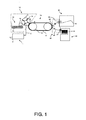
- Fig. 1 shows a print engine for printing images.
- the print engine comprises a converter 1 to convert image data into a print signal, an image forming module 10 to apply marking material corresponding to the print signal, the marking material being brought in contact with the image forming element 11 by a developing unit 13, an intermediate member 16 for transferring the marking material to the image fixing module 20, an image receiving member input station 30 for bringing in an image receiving member, usually sheets media, and a delivery station 40 for receiving the finished output product.
- the marking material is conventionally toner, which comprises a resin that is softened by heat.
- the image data are supplied to the print engine through a data connection 2.
- the converter 1 comprises electronic circuits including programmable logic to convert an image line into a print signal that is suitable to be applied to the image forming module 10 through a data connection 3.
- the image forming module 10 comprises a rotatable, substantially cylindrically shaped image forming element 11 having an electronic device 12 in the inside to apply a voltage on conductive tracks under a dielectric layer on an outer surface of the image forming element. This voltage induces a local electric field outside the image forming element that attracts toner particles from developing roller 15 that receives the toner particles from a toner supply unit 14 . In this way an image of toner particles is formed on the surface of the image forming element 11.
- the image forming element 11 may comprise a roller with a photoconductive layer on the outside surface of the roller.
- the surface of the photoconductive layer is charged by e.g. a corona and the print signals are applied to an imaging unit outside the roller.
- the imaging unit may comprise a LED-bar, or a laser scan module, that locally illuminates the layer conform the image to be printed.
- the photoconductivity of the layer results in a locally discharged surface.
- the parts of the photoconductive layer that remain charged may be used to attract toner from a toner roller like developing roller 15 by creating an electric field between these charged parts and the toner roller.
- an electric field between the charged parts and the toner roller may be provided by connecting the toner roller to a ground voltage.
- the toner may comprise electrically conductive particles having a specified colour or a mixture of isolating coloured particles and carrier particles that charge the isolating particles, making them sensitive to an electric field between the developing roller and the image forming element.
- the developing roller may also be supplemented by a contact roller that charges the toner particles. Therefore there are various ways to obtain an image of toner particles on the surface of the image forming element. In the process of forming the image the element rotates in the direction indicated by the arrow in Fig. 1 . It is further noted that in another embodiment, an imaging forming element is formed by arranging a belt with a photoconductive layer on several rollers.
- the intermediate member 16 comprises a belt 17 and two guiding rollers 18, but more rollers are also possible.
- the belt 17 rotates in congruence with the image forming element 11 and receives the toner image in a nip where the image forming element 11 and the belt 17 are in contact.
- the transfer of toner may take place by the influence of mechanical forces that are induced when the top layer of the belt comprises an elastic, adhesive material, such as rubber, or by the influence of electric forces that originate from a voltage difference between the image forming element and the belt.
- the intermediate member 16 may further comprise a heating unit, which is not shown in Fig. 1 , to control the temperature of the belt. Although only one image forming element is shown in Fig.
- the intermediate member may be configured to have several image forming elements around it, each for a different process colour of toner particles that are collected on the belt. In this way a full colour image may be formed, e.g. by the process colours cyan, magenta, yellow and black.
- the intermediate member may also be configured as a drum with an outer layer that is suitable to collect the various colour particles.
- the image fixing module 20 is able to transport an image receiving member, such as a sheet of paper, by transport rollers 21 and guiding means 22 to a pressure roller 23 that brings the image receiving member into contact with the belt 17 of the intermediate member 16.
- the image receiving member is supplied by an image receiving member input station 30 comprising a pile of sheets 31. By applying heat and pressure the toner is brought onto the image receiving member, which is transported further towards the output station 40.
- the image fixing module may comprise a path for turning the image receiving member to be able to print another side.
- the fusing rollers 24 raise the temperature of the image receiving member to further fix the printed image on the image receiving member and to enhance the printed image quality. When the temperature of the pressure roller 23 is sufficiently high, no fusing rollers are necessary.
- the print media discharge unit (not shown) is mounted along guiding means 22.
- the finished output product module 40 is shown as a tray 41, on which different sheets may be stacked, but may also comprise a stapler, a hole pucher etc. for performing a post processing step.
- the various modules are controlled by a control unit to have their actions coordinated.
- Fig. 2 shows a schematic cross-sectional view of the discharge unit 50 according to the present invention.
- Print media discharge unit 50 comprises a first electrically isolating print media guide 60 mounted over a second electrically isolating print media guide 61.
- the second isolating print media guide forms the bottom media guide and due to a spacing between the first guide 60 and the second guide 61 a print media transport path 55 is defined in between the first and second isolating media guides 60, 61 to facilitate a print media transport through this print media transport path 55 in a transport direction T.
- Sheets of print media are fed through this paper path by means of an upstream portion of the metal print media guides 80 and 81 from the print engine and fixation station.
- the sheets of print media are fed through the discharge unit 50 via metal print media guides 90 and 91 towards a downstream processing unit, such as in casu a high capacity stacker to form a stack of sheets from the incoming subsequently fed sheets of print media.
- the isolating elements defining the media transport path 55 through the discharge unit 50 comprise apertures through which an electrically grounded brush 70 with conducting brush fibres is mounted such that the fibres contact a print media during its transport through the discharge unit.
- the isolating print media guides 60, 61 comprise mounting sections to enable easy replacement of the discharge unit into the printing system by means of a click on/off system facilitated by grippers 66, 67, 68, 69.
- Fig. 3 shows a schematic top view of a detail of the discharge unit according to the present invention.
- the brush 70 can be an integral unit or distributed into a plurality of smaller brushes.
- the isolating top portion of the media guide 60 comprises slanted ribs at an angle with respect to the direction of transport T. This increases the robustness for defects in print media such as dog ears or tears. In particular locally at the brush 70 where the sheet of print media physically engages with the brush 70.
- Fig. 4 shows a schematic bottom view of a portion of the discharge unit according to the present invention.
- the bottom metal print media guides 81 and 91 are formed as an integral single piece of sheet metal with a large aperture to receive the discharge station.
- the upstream and downstream media guides are formed as separate pieces mounted to a supporting frame.
- the upstream sheet metal guide element 81 comprises two additional apertures 85 and 85' to accommodate drive rollers (not shown) to transport the sheet of print media.
- the isolating portion of the bottom media guide 61 comprises guide ribs and is mounted to the metal guide element by means of the click on/off mechanism.
- Fig. 5 shows a schematic top view of a portion of the discharge unit according to the present invention.
- the top metal print media guides 80 and 90 are formed as an integral single piece of sheet metal with a large aperture to receive the discharge station.
- the upstream and downstream media guides are formed as separate pieces mounted to a supporting frame.
- the upstream sheet metal guide element 80 comprises two additional apertures 95 and 95' to accommodate drive rollers (not shown) to transport the sheet of print media.
- the isolating portion of the bottom media guide 60 comprises guide ribs and is mounted to the metal guide element by means of the click on/off mechanism. The space between the ribs of guide element 60 accommodate the electrically grounded brush 70.
- plurality is defined as two or more than two.
- another is defined as at least a second or more.
- the terms including and/or having, as used herein, are defined as comprising (i.e., open language).
- coupled is defined as connected, although not necessarily directly.
Landscapes
- Engineering & Computer Science (AREA)
- Mechanical Engineering (AREA)
- Physics & Mathematics (AREA)
- General Physics & Mathematics (AREA)
- Feeding Of Articles By Means Other Than Belts Or Rollers (AREA)
Priority Applications (1)
| Application Number | Priority Date | Filing Date | Title |
|---|---|---|---|
| EP15176944.5A EP2993149B1 (de) | 2014-07-28 | 2015-07-16 | Druckmedienentladungseinheit, sowie dazugehörige druckmedienführungsanordnung, blattstapelvorrichtung, bildwiedergabevorrichtung, und verfahren zur modifizierung einer bildwiedergabevorrichtung |
Applications Claiming Priority (2)
| Application Number | Priority Date | Filing Date | Title |
|---|---|---|---|
| EP14178784 | 2014-07-28 | ||
| EP15176944.5A EP2993149B1 (de) | 2014-07-28 | 2015-07-16 | Druckmedienentladungseinheit, sowie dazugehörige druckmedienführungsanordnung, blattstapelvorrichtung, bildwiedergabevorrichtung, und verfahren zur modifizierung einer bildwiedergabevorrichtung |
Publications (2)
| Publication Number | Publication Date |
|---|---|
| EP2993149A1 true EP2993149A1 (de) | 2016-03-09 |
| EP2993149B1 EP2993149B1 (de) | 2017-09-13 |
Family
ID=51229827
Family Applications (1)
| Application Number | Title | Priority Date | Filing Date |
|---|---|---|---|
| EP15176944.5A Not-in-force EP2993149B1 (de) | 2014-07-28 | 2015-07-16 | Druckmedienentladungseinheit, sowie dazugehörige druckmedienführungsanordnung, blattstapelvorrichtung, bildwiedergabevorrichtung, und verfahren zur modifizierung einer bildwiedergabevorrichtung |
Country Status (2)
| Country | Link |
|---|---|
| US (1) | US9567179B2 (de) |
| EP (1) | EP2993149B1 (de) |
Families Citing this family (2)
| Publication number | Priority date | Publication date | Assignee | Title |
|---|---|---|---|---|
| JP6658373B2 (ja) * | 2016-07-19 | 2020-03-04 | 京セラドキュメントソリューションズ株式会社 | 画像形成装置 |
| WO2018116469A1 (ja) * | 2016-12-22 | 2018-06-28 | 富士通フロンテック株式会社 | 紙葉類取扱装置及び異物検知方法 |
Citations (3)
| Publication number | Priority date | Publication date | Assignee | Title |
|---|---|---|---|---|
| US4494166A (en) | 1982-09-21 | 1985-01-15 | Xerox Corporation | Printing machine with static elimination system |
| JPS60105160U (ja) * | 1983-12-23 | 1985-07-18 | セイコーインスツルメンツ株式会社 | 記録装置における除電機構 |
| US20060083569A1 (en) * | 2004-10-18 | 2006-04-20 | Samsung Electronics Co., Ltd. | Paper discharging guide unit and wet image forming apparatus having the same |
Family Cites Families (6)
| Publication number | Priority date | Publication date | Assignee | Title |
|---|---|---|---|---|
| DE3272661D1 (en) * | 1981-03-02 | 1986-09-25 | Mita Industrial Co Ltd | Improved paper feeding device and paper guiding device in a copying apparatus |
| US4771360A (en) * | 1987-03-20 | 1988-09-13 | Xerox Corporation | Grounding brush |
| US4994861A (en) * | 1989-06-30 | 1991-02-19 | International Business Machines Corporation | Printing machine with charge neutralizing system |
| JP2005089065A (ja) * | 2003-09-17 | 2005-04-07 | Ricoh Co Ltd | シート搬送装置及びそれを備える画像形成装置、画像読取装置、後処理装置 |
| JP4646008B2 (ja) * | 2008-06-30 | 2011-03-09 | 株式会社沖データ | 媒体搬送装置及び画像形成装置 |
| JP6020241B2 (ja) * | 2013-02-18 | 2016-11-02 | ブラザー工業株式会社 | インクジェット記録装置 |
-
2015
- 2015-07-16 EP EP15176944.5A patent/EP2993149B1/de not_active Not-in-force
- 2015-07-20 US US14/804,039 patent/US9567179B2/en not_active Expired - Fee Related
Patent Citations (3)
| Publication number | Priority date | Publication date | Assignee | Title |
|---|---|---|---|---|
| US4494166A (en) | 1982-09-21 | 1985-01-15 | Xerox Corporation | Printing machine with static elimination system |
| JPS60105160U (ja) * | 1983-12-23 | 1985-07-18 | セイコーインスツルメンツ株式会社 | 記録装置における除電機構 |
| US20060083569A1 (en) * | 2004-10-18 | 2006-04-20 | Samsung Electronics Co., Ltd. | Paper discharging guide unit and wet image forming apparatus having the same |
Also Published As
| Publication number | Publication date |
|---|---|
| US9567179B2 (en) | 2017-02-14 |
| US20160185554A1 (en) | 2016-06-30 |
| EP2993149B1 (de) | 2017-09-13 |
Similar Documents
| Publication | Publication Date | Title |
|---|---|---|
| CN102837983B (zh) | 片材给送装置和成像装置 | |
| US20080317532A1 (en) | Image forming apparatus | |
| US8358955B2 (en) | Transfer device and image forming apparatus | |
| JP6460724B2 (ja) | 画像形成装置 | |
| US9567179B2 (en) | Print media discharge unit | |
| US9513581B2 (en) | Transfer device, image forming apparatus | |
| JP6558941B2 (ja) | 画像形成装置 | |
| US8335462B2 (en) | Image forming apparatus | |
| US8750734B2 (en) | Transfer device and image forming apparatus including same | |
| US7533879B2 (en) | Variable frequency tampers for coated stocks used in paper feed trays | |
| US20160209787A1 (en) | Transfer device, image forming apparatus | |
| CN102141759A (zh) | 成像设备 | |
| JP5090982B2 (ja) | 画像形成装置 | |
| EP3059638B1 (de) | Bilderzeugungsvorrichtung | |
| JP5564876B2 (ja) | 記録媒体供給装置及び画像形成装置 | |
| CN108604078A (zh) | 成像设备 | |
| US20110316953A1 (en) | Recording medium holding device and image forming apparatus | |
| US9150370B2 (en) | Sheet feeder and image forming apparatus incorporating same | |
| JP2014035357A (ja) | 画像形成装置 | |
| US8422933B2 (en) | Curved pre-fuser transport to enable larger sheets through a xerographic print engine | |
| JP2010044317A (ja) | 画像形成装置 | |
| JP4500656B2 (ja) | 構造体及び画像形成装置 | |
| JP2013109243A (ja) | 定着装置及び電子写真印刷装置 | |
| JP2013242596A (ja) | 画像形成装置 | |
| JP4251412B2 (ja) | トナー付着シートの静電搬送システム |
Legal Events
| Date | Code | Title | Description |
|---|---|---|---|
| PUAI | Public reference made under article 153(3) epc to a published international application that has entered the european phase |
Free format text: ORIGINAL CODE: 0009012 |
|
| AK | Designated contracting states |
Kind code of ref document: A1 Designated state(s): AL AT BE BG CH CY CZ DE DK EE ES FI FR GB GR HR HU IE IS IT LI LT LU LV MC MK MT NL NO PL PT RO RS SE SI SK SM TR |
|
| AX | Request for extension of the european patent |
Extension state: BA ME |
|
| 17P | Request for examination filed |
Effective date: 20160909 |
|
| RBV | Designated contracting states (corrected) |
Designated state(s): AL AT BE BG CH CY CZ DE DK EE ES FI FR GB GR HR HU IE IS IT LI LT LU LV MC MK MT NL NO PL PT RO RS SE SI SK SM TR |
|
| GRAP | Despatch of communication of intention to grant a patent |
Free format text: ORIGINAL CODE: EPIDOSNIGR1 |
|
| RIC1 | Information provided on ipc code assigned before grant |
Ipc: G03G 15/00 20060101ALI20170203BHEP Ipc: B65H 29/52 20060101AFI20170203BHEP |
|
| STAA | Information on the status of an ep patent application or granted ep patent |
Free format text: STATUS: GRANT OF PATENT IS INTENDED |
|
| INTG | Intention to grant announced |
Effective date: 20170316 |
|
| GRAS | Grant fee paid |
Free format text: ORIGINAL CODE: EPIDOSNIGR3 |
|
| GRAA | (expected) grant |
Free format text: ORIGINAL CODE: 0009210 |
|
| STAA | Information on the status of an ep patent application or granted ep patent |
Free format text: STATUS: THE PATENT HAS BEEN GRANTED |
|
| AK | Designated contracting states |
Kind code of ref document: B1 Designated state(s): AL AT BE BG CH CY CZ DE DK EE ES FI FR GB GR HR HU IE IS IT LI LT LU LV MC MK MT NL NO PL PT RO RS SE SI SK SM TR |
|
| REG | Reference to a national code |
Ref country code: GB Ref legal event code: FG4D |
|
| REG | Reference to a national code |
Ref country code: CH Ref legal event code: EP |
|
| REG | Reference to a national code |
Ref country code: IE Ref legal event code: FG4D |
|
| REG | Reference to a national code |
Ref country code: AT Ref legal event code: REF Ref document number: 927920 Country of ref document: AT Kind code of ref document: T Effective date: 20171015 |
|
| REG | Reference to a national code |
Ref country code: DE Ref legal event code: R096 Ref document number: 602015004652 Country of ref document: DE |
|
| REG | Reference to a national code |
Ref country code: NL Ref legal event code: FP |
|
| REG | Reference to a national code |
Ref country code: LT Ref legal event code: MG4D |
|
| PG25 | Lapsed in a contracting state [announced via postgrant information from national office to epo] |
Ref country code: HR Free format text: LAPSE BECAUSE OF FAILURE TO SUBMIT A TRANSLATION OF THE DESCRIPTION OR TO PAY THE FEE WITHIN THE PRESCRIBED TIME-LIMIT Effective date: 20170913 Ref country code: LT Free format text: LAPSE BECAUSE OF FAILURE TO SUBMIT A TRANSLATION OF THE DESCRIPTION OR TO PAY THE FEE WITHIN THE PRESCRIBED TIME-LIMIT Effective date: 20170913 Ref country code: SE Free format text: LAPSE BECAUSE OF FAILURE TO SUBMIT A TRANSLATION OF THE DESCRIPTION OR TO PAY THE FEE WITHIN THE PRESCRIBED TIME-LIMIT Effective date: 20170913 Ref country code: FI Free format text: LAPSE BECAUSE OF FAILURE TO SUBMIT A TRANSLATION OF THE DESCRIPTION OR TO PAY THE FEE WITHIN THE PRESCRIBED TIME-LIMIT Effective date: 20170913 Ref country code: NO Free format text: LAPSE BECAUSE OF FAILURE TO SUBMIT A TRANSLATION OF THE DESCRIPTION OR TO PAY THE FEE WITHIN THE PRESCRIBED TIME-LIMIT Effective date: 20171213 |
|
| REG | Reference to a national code |
Ref country code: AT Ref legal event code: MK05 Ref document number: 927920 Country of ref document: AT Kind code of ref document: T Effective date: 20170913 |
|
| PG25 | Lapsed in a contracting state [announced via postgrant information from national office to epo] |
Ref country code: LV Free format text: LAPSE BECAUSE OF FAILURE TO SUBMIT A TRANSLATION OF THE DESCRIPTION OR TO PAY THE FEE WITHIN THE PRESCRIBED TIME-LIMIT Effective date: 20170913 Ref country code: BG Free format text: LAPSE BECAUSE OF FAILURE TO SUBMIT A TRANSLATION OF THE DESCRIPTION OR TO PAY THE FEE WITHIN THE PRESCRIBED TIME-LIMIT Effective date: 20171213 Ref country code: ES Free format text: LAPSE BECAUSE OF FAILURE TO SUBMIT A TRANSLATION OF THE DESCRIPTION OR TO PAY THE FEE WITHIN THE PRESCRIBED TIME-LIMIT Effective date: 20170913 Ref country code: RS Free format text: LAPSE BECAUSE OF FAILURE TO SUBMIT A TRANSLATION OF THE DESCRIPTION OR TO PAY THE FEE WITHIN THE PRESCRIBED TIME-LIMIT Effective date: 20170913 Ref country code: GR Free format text: LAPSE BECAUSE OF FAILURE TO SUBMIT A TRANSLATION OF THE DESCRIPTION OR TO PAY THE FEE WITHIN THE PRESCRIBED TIME-LIMIT Effective date: 20171214 |
|
| PG25 | Lapsed in a contracting state [announced via postgrant information from national office to epo] |
Ref country code: PL Free format text: LAPSE BECAUSE OF FAILURE TO SUBMIT A TRANSLATION OF THE DESCRIPTION OR TO PAY THE FEE WITHIN THE PRESCRIBED TIME-LIMIT Effective date: 20170913 Ref country code: RO Free format text: LAPSE BECAUSE OF FAILURE TO SUBMIT A TRANSLATION OF THE DESCRIPTION OR TO PAY THE FEE WITHIN THE PRESCRIBED TIME-LIMIT Effective date: 20170913 Ref country code: CZ Free format text: LAPSE BECAUSE OF FAILURE TO SUBMIT A TRANSLATION OF THE DESCRIPTION OR TO PAY THE FEE WITHIN THE PRESCRIBED TIME-LIMIT Effective date: 20170913 |
|
| PG25 | Lapsed in a contracting state [announced via postgrant information from national office to epo] |
Ref country code: IT Free format text: LAPSE BECAUSE OF FAILURE TO SUBMIT A TRANSLATION OF THE DESCRIPTION OR TO PAY THE FEE WITHIN THE PRESCRIBED TIME-LIMIT Effective date: 20170913 Ref country code: IS Free format text: LAPSE BECAUSE OF FAILURE TO SUBMIT A TRANSLATION OF THE DESCRIPTION OR TO PAY THE FEE WITHIN THE PRESCRIBED TIME-LIMIT Effective date: 20180113 Ref country code: EE Free format text: LAPSE BECAUSE OF FAILURE TO SUBMIT A TRANSLATION OF THE DESCRIPTION OR TO PAY THE FEE WITHIN THE PRESCRIBED TIME-LIMIT Effective date: 20170913 Ref country code: SK Free format text: LAPSE BECAUSE OF FAILURE TO SUBMIT A TRANSLATION OF THE DESCRIPTION OR TO PAY THE FEE WITHIN THE PRESCRIBED TIME-LIMIT Effective date: 20170913 Ref country code: AT Free format text: LAPSE BECAUSE OF FAILURE TO SUBMIT A TRANSLATION OF THE DESCRIPTION OR TO PAY THE FEE WITHIN THE PRESCRIBED TIME-LIMIT Effective date: 20170913 Ref country code: SM Free format text: LAPSE BECAUSE OF FAILURE TO SUBMIT A TRANSLATION OF THE DESCRIPTION OR TO PAY THE FEE WITHIN THE PRESCRIBED TIME-LIMIT Effective date: 20170913 |
|
| REG | Reference to a national code |
Ref country code: DE Ref legal event code: R097 Ref document number: 602015004652 Country of ref document: DE |
|
| PLBE | No opposition filed within time limit |
Free format text: ORIGINAL CODE: 0009261 |
|
| STAA | Information on the status of an ep patent application or granted ep patent |
Free format text: STATUS: NO OPPOSITION FILED WITHIN TIME LIMIT |
|
| REG | Reference to a national code |
Ref country code: FR Ref legal event code: PLFP Year of fee payment: 4 |
|
| PG25 | Lapsed in a contracting state [announced via postgrant information from national office to epo] |
Ref country code: DK Free format text: LAPSE BECAUSE OF FAILURE TO SUBMIT A TRANSLATION OF THE DESCRIPTION OR TO PAY THE FEE WITHIN THE PRESCRIBED TIME-LIMIT Effective date: 20170913 |
|
| 26N | No opposition filed |
Effective date: 20180614 |
|
| PGFP | Annual fee paid to national office [announced via postgrant information from national office to epo] |
Ref country code: FR Payment date: 20180727 Year of fee payment: 4 Ref country code: DE Payment date: 20180723 Year of fee payment: 4 Ref country code: NL Payment date: 20180724 Year of fee payment: 4 |
|
| PG25 | Lapsed in a contracting state [announced via postgrant information from national office to epo] |
Ref country code: SI Free format text: LAPSE BECAUSE OF FAILURE TO SUBMIT A TRANSLATION OF THE DESCRIPTION OR TO PAY THE FEE WITHIN THE PRESCRIBED TIME-LIMIT Effective date: 20170913 |
|
| REG | Reference to a national code |
Ref country code: CH Ref legal event code: PL |
|
| PG25 | Lapsed in a contracting state [announced via postgrant information from national office to epo] |
Ref country code: MC Free format text: LAPSE BECAUSE OF FAILURE TO SUBMIT A TRANSLATION OF THE DESCRIPTION OR TO PAY THE FEE WITHIN THE PRESCRIBED TIME-LIMIT Effective date: 20170913 Ref country code: LU Free format text: LAPSE BECAUSE OF NON-PAYMENT OF DUE FEES Effective date: 20180716 |
|
| REG | Reference to a national code |
Ref country code: BE Ref legal event code: MM Effective date: 20180731 |
|
| REG | Reference to a national code |
Ref country code: IE Ref legal event code: MM4A |
|
| PG25 | Lapsed in a contracting state [announced via postgrant information from national office to epo] |
Ref country code: IE Free format text: LAPSE BECAUSE OF NON-PAYMENT OF DUE FEES Effective date: 20180716 Ref country code: LI Free format text: LAPSE BECAUSE OF NON-PAYMENT OF DUE FEES Effective date: 20180731 Ref country code: CH Free format text: LAPSE BECAUSE OF NON-PAYMENT OF DUE FEES Effective date: 20180731 |
|
| PG25 | Lapsed in a contracting state [announced via postgrant information from national office to epo] |
Ref country code: BE Free format text: LAPSE BECAUSE OF NON-PAYMENT OF DUE FEES Effective date: 20180731 |
|
| PG25 | Lapsed in a contracting state [announced via postgrant information from national office to epo] |
Ref country code: MT Free format text: LAPSE BECAUSE OF NON-PAYMENT OF DUE FEES Effective date: 20180716 |
|
| REG | Reference to a national code |
Ref country code: DE Ref legal event code: R119 Ref document number: 602015004652 Country of ref document: DE |
|
| GBPC | Gb: european patent ceased through non-payment of renewal fee |
Effective date: 20190716 |
|
| PG25 | Lapsed in a contracting state [announced via postgrant information from national office to epo] |
Ref country code: TR Free format text: LAPSE BECAUSE OF FAILURE TO SUBMIT A TRANSLATION OF THE DESCRIPTION OR TO PAY THE FEE WITHIN THE PRESCRIBED TIME-LIMIT Effective date: 20170913 |
|
| PG25 | Lapsed in a contracting state [announced via postgrant information from national office to epo] |
Ref country code: GB Free format text: LAPSE BECAUSE OF NON-PAYMENT OF DUE FEES Effective date: 20190716 Ref country code: DE Free format text: LAPSE BECAUSE OF NON-PAYMENT OF DUE FEES Effective date: 20200201 Ref country code: NL Free format text: LAPSE BECAUSE OF NON-PAYMENT OF DUE FEES Effective date: 20190801 |
|
| REG | Reference to a national code |
Ref country code: NL Ref legal event code: MM Effective date: 20190801 |
|
| PG25 | Lapsed in a contracting state [announced via postgrant information from national office to epo] |
Ref country code: PT Free format text: LAPSE BECAUSE OF FAILURE TO SUBMIT A TRANSLATION OF THE DESCRIPTION OR TO PAY THE FEE WITHIN THE PRESCRIBED TIME-LIMIT Effective date: 20170913 |
|
| PG25 | Lapsed in a contracting state [announced via postgrant information from national office to epo] |
Ref country code: MK Free format text: LAPSE BECAUSE OF NON-PAYMENT OF DUE FEES Effective date: 20170913 Ref country code: HU Free format text: LAPSE BECAUSE OF FAILURE TO SUBMIT A TRANSLATION OF THE DESCRIPTION OR TO PAY THE FEE WITHIN THE PRESCRIBED TIME-LIMIT; INVALID AB INITIO Effective date: 20150716 Ref country code: FR Free format text: LAPSE BECAUSE OF NON-PAYMENT OF DUE FEES Effective date: 20190731 Ref country code: CY Free format text: LAPSE BECAUSE OF FAILURE TO SUBMIT A TRANSLATION OF THE DESCRIPTION OR TO PAY THE FEE WITHIN THE PRESCRIBED TIME-LIMIT Effective date: 20170913 |
|
| PG25 | Lapsed in a contracting state [announced via postgrant information from national office to epo] |
Ref country code: AL Free format text: LAPSE BECAUSE OF FAILURE TO SUBMIT A TRANSLATION OF THE DESCRIPTION OR TO PAY THE FEE WITHIN THE PRESCRIBED TIME-LIMIT Effective date: 20170913 |