EP2993305A1 - Élements de remplissage d'un ventilateur d'une turbine a gaz - Google Patents
Élements de remplissage d'un ventilateur d'une turbine a gaz Download PDFInfo
- Publication number
- EP2993305A1 EP2993305A1 EP15182031.3A EP15182031A EP2993305A1 EP 2993305 A1 EP2993305 A1 EP 2993305A1 EP 15182031 A EP15182031 A EP 15182031A EP 2993305 A1 EP2993305 A1 EP 2993305A1
- Authority
- EP
- European Patent Office
- Prior art keywords
- gas turbine
- fan
- aircraft gas
- projection
- turbine according
- Prior art date
- Legal status (The legal status is an assumption and is not a legal conclusion. Google has not performed a legal analysis and makes no representation as to the accuracy of the status listed.)
- Granted
Links
- 238000007789 sealing Methods 0.000 claims abstract description 16
- 230000003014 reinforcing effect Effects 0.000 claims description 5
- 238000003780 insertion Methods 0.000 claims description 4
- 230000037431 insertion Effects 0.000 claims description 4
- 238000005452 bending Methods 0.000 claims description 2
- 238000004519 manufacturing process Methods 0.000 description 8
- 238000013459 approach Methods 0.000 description 4
- 238000010276 construction Methods 0.000 description 4
- 229920002430 Fibre-reinforced plastic Polymers 0.000 description 3
- 238000000748 compression moulding Methods 0.000 description 3
- 239000011151 fibre-reinforced plastic Substances 0.000 description 3
- 240000006829 Ficus sundaica Species 0.000 description 2
- XAGFODPZIPBFFR-UHFFFAOYSA-N aluminium Chemical compound [Al] XAGFODPZIPBFFR-UHFFFAOYSA-N 0.000 description 2
- 229910052782 aluminium Inorganic materials 0.000 description 2
- 238000002485 combustion reaction Methods 0.000 description 2
- 238000013461 design Methods 0.000 description 2
- 239000000835 fiber Substances 0.000 description 2
- 239000000945 filler Substances 0.000 description 2
- 238000001746 injection moulding Methods 0.000 description 2
- 238000009745 resin transfer moulding Methods 0.000 description 2
- 229920000049 Carbon (fiber) Polymers 0.000 description 1
- 239000004917 carbon fiber Substances 0.000 description 1
- 230000001419 dependent effect Effects 0.000 description 1
- 238000005516 engineering process Methods 0.000 description 1
- 239000003365 glass fiber Substances 0.000 description 1
- 238000002347 injection Methods 0.000 description 1
- 239000007924 injection Substances 0.000 description 1
- 238000009434 installation Methods 0.000 description 1
- 238000003754 machining Methods 0.000 description 1
- 238000003801 milling Methods 0.000 description 1
- 238000012986 modification Methods 0.000 description 1
- 230000004048 modification Effects 0.000 description 1
- 230000002787 reinforcement Effects 0.000 description 1
- 239000012783 reinforcing fiber Substances 0.000 description 1
- 239000011347 resin Substances 0.000 description 1
- 229920005989 resin Polymers 0.000 description 1
- 238000003860 storage Methods 0.000 description 1
- 238000001721 transfer moulding Methods 0.000 description 1
- 239000013585 weight reducing agent Substances 0.000 description 1
Images


Classifications
-
- F—MECHANICAL ENGINEERING; LIGHTING; HEATING; WEAPONS; BLASTING
- F01—MACHINES OR ENGINES IN GENERAL; ENGINE PLANTS IN GENERAL; STEAM ENGINES
- F01D—NON-POSITIVE DISPLACEMENT MACHINES OR ENGINES, e.g. STEAM TURBINES
- F01D5/00—Blades; Blade-carrying members; Heating, heat-insulating, cooling or antivibration means on the blades or the members
- F01D5/02—Blade-carrying members, e.g. rotors
- F01D5/027—Arrangements for balancing
-
- F—MECHANICAL ENGINEERING; LIGHTING; HEATING; WEAPONS; BLASTING
- F01—MACHINES OR ENGINES IN GENERAL; ENGINE PLANTS IN GENERAL; STEAM ENGINES
- F01D—NON-POSITIVE DISPLACEMENT MACHINES OR ENGINES, e.g. STEAM TURBINES
- F01D25/00—Component parts, details, or accessories, not provided for in, or of interest apart from, other groups
- F01D25/28—Supporting or mounting arrangements, e.g. for turbine casing
-
- F—MECHANICAL ENGINEERING; LIGHTING; HEATING; WEAPONS; BLASTING
- F01—MACHINES OR ENGINES IN GENERAL; ENGINE PLANTS IN GENERAL; STEAM ENGINES
- F01D—NON-POSITIVE DISPLACEMENT MACHINES OR ENGINES, e.g. STEAM TURBINES
- F01D11/00—Preventing or minimising internal leakage of working-fluid, e.g. between stages
-
- F—MECHANICAL ENGINEERING; LIGHTING; HEATING; WEAPONS; BLASTING
- F01—MACHINES OR ENGINES IN GENERAL; ENGINE PLANTS IN GENERAL; STEAM ENGINES
- F01D—NON-POSITIVE DISPLACEMENT MACHINES OR ENGINES, e.g. STEAM TURBINES
- F01D11/00—Preventing or minimising internal leakage of working-fluid, e.g. between stages
- F01D11/005—Sealing means between non relatively rotating elements
- F01D11/006—Sealing the gap between rotor blades or blades and rotor
- F01D11/008—Sealing the gap between rotor blades or blades and rotor by spacer elements between the blades, e.g. independent interblade platforms
-
- F—MECHANICAL ENGINEERING; LIGHTING; HEATING; WEAPONS; BLASTING
- F01—MACHINES OR ENGINES IN GENERAL; ENGINE PLANTS IN GENERAL; STEAM ENGINES
- F01D—NON-POSITIVE DISPLACEMENT MACHINES OR ENGINES, e.g. STEAM TURBINES
- F01D5/00—Blades; Blade-carrying members; Heating, heat-insulating, cooling or antivibration means on the blades or the members
- F01D5/02—Blade-carrying members, e.g. rotors
-
- F—MECHANICAL ENGINEERING; LIGHTING; HEATING; WEAPONS; BLASTING
- F01—MACHINES OR ENGINES IN GENERAL; ENGINE PLANTS IN GENERAL; STEAM ENGINES
- F01D—NON-POSITIVE DISPLACEMENT MACHINES OR ENGINES, e.g. STEAM TURBINES
- F01D5/00—Blades; Blade-carrying members; Heating, heat-insulating, cooling or antivibration means on the blades or the members
- F01D5/12—Blades
-
- F—MECHANICAL ENGINEERING; LIGHTING; HEATING; WEAPONS; BLASTING
- F01—MACHINES OR ENGINES IN GENERAL; ENGINE PLANTS IN GENERAL; STEAM ENGINES
- F01D—NON-POSITIVE DISPLACEMENT MACHINES OR ENGINES, e.g. STEAM TURBINES
- F01D5/00—Blades; Blade-carrying members; Heating, heat-insulating, cooling or antivibration means on the blades or the members
- F01D5/30—Fixing blades to rotors; Blade roots ; Blade spacers
-
- F—MECHANICAL ENGINEERING; LIGHTING; HEATING; WEAPONS; BLASTING
- F01—MACHINES OR ENGINES IN GENERAL; ENGINE PLANTS IN GENERAL; STEAM ENGINES
- F01D—NON-POSITIVE DISPLACEMENT MACHINES OR ENGINES, e.g. STEAM TURBINES
- F01D5/00—Blades; Blade-carrying members; Heating, heat-insulating, cooling or antivibration means on the blades or the members
- F01D5/30—Fixing blades to rotors; Blade roots ; Blade spacers
- F01D5/3007—Fixing blades to rotors; Blade roots ; Blade spacers of axial insertion type
- F01D5/3015—Fixing blades to rotors; Blade roots ; Blade spacers of axial insertion type with side plates
-
- F—MECHANICAL ENGINEERING; LIGHTING; HEATING; WEAPONS; BLASTING
- F01—MACHINES OR ENGINES IN GENERAL; ENGINE PLANTS IN GENERAL; STEAM ENGINES
- F01D—NON-POSITIVE DISPLACEMENT MACHINES OR ENGINES, e.g. STEAM TURBINES
- F01D5/00—Blades; Blade-carrying members; Heating, heat-insulating, cooling or antivibration means on the blades or the members
- F01D5/30—Fixing blades to rotors; Blade roots ; Blade spacers
- F01D5/32—Locking, e.g. by final locking blades or keys
- F01D5/323—Locking of axial insertion type blades by means of a key or the like parallel to the axis of the rotor
-
- F—MECHANICAL ENGINEERING; LIGHTING; HEATING; WEAPONS; BLASTING
- F01—MACHINES OR ENGINES IN GENERAL; ENGINE PLANTS IN GENERAL; STEAM ENGINES
- F01D—NON-POSITIVE DISPLACEMENT MACHINES OR ENGINES, e.g. STEAM TURBINES
- F01D5/00—Blades; Blade-carrying members; Heating, heat-insulating, cooling or antivibration means on the blades or the members
- F01D5/30—Fixing blades to rotors; Blade roots ; Blade spacers
- F01D5/32—Locking, e.g. by final locking blades or keys
- F01D5/326—Locking of axial insertion type blades by other means
-
- F—MECHANICAL ENGINEERING; LIGHTING; HEATING; WEAPONS; BLASTING
- F01—MACHINES OR ENGINES IN GENERAL; ENGINE PLANTS IN GENERAL; STEAM ENGINES
- F01D—NON-POSITIVE DISPLACEMENT MACHINES OR ENGINES, e.g. STEAM TURBINES
- F01D9/00—Stators
- F01D9/02—Nozzles; Nozzle boxes; Stator blades; Guide conduits, e.g. individual nozzles
-
- F—MECHANICAL ENGINEERING; LIGHTING; HEATING; WEAPONS; BLASTING
- F02—COMBUSTION ENGINES; HOT-GAS OR COMBUSTION-PRODUCT ENGINE PLANTS
- F02C—GAS-TURBINE PLANTS; AIR INTAKES FOR JET-PROPULSION PLANTS; CONTROLLING FUEL SUPPLY IN AIR-BREATHING JET-PROPULSION PLANTS
- F02C7/00—Features, components parts, details or accessories, not provided for in, or of interest apart form groups F02C1/00 - F02C6/00; Air intakes for jet-propulsion plants
- F02C7/04—Air intakes for gas-turbine plants or jet-propulsion plants
-
- F—MECHANICAL ENGINEERING; LIGHTING; HEATING; WEAPONS; BLASTING
- F05—INDEXING SCHEMES RELATING TO ENGINES OR PUMPS IN VARIOUS SUBCLASSES OF CLASSES F01-F04
- F05D—INDEXING SCHEME FOR ASPECTS RELATING TO NON-POSITIVE-DISPLACEMENT MACHINES OR ENGINES, GAS-TURBINES OR JET-PROPULSION PLANTS
- F05D2220/00—Application
- F05D2220/30—Application in turbines
- F05D2220/32—Application in turbines in gas turbines
- F05D2220/323—Application in turbines in gas turbines for aircraft propulsion, e.g. jet engines
-
- F—MECHANICAL ENGINEERING; LIGHTING; HEATING; WEAPONS; BLASTING
- F05—INDEXING SCHEMES RELATING TO ENGINES OR PUMPS IN VARIOUS SUBCLASSES OF CLASSES F01-F04
- F05D—INDEXING SCHEME FOR ASPECTS RELATING TO NON-POSITIVE-DISPLACEMENT MACHINES OR ENGINES, GAS-TURBINES OR JET-PROPULSION PLANTS
- F05D2230/00—Manufacture
- F05D2230/60—Assembly methods
-
- F—MECHANICAL ENGINEERING; LIGHTING; HEATING; WEAPONS; BLASTING
- F05—INDEXING SCHEMES RELATING TO ENGINES OR PUMPS IN VARIOUS SUBCLASSES OF CLASSES F01-F04
- F05D—INDEXING SCHEME FOR ASPECTS RELATING TO NON-POSITIVE-DISPLACEMENT MACHINES OR ENGINES, GAS-TURBINES OR JET-PROPULSION PLANTS
- F05D2240/00—Components
- F05D2240/10—Stators
- F05D2240/12—Fluid guiding means, e.g. vanes
- F05D2240/128—Nozzles
-
- F—MECHANICAL ENGINEERING; LIGHTING; HEATING; WEAPONS; BLASTING
- F05—INDEXING SCHEMES RELATING TO ENGINES OR PUMPS IN VARIOUS SUBCLASSES OF CLASSES F01-F04
- F05D—INDEXING SCHEME FOR ASPECTS RELATING TO NON-POSITIVE-DISPLACEMENT MACHINES OR ENGINES, GAS-TURBINES OR JET-PROPULSION PLANTS
- F05D2240/00—Components
- F05D2240/55—Seals
-
- Y—GENERAL TAGGING OF NEW TECHNOLOGICAL DEVELOPMENTS; GENERAL TAGGING OF CROSS-SECTIONAL TECHNOLOGIES SPANNING OVER SEVERAL SECTIONS OF THE IPC; TECHNICAL SUBJECTS COVERED BY FORMER USPC CROSS-REFERENCE ART COLLECTIONS [XRACs] AND DIGESTS
- Y02—TECHNOLOGIES OR APPLICATIONS FOR MITIGATION OR ADAPTATION AGAINST CLIMATE CHANGE
- Y02T—CLIMATE CHANGE MITIGATION TECHNOLOGIES RELATED TO TRANSPORTATION
- Y02T50/00—Aeronautics or air transport
- Y02T50/60—Efficient propulsion technologies, e.g. for aircraft
Definitions
- the invention relates to filling elements of a fan of a gas turbine and in particular to an aircraft gas turbine according to the features of the preamble of claim 1.
- the invention relates to an aircraft gas turbine with a fan disk, which are distributed around the circumference, to each other a space forming fan blades are attached, with a rear side arranged to the fan disc sealing washer and with a fan at the front Washer mounted inlet cone and arranged in the interstices filling elements.
- the prior art is on the GB 2 363 170 A directed.
- the prior art shows constructions in which the annulus filler is a separately manufactured component, which is usually made of aluminum and hooked to the fan disc by means of hooks.
- the filling element has the task of forming the radially inner wall of the flow channel in the spaces between the fan blades and to allow an undisturbed flow flow.
- the filling elements must satisfy the mechanical requirements, such as centrifugal forces in particular.
- the production of the filling elements is, due to their structural design, costly.
- the filling elements have a relatively large weight.
- the sealing takes place by means of organic sealing lips, which also have to be manufactured separately.
- the invention has for its object to provide a fan of an aircraft gas turbine, which avoids the disadvantages of the prior art with a simple structure and simple, cost-effective manufacturability and is provided with optimized filling elements.
- the inlet cone has integrally with this formed strip-shaped projections, which are introduced into the spaces between the fan blades.
- the free ends of the strip-shaped projections are inserted into a ring groove formed on the sealing ring or hooked under a circumferential, annular projection of the sealing disc.
- a filling element is arranged and connected thereto.
- the filling elements are no longer stored, as in the prior art, on the fan disk, so that it does not have to be provided with holding means or the like. This considerably reduces the weight of the fan disc.
- the weight reduction can be up to 10 kg.
- the manufacturing costs for the fan disk are significantly reduced.
- the filling elements are preferably designed as fiber-reinforced plastic injection molded parts or as molded parts. This makes it possible to adjust the filling elements of the predetermined by the curvature of the fan blades complex geometry of the interstices in a simple manner. Thus, it is possible to produce the filling elements accurately, so that can be dispensed with additional seals. If the organic seals are not dispensed with, they can be integrated into the Mold are inserted and integrally connected during injection molding or RTM or compression molding.
- the approaches of the inlet cone are milled after the production of the inlet cone.
- the inlet cone is thus produced in the usual way, for example as a fiber-reinforced plastic part, so that in this respect no changes to the basic construction of the inlet cone are required.
- the filling elements themselves are held on the strip-like lugs by screwing, by rivets or bolt fastenings or by projections (by using clamping wings). It is also possible according to the invention to staple these with the strip-shaped approaches or to anchor them in a form-fitting manner in other ways.
- the filling elements are thus mounted after installation of the inlet cone. This assembly can also be done with a quick release, to replace the filling elements in case of need easily.
- the lugs are preferably designed as a bending beam to have sufficient stability against the centrifugal forces occurring.
- the filling elements may preferably be made of a fiber-reinforced plastic. Both glass fibers and carbon fibers can be used. In an injection molding process thereby shorter fibers can be used, while in a compression molding (compression molding) longer reinforcing fibers can be used. Another variant is the production with continuous fiber reinforcement via the so-called RTM process (Resin Transfer Molding), here, the highest mechanical strengths are achieved at a reasonable cost.
- RTM process Resin Transfer Molding
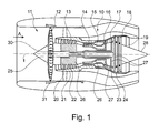
- the gas turbine engine 10 is a generalized example of a turbomachine, in which the invention can be applied.
- the engine 10 is formed in a conventional manner and comprises in succession an air inlet 11, a fan 12 circulating in a housing, a medium pressure compressor 13, a high pressure compressor 14, a combustion chamber 15, a high pressure turbine 16, a medium pressure turbine 17 and a low pressure turbine 18 and a Exhaust nozzle 19, which are all arranged around a central engine axis 1.
- the intermediate pressure compressor 13 and the high pressure compressor 14 each include a plurality of stages, each of which includes a circumferentially extending array of fixed stationary vanes 20, commonly referred to as stator vanes, which radially inwardly from the core engine casing 21 into one annular flow channel through the compressors 13, 14 protrude.
- the compressors further include an array of compressor blades 22 projecting radially outwardly from a rotatable drum or disc 26 coupled to hubs 27 of high pressure turbine 16 and mid pressure turbine 17, respectively.
- the turbine sections 16, 17, 18 have similar stages, comprising an array of fixed vanes 23 projecting radially inward from the housing 21 into the annular flow passage through the turbines 16, 17, 18, and a downstream array of turbine rotor blades 24 projecting outwardly from a rotatable hub 27.
- the compressor drum or compressor disk 26 and the blades 22 disposed thereon and the turbine rotor hub 27 and the turbine rotor blades 24 disposed thereon rotate about the engine axis 1 during operation.
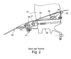
- the Fig. 2 shows in a simplified axial section view of a filling element according to the prior art and the attachment of the filling element.
- the Fig. 2 shows in particular an inlet cone 25 which is attached to a front retaining ring 37. To cover the attachment area, a front annular trim 38 is provided.
- a fan disk 29 carries distributed around the circumference of several fan blades, which (s. Fig. 1 ) form a gap 30. This gap 30 is closed by means of filling elements 33.
- a sealing washer 32 is arranged.
- the fan disk 29 is provided with a plurality of circumferentially distributed hooks 39, in which fastening hooks 40 are inserted, which are formed on the individual filling elements 33.
- the filling elements are made of aluminum, for example.
- the front portion of the filling elements 33 is fastened by means of a screw 41 to the front retaining ring 37 in order to prevent disengagement of the hooks 39 and the fastening hooks 40.
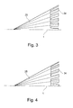
- the 3 and 4 each show a side view in a greatly simplified representation of an inlet cone 25, which is formed extended at its rear (seen in the flow direction) end and evenly distributed around the circumference has a plurality of lugs 34. These are preferably made by milling and are dimensioned so that they can be inserted into the interstices 30 of the fan 12 between the fan blades 31 when the inlet cone 25 is mounted.
- the two embodiments show different contouring of the projections 34 with angular or rounded base regions.
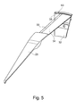
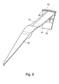
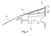
- Fig. 5 and 6 show in perspective parts of the inlet cone 25 with the lugs 34, which in a still in connection with Fig. 7 to be explained annular groove 35 of a sealing washer 32 are inserted or mounted.
- the Fig. 7 shows a simplified sectional view, analog Fig. 2 , It can be seen in particular that the strip-shaped projections 34 are integrally connected to the inlet cone 25. At their rear end region in the flow direction, the lugs 34 each have an insertion projection 36, which can be inserted or suspended in an annular groove 35 of the sealing disk 32.
- the annular groove 35 may be formed as a closed or radially open annular groove, in the latter area (s. Fig. 7 ), the annular groove 35 is formed in particular by a ring lip 43.
- Fig. 7 shows further that the lugs 34 are provided on its underside with a reinforcing region 42 which extends in a strip-shaped or rib-shaped manner in the longitudinal direction.
- a reinforcing region 42 which extends in a strip-shaped or rib-shaped manner in the longitudinal direction.
- the 10 and 11 each show sectional views along the line AA of Fig. 8 , wherein the dimensional representation is greatly simplified.
- the projection 34 can be screwed, riveted or connected by means of another bolt connection or the like with the filling element 33.
- the Fig. 11 schematically shows a representation in which the filling element 33 can be attached by means of laterally attached to the filling element 33 brackets or projections 44 on the neck 34 and positively held.
- FIG. 12 show modified embodiments of the lugs 34 and the gain regions 42 analog Fig. 7 ,
- a lesser distance results between the reinforcing region 42 and the fan disk 29; a front part of the reinforcing region 42 bears against the fan disk 29.
- Fig. 13 is the gain region 42 at full length on the fan disk 29 at.
- the invention thus describes a lightweight construction of the filling elements 33, in which they are not attached to the fan plate 29, but are attached to the lugs 34. In terms of manufacturing technology, therefore, the production of the hooks on the fan disk 29 is eliminated. Furthermore, both the fan disk 29 and the filling elements 33 can be made geometrically highly simplified and therefore lighter in weight and less expensive to manufacture. With regard to the sealing disc 32, no or only minor modifications are required, since it is only necessary to incorporate the annular groove 35 or the annular lip. The inlet cone 29 requires essentially no design changes.
- the filling elements Due to the low weight of the filling elements, the consequential damage to the gas turbine engine in case of failure of the filling elements are low. Another advantage is that the filling elements can be easily replaced after removing the inlet cone.
Landscapes
- Engineering & Computer Science (AREA)
- Mechanical Engineering (AREA)
- General Engineering & Computer Science (AREA)
- Chemical & Material Sciences (AREA)
- Combustion & Propulsion (AREA)
- Structures Of Non-Positive Displacement Pumps (AREA)
Applications Claiming Priority (1)
| Application Number | Priority Date | Filing Date | Title |
|---|---|---|---|
| DE102014217887.8A DE102014217887A1 (de) | 2014-09-08 | 2014-09-08 | Füllelemente eines Fans einer Gasturbine |
Publications (2)
| Publication Number | Publication Date |
|---|---|
| EP2993305A1 true EP2993305A1 (fr) | 2016-03-09 |
| EP2993305B1 EP2993305B1 (fr) | 2019-07-10 |
Family
ID=54007551
Family Applications (1)
| Application Number | Title | Priority Date | Filing Date |
|---|---|---|---|
| EP15182031.3A Not-in-force EP2993305B1 (fr) | 2014-09-08 | 2015-08-21 | Turbine a gaz |
Country Status (3)
| Country | Link |
|---|---|
| US (1) | US9664069B2 (fr) |
| EP (1) | EP2993305B1 (fr) |
| DE (1) | DE102014217887A1 (fr) |
Cited By (1)
| Publication number | Priority date | Publication date | Assignee | Title |
|---|---|---|---|---|
| CN108884720A (zh) * | 2016-03-21 | 2018-11-23 | 赛峰飞机发动机公司 | 航空涡轮发动机的叶片平台和风扇盘 |
Families Citing this family (2)
| Publication number | Priority date | Publication date | Assignee | Title |
|---|---|---|---|---|
| GB201813236D0 (en) * | 2018-08-14 | 2018-09-26 | Rolls Royce Plc | Windage shield |
| FR3126964B1 (fr) * | 2021-09-13 | 2023-08-04 | Safran Nacelles | Nacelle pour ensemble propulsif d’aéronef comprenant un espace d’accès obturé par un capotage à serrage tangentiel |
Citations (6)
| Publication number | Priority date | Publication date | Assignee | Title |
|---|---|---|---|---|
| US5067877A (en) * | 1990-09-11 | 1991-11-26 | United Technologies Corporation | Fan blade axial retention device |
| GB2363170A (en) | 2000-06-08 | 2001-12-12 | Rolls Royce Plc | Attaching a nose cone to a gas turbine engine rotor |
| FR2918409A1 (fr) * | 2007-07-05 | 2009-01-09 | Snecma Sa | Partie tournante de turbomachine comprenant des secteurs inter-aubes formant plateforme rapportes fixement sur un disque |
| EP2028375A2 (fr) * | 2007-08-24 | 2009-02-25 | Snecma | Soufflante pour turbomachine d'aéronef comprenant une bride d'équilibrage masquée par le cône d'entrée |
| FR2988426A1 (fr) * | 2012-03-20 | 2013-09-27 | Snecma | Plate-forme inter-aubes |
| WO2014105668A1 (fr) * | 2012-12-28 | 2014-07-03 | United Technologies Corporation | Structure d'attachement de nez de moteur de turbine à gaz |
Family Cites Families (3)
| Publication number | Priority date | Publication date | Assignee | Title |
|---|---|---|---|---|
| GB0910752D0 (en) * | 2009-06-23 | 2009-08-05 | Rolls Royce Plc | An annulus filler for a gas turbine engine |
| FR2960589B1 (fr) * | 2010-05-28 | 2014-05-02 | Snecma | Roue a aubes pour une turbomachine, telle qu'un turboreacteur ou un turbopropulseur d'avion |
| US9267386B2 (en) * | 2012-06-29 | 2016-02-23 | United Technologies Corporation | Fairing assembly |
-
2014
- 2014-09-08 DE DE102014217887.8A patent/DE102014217887A1/de not_active Withdrawn
-
2015
- 2015-08-21 EP EP15182031.3A patent/EP2993305B1/fr not_active Not-in-force
- 2015-09-02 US US14/843,459 patent/US9664069B2/en not_active Expired - Fee Related
Patent Citations (6)
| Publication number | Priority date | Publication date | Assignee | Title |
|---|---|---|---|---|
| US5067877A (en) * | 1990-09-11 | 1991-11-26 | United Technologies Corporation | Fan blade axial retention device |
| GB2363170A (en) | 2000-06-08 | 2001-12-12 | Rolls Royce Plc | Attaching a nose cone to a gas turbine engine rotor |
| FR2918409A1 (fr) * | 2007-07-05 | 2009-01-09 | Snecma Sa | Partie tournante de turbomachine comprenant des secteurs inter-aubes formant plateforme rapportes fixement sur un disque |
| EP2028375A2 (fr) * | 2007-08-24 | 2009-02-25 | Snecma | Soufflante pour turbomachine d'aéronef comprenant une bride d'équilibrage masquée par le cône d'entrée |
| FR2988426A1 (fr) * | 2012-03-20 | 2013-09-27 | Snecma | Plate-forme inter-aubes |
| WO2014105668A1 (fr) * | 2012-12-28 | 2014-07-03 | United Technologies Corporation | Structure d'attachement de nez de moteur de turbine à gaz |
Cited By (3)
| Publication number | Priority date | Publication date | Assignee | Title |
|---|---|---|---|---|
| CN108884720A (zh) * | 2016-03-21 | 2018-11-23 | 赛峰飞机发动机公司 | 航空涡轮发动机的叶片平台和风扇盘 |
| US11021973B2 (en) | 2016-03-21 | 2021-06-01 | Safran Aircraft Engines | Blade platform and a fan disk for an aviation turbine engine |
| CN108884720B (zh) * | 2016-03-21 | 2021-11-02 | 赛峰飞机发动机公司 | 航空涡轮发动机的叶片平台和风扇盘 |
Also Published As
| Publication number | Publication date |
|---|---|
| DE102014217887A1 (de) | 2016-03-10 |
| US20160069217A1 (en) | 2016-03-10 |
| US9664069B2 (en) | 2017-05-30 |
| EP2993305B1 (fr) | 2019-07-10 |
Similar Documents
| Publication | Publication Date | Title |
|---|---|---|
| EP2161431B1 (fr) | Cône d'entrée d'une turbine à gaz pour aéronef | |
| DE10210866C1 (de) | Leitschaufelbefestigung in einem Strömungskanal einer Fluggasturbine | |
| EP3034788B1 (fr) | Aube de compresseur d'une turbine a gaz | |
| EP2693061B1 (fr) | Aube de compresseur d'une turbine à gaz et son procédé de fabrication | |
| DE102012201050B4 (de) | Dichtungsanordnung, Verfahren sowie Strömungsmaschine | |
| DE102013223258A1 (de) | Brennkammerhitzeabschirmelement einer Gasturbine | |
| EP2268902B1 (fr) | Entretoise pour carter intermédiaire de turbine et carter intermédiaire de turbine | |
| DE102014204466A1 (de) | Brennkammer einer Gasturbine | |
| EP2356319A1 (fr) | Dispositif d'aubes directrices pour turbomachine axiale | |
| DE102014213302A1 (de) | Brennkammer einer Gasturbine mit verschraubtem Brennkammerkopf | |
| EP2993305B1 (fr) | Turbine a gaz | |
| DE102012000890A1 (de) | Befestigungselement und Enteisungsvorrichtung eines Fluggasturbinentriebwerks | |
| EP3176386B1 (fr) | Système de virole interne, virole interne, boîtier intermédiaire et turbomachine associés | |
| EP2526263B1 (fr) | Système de boîtier pour une turbomachine axiale | |
| DE102016215807A1 (de) | Innenring für einen Leitschaufelkranz einer Strömungsmaschine | |
| EP2998515B1 (fr) | Élements de remplissage d'un ventilateur d'une turbine a gaz | |
| DE102015225107A1 (de) | Gasturbinenbrennkammer mit Schindelbefestigung mittels Rastelementen | |
| EP2884051A1 (fr) | Rotor de turbomachine, turbomachine, compresseur axial, turbine à gaz et procédé de fabrication d'un rotor de turbomachine | |
| DE102014222320A1 (de) | Brennkammerwand einer Gasturbine mit Kühlung für einen Mischluftlochrand | |
| DE102017201349A1 (de) | Brennkammeranordnung einer Gasturbine | |
| DE102014219063A1 (de) | Konzentrische Bauteilanordnung einer Gasturbine | |
| DE102015224990A1 (de) | Verfahren zur Montage einer Brennkammer eines Gasturbinentriebwerks | |
| EP3009648B1 (fr) | Dispositif d'inversion de poussee de turbine a gaz volatile equipe d'un rail de guidage | |
| EP3022395B1 (fr) | Elément d'insertion et turbine à gaz | |
| EP3023598B1 (fr) | Élément déflecteur d'air entièrement intégré |
Legal Events
| Date | Code | Title | Description |
|---|---|---|---|
| PUAI | Public reference made under article 153(3) epc to a published international application that has entered the european phase |
Free format text: ORIGINAL CODE: 0009012 |
|
| AK | Designated contracting states |
Kind code of ref document: A1 Designated state(s): AL AT BE BG CH CY CZ DE DK EE ES FI FR GB GR HR HU IE IS IT LI LT LU LV MC MK MT NL NO PL PT RO RS SE SI SK SM TR |
|
| AX | Request for extension of the european patent |
Extension state: BA ME |
|
| 17P | Request for examination filed |
Effective date: 20160803 |
|
| RBV | Designated contracting states (corrected) |
Designated state(s): AL AT BE BG CH CY CZ DE DK EE ES FI FR GB GR HR HU IE IS IT LI LT LU LV MC MK MT NL NO PL PT RO RS SE SI SK SM TR |
|
| REG | Reference to a national code |
Ref country code: DE Ref legal event code: R079 Ref document number: 502015009580 Country of ref document: DE Free format text: PREVIOUS MAIN CLASS: F01D0005300000 Ipc: F01D0025280000 |
|
| GRAP | Despatch of communication of intention to grant a patent |
Free format text: ORIGINAL CODE: EPIDOSNIGR1 |
|
| STAA | Information on the status of an ep patent application or granted ep patent |
Free format text: STATUS: GRANT OF PATENT IS INTENDED |
|
| INTG | Intention to grant announced |
Effective date: 20190222 |
|
| RIC1 | Information provided on ipc code assigned before grant |
Ipc: F01D 5/32 20060101ALI20190208BHEP Ipc: F01D 5/30 20060101ALI20190208BHEP Ipc: F02C 7/04 20060101ALI20190208BHEP Ipc: F01D 9/02 20060101ALI20190208BHEP Ipc: F01D 5/12 20060101ALI20190208BHEP Ipc: F01D 25/28 20060101AFI20190208BHEP Ipc: F01D 11/00 20060101ALI20190208BHEP Ipc: F01D 5/02 20060101ALI20190208BHEP |
|
| GRAS | Grant fee paid |
Free format text: ORIGINAL CODE: EPIDOSNIGR3 |
|
| GRAA | (expected) grant |
Free format text: ORIGINAL CODE: 0009210 |
|
| STAA | Information on the status of an ep patent application or granted ep patent |
Free format text: STATUS: THE PATENT HAS BEEN GRANTED |
|
| AK | Designated contracting states |
Kind code of ref document: B1 Designated state(s): AL AT BE BG CH CY CZ DE DK EE ES FI FR GB GR HR HU IE IS IT LI LT LU LV MC MK MT NL NO PL PT RO RS SE SI SK SM TR |
|
| REG | Reference to a national code |
Ref country code: GB Ref legal event code: FG4D Free format text: NOT ENGLISH |
|
| REG | Reference to a national code |
Ref country code: CH Ref legal event code: EP Ref country code: AT Ref legal event code: REF Ref document number: 1153786 Country of ref document: AT Kind code of ref document: T Effective date: 20190715 |
|
| REG | Reference to a national code |
Ref country code: DE Ref legal event code: R096 Ref document number: 502015009580 Country of ref document: DE |
|
| REG | Reference to a national code |
Ref country code: IE Ref legal event code: FG4D Free format text: LANGUAGE OF EP DOCUMENT: GERMAN |
|
| REG | Reference to a national code |
Ref country code: NL Ref legal event code: MP Effective date: 20190710 |
|
| REG | Reference to a national code |
Ref country code: LT Ref legal event code: MG4D |
|
| PG25 | Lapsed in a contracting state [announced via postgrant information from national office to epo] |
Ref country code: LT Free format text: LAPSE BECAUSE OF FAILURE TO SUBMIT A TRANSLATION OF THE DESCRIPTION OR TO PAY THE FEE WITHIN THE PRESCRIBED TIME-LIMIT Effective date: 20190710 Ref country code: HR Free format text: LAPSE BECAUSE OF FAILURE TO SUBMIT A TRANSLATION OF THE DESCRIPTION OR TO PAY THE FEE WITHIN THE PRESCRIBED TIME-LIMIT Effective date: 20190710 Ref country code: NL Free format text: LAPSE BECAUSE OF FAILURE TO SUBMIT A TRANSLATION OF THE DESCRIPTION OR TO PAY THE FEE WITHIN THE PRESCRIBED TIME-LIMIT Effective date: 20190710 Ref country code: PT Free format text: LAPSE BECAUSE OF FAILURE TO SUBMIT A TRANSLATION OF THE DESCRIPTION OR TO PAY THE FEE WITHIN THE PRESCRIBED TIME-LIMIT Effective date: 20191111 Ref country code: SE Free format text: LAPSE BECAUSE OF FAILURE TO SUBMIT A TRANSLATION OF THE DESCRIPTION OR TO PAY THE FEE WITHIN THE PRESCRIBED TIME-LIMIT Effective date: 20190710 Ref country code: BG Free format text: LAPSE BECAUSE OF FAILURE TO SUBMIT A TRANSLATION OF THE DESCRIPTION OR TO PAY THE FEE WITHIN THE PRESCRIBED TIME-LIMIT Effective date: 20191010 Ref country code: NO Free format text: LAPSE BECAUSE OF FAILURE TO SUBMIT A TRANSLATION OF THE DESCRIPTION OR TO PAY THE FEE WITHIN THE PRESCRIBED TIME-LIMIT Effective date: 20191010 Ref country code: FI Free format text: LAPSE BECAUSE OF FAILURE TO SUBMIT A TRANSLATION OF THE DESCRIPTION OR TO PAY THE FEE WITHIN THE PRESCRIBED TIME-LIMIT Effective date: 20190710 |
|
| PG25 | Lapsed in a contracting state [announced via postgrant information from national office to epo] |
Ref country code: RS Free format text: LAPSE BECAUSE OF FAILURE TO SUBMIT A TRANSLATION OF THE DESCRIPTION OR TO PAY THE FEE WITHIN THE PRESCRIBED TIME-LIMIT Effective date: 20190710 Ref country code: IS Free format text: LAPSE BECAUSE OF FAILURE TO SUBMIT A TRANSLATION OF THE DESCRIPTION OR TO PAY THE FEE WITHIN THE PRESCRIBED TIME-LIMIT Effective date: 20191110 Ref country code: ES Free format text: LAPSE BECAUSE OF FAILURE TO SUBMIT A TRANSLATION OF THE DESCRIPTION OR TO PAY THE FEE WITHIN THE PRESCRIBED TIME-LIMIT Effective date: 20190710 Ref country code: GR Free format text: LAPSE BECAUSE OF FAILURE TO SUBMIT A TRANSLATION OF THE DESCRIPTION OR TO PAY THE FEE WITHIN THE PRESCRIBED TIME-LIMIT Effective date: 20191011 Ref country code: LV Free format text: LAPSE BECAUSE OF FAILURE TO SUBMIT A TRANSLATION OF THE DESCRIPTION OR TO PAY THE FEE WITHIN THE PRESCRIBED TIME-LIMIT Effective date: 20190710 Ref country code: AL Free format text: LAPSE BECAUSE OF FAILURE TO SUBMIT A TRANSLATION OF THE DESCRIPTION OR TO PAY THE FEE WITHIN THE PRESCRIBED TIME-LIMIT Effective date: 20190710 |
|
| PG25 | Lapsed in a contracting state [announced via postgrant information from national office to epo] |
Ref country code: TR Free format text: LAPSE BECAUSE OF FAILURE TO SUBMIT A TRANSLATION OF THE DESCRIPTION OR TO PAY THE FEE WITHIN THE PRESCRIBED TIME-LIMIT Effective date: 20190710 |
|
| PG25 | Lapsed in a contracting state [announced via postgrant information from national office to epo] |
Ref country code: DK Free format text: LAPSE BECAUSE OF FAILURE TO SUBMIT A TRANSLATION OF THE DESCRIPTION OR TO PAY THE FEE WITHIN THE PRESCRIBED TIME-LIMIT Effective date: 20190710 Ref country code: PL Free format text: LAPSE BECAUSE OF FAILURE TO SUBMIT A TRANSLATION OF THE DESCRIPTION OR TO PAY THE FEE WITHIN THE PRESCRIBED TIME-LIMIT Effective date: 20190710 Ref country code: EE Free format text: LAPSE BECAUSE OF FAILURE TO SUBMIT A TRANSLATION OF THE DESCRIPTION OR TO PAY THE FEE WITHIN THE PRESCRIBED TIME-LIMIT Effective date: 20190710 Ref country code: RO Free format text: LAPSE BECAUSE OF FAILURE TO SUBMIT A TRANSLATION OF THE DESCRIPTION OR TO PAY THE FEE WITHIN THE PRESCRIBED TIME-LIMIT Effective date: 20190710 Ref country code: IT Free format text: LAPSE BECAUSE OF FAILURE TO SUBMIT A TRANSLATION OF THE DESCRIPTION OR TO PAY THE FEE WITHIN THE PRESCRIBED TIME-LIMIT Effective date: 20190710 |
|
| PG25 | Lapsed in a contracting state [announced via postgrant information from national office to epo] |
Ref country code: IS Free format text: LAPSE BECAUSE OF FAILURE TO SUBMIT A TRANSLATION OF THE DESCRIPTION OR TO PAY THE FEE WITHIN THE PRESCRIBED TIME-LIMIT Effective date: 20200224 Ref country code: LU Free format text: LAPSE BECAUSE OF NON-PAYMENT OF DUE FEES Effective date: 20190821 Ref country code: SM Free format text: LAPSE BECAUSE OF FAILURE TO SUBMIT A TRANSLATION OF THE DESCRIPTION OR TO PAY THE FEE WITHIN THE PRESCRIBED TIME-LIMIT Effective date: 20190710 Ref country code: SK Free format text: LAPSE BECAUSE OF FAILURE TO SUBMIT A TRANSLATION OF THE DESCRIPTION OR TO PAY THE FEE WITHIN THE PRESCRIBED TIME-LIMIT Effective date: 20190710 Ref country code: MC Free format text: LAPSE BECAUSE OF FAILURE TO SUBMIT A TRANSLATION OF THE DESCRIPTION OR TO PAY THE FEE WITHIN THE PRESCRIBED TIME-LIMIT Effective date: 20190710 Ref country code: CZ Free format text: LAPSE BECAUSE OF FAILURE TO SUBMIT A TRANSLATION OF THE DESCRIPTION OR TO PAY THE FEE WITHIN THE PRESCRIBED TIME-LIMIT Effective date: 20190710 Ref country code: CH Free format text: LAPSE BECAUSE OF NON-PAYMENT OF DUE FEES Effective date: 20190831 Ref country code: LI Free format text: LAPSE BECAUSE OF NON-PAYMENT OF DUE FEES Effective date: 20190831 |
|
| REG | Reference to a national code |
Ref country code: BE Ref legal event code: MM Effective date: 20190831 |
|
| REG | Reference to a national code |
Ref country code: DE Ref legal event code: R097 Ref document number: 502015009580 Country of ref document: DE |
|
| PLBE | No opposition filed within time limit |
Free format text: ORIGINAL CODE: 0009261 |
|
| STAA | Information on the status of an ep patent application or granted ep patent |
Free format text: STATUS: NO OPPOSITION FILED WITHIN TIME LIMIT |
|
| PG2D | Information on lapse in contracting state deleted |
Ref country code: IS |
|
| PG25 | Lapsed in a contracting state [announced via postgrant information from national office to epo] |
Ref country code: IE Free format text: LAPSE BECAUSE OF NON-PAYMENT OF DUE FEES Effective date: 20190821 |
|
| 26N | No opposition filed |
Effective date: 20200603 |
|
| PG25 | Lapsed in a contracting state [announced via postgrant information from national office to epo] |
Ref country code: SI Free format text: LAPSE BECAUSE OF FAILURE TO SUBMIT A TRANSLATION OF THE DESCRIPTION OR TO PAY THE FEE WITHIN THE PRESCRIBED TIME-LIMIT Effective date: 20190710 Ref country code: BE Free format text: LAPSE BECAUSE OF NON-PAYMENT OF DUE FEES Effective date: 20190831 |
|
| PGFP | Annual fee paid to national office [announced via postgrant information from national office to epo] |
Ref country code: GB Payment date: 20200825 Year of fee payment: 6 Ref country code: FR Payment date: 20200824 Year of fee payment: 6 |
|
| PGFP | Annual fee paid to national office [announced via postgrant information from national office to epo] |
Ref country code: DE Payment date: 20201029 Year of fee payment: 6 |
|
| PG25 | Lapsed in a contracting state [announced via postgrant information from national office to epo] |
Ref country code: CY Free format text: LAPSE BECAUSE OF FAILURE TO SUBMIT A TRANSLATION OF THE DESCRIPTION OR TO PAY THE FEE WITHIN THE PRESCRIBED TIME-LIMIT Effective date: 20190710 |
|
| PG25 | Lapsed in a contracting state [announced via postgrant information from national office to epo] |
Ref country code: HU Free format text: LAPSE BECAUSE OF FAILURE TO SUBMIT A TRANSLATION OF THE DESCRIPTION OR TO PAY THE FEE WITHIN THE PRESCRIBED TIME-LIMIT; INVALID AB INITIO Effective date: 20150821 Ref country code: MT Free format text: LAPSE BECAUSE OF FAILURE TO SUBMIT A TRANSLATION OF THE DESCRIPTION OR TO PAY THE FEE WITHIN THE PRESCRIBED TIME-LIMIT Effective date: 20190710 |
|
| REG | Reference to a national code |
Ref country code: AT Ref legal event code: MM01 Ref document number: 1153786 Country of ref document: AT Kind code of ref document: T Effective date: 20200821 |
|
| PG25 | Lapsed in a contracting state [announced via postgrant information from national office to epo] |
Ref country code: AT Free format text: LAPSE BECAUSE OF NON-PAYMENT OF DUE FEES Effective date: 20200821 |
|
| REG | Reference to a national code |
Ref country code: DE Ref legal event code: R119 Ref document number: 502015009580 Country of ref document: DE |
|
| GBPC | Gb: european patent ceased through non-payment of renewal fee |
Effective date: 20210821 |
|
| PG25 | Lapsed in a contracting state [announced via postgrant information from national office to epo] |
Ref country code: MK Free format text: LAPSE BECAUSE OF FAILURE TO SUBMIT A TRANSLATION OF THE DESCRIPTION OR TO PAY THE FEE WITHIN THE PRESCRIBED TIME-LIMIT Effective date: 20190710 |
|
| PG25 | Lapsed in a contracting state [announced via postgrant information from national office to epo] |
Ref country code: GB Free format text: LAPSE BECAUSE OF NON-PAYMENT OF DUE FEES Effective date: 20210821 Ref country code: FR Free format text: LAPSE BECAUSE OF NON-PAYMENT OF DUE FEES Effective date: 20210831 Ref country code: DE Free format text: LAPSE BECAUSE OF NON-PAYMENT OF DUE FEES Effective date: 20220301 |