EP2993341B1 - Kraftstoffpumpe für ein direkteinspritzsystem - Google Patents
Kraftstoffpumpe für ein direkteinspritzsystem Download PDFInfo
- Publication number
- EP2993341B1 EP2993341B1 EP15184126.9A EP15184126A EP2993341B1 EP 2993341 B1 EP2993341 B1 EP 2993341B1 EP 15184126 A EP15184126 A EP 15184126A EP 2993341 B1 EP2993341 B1 EP 2993341B1
- Authority
- EP
- European Patent Office
- Prior art keywords
- turns
- actuating spring
- pitch
- fuel pump
- pumping chamber
- Prior art date
- Legal status (The legal status is an assumption and is not a legal conclusion. Google has not performed a legal analysis and makes no representation as to the accuracy of the status listed.)
- Active
Links
Images




Classifications
-
- F—MECHANICAL ENGINEERING; LIGHTING; HEATING; WEAPONS; BLASTING
- F02—COMBUSTION ENGINES; HOT-GAS OR COMBUSTION-PRODUCT ENGINE PLANTS
- F02M—SUPPLYING COMBUSTION ENGINES IN GENERAL WITH COMBUSTIBLE MIXTURES OR CONSTITUENTS THEREOF
- F02M63/00—Other fuel-injection apparatus having pertinent characteristics not provided for in groups F02M39/00 - F02M57/00 or F02M67/00; Details, component parts, or accessories of fuel-injection apparatus, not provided for in, or of interest apart from, the apparatus of groups F02M39/00 - F02M61/00 or F02M67/00; Combination of fuel pump with other devices, e.g. lubricating oil pump
- F02M63/02—Fuel-injection apparatus having several injectors fed by a common pumping element, or having several pumping elements feeding a common injector; Fuel-injection apparatus having provisions for cutting-out pumps, pumping elements, or injectors; Fuel-injection apparatus having provisions for variably interconnecting pumping elements and injectors alternatively
- F02M63/0225—Fuel-injection apparatus having a common rail feeding several injectors ; Means for varying pressure in common rails; Pumps feeding common rails
- F02M63/0265—Pumps feeding common rails
-
- F—MECHANICAL ENGINEERING; LIGHTING; HEATING; WEAPONS; BLASTING
- F02—COMBUSTION ENGINES; HOT-GAS OR COMBUSTION-PRODUCT ENGINE PLANTS
- F02M—SUPPLYING COMBUSTION ENGINES IN GENERAL WITH COMBUSTIBLE MIXTURES OR CONSTITUENTS THEREOF
- F02M59/00—Pumps specially adapted for fuel-injection and not provided for in groups F02M39/00 -F02M57/00, e.g. rotary cylinder-block type of pumps
- F02M59/02—Pumps specially adapted for fuel-injection and not provided for in groups F02M39/00 -F02M57/00, e.g. rotary cylinder-block type of pumps of reciprocating-piston or reciprocating-cylinder type
- F02M59/04—Pumps specially adapted for fuel-injection and not provided for in groups F02M39/00 -F02M57/00, e.g. rotary cylinder-block type of pumps of reciprocating-piston or reciprocating-cylinder type characterised by special arrangement of cylinders with respect to piston-driving shaft, e.g. arranged parallel to that shaft or swash-plate type pumps
- F02M59/06—Pumps specially adapted for fuel-injection and not provided for in groups F02M39/00 -F02M57/00, e.g. rotary cylinder-block type of pumps of reciprocating-piston or reciprocating-cylinder type characterised by special arrangement of cylinders with respect to piston-driving shaft, e.g. arranged parallel to that shaft or swash-plate type pumps with cylinders arranged radially to driving shaft, e.g. in V or star arrangement
-
- F—MECHANICAL ENGINEERING; LIGHTING; HEATING; WEAPONS; BLASTING
- F02—COMBUSTION ENGINES; HOT-GAS OR COMBUSTION-PRODUCT ENGINE PLANTS
- F02M—SUPPLYING COMBUSTION ENGINES IN GENERAL WITH COMBUSTIBLE MIXTURES OR CONSTITUENTS THEREOF
- F02M59/00—Pumps specially adapted for fuel-injection and not provided for in groups F02M39/00 -F02M57/00, e.g. rotary cylinder-block type of pumps
- F02M59/02—Pumps specially adapted for fuel-injection and not provided for in groups F02M39/00 -F02M57/00, e.g. rotary cylinder-block type of pumps of reciprocating-piston or reciprocating-cylinder type
- F02M59/10—Pumps specially adapted for fuel-injection and not provided for in groups F02M39/00 -F02M57/00, e.g. rotary cylinder-block type of pumps of reciprocating-piston or reciprocating-cylinder type characterised by the piston-drive
- F02M59/102—Mechanical drive, e.g. tappets or cams
-
- F—MECHANICAL ENGINEERING; LIGHTING; HEATING; WEAPONS; BLASTING
- F04—POSITIVE - DISPLACEMENT MACHINES FOR LIQUIDS; PUMPS FOR LIQUIDS OR ELASTIC FLUIDS
- F04B—POSITIVE-DISPLACEMENT MACHINES FOR LIQUIDS; PUMPS
- F04B1/00—Multi-cylinder machines or pumps characterised by number or arrangement of cylinders
- F04B1/04—Multi-cylinder machines or pumps characterised by number or arrangement of cylinders having cylinders in star- or fan-arrangement
- F04B1/0404—Details or component parts
- F04B1/0426—Arrangements for pressing the pistons against the actuated cam; Arrangements for connecting the pistons to the actuated cam
-
- F—MECHANICAL ENGINEERING; LIGHTING; HEATING; WEAPONS; BLASTING
- F04—POSITIVE - DISPLACEMENT MACHINES FOR LIQUIDS; PUMPS FOR LIQUIDS OR ELASTIC FLUIDS
- F04B—POSITIVE-DISPLACEMENT MACHINES FOR LIQUIDS; PUMPS
- F04B1/00—Multi-cylinder machines or pumps characterised by number or arrangement of cylinders
- F04B1/04—Multi-cylinder machines or pumps characterised by number or arrangement of cylinders having cylinders in star- or fan-arrangement
- F04B1/0404—Details or component parts
- F04B1/0452—Distribution members, e.g. valves
-
- F—MECHANICAL ENGINEERING; LIGHTING; HEATING; WEAPONS; BLASTING
- F04—POSITIVE - DISPLACEMENT MACHINES FOR LIQUIDS; PUMPS FOR LIQUIDS OR ELASTIC FLUIDS
- F04B—POSITIVE-DISPLACEMENT MACHINES FOR LIQUIDS; PUMPS
- F04B53/00—Component parts, details or accessories not provided for in, or of interest apart from, groups F04B1/00 - F04B23/00 or F04B39/00 - F04B47/00
- F04B53/10—Valves; Arrangement of valves
- F04B53/1002—Ball valves
-
- F—MECHANICAL ENGINEERING; LIGHTING; HEATING; WEAPONS; BLASTING
- F16—ENGINEERING ELEMENTS AND UNITS; GENERAL MEASURES FOR PRODUCING AND MAINTAINING EFFECTIVE FUNCTIONING OF MACHINES OR INSTALLATIONS; THERMAL INSULATION IN GENERAL
- F16F—SPRINGS; SHOCK-ABSORBERS; MEANS FOR DAMPING VIBRATION
- F16F1/00—Springs
- F16F1/02—Springs made of steel or other material having low internal friction; Wound, torsion, leaf, cup, ring or the like springs, the material of the spring not being relevant
- F16F1/04—Wound springs
- F16F1/047—Wound springs characterised by varying pitch
-
- F—MECHANICAL ENGINEERING; LIGHTING; HEATING; WEAPONS; BLASTING
- F02—COMBUSTION ENGINES; HOT-GAS OR COMBUSTION-PRODUCT ENGINE PLANTS
- F02M—SUPPLYING COMBUSTION ENGINES IN GENERAL WITH COMBUSTIBLE MIXTURES OR CONSTITUENTS THEREOF
- F02M2200/00—Details of fuel-injection apparatus, not otherwise provided for
- F02M2200/02—Fuel-injection apparatus having means for reducing wear
Definitions
- the present invention relates to a fuel pump for a direct injection system.
- a direct injection system comprises a plurality of injectors, a common rail that feeds the fuel under pressure to the injectors, a high-pressure fuel pump that feeds the fuel to the common rail through a high-pressure feeding conduit and is provided with a flow-rate-adjustment device, and a control unit that pilots the flow-rate-adjustment device for keeping the fuel pressure inside the common rail equal to a desired-value generally time-course variable as a function of the operating conditions of the engine.
- the high-pressure fuel pump described in patent application EP2236809A1 comprises a pumping chamber in which a piston slides with alternating motion, an intake channel regulated by a intake valve for feeding the low-pressure fuel inside the pumping chamber, and a delivery conduit regulated by a delivery valve for feeding the high-pressure fuel outside the pumping chamber and towards the common rail through the feeding conduit.
- a lower portion of the piston is coupled, on one side, to an actuating spring which tends to push the piston towards a position of maximum volume of the pumping chamber and, on the other side, is coupled to a cam that is set in rotation by the driving shaft to cyclically move the piston compressing the actuating spring.
- the high-pressure fuel pump described above has an adequately long operating life to fully satisfy the demands of durability of internal combustion engines manufacturers; however, it has been observed that towards the end of the expected operating life seizures of the piston may occur (i.e. locking of the piston due to excessive sliding friction).
- the patent US6145762A describes an electromagnetic fuel injector provided with a closing spring, which has a variable pitch between the turns for reducing wear due to fatigue of the closing spring.
- a closing spring with variable pitch between the turns serves to solve the problem of premature breakage due to usage caused by longitudinal oscillations of the closing spring from its natural oscillation frequency; when the pitch between the turns of the closing spring is variable, in case of resonance corresponding to a harmonic, the end turns open and close varying the natural oscillation frequency of the closing spring, and therefore pushing the closing spring out from the resonance (in this way, the spring does not oscillate from its natural oscillation frequency as the natural oscillation frequency is continuously variable).
- the patent application FR802008A describes a return spring for a valve of an internal combustion engine, in which the return spring has a variable pitch between the turns for reducing wear due to fatigue of the return spring.
- the wear due to fatigue of the return spring is amplified by vibratory phenomena that can be triggered in the return spring; in the event of the occurrence of vibratory phenomenon in the return spring, the ends of the return spring (having a reduced pitch between the turns) tend to come in mutual contact determining a vibration damping.
- the object of the present invention is to provide a fuel pump for a direct injection system, the fuel pump has an increased operating life and is both easy and inexpensive to produce.
- a fuel pump is provided for a direct injection system, as claimed by the appended claims.
- number 1 indicates as a whole a system for the direct injection of fuel of a common rail type for an internal combustion thermal engine.
- the direct injection system 1 comprises a plurality of injectors 2, a common rail 3 that feeds the pressurized fuel to the injectors 2, a high-pressure pump 4, which feeds the fuel to the common rail 3 by means of a feed conduit 5 and is provided with a flow-rate-adjustment device 6, a control unit 7 that keeps the fuel pressure inside the common rail 3 equal to a desired-value generally time-course variable as a function of the operating conditions of the engine, and a low-pressure pump 8 that feeds the fuel from a tank 9 to the high-pressure pump 4 by means of a feed conduit 10.
- the control unit 7 is coupled to the flow-rate-adjustment device 6 to control the flow rate of the high-pressure pump 4 so as to feed the common rail 3, instant by instant, with the amount of fuel necessary to obtain the desired pressure value inside the common rail 3; in particular, the control unit 7 regulates the flow rate of the high-pressure pump 4 by means of a feedback control using as variable feedback the value of the fuel pressure inside the common rail 3, pressure value detected in real time by a pressure sensor 11.
- the high-pressure pump 4 comprises a main body 12 which has a longitudinal axis 13 and defines in its inside a cylindrical-shaped pumping chamber 14. Inside the pumping chamber 14 a piston 15 is mounted in a sliding manner which by moving with a reciprocating motion along the longitudinal axis 13 causes a cyclic variation of the volume of the pumping chamber 14. A lower portion of the piston 15 is coupled, on one side, to an actuating spring 16 which tends to push the piston 15 towards a position of maximum volume of the pumping chamber 14 and, the other side, is coupled to a cam (not illustrated) which is set in rotation by the drive shaft to cyclically move the piston 15 upwards compressing the actuating spring 16.
- the actuating spring 16 instead of pushing the piston 15 towards a position of maximum volume of the pumping chamber 14, pushes the piston 15 towards a position of minimum volume of the pumping chamber 14.
- an intake channel 17 originates which is connected to the low-pressure pump 8 by means of the supply conduit 10 and is regulated by an intake valve 18 arranged at the pumping chamber 14.
- the intake valve 18 is normally controlled under pressure and should no external intervention occur the intake valve 18 is closed when the fuel pressure in the pumping chamber 14 is higher than the fuel pressure in the intake channel 17 and is open when the fuel pressure in the pumping chamber 14 is lower than the fuel pressure in the intake channel 17.
- a delivery channel 19 originates which is connected to the common rail 3 by means of the feed conduit 5 and is regulated by an unidirectional delivery valve 20 which is arranged at the pumping chamber 14 and allows only an outgoing fuel flow from the pumping chamber 14.
- the delivery valve 20 is controlled under pressure and is open when the fuel pressure in the pumping chamber 14 is higher than the fuel pressure in the delivery channel 19 and is closed when the fuel pressure in the pumping chamber 14 is lower than the fuel pressure in the delivery channel 19.
- the flow-rate-adjustment device 6 is mechanically coupled to the intake valve 18 enabling the control unit 7 to keep, when necessary, the intake valve 18 open during a pumping phase of the piston 15 and then allow a fuel flow outgoing from the pumping chamber 14 through the intake channel 17.
- a collecting chamber 21 is formed, which is arranged below the pumping chamber 14, is crossed by an intermediate portion of the piston 15 which is shaped so as to cyclically vary the volume of the collecting chamber 21 by the effect of its reciprocating movement and is connected to the intake channel 17 by means of a connecting channel 22 opening into the intake valve 18.
- a gasket 23 of annular seal is provided, which is arranged about a lower portion of the piston 15 and has the function of preventing leakages of fuel along the lateral wall of the piston 15.
- the collecting chamber 21 is delimited at the top and laterally by a lower surface of the main body 12 and is delimited at the bottom by an annular cap 24 which is laterally welded to the main body 12.
- the actuating spring 16 is compressed between a lower wall of the annular cap 24 and an upper wall of an annular expansion 25 integral with the lower end of the piston 15; in this way, the actuating spring 16 is arranged outside the main body 12 and is therefore both visually inspectable, and fully isolated from the fuel.
- the cam (not shown) that is set in rotation by the drive shaft of the motor rests on the piston 15 from the opposite side of the actuating spring 16 to move the piston 15 cyclically upwards, compressing the actuating spring 16.
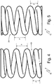
- the actuating spring 16 is a helical compression spring comprising a plurality of open turns 26 that are wound and dimensioned to exert compression along the axis of the actuating spring 16.
- the actuating spring 16 is cylindrical shaped, and therefore maintains the same outer diameter throughout its entire length.
- the two end turns 26, i.e. the two turns 26 arranged at the opposite ends of the actuating spring 16 which rest respectively on the annular cap 24 and at the annular expansion 25, are dead, i.e.
- the dead (end) turns 26 are instead all active, i.e. all contribute to generating the elastic force when the actuating spring 16 is compressed.
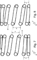
- the actuating spring 16 has, along its length, a pitch P between the turns 26 (i.e. an average distance between two contiguous turns 26) that is variable so that at least at one end of the actuating spring 16 the pitch P between the turns 26 is smaller than the pitch P between the turns 26 at a central portion.
- the pitch P between the turns 26 is variable so that at each cycle of the piston 15 a part and only a part of the turns 26 pack-tighten together determining a change of the application direction of the lateral load generated by the actuating spring 16 limiting the maximum value of the lateral load.
- the pitch P between the turns 26 is smaller than the pitch P between the turns 26 at the central portion; in particular, the pitch P between the turns 26 is identical at both ends of the actuating spring 16.
- the pitch P between the turns 26 ranges from 1.2 and 2.2 times (and preferably between 1.4 and 2.0 times) the pitch P between the turns 26 at the ends of the actuating spring 16.
- the actuating spring 16 is manufactured in a mirror-like manner relative to a transverse symmetry plane arranged at the center.
- the actuating spring 16 comprises a total of (i.e. counting both the active turns 26, and the dead ends turns 26) 5.6 turns; more generally, the actuating spring 16 may comprise a total number of turns 26 between 4.5 and 7.5.
- the actuating spring 16 when the actuating spring 16 is compressed the actuating spring 16 generates both an axial load (thrust) (i.e. directed parallel to the central axis of symmetry), and a lateral load (thrust) (i.e. directed perpendicular to the central axis of symmetry); the axial load (thrust) is useful (desired), that constitutes the function of the actuating spring 16 and is required to properly move the piston 15, while the lateral load (thrust) is damaging (unwanted) since the piston 15 is subjected to radial stress that generate increased wear of the piston 15 (that is both the outer surface of the piston 15, and the inner surface of the cavity along which the piston 15 slides are worn out).
- a pitch P between the turns 26 shorter at the opposite ends of the actuating spring 16 it is possible to significantly reduce the lateral load (thrust) at the same axial load (thrust).
- the high-pressure pump 4 described above has numerous advantages.
- the high-pressure pump 4 described above has an increased operating life thanks to the reduced possibility of the jamming of the piston 15.
- This result is obtained using an actuating spring 16 which shows as a whole a reduced lateral load (thrust) which then subjects the piston 15 to lesser wear.
- the high-pressure pump 4 as described above is simple and inexpensive to produce, since the production and assembly costs of the actuating spring 16 described above are virtually completely identical to the production and assembly costs of a standard actuating spring.
Landscapes
- Engineering & Computer Science (AREA)
- General Engineering & Computer Science (AREA)
- Mechanical Engineering (AREA)
- Chemical & Material Sciences (AREA)
- Combustion & Propulsion (AREA)
- Fuel-Injection Apparatus (AREA)
Claims (9)
- Kraftstoffpumpe (4) für ein Direkteinspritzsystem, das mit einem Kraftstoffspeicher (3) versehen ist; welche Kraftstoffpumpe (4) enthält:eine Pumpenkammer (14), die in einem Hauptkörper (12) gebildet ist;einen Kolben (15), der in verschiebbarer Weise innerhalb der Pumpenkammer (14) angebracht ist, so dass er das Volumen der Pumpenkammer (14) zyklisch variiert;einen Einlasskanal (17), der von einer Wand der Pumpenkammer (14) ausgeht;ein Einlassventil (18), das mit dem Einlasskanal (17) verbunden ist;einen Abgabekanal (19), der von einer Wand der Pumpenkammer (14) ausgeht;ein Abgabeventil (20), das mit dem Abgabekanal (19) verbunden ist; undeine Betätigungsfeder (16), die eine Vielzahl von Windungen (26) aufweist und mit dem Kolben (15) dergestalt gekoppelt ist, dass sie den Kolben (15) in Richtung einer Position des größten Volumens oder des kleinsten Volumens der Pumpenkammer (14) verschiebt;welche Kraftstoffpumpe (4) dadurch gekennzeichnet ist, dass die Betätigungsfeder (16) über ihre Länge eine Teilung (P) zwischen den Windungen (26) hat, die so variabel ist, dass bei jedem Zyklus des Kolbens (15) ein Teil und nur ein Teil der Windungen (26) zur Anlage aneinander kommt und dabei eine Veränderung der Anlegungsrichtung der von der Betätigungsfeder (16) erzeugten seitlichen Last bestimmt, um den Maximalwert der seitlichen Last zu begrenzen.
- Kraftstoffpumpe (4) nach Anspruch 1, wobei mindestens an einem Ende der Betätigungsfeder (16) die Teilung (P) zwischen den Windungen (26) kleiner ist als die Teilung (P) zwischen den Windungen (26) in einem mittleren Teil.
- Kraftstoffpumpe (4) nach Anspruch 2, wobei an beiden Enden der Betätigungsfeder (16) die Teilung (P) zwischen den Windungen (26) kleiner ist als die Teilung (P) zwischen den Windungen (26) in einem mittleren Teil.
- Kraftstoffpumpe (4) nach Anspruch 3, wobei die Teilung (P) zwischen den Windungen (26) an beiden Enden der Betätigungsfeder (16) identisch ist.
- Kraftstoffpumpe (4) nach Anspruch 2, 3 oder 4, wobei in einem mittleren Teil die Teilung (P) zwischen den Windungen (26) im Bereich vom 1,2- bis zum 2,2-fachen der Teilung (P) zwischen den Windungen (26) an mindestens einem Ende der Betätigungsfeder (16) liegt.
- Kraftstoffpumpe (4) nach Anspruch 2, 3 oder 4, wobei in einem mittleren Teil die Teilung (P) zwischen den Windungen (26) im Bereich vom 1,4- bis zum 2,0-fachen der Teilung (P) zwischen den Windungen (26) an mindestens einem Ende der Betätigungsfeder (16) liegt.
- Kraftstoffpumpe (4) nach einem der Ansprüche von 1 bis 6, wobei die Betätigungsfeder (16) zwei Totwindungen (26) an den entgegengesetzten Enden der Betätigungsfeder (16) aufweist.
- Kraftstoffpumpe (4) nach einem der Ansprüche von 1 bis 7, wobei die Betätigungsfeder (16) insgesamt eine Anzahl von Windungen (26) im Bereich von 4,5 bis 7,5 aufweist.
- Kraftstoffpumpe (4) nach einem der Ansprüche von 1 bis 8, wobei die Betätigungsfeder (16) in spiegelbildlicher Weise in Bezug auf eine in der Mitte angeordnete Quersymmetrieebene hergestellt ist.
Applications Claiming Priority (1)
| Application Number | Priority Date | Filing Date | Title |
|---|---|---|---|
| ITBO20140493 | 2014-09-08 |
Publications (2)
| Publication Number | Publication Date |
|---|---|
| EP2993341A1 EP2993341A1 (de) | 2016-03-09 |
| EP2993341B1 true EP2993341B1 (de) | 2017-03-29 |
Family
ID=51753289
Family Applications (1)
| Application Number | Title | Priority Date | Filing Date |
|---|---|---|---|
| EP15184126.9A Active EP2993341B1 (de) | 2014-09-08 | 2015-09-07 | Kraftstoffpumpe für ein direkteinspritzsystem |
Country Status (3)
| Country | Link |
|---|---|
| US (1) | US9822751B2 (de) |
| EP (1) | EP2993341B1 (de) |
| CN (1) | CN105464867B (de) |
Families Citing this family (3)
| Publication number | Priority date | Publication date | Assignee | Title |
|---|---|---|---|---|
| DE102015215186B3 (de) * | 2015-08-10 | 2016-12-15 | Continental Automotive Gmbh | Kraftstoffhochdruckpumpe |
| JP6535131B2 (ja) * | 2016-03-31 | 2019-06-26 | 日本発條株式会社 | コイルばね |
| DE102017205388A1 (de) * | 2017-03-30 | 2018-10-04 | Robert Bosch Gmbh | Stößelbaugruppe für eine Radialkolbenpumpe, Radialkolbenpumpe |
Family Cites Families (15)
| Publication number | Priority date | Publication date | Assignee | Title |
|---|---|---|---|---|
| FR802008A (fr) | 1935-05-09 | 1936-08-25 | Ressort | |
| DE3713288A1 (de) * | 1986-07-25 | 1988-02-04 | Man Nutzfahrzeuge Gmbh | Steuereinrichtung fuer die verstellung des einspritzzeitpunktes und/oder der foerdermenge einer kraftstoffeinspritzpumpe |
| US6145762A (en) | 1998-10-19 | 2000-11-14 | Cummins Engine Company, Inc. | Variable rate spring for a fuel injector |
| DE19905790A1 (de) * | 1999-02-12 | 2000-08-17 | Bosch Gmbh Robert | Kolbenpumpe |
| GB0005825D0 (en) * | 2000-03-11 | 2000-05-03 | Archfact Ltd | Compressor spring locator |
| DE102004013307B4 (de) * | 2004-03-17 | 2012-12-06 | Robert Bosch Gmbh | Kraftstoffhochdruckpumpe mit einem Druckbegrenzungsventil |
| JP2006207451A (ja) * | 2005-01-27 | 2006-08-10 | Toyota Motor Corp | 燃料ポンプ及びその燃料ポンプに備えられる吐出弁 |
| EP1724467B1 (de) * | 2005-05-20 | 2016-07-13 | Magneti Marelli S.p.A. | Kraftstoffpumpe für Brennkraftmaschinen |
| DE102007016134A1 (de) * | 2006-04-25 | 2007-11-08 | Robert Bosch Gmbh | Kraftstoff-Hochdruckpumpe |
| JP4437552B2 (ja) * | 2006-05-26 | 2010-03-24 | 株式会社デンソー | 高圧燃料ポンプ |
| JP5286551B2 (ja) * | 2006-08-14 | 2013-09-11 | 東洋製罐株式会社 | 燃料電池用コイルスプリング |
| US7677872B2 (en) * | 2007-09-07 | 2010-03-16 | Gm Global Technology Operations, Inc. | Low back-flow pulsation fuel injection pump |
| IT1396473B1 (it) | 2009-03-30 | 2012-12-14 | Magneti Marelli Spa | Pompa carburante con una valvola di massima pressione perfezionata per un sistema di iniezione diretta |
| ITFI20110145A1 (it) * | 2011-07-19 | 2013-01-20 | Nuovo Pignone Spa | A differential pressure valve with parallel biasing springs and method for reducing spring surge |
| DE102011089934A1 (de) * | 2011-12-27 | 2013-06-27 | Robert Bosch Gmbh | Pumpe, insbesondere Kraftstoffhochdruckpumpe für eine Kraftstoffeinspritzeinrichtung |
-
2015
- 2015-09-07 EP EP15184126.9A patent/EP2993341B1/de active Active
- 2015-09-08 CN CN201510566197.XA patent/CN105464867B/zh active Active
- 2015-09-08 US US14/847,286 patent/US9822751B2/en active Active
Non-Patent Citations (1)
| Title |
|---|
| None * |
Also Published As
| Publication number | Publication date |
|---|---|
| CN105464867A (zh) | 2016-04-06 |
| CN105464867B (zh) | 2019-05-07 |
| US20160069313A1 (en) | 2016-03-10 |
| EP2993341A1 (de) | 2016-03-09 |
| US9822751B2 (en) | 2017-11-21 |
Similar Documents
| Publication | Publication Date | Title |
|---|---|---|
| US10428814B2 (en) | Piston fuel pump for an internal combustion engine | |
| EP2317120B1 (de) | Kraftstoffpumpe mit verringerter Dichtungsabnutzung für ein Direkteinspritzsystem | |
| US10316837B2 (en) | Piston seal assembly with controlled leakage | |
| EP2184490B1 (de) | Ventilanordnung für eine Brennstoffpumpe | |
| EP2993341B1 (de) | Kraftstoffpumpe für ein direkteinspritzsystem | |
| EP3088725B1 (de) | Kraftstoffpumpe für ein direkteinspritzsystem mit reduzierter belastung an der laufbuchse des kolbens | |
| CN104053897A (zh) | 用于燃料喷射装置的燃料溢流阀和具有燃料溢流阀的燃料喷射装置 | |
| JP2017511858A (ja) | 内燃機関用のピストン燃料ポンプ | |
| CN101765733A (zh) | 保持系统 | |
| US20230287873A1 (en) | Fuel pump assembly | |
| JP2007224833A (ja) | 内燃機関の燃料噴射システム | |
| CN107850010B (zh) | 具有进气歧管的多柱塞低温泵 | |
| EP3191711B1 (de) | Pumpmechanismus | |
| US9435306B2 (en) | Fuel supply pump | |
| CN118510988B (zh) | 燃油泵组件 | |
| CN109209852B (zh) | 活塞泵的杆密封件 | |
| CN110741156A (zh) | 用于将燃油供给至内燃机的泵送单元 | |
| EP3091220B1 (de) | Hochdruckbrennstoffpumpe | |
| JP6497594B2 (ja) | 燃料噴射ポンプのオイルタンクピストン | |
| JP6579943B2 (ja) | 燃料供給ポンプ | |
| JP2015214974A (ja) | 流体バルブアセンブリ | |
| JP5404834B2 (ja) | 燃料噴射ポンプ | |
| JP2013194551A (ja) | 燃料噴射ポンプ | |
| KR20200044958A (ko) | 가변 압축 장치 및 엔진 시스템 | |
| WO2013098883A1 (ja) | 駆動装置 |
Legal Events
| Date | Code | Title | Description |
|---|---|---|---|
| PUAI | Public reference made under article 153(3) epc to a published international application that has entered the european phase |
Free format text: ORIGINAL CODE: 0009012 |
|
| AK | Designated contracting states |
Kind code of ref document: A1 Designated state(s): AL AT BE BG CH CY CZ DE DK EE ES FI FR GB GR HR HU IE IS IT LI LT LU LV MC MK MT NL NO PL PT RO RS SE SI SK SM TR |
|
| AX | Request for extension of the european patent |
Extension state: BA ME |
|
| 17P | Request for examination filed |
Effective date: 20160817 |
|
| GRAP | Despatch of communication of intention to grant a patent |
Free format text: ORIGINAL CODE: EPIDOSNIGR1 |
|
| GRAJ | Information related to disapproval of communication of intention to grant by the applicant or resumption of examination proceedings by the epo deleted |
Free format text: ORIGINAL CODE: EPIDOSDIGR1 |
|
| RIC1 | Information provided on ipc code assigned before grant |
Ipc: F02M 63/02 20060101ALN20160905BHEP Ipc: F02M 59/10 20060101ALI20160905BHEP Ipc: F02M 59/06 20060101AFI20160905BHEP Ipc: F04B 1/04 20060101ALI20160905BHEP Ipc: F16F 1/04 20060101ALI20160905BHEP |
|
| GRAP | Despatch of communication of intention to grant a patent |
Free format text: ORIGINAL CODE: EPIDOSNIGR1 |
|
| INTG | Intention to grant announced |
Effective date: 20161007 |
|
| INTG | Intention to grant announced |
Effective date: 20161018 |
|
| GRAS | Grant fee paid |
Free format text: ORIGINAL CODE: EPIDOSNIGR3 |
|
| GRAA | (expected) grant |
Free format text: ORIGINAL CODE: 0009210 |
|
| AK | Designated contracting states |
Kind code of ref document: B1 Designated state(s): AL AT BE BG CH CY CZ DE DK EE ES FI FR GB GR HR HU IE IS IT LI LT LU LV MC MK MT NL NO PL PT RO RS SE SI SK SM TR |
|
| REG | Reference to a national code |
Ref country code: GB Ref legal event code: FG4D |
|
| REG | Reference to a national code |
Ref country code: CH Ref legal event code: EP |
|
| REG | Reference to a national code |
Ref country code: AT Ref legal event code: REF Ref document number: 880022 Country of ref document: AT Kind code of ref document: T Effective date: 20170415 |
|
| REG | Reference to a national code |
Ref country code: IE Ref legal event code: FG4D |
|
| REG | Reference to a national code |
Ref country code: DE Ref legal event code: R096 Ref document number: 602015002014 Country of ref document: DE |
|
| PG25 | Lapsed in a contracting state [announced via postgrant information from national office to epo] |
Ref country code: FI Free format text: LAPSE BECAUSE OF FAILURE TO SUBMIT A TRANSLATION OF THE DESCRIPTION OR TO PAY THE FEE WITHIN THE PRESCRIBED TIME-LIMIT Effective date: 20170329 Ref country code: NO Free format text: LAPSE BECAUSE OF FAILURE TO SUBMIT A TRANSLATION OF THE DESCRIPTION OR TO PAY THE FEE WITHIN THE PRESCRIBED TIME-LIMIT Effective date: 20170629 Ref country code: HR Free format text: LAPSE BECAUSE OF FAILURE TO SUBMIT A TRANSLATION OF THE DESCRIPTION OR TO PAY THE FEE WITHIN THE PRESCRIBED TIME-LIMIT Effective date: 20170329 Ref country code: GR Free format text: LAPSE BECAUSE OF FAILURE TO SUBMIT A TRANSLATION OF THE DESCRIPTION OR TO PAY THE FEE WITHIN THE PRESCRIBED TIME-LIMIT Effective date: 20170630 Ref country code: LT Free format text: LAPSE BECAUSE OF FAILURE TO SUBMIT A TRANSLATION OF THE DESCRIPTION OR TO PAY THE FEE WITHIN THE PRESCRIBED TIME-LIMIT Effective date: 20170329 |
|
| REG | Reference to a national code |
Ref country code: NL Ref legal event code: MP Effective date: 20170329 |
|
| REG | Reference to a national code |
Ref country code: AT Ref legal event code: MK05 Ref document number: 880022 Country of ref document: AT Kind code of ref document: T Effective date: 20170329 |
|
| REG | Reference to a national code |
Ref country code: FR Ref legal event code: PLFP Year of fee payment: 3 |
|
| PG25 | Lapsed in a contracting state [announced via postgrant information from national office to epo] |
Ref country code: RS Free format text: LAPSE BECAUSE OF FAILURE TO SUBMIT A TRANSLATION OF THE DESCRIPTION OR TO PAY THE FEE WITHIN THE PRESCRIBED TIME-LIMIT Effective date: 20170329 Ref country code: SE Free format text: LAPSE BECAUSE OF FAILURE TO SUBMIT A TRANSLATION OF THE DESCRIPTION OR TO PAY THE FEE WITHIN THE PRESCRIBED TIME-LIMIT Effective date: 20170329 Ref country code: BG Free format text: LAPSE BECAUSE OF FAILURE TO SUBMIT A TRANSLATION OF THE DESCRIPTION OR TO PAY THE FEE WITHIN THE PRESCRIBED TIME-LIMIT Effective date: 20170629 Ref country code: LV Free format text: LAPSE BECAUSE OF FAILURE TO SUBMIT A TRANSLATION OF THE DESCRIPTION OR TO PAY THE FEE WITHIN THE PRESCRIBED TIME-LIMIT Effective date: 20170329 |
|
| PG25 | Lapsed in a contracting state [announced via postgrant information from national office to epo] |
Ref country code: NL Free format text: LAPSE BECAUSE OF FAILURE TO SUBMIT A TRANSLATION OF THE DESCRIPTION OR TO PAY THE FEE WITHIN THE PRESCRIBED TIME-LIMIT Effective date: 20170329 |
|
| PG25 | Lapsed in a contracting state [announced via postgrant information from national office to epo] |
Ref country code: AT Free format text: LAPSE BECAUSE OF FAILURE TO SUBMIT A TRANSLATION OF THE DESCRIPTION OR TO PAY THE FEE WITHIN THE PRESCRIBED TIME-LIMIT Effective date: 20170329 Ref country code: ES Free format text: LAPSE BECAUSE OF FAILURE TO SUBMIT A TRANSLATION OF THE DESCRIPTION OR TO PAY THE FEE WITHIN THE PRESCRIBED TIME-LIMIT Effective date: 20170329 Ref country code: SK Free format text: LAPSE BECAUSE OF FAILURE TO SUBMIT A TRANSLATION OF THE DESCRIPTION OR TO PAY THE FEE WITHIN THE PRESCRIBED TIME-LIMIT Effective date: 20170329 Ref country code: CZ Free format text: LAPSE BECAUSE OF FAILURE TO SUBMIT A TRANSLATION OF THE DESCRIPTION OR TO PAY THE FEE WITHIN THE PRESCRIBED TIME-LIMIT Effective date: 20170329 Ref country code: RO Free format text: LAPSE BECAUSE OF FAILURE TO SUBMIT A TRANSLATION OF THE DESCRIPTION OR TO PAY THE FEE WITHIN THE PRESCRIBED TIME-LIMIT Effective date: 20170329 Ref country code: EE Free format text: LAPSE BECAUSE OF FAILURE TO SUBMIT A TRANSLATION OF THE DESCRIPTION OR TO PAY THE FEE WITHIN THE PRESCRIBED TIME-LIMIT Effective date: 20170329 |
|
| PG25 | Lapsed in a contracting state [announced via postgrant information from national office to epo] |
Ref country code: SM Free format text: LAPSE BECAUSE OF FAILURE TO SUBMIT A TRANSLATION OF THE DESCRIPTION OR TO PAY THE FEE WITHIN THE PRESCRIBED TIME-LIMIT Effective date: 20170329 Ref country code: IS Free format text: LAPSE BECAUSE OF FAILURE TO SUBMIT A TRANSLATION OF THE DESCRIPTION OR TO PAY THE FEE WITHIN THE PRESCRIBED TIME-LIMIT Effective date: 20170729 Ref country code: PL Free format text: LAPSE BECAUSE OF FAILURE TO SUBMIT A TRANSLATION OF THE DESCRIPTION OR TO PAY THE FEE WITHIN THE PRESCRIBED TIME-LIMIT Effective date: 20170329 |
|
| REG | Reference to a national code |
Ref country code: DE Ref legal event code: R097 Ref document number: 602015002014 Country of ref document: DE |
|
| PG25 | Lapsed in a contracting state [announced via postgrant information from national office to epo] |
Ref country code: DK Free format text: LAPSE BECAUSE OF FAILURE TO SUBMIT A TRANSLATION OF THE DESCRIPTION OR TO PAY THE FEE WITHIN THE PRESCRIBED TIME-LIMIT Effective date: 20170329 |
|
| PLBE | No opposition filed within time limit |
Free format text: ORIGINAL CODE: 0009261 |
|
| STAA | Information on the status of an ep patent application or granted ep patent |
Free format text: STATUS: NO OPPOSITION FILED WITHIN TIME LIMIT |
|
| 26N | No opposition filed |
Effective date: 20180103 |
|
| PG25 | Lapsed in a contracting state [announced via postgrant information from national office to epo] |
Ref country code: MC Free format text: LAPSE BECAUSE OF FAILURE TO SUBMIT A TRANSLATION OF THE DESCRIPTION OR TO PAY THE FEE WITHIN THE PRESCRIBED TIME-LIMIT Effective date: 20170329 Ref country code: SI Free format text: LAPSE BECAUSE OF FAILURE TO SUBMIT A TRANSLATION OF THE DESCRIPTION OR TO PAY THE FEE WITHIN THE PRESCRIBED TIME-LIMIT Effective date: 20170329 |
|
| REG | Reference to a national code |
Ref country code: IE Ref legal event code: MM4A |
|
| REG | Reference to a national code |
Ref country code: BE Ref legal event code: MM Effective date: 20170930 |
|
| PG25 | Lapsed in a contracting state [announced via postgrant information from national office to epo] |
Ref country code: LU Free format text: LAPSE BECAUSE OF NON-PAYMENT OF DUE FEES Effective date: 20170907 |
|
| PG25 | Lapsed in a contracting state [announced via postgrant information from national office to epo] |
Ref country code: IE Free format text: LAPSE BECAUSE OF NON-PAYMENT OF DUE FEES Effective date: 20170907 |
|
| REG | Reference to a national code |
Ref country code: FR Ref legal event code: PLFP Year of fee payment: 4 |
|
| PG25 | Lapsed in a contracting state [announced via postgrant information from national office to epo] |
Ref country code: BE Free format text: LAPSE BECAUSE OF NON-PAYMENT OF DUE FEES Effective date: 20170930 |
|
| PG25 | Lapsed in a contracting state [announced via postgrant information from national office to epo] |
Ref country code: MT Free format text: LAPSE BECAUSE OF NON-PAYMENT OF DUE FEES Effective date: 20170907 |
|
| REG | Reference to a national code |
Ref country code: CH Ref legal event code: PL |
|
| PG25 | Lapsed in a contracting state [announced via postgrant information from national office to epo] |
Ref country code: HU Free format text: LAPSE BECAUSE OF FAILURE TO SUBMIT A TRANSLATION OF THE DESCRIPTION OR TO PAY THE FEE WITHIN THE PRESCRIBED TIME-LIMIT; INVALID AB INITIO Effective date: 20150907 |
|
| PG25 | Lapsed in a contracting state [announced via postgrant information from national office to epo] |
Ref country code: LI Free format text: LAPSE BECAUSE OF NON-PAYMENT OF DUE FEES Effective date: 20180930 Ref country code: CH Free format text: LAPSE BECAUSE OF NON-PAYMENT OF DUE FEES Effective date: 20180930 |
|
| PG25 | Lapsed in a contracting state [announced via postgrant information from national office to epo] |
Ref country code: CY Free format text: LAPSE BECAUSE OF FAILURE TO SUBMIT A TRANSLATION OF THE DESCRIPTION OR TO PAY THE FEE WITHIN THE PRESCRIBED TIME-LIMIT Effective date: 20170329 |
|
| PG25 | Lapsed in a contracting state [announced via postgrant information from national office to epo] |
Ref country code: MK Free format text: LAPSE BECAUSE OF FAILURE TO SUBMIT A TRANSLATION OF THE DESCRIPTION OR TO PAY THE FEE WITHIN THE PRESCRIBED TIME-LIMIT Effective date: 20170329 |
|
| PG25 | Lapsed in a contracting state [announced via postgrant information from national office to epo] |
Ref country code: PT Free format text: LAPSE BECAUSE OF FAILURE TO SUBMIT A TRANSLATION OF THE DESCRIPTION OR TO PAY THE FEE WITHIN THE PRESCRIBED TIME-LIMIT Effective date: 20170329 |
|
| PG25 | Lapsed in a contracting state [announced via postgrant information from national office to epo] |
Ref country code: AL Free format text: LAPSE BECAUSE OF FAILURE TO SUBMIT A TRANSLATION OF THE DESCRIPTION OR TO PAY THE FEE WITHIN THE PRESCRIBED TIME-LIMIT Effective date: 20170329 |
|
| GBPC | Gb: european patent ceased through non-payment of renewal fee |
Effective date: 20190907 |
|
| PG25 | Lapsed in a contracting state [announced via postgrant information from national office to epo] |
Ref country code: GB Free format text: LAPSE BECAUSE OF NON-PAYMENT OF DUE FEES Effective date: 20190907 |
|
| PGFP | Annual fee paid to national office [announced via postgrant information from national office to epo] |
Ref country code: DE Payment date: 20250820 Year of fee payment: 11 |
|
| PGFP | Annual fee paid to national office [announced via postgrant information from national office to epo] |
Ref country code: TR Payment date: 20250902 Year of fee payment: 11 Ref country code: IT Payment date: 20250820 Year of fee payment: 11 |
|
| PGFP | Annual fee paid to national office [announced via postgrant information from national office to epo] |
Ref country code: FR Payment date: 20250820 Year of fee payment: 11 |