EP2993392B1 - Élément de lentille et unité d'éclairage de véhicule - Google Patents
Élément de lentille et unité d'éclairage de véhicule Download PDFInfo
- Publication number
- EP2993392B1 EP2993392B1 EP15182292.1A EP15182292A EP2993392B1 EP 2993392 B1 EP2993392 B1 EP 2993392B1 EP 15182292 A EP15182292 A EP 15182292A EP 2993392 B1 EP2993392 B1 EP 2993392B1
- Authority
- EP
- European Patent Office
- Prior art keywords
- reflecting surface
- light
- light rays
- lens member
- incident
- Prior art date
- Legal status (The legal status is an assumption and is not a legal conclusion. Google has not performed a legal analysis and makes no representation as to the accuracy of the status listed.)
- Active
Links
Images





Classifications
-
- F—MECHANICAL ENGINEERING; LIGHTING; HEATING; WEAPONS; BLASTING
- F21—LIGHTING
- F21V—FUNCTIONAL FEATURES OR DETAILS OF LIGHTING DEVICES OR SYSTEMS THEREOF; STRUCTURAL COMBINATIONS OF LIGHTING DEVICES WITH OTHER ARTICLES, NOT OTHERWISE PROVIDED FOR
- F21V7/00—Reflectors for light sources
- F21V7/0091—Reflectors for light sources using total internal reflection
-
- F—MECHANICAL ENGINEERING; LIGHTING; HEATING; WEAPONS; BLASTING
- F21—LIGHTING
- F21S—NON-PORTABLE LIGHTING DEVICES; SYSTEMS THEREOF; VEHICLE LIGHTING DEVICES SPECIALLY ADAPTED FOR VEHICLE EXTERIORS
- F21S41/00—Illuminating devices specially adapted for vehicle exteriors, e.g. headlamps
- F21S41/10—Illuminating devices specially adapted for vehicle exteriors, e.g. headlamps characterised by the light source
- F21S41/14—Illuminating devices specially adapted for vehicle exteriors, e.g. headlamps characterised by the light source characterised by the type of light source
- F21S41/141—Light emitting diodes [LED]
- F21S41/147—Light emitting diodes [LED] the main emission direction of the LED being angled to the optical axis of the illuminating device
-
- F—MECHANICAL ENGINEERING; LIGHTING; HEATING; WEAPONS; BLASTING
- F21—LIGHTING
- F21S—NON-PORTABLE LIGHTING DEVICES; SYSTEMS THEREOF; VEHICLE LIGHTING DEVICES SPECIALLY ADAPTED FOR VEHICLE EXTERIORS
- F21S41/00—Illuminating devices specially adapted for vehicle exteriors, e.g. headlamps
- F21S41/10—Illuminating devices specially adapted for vehicle exteriors, e.g. headlamps characterised by the light source
- F21S41/14—Illuminating devices specially adapted for vehicle exteriors, e.g. headlamps characterised by the light source characterised by the type of light source
- F21S41/16—Laser light sources
-
- F—MECHANICAL ENGINEERING; LIGHTING; HEATING; WEAPONS; BLASTING
- F21—LIGHTING
- F21S—NON-PORTABLE LIGHTING DEVICES; SYSTEMS THEREOF; VEHICLE LIGHTING DEVICES SPECIALLY ADAPTED FOR VEHICLE EXTERIORS
- F21S41/00—Illuminating devices specially adapted for vehicle exteriors, e.g. headlamps
- F21S41/10—Illuminating devices specially adapted for vehicle exteriors, e.g. headlamps characterised by the light source
- F21S41/14—Illuminating devices specially adapted for vehicle exteriors, e.g. headlamps characterised by the light source characterised by the type of light source
- F21S41/176—Light sources where the light is generated by photoluminescent material spaced from a primary light generating element
-
- F—MECHANICAL ENGINEERING; LIGHTING; HEATING; WEAPONS; BLASTING
- F21—LIGHTING
- F21S—NON-PORTABLE LIGHTING DEVICES; SYSTEMS THEREOF; VEHICLE LIGHTING DEVICES SPECIALLY ADAPTED FOR VEHICLE EXTERIORS
- F21S41/00—Illuminating devices specially adapted for vehicle exteriors, e.g. headlamps
- F21S41/10—Illuminating devices specially adapted for vehicle exteriors, e.g. headlamps characterised by the light source
- F21S41/19—Attachment of light sources or lamp holders
-
- F—MECHANICAL ENGINEERING; LIGHTING; HEATING; WEAPONS; BLASTING
- F21—LIGHTING
- F21S—NON-PORTABLE LIGHTING DEVICES; SYSTEMS THEREOF; VEHICLE LIGHTING DEVICES SPECIALLY ADAPTED FOR VEHICLE EXTERIORS
- F21S41/00—Illuminating devices specially adapted for vehicle exteriors, e.g. headlamps
- F21S41/20—Illuminating devices specially adapted for vehicle exteriors, e.g. headlamps characterised by refractors, transparent cover plates, light guides or filters
- F21S41/24—Light guides
-
- F—MECHANICAL ENGINEERING; LIGHTING; HEATING; WEAPONS; BLASTING
- F21—LIGHTING
- F21S—NON-PORTABLE LIGHTING DEVICES; SYSTEMS THEREOF; VEHICLE LIGHTING DEVICES SPECIALLY ADAPTED FOR VEHICLE EXTERIORS
- F21S41/00—Illuminating devices specially adapted for vehicle exteriors, e.g. headlamps
- F21S41/20—Illuminating devices specially adapted for vehicle exteriors, e.g. headlamps characterised by refractors, transparent cover plates, light guides or filters
- F21S41/25—Projection lenses
- F21S41/27—Thick lenses
-
- F—MECHANICAL ENGINEERING; LIGHTING; HEATING; WEAPONS; BLASTING
- F21—LIGHTING
- F21S—NON-PORTABLE LIGHTING DEVICES; SYSTEMS THEREOF; VEHICLE LIGHTING DEVICES SPECIALLY ADAPTED FOR VEHICLE EXTERIORS
- F21S41/00—Illuminating devices specially adapted for vehicle exteriors, e.g. headlamps
- F21S41/30—Illuminating devices specially adapted for vehicle exteriors, e.g. headlamps characterised by reflectors
- F21S41/32—Optical layout thereof
- F21S41/322—Optical layout thereof the reflector using total internal reflection
-
- F—MECHANICAL ENGINEERING; LIGHTING; HEATING; WEAPONS; BLASTING
- F21—LIGHTING
- F21S—NON-PORTABLE LIGHTING DEVICES; SYSTEMS THEREOF; VEHICLE LIGHTING DEVICES SPECIALLY ADAPTED FOR VEHICLE EXTERIORS
- F21S41/00—Illuminating devices specially adapted for vehicle exteriors, e.g. headlamps
- F21S41/40—Illuminating devices specially adapted for vehicle exteriors, e.g. headlamps characterised by screens, non-reflecting members, light-shielding members or fixed shades
- F21S41/43—Illuminating devices specially adapted for vehicle exteriors, e.g. headlamps characterised by screens, non-reflecting members, light-shielding members or fixed shades characterised by the shape thereof
-
- F—MECHANICAL ENGINEERING; LIGHTING; HEATING; WEAPONS; BLASTING
- F21—LIGHTING
- F21V—FUNCTIONAL FEATURES OR DETAILS OF LIGHTING DEVICES OR SYSTEMS THEREOF; STRUCTURAL COMBINATIONS OF LIGHTING DEVICES WITH OTHER ARTICLES, NOT OTHERWISE PROVIDED FOR
- F21V13/00—Producing particular characteristics or distribution of the light emitted by means of a combination of elements specified in two or more of main groups F21V1/00 - F21V11/00
- F21V13/02—Combinations of only two kinds of elements
- F21V13/04—Combinations of only two kinds of elements the elements being reflectors and refractors
-
- F—MECHANICAL ENGINEERING; LIGHTING; HEATING; WEAPONS; BLASTING
- F21—LIGHTING
- F21V—FUNCTIONAL FEATURES OR DETAILS OF LIGHTING DEVICES OR SYSTEMS THEREOF; STRUCTURAL COMBINATIONS OF LIGHTING DEVICES WITH OTHER ARTICLES, NOT OTHERWISE PROVIDED FOR
- F21V7/00—Reflectors for light sources
- F21V7/04—Optical design
- F21V7/09—Optical design with a combination of different curvatures
Definitions
- a lens member and a vehicle lighting unit including the same that can eliminate the metal deposition process which may cause cost increase, and can also suppress the reflection loss (light loss).
- the lens member can include: an incident portion configured to allow the light rays from the light source to enter the lens member while dividing the entering light rays into first light rays that travel obliquely upward and forward and second light rays that travel obliquely upward and rearward; a first reflecting surface configured to internally reflect the first light rays; a second reflecting surface configured to internally reflect the second light rays; a third reflecting surface configured to internally reflect the second light rays that have been internally reflected by the second reflecting surface; a fourth reflecting surface configured to internally reflect at least part of the first light rays that have been internally reflected by the first reflecting surface and the second light rays that have been internally reflected by the third reflecting surface; and a light exiting surface disposed at the front end portion and configured to be a convex lens surface having a rear-side focal point.
- the incident portion, the second reflecting surface, the third reflecting surface, the fourth reflecting surface, and the light exiting surface can constitute a second optical system configured to form a second partial light distribution pattern including a cut-off line at an upper end edge thereof defined by the front end edge of the fourth reflecting surface, the second partial light distribution pattern being formed by irradiating, forward through the light exiting surface, light not shielded by the fourth reflecting surface and light rays internally reflected by the fourth reflecting surface out of the second light rays having entered the lens member through the incident portion and been internally reflected by the second reflecting surface and the third reflecting surface in order.
- the predetermined light distribution pattern can be formed by superposing the first partial light distribution pattern and the second partial light distribution pattern upon each other as a synthetic light distribution pattern.
- a lens member that can eliminate the metal deposition process which may cause cost increase, and can also suppress the reflection loss (light loss).
- the first reflecting surface can be configured to internally reflect and converge the first light rays at or near the rear-side focal point of the light exiting surface with respect to a vertical direction.
- the light source 12 can be a semiconductor light emitting element, such as a white LD, mounted on a metal substrate K.
- the light source 12 may be selected from any other light sources such as a white LED, and the like.
- the number of the light source 12 can be one or greater.
- the front incident surface 14a1 in its horizontal cross section can have a surface shape configured such that the low beam light distribution pattern P can have a desired horizontal light intensity distribution.
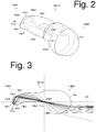
- the first reflecting surface 14b1 can be a surface configured to internally (totally) reflect the first light rays Ray1 having entered through the front incident surface 14a1, and is not formed by metal vapor deposition.
- the first light rays Ray1 passing near the center of the light exiting surface 14c can be increased as compared with the case where the long axis AX 14b1 of the first reflecting surface 14b1 is not inclined with respect to the reference axis AX (see FIG. 10A ). Consequently, the light incident efficiency of the first light rays Ray1 having been internally reflected by the first reflecting surface 14b1 to the light exiting surface 14c can be improved. Furthermore, any Fresnel reflection loss when the first light rays Ray1 exit through the light exiting surface 14c can be suppressed.
- Part of the first light rays Ray1 that have been incident on the front incident surface 14a1 of the incident portion 14a to enter the lens member 14 and internally reflected by the first reflecting surface 14b1 can be shielded by the fourth reflecting surface 14b4.
- Another part (remaining part) of the first light rays Ray1 not shielded by the fourth reflecting surface 14b4 can exit through the lower surface 14c1 of the light exiting surface 14c below the reference axis AX to be projected forward, as illustrated in FIG. 4A .
- the projected light rays can thus form the lower face light distribution pattern P1 14c1 (see FIG. 4D ) including the cut-off line at the upper end edge defined by the front end edge 14b5 of the fourth reflecting surface 14b4. Note that in FIG.
- the reflecting surface namely, the second reflecting surface 14b2
- the hyperbolic shape the position of the other focal point F2 14b2
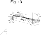
- the shape of the rear incident surface 14a2 the rear splitting angle ⁇ r , the degree of refraction (convergence) of the second light rays Ray2, etc.
- the second reflecting surface 14b2 in its horizontal cross section can be configured such that the low beam light distribution pattern P can have a desired horizontal light intensity distribution.
- the present exemplary embodiment with the above-described configuration, it is possible to form the low beam light distribution pattern P with excellent far-side visibility by means of relatively high light intensity near the cut-off line. This is because the first light rays Ray1 having been internally reflected by the first reflecting surface 14b1 and the second light rays Ray2 having been internally reflected by the third reflecting surface 14b3 can be converged at or near the rear-side focal point F 14c of the light exiting surface 14c with respect to the vertical direction.
Landscapes
- Engineering & Computer Science (AREA)
- General Engineering & Computer Science (AREA)
- Physics & Mathematics (AREA)
- Optics & Photonics (AREA)
- Microelectronics & Electronic Packaging (AREA)
- Non-Portable Lighting Devices Or Systems Thereof (AREA)
Claims (8)
- Lentille (14), à disposer en face d'une source de lumière (12), agencée pour inclure une portion d'extrémité avant (14BB) et une portion d'extrémité arrière (14AA), et pour former un motif de distribution lumineuse (P) prédéterminé comprenant une ligne de coupure au niveau d'un bord supérieur, obtenu en amenant des rayons lumineux émis par la source de lumière (12) et pénétrant dans la lentille (14) à sortir à travers la portion d'extrémité avant (14BB) pour rayonnement, la lentille (14) étant caractérisée en ce qu'elle comprend :une portion incidente (14a) agencée pour permettre aux rayons lumineux provenant de la source de lumière (12) de pénétrer dans la lentille (14) tout en divisant les rayons lumineux entrant en des premiers rayons lumineux (Ray1) qui se déplacent obliquement vers le haut et vers l'avant, et en des deuxièmes rayons lumineux (Ray2) qui se déplacent obliquement vers le haut et vers l'arrière ;une première surface réfléchissante (14b1) agencée pour réfléchir de façon interne les premiers rayons lumineux (Ray1) ;une deuxième surface réfléchissante (14b2) agencée pour réfléchir de façon interne les deuxièmes rayons lumineux (Ray2) ;une troisième surface réfléchissante (14b3) agencée pour réfléchir de façon interne les deuxièmes rayons lumineux (Ray2) qui ont été réfléchis de façon interne par la deuxième surface réfléchissante (14b2) ;une quatrième surface réfléchissante (14b4) agencée pour réfléchir de façon interne au moins une partie des premiers rayons lumineux (Ray1) qui ont été réfléchis de façon interne par la première surface réfléchissante (14b1) et des deuxièmes rayons lumineux (Ray2) qui ont été réfléchis de façon interne par la troisième surface réfléchissante (14b3) ; etune surface de sortie de lumière (14c) disposée au niveau de la portion d'extrémité avant (14BB) et agencée pour être une surface de lentille convexe ayant un point focal du côté arrière (F14c), dans laquellela quatrième surface réfléchissante (14b4) est agencée pour être une surface réfléchissante ayant un bord d'extrémité avant (14b5) et s'étendant vers l'arrière à partir d'une position située au niveau ou à proximité du point focal du côté arrière (F14c) de la surface de sortie de lumière (14c),la portion incidente (14a), la première surface réfléchissante (14b1), la quatrième surface réfléchissante (14b4) et la surface de sortie de lumière (14c) constituent un premier système optique agencé pour former un premier motif de distribution lumineuse partiel (P1) comprenant une ligne de coupure au niveau d'un bord d'extrémité supérieure défini par le bord d'extrémité avant (14b5) de la quatrième surface réfléchissante (14b4), le premier motif de distribution lumineuse partiel (P1) étant formé en faisant rayonner, vers l'avant à travers la surface de sortie de lumière (14c), des rayons lumineux non masqués par la quatrième surface réfléchissante (14b4) et des rayons lumineux réfléchis de façon interne par la quatrième surface réfléchissante (14b4) hors des premiers rayons lumineux (Ray1) qui sont entrés dans la lentille (14) à travers la portion incidente (14a) et qui ont été réfléchis de façon interne par la première surface réfléchissante (14b1),la portion incidente (14a), la deuxième surface réfléchissante (14b2), la troisième surface réfléchissante (14b3), la quatrième surface réfléchissante (14b4) et la surface de sortie de lumière (14c) constituent un deuxième système optique agencé pour former un deuxième motif de distribution lumineuse partiel (P2) comprenant une ligne de coupure au niveau d'un bord d'extrémité supérieure défini par le bord d'extrémité avant (14b5) de la quatrième surface réfléchissante (14b4), le deuxième motif de distribution lumineuse partiel (P2) étant formé en faisant rayonner, vers l'avant à travers la surface de sortie de lumière (14c), des rayons lumineux non masqués par la quatrième surface réfléchissante (14b4) et des rayons lumineux réfléchis de façon interne par la quatrième surface réfléchissante (14b4) hors des deuxièmes rayons lumineux (Ray2) qui sont entrés dans la lentille (14) à travers la portion incidente (14a) et qui sont réfléchis de façon interne par la deuxième surface réfléchissante (14b2) et la troisième surface réfléchissante (14b3) dans l'ordre, etle motif de distribution lumineuse prédéterminé (P) est formé en superposant le premier motif de distribution lumineuse partiel (P1) et le deuxième motif de distribution lumineuse partiel (P2) l'un sur l'autre sous forme d'un motif de distribution lumineuse synthétique.
- Lentille (14) selon la revendication 1,
caractérisée en ce que
la portion incidente (14a) est agencée de manière à inclure une surface incidente avant (14a1) et une surface incidente arrière (14a2), et
la surface incidente avant (14a1) comporte un bord d'extrémité arrière et la surface incidente arrière (14a2) comporte un bord d'extrémité avant de sorte que le bord d'extrémité arrière et le bord d'extrémité avant sont connectés entre eux pour prendre une forme de V ouvert en direction de la source de lumière (12) pour entourer la source de lumière (12) pendant que les surfaces incidentes avant et arrière (14a1, 14a2) connectées sont disposés en face de la source de lumière (12), de sorte que les rayons lumineux émis à partir de la source de lumière (12) sont incidents sur la surface incidente avant (14a1) en tant que les premiers rayons lumineux (Ray1) et sur la surface incidente arrière (14a2) en tant que les deuxièmes rayons lumineux (Ray2). - Lentille (14) selon la revendication 1 ou 2, caractérisée en ce que la troisième surface réfléchissante (14b3) est disposée dans un espace compris entre un premier chemin de lumière dans lequel les premiers rayons lumineux (Ray1) se déplacent et un deuxième chemin de lumière dans lequel les deuxièmes rayons lumineux (Ray2) se déplacent de sorte que les premiers rayons lumineux (Ray1) et les deuxièmes rayons lumineux (Ray2) qui ont pénétré dans la lentille (14) à travers la portion incidente (14a) ne sont pas directement incidents sur la troisième surface réfléchissante (14b3).
- Lentille (14) selon l'une quelconque des revendications 1 à 3, caractérisée en ce que la première surface réfléchissante (14b1) est agencée pour réfléchir de façon interne et faire converger les premiers rayons lumineux (Ray1) au niveau ou à proximité du point focal du côté arrière (F14c) de la surface de sortie de lumière (14c) par rapport à une direction verticale.
- Lentille (14) selon la revendication 4,
caractérisée en ce que la première surface réfléchissante (14b1) est formée par une surface réfléchissante ellipsoïdale agencée pour avoir un premier point focal (F114b1) disposé au niveau ou à proximité du point focal du côté arrière (F14c) de la surface de sortie de lumière (14c) et un deuxième point focal (F214b1) disposé au niveau ou à proximité du point focal virtuel (VF1) qui est une intersection où se coupent les premiers rayons lumineux (Ray1) supposés se déplacer dans la direction inverse. - Lentille (14) selon l'une quelconque des revendications 1 à 5, caractérisée en ce que
la deuxième surface réfléchissante (14b2) est agencée pour réfléchir de façon interne les deuxièmes rayons lumineux (Ray2) pour diriger les deuxièmes rayons lumineux réfléchis de façon interne vers la troisième surface réfléchissante (14b3), et
la troisième surface réfléchissante (14b3) est agencée pour réfléchir de façon interne les deuxièmes rayons lumineux
(Ray2) qui ont été réfléchis de façon interne par la deuxième surface réfléchissante (14b2) pour faire converger les deuxièmes rayons lumineux réfléchis de façon interne (Ray2) vers une position située au niveau ou à proximité du point focal du côté arrière (F14c) de la surface de sortie de lumière (14c) par rapport à la direction verticale. - Lentille (14) selon la revendication 6,
caractérisée en ce que la deuxième surface réfléchissante (14b2) est une surface réfléchissante de forme hyperbolique ayant deux points focaux, un premier point focal (F114b2) disposé au niveau ou à proximité d'un point focal virtuel (VF2) qui est une intersection où les deuxièmes rayons lumineux (Ray2) supposés se déplacer dans une direction inverse se coupent, et un autre point focal (F214b2) disposé en dessous de la source de lumière (12), et
la troisième surface réfléchissante (14b3) est une surface réfléchissante de forme ellipsoïdale ayant un premier point focal (F114b3) disposé au niveau ou à proximité du point focal du côté arrière (F14c) de la surface de sortie de lumière (14c) et un deuxième point focal (F214b3) disposé au niveau ou à proximité de l'autre point focal (F214b2) de la deuxième surface réfléchissante (14b2). - Module d'éclairage pour véhicule (10) caractérisé en ce qu'il comprend une source de lumière (12), et la lentille (14) selon l'une quelconque des revendications 1 à 7.
Applications Claiming Priority (1)
| Application Number | Priority Date | Filing Date | Title |
|---|---|---|---|
| JP2014170208A JP6340751B2 (ja) | 2014-08-25 | 2014-08-25 | レンズ体及び車両用灯具 |
Publications (2)
| Publication Number | Publication Date |
|---|---|
| EP2993392A1 EP2993392A1 (fr) | 2016-03-09 |
| EP2993392B1 true EP2993392B1 (fr) | 2017-03-22 |
Family
ID=54012037
Family Applications (1)
| Application Number | Title | Priority Date | Filing Date |
|---|---|---|---|
| EP15182292.1A Active EP2993392B1 (fr) | 2014-08-25 | 2015-08-25 | Élément de lentille et unité d'éclairage de véhicule |
Country Status (3)
| Country | Link |
|---|---|
| US (1) | US9822947B2 (fr) |
| EP (1) | EP2993392B1 (fr) |
| JP (1) | JP6340751B2 (fr) |
Families Citing this family (27)
| Publication number | Priority date | Publication date | Assignee | Title |
|---|---|---|---|---|
| FR3023600B1 (fr) * | 2014-07-11 | 2021-04-16 | Valeo Vision | Module lumineux d'un vehicule automobile |
| US10634301B2 (en) * | 2015-10-07 | 2020-04-28 | Doctor Optics SE | Light guiding lens for a vehicle headlamp |
| US10174896B2 (en) * | 2015-12-15 | 2019-01-08 | Stanley Electric Co., Ltd. | Lens body and lighting tool for vehicle |
| FR3050010B1 (fr) * | 2016-04-11 | 2018-04-27 | Valeo Vision | Module d'emission de lumiere compact, dispositif et projecteur associes pour vehicule automobile |
| JP6724520B2 (ja) * | 2016-04-21 | 2020-07-15 | 市光工業株式会社 | 車両用灯具 |
| AT518557B1 (de) * | 2016-04-29 | 2018-04-15 | Zkw Group Gmbh | Beleuchtungseinheit für einen Kraftfahrzeugscheinwerfer zum Erzeugen eines Lichtbündels mit Hell-Dunkel-Grenze |
| FR3051541B1 (fr) | 2016-05-18 | 2020-04-17 | Valeo Vision | Projecteur a led a dioptre creant coupure pour vehicules |
| FR3051537B1 (fr) * | 2016-05-18 | 2018-06-29 | Valeo Vision | Dioptre redresseur de coupure |
| JP6688153B2 (ja) * | 2016-05-24 | 2020-04-28 | スタンレー電気株式会社 | レンズ体および車両用灯具 |
| DE102017107781A1 (de) * | 2017-04-11 | 2018-10-11 | Automotive Lighting Reutlingen Gmbh | Primäroptikeinheit für ein Lichtmodul |
| JP6840606B2 (ja) * | 2017-04-14 | 2021-03-10 | スタンレー電気株式会社 | レンズ体および車両用灯具 |
| JP7002235B2 (ja) * | 2017-07-06 | 2022-02-04 | 株式会社小糸製作所 | 拡張反射面を備えたレンズ |
| CN107859968B (zh) * | 2017-11-21 | 2023-10-24 | 华域视觉科技(上海)有限公司 | 车灯照明系统、车灯总成及汽车 |
| KR102470446B1 (ko) * | 2017-12-28 | 2022-11-24 | 에스엘 주식회사 | 차량용 램프 |
| KR102439168B1 (ko) * | 2017-12-29 | 2022-09-01 | 에스엘 주식회사 | 차량용 램프 |
| US10760756B2 (en) * | 2018-07-06 | 2020-09-01 | H.A. Automotive Systems, Inc. | Condenser for low-beam vehicle light module |
| JP7218038B2 (ja) * | 2018-12-04 | 2023-02-06 | 市光工業株式会社 | 車両用灯具 |
| JP7218041B2 (ja) * | 2019-05-21 | 2023-02-06 | 市光工業株式会社 | 車両用導光体及び車両用灯具ユニット |
| US10753562B1 (en) * | 2019-06-09 | 2020-08-25 | Hossein ALISAFAEE | Lightguide headlamp |
| EP4053447A4 (fr) * | 2019-11-01 | 2024-06-19 | Ichikoh Industries, Ltd. | Guide optique de véhicule et phare de véhicule |
| CN113494700B (zh) * | 2020-03-20 | 2025-09-02 | 华域视觉科技(上海)有限公司 | 一种近光初级光学元件、车灯模组、车灯和车辆 |
| JP7424169B2 (ja) * | 2020-03-31 | 2024-01-30 | 市光工業株式会社 | 車両用導光体及び車両用灯具ユニット |
| WO2022044078A1 (fr) * | 2020-08-24 | 2022-03-03 | 三菱電機株式会社 | Module de phare et dispositif de phare |
| JP7134387B1 (ja) | 2021-04-22 | 2022-09-09 | 三菱電機株式会社 | 前照灯モジュール及び前照灯装置 |
| JP7845056B2 (ja) * | 2022-05-31 | 2026-04-14 | 市光工業株式会社 | 車両用導光体及び車両用灯具ユニット |
| KR20240007499A (ko) * | 2022-07-08 | 2024-01-16 | 현대모비스 주식회사 | 차량용 램프 모듈 및 그 램프 모듈을 포함하는 차량용 램프 |
| CN118361683A (zh) * | 2023-01-11 | 2024-07-19 | 华域视觉科技(上海)有限公司 | 一种照明装置和车灯 |
Family Cites Families (6)
| Publication number | Priority date | Publication date | Assignee | Title |
|---|---|---|---|---|
| JPS60164047A (ja) | 1984-02-02 | 1985-08-27 | Tochigi Fuji Ind Co Ltd | 滑り制限差動装置 |
| JP4068387B2 (ja) * | 2002-04-23 | 2008-03-26 | 株式会社小糸製作所 | 光源ユニット |
| JP4047186B2 (ja) | 2003-02-10 | 2008-02-13 | 株式会社小糸製作所 | 車両用前照灯及び光学ユニット |
| FR2884899B1 (fr) * | 2005-04-21 | 2007-06-15 | Valeo Vision Sa | Module d'eclairage donnant un faisceau lumineux avec coupure pour projecteur de vehicule automobile, et projecteur comprenant un tel module |
| US20080260328A1 (en) * | 2007-04-20 | 2008-10-23 | 3M Innovative Properties Company | Led light extraction bar and injection optic for thin lightguide |
| US8733992B2 (en) * | 2012-10-01 | 2014-05-27 | Osram Sylvania, Inc. | LED low profile linear front fog module |
-
2014
- 2014-08-25 JP JP2014170208A patent/JP6340751B2/ja active Active
-
2015
- 2015-08-25 US US14/834,819 patent/US9822947B2/en active Active
- 2015-08-25 EP EP15182292.1A patent/EP2993392B1/fr active Active
Non-Patent Citations (1)
| Title |
|---|
| None * |
Also Published As
| Publication number | Publication date |
|---|---|
| US20160053967A1 (en) | 2016-02-25 |
| JP6340751B2 (ja) | 2018-06-13 |
| JP2016046129A (ja) | 2016-04-04 |
| US9822947B2 (en) | 2017-11-21 |
| EP2993392A1 (fr) | 2016-03-09 |
Similar Documents
| Publication | Publication Date | Title |
|---|---|---|
| EP2993392B1 (fr) | Élément de lentille et unité d'éclairage de véhicule | |
| KR102734822B1 (ko) | 자동차 전조등용 조명 시스템 | |
| JP6448250B2 (ja) | 車両用灯具 | |
| CN217928593U (zh) | 用于车辆的灯 | |
| JP5475395B2 (ja) | 車両用灯具 | |
| JP2017212037A (ja) | 車両用前照灯 | |
| KR102293083B1 (ko) | 자동차 헤드램프용 조명 장치 및 자동차 헤드램프 | |
| US10161592B2 (en) | LED headlamp with refractive interface creating cut-off for vehicles | |
| JP6045834B2 (ja) | 車両用前照灯 | |
| EP2500628A2 (fr) | Phare de véhicule | |
| CN113195969B (zh) | 用于机动车前照灯的照明设备以及机动车前照灯 | |
| JP6688153B2 (ja) | レンズ体および車両用灯具 | |
| JP7503071B2 (ja) | 車両用のマイクロレンズアレイおよびそれを用いた車両用灯具 | |
| CN109073179B (zh) | 车辆用灯具 | |
| WO2014208655A1 (fr) | Luminaire de véhicule | |
| JP5657353B2 (ja) | 車両用灯具 | |
| JP2012164561A (ja) | 灯具ユニット | |
| KR20080090987A (ko) | 차량용 전조등의 등기구 유닛 | |
| CN114623414A (zh) | 用于车辆的灯 | |
| JP6725282B2 (ja) | 車両用灯具 | |
| JP5692520B2 (ja) | 灯具ユニット | |
| JP7577673B2 (ja) | 車両用灯具 | |
| KR101987286B1 (ko) | 차량용 램프 | |
| WO2015079890A1 (fr) | Phare et cache-phare de véhicule | |
| CN116888401A (zh) | 车辆用灯具 |
Legal Events
| Date | Code | Title | Description |
|---|---|---|---|
| PUAI | Public reference made under article 153(3) epc to a published international application that has entered the european phase |
Free format text: ORIGINAL CODE: 0009012 |
|
| AK | Designated contracting states |
Kind code of ref document: A1 Designated state(s): AL AT BE BG CH CY CZ DE DK EE ES FI FR GB GR HR HU IE IS IT LI LT LU LV MC MK MT NL NO PL PT RO RS SE SI SK SM TR |
|
| AX | Request for extension of the european patent |
Extension state: BA ME |
|
| 17P | Request for examination filed |
Effective date: 20160517 |
|
| RBV | Designated contracting states (corrected) |
Designated state(s): AL AT BE BG CH CY CZ DE DK EE ES FI FR GB GR HR HU IE IS IT LI LT LU LV MC MK MT NL NO PL PT RO RS SE SI SK SM TR |
|
| REG | Reference to a national code |
Ref country code: DE Ref legal event code: R079 Ref document number: 602015001917 Country of ref document: DE Free format text: PREVIOUS MAIN CLASS: F21V0007000000 Ipc: F21V0005000000 |
|
| GRAP | Despatch of communication of intention to grant a patent |
Free format text: ORIGINAL CODE: EPIDOSNIGR1 |
|
| RIC1 | Information provided on ipc code assigned before grant |
Ipc: F21V 5/00 20150101AFI20160912BHEP Ipc: F21S 8/12 20060101ALI20160912BHEP Ipc: F21V 7/00 20060101ALI20160912BHEP |
|
| INTG | Intention to grant announced |
Effective date: 20160929 |
|
| GRAS | Grant fee paid |
Free format text: ORIGINAL CODE: EPIDOSNIGR3 |
|
| GRAA | (expected) grant |
Free format text: ORIGINAL CODE: 0009210 |
|
| AK | Designated contracting states |
Kind code of ref document: B1 Designated state(s): AL AT BE BG CH CY CZ DE DK EE ES FI FR GB GR HR HU IE IS IT LI LT LU LV MC MK MT NL NO PL PT RO RS SE SI SK SM TR |
|
| REG | Reference to a national code |
Ref country code: GB Ref legal event code: FG4D |
|
| REG | Reference to a national code |
Ref country code: CH Ref legal event code: EP |
|
| REG | Reference to a national code |
Ref country code: AT Ref legal event code: REF Ref document number: 878154 Country of ref document: AT Kind code of ref document: T Effective date: 20170415 |
|
| REG | Reference to a national code |
Ref country code: IE Ref legal event code: FG4D |
|
| REG | Reference to a national code |
Ref country code: DE Ref legal event code: R096 Ref document number: 602015001917 Country of ref document: DE |
|
| REG | Reference to a national code |
Ref country code: NL Ref legal event code: MP Effective date: 20170322 |
|
| PG25 | Lapsed in a contracting state [announced via postgrant information from national office to epo] |
Ref country code: FI Free format text: LAPSE BECAUSE OF FAILURE TO SUBMIT A TRANSLATION OF THE DESCRIPTION OR TO PAY THE FEE WITHIN THE PRESCRIBED TIME-LIMIT Effective date: 20170322 Ref country code: NO Free format text: LAPSE BECAUSE OF FAILURE TO SUBMIT A TRANSLATION OF THE DESCRIPTION OR TO PAY THE FEE WITHIN THE PRESCRIBED TIME-LIMIT Effective date: 20170622 Ref country code: GR Free format text: LAPSE BECAUSE OF FAILURE TO SUBMIT A TRANSLATION OF THE DESCRIPTION OR TO PAY THE FEE WITHIN THE PRESCRIBED TIME-LIMIT Effective date: 20170623 Ref country code: HR Free format text: LAPSE BECAUSE OF FAILURE TO SUBMIT A TRANSLATION OF THE DESCRIPTION OR TO PAY THE FEE WITHIN THE PRESCRIBED TIME-LIMIT Effective date: 20170322 Ref country code: LT Free format text: LAPSE BECAUSE OF FAILURE TO SUBMIT A TRANSLATION OF THE DESCRIPTION OR TO PAY THE FEE WITHIN THE PRESCRIBED TIME-LIMIT Effective date: 20170322 |
|
| REG | Reference to a national code |
Ref country code: LT Ref legal event code: MG4D |
|
| REG | Reference to a national code |
Ref country code: AT Ref legal event code: MK05 Ref document number: 878154 Country of ref document: AT Kind code of ref document: T Effective date: 20170322 |
|
| REG | Reference to a national code |
Ref country code: FR Ref legal event code: PLFP Year of fee payment: 3 |
|
| PG25 | Lapsed in a contracting state [announced via postgrant information from national office to epo] |
Ref country code: BG Free format text: LAPSE BECAUSE OF FAILURE TO SUBMIT A TRANSLATION OF THE DESCRIPTION OR TO PAY THE FEE WITHIN THE PRESCRIBED TIME-LIMIT Effective date: 20170622 Ref country code: SE Free format text: LAPSE BECAUSE OF FAILURE TO SUBMIT A TRANSLATION OF THE DESCRIPTION OR TO PAY THE FEE WITHIN THE PRESCRIBED TIME-LIMIT Effective date: 20170322 Ref country code: LV Free format text: LAPSE BECAUSE OF FAILURE TO SUBMIT A TRANSLATION OF THE DESCRIPTION OR TO PAY THE FEE WITHIN THE PRESCRIBED TIME-LIMIT Effective date: 20170322 Ref country code: RS Free format text: LAPSE BECAUSE OF FAILURE TO SUBMIT A TRANSLATION OF THE DESCRIPTION OR TO PAY THE FEE WITHIN THE PRESCRIBED TIME-LIMIT Effective date: 20170322 |
|
| PG25 | Lapsed in a contracting state [announced via postgrant information from national office to epo] |
Ref country code: NL Free format text: LAPSE BECAUSE OF FAILURE TO SUBMIT A TRANSLATION OF THE DESCRIPTION OR TO PAY THE FEE WITHIN THE PRESCRIBED TIME-LIMIT Effective date: 20170322 |
|
| PG25 | Lapsed in a contracting state [announced via postgrant information from national office to epo] |
Ref country code: EE Free format text: LAPSE BECAUSE OF FAILURE TO SUBMIT A TRANSLATION OF THE DESCRIPTION OR TO PAY THE FEE WITHIN THE PRESCRIBED TIME-LIMIT Effective date: 20170322 Ref country code: CZ Free format text: LAPSE BECAUSE OF FAILURE TO SUBMIT A TRANSLATION OF THE DESCRIPTION OR TO PAY THE FEE WITHIN THE PRESCRIBED TIME-LIMIT Effective date: 20170322 Ref country code: ES Free format text: LAPSE BECAUSE OF FAILURE TO SUBMIT A TRANSLATION OF THE DESCRIPTION OR TO PAY THE FEE WITHIN THE PRESCRIBED TIME-LIMIT Effective date: 20170322 Ref country code: RO Free format text: LAPSE BECAUSE OF FAILURE TO SUBMIT A TRANSLATION OF THE DESCRIPTION OR TO PAY THE FEE WITHIN THE PRESCRIBED TIME-LIMIT Effective date: 20170322 Ref country code: AT Free format text: LAPSE BECAUSE OF FAILURE TO SUBMIT A TRANSLATION OF THE DESCRIPTION OR TO PAY THE FEE WITHIN THE PRESCRIBED TIME-LIMIT Effective date: 20170322 Ref country code: IT Free format text: LAPSE BECAUSE OF FAILURE TO SUBMIT A TRANSLATION OF THE DESCRIPTION OR TO PAY THE FEE WITHIN THE PRESCRIBED TIME-LIMIT Effective date: 20170322 Ref country code: SK Free format text: LAPSE BECAUSE OF FAILURE TO SUBMIT A TRANSLATION OF THE DESCRIPTION OR TO PAY THE FEE WITHIN THE PRESCRIBED TIME-LIMIT Effective date: 20170322 |
|
| PG25 | Lapsed in a contracting state [announced via postgrant information from national office to epo] |
Ref country code: IS Free format text: LAPSE BECAUSE OF FAILURE TO SUBMIT A TRANSLATION OF THE DESCRIPTION OR TO PAY THE FEE WITHIN THE PRESCRIBED TIME-LIMIT Effective date: 20170722 Ref country code: SM Free format text: LAPSE BECAUSE OF FAILURE TO SUBMIT A TRANSLATION OF THE DESCRIPTION OR TO PAY THE FEE WITHIN THE PRESCRIBED TIME-LIMIT Effective date: 20170322 Ref country code: PL Free format text: LAPSE BECAUSE OF FAILURE TO SUBMIT A TRANSLATION OF THE DESCRIPTION OR TO PAY THE FEE WITHIN THE PRESCRIBED TIME-LIMIT Effective date: 20170322 Ref country code: PT Free format text: LAPSE BECAUSE OF FAILURE TO SUBMIT A TRANSLATION OF THE DESCRIPTION OR TO PAY THE FEE WITHIN THE PRESCRIBED TIME-LIMIT Effective date: 20170724 |
|
| REG | Reference to a national code |
Ref country code: DE Ref legal event code: R097 Ref document number: 602015001917 Country of ref document: DE |
|
| PLBE | No opposition filed within time limit |
Free format text: ORIGINAL CODE: 0009261 |
|
| STAA | Information on the status of an ep patent application or granted ep patent |
Free format text: STATUS: NO OPPOSITION FILED WITHIN TIME LIMIT |
|
| PG25 | Lapsed in a contracting state [announced via postgrant information from national office to epo] |
Ref country code: DK Free format text: LAPSE BECAUSE OF FAILURE TO SUBMIT A TRANSLATION OF THE DESCRIPTION OR TO PAY THE FEE WITHIN THE PRESCRIBED TIME-LIMIT Effective date: 20170322 |
|
| 26N | No opposition filed |
Effective date: 20180102 |
|
| PG25 | Lapsed in a contracting state [announced via postgrant information from national office to epo] |
Ref country code: SI Free format text: LAPSE BECAUSE OF FAILURE TO SUBMIT A TRANSLATION OF THE DESCRIPTION OR TO PAY THE FEE WITHIN THE PRESCRIBED TIME-LIMIT Effective date: 20170322 |
|
| PG25 | Lapsed in a contracting state [announced via postgrant information from national office to epo] |
Ref country code: MC Free format text: LAPSE BECAUSE OF FAILURE TO SUBMIT A TRANSLATION OF THE DESCRIPTION OR TO PAY THE FEE WITHIN THE PRESCRIBED TIME-LIMIT Effective date: 20170322 |
|
| REG | Reference to a national code |
Ref country code: BE Ref legal event code: MM Effective date: 20170831 |
|
| REG | Reference to a national code |
Ref country code: IE Ref legal event code: MM4A |
|
| PG25 | Lapsed in a contracting state [announced via postgrant information from national office to epo] |
Ref country code: LU Free format text: LAPSE BECAUSE OF NON-PAYMENT OF DUE FEES Effective date: 20170825 |
|
| REG | Reference to a national code |
Ref country code: FR Ref legal event code: PLFP Year of fee payment: 4 |
|
| PG25 | Lapsed in a contracting state [announced via postgrant information from national office to epo] |
Ref country code: IE Free format text: LAPSE BECAUSE OF NON-PAYMENT OF DUE FEES Effective date: 20170825 |
|
| PG25 | Lapsed in a contracting state [announced via postgrant information from national office to epo] |
Ref country code: BE Free format text: LAPSE BECAUSE OF NON-PAYMENT OF DUE FEES Effective date: 20170831 |
|
| PG25 | Lapsed in a contracting state [announced via postgrant information from national office to epo] |
Ref country code: MT Free format text: LAPSE BECAUSE OF NON-PAYMENT OF DUE FEES Effective date: 20170825 |
|
| REG | Reference to a national code |
Ref country code: CH Ref legal event code: PL |
|
| PG25 | Lapsed in a contracting state [announced via postgrant information from national office to epo] |
Ref country code: CH Free format text: LAPSE BECAUSE OF NON-PAYMENT OF DUE FEES Effective date: 20180831 Ref country code: LI Free format text: LAPSE BECAUSE OF NON-PAYMENT OF DUE FEES Effective date: 20180831 |
|
| PG25 | Lapsed in a contracting state [announced via postgrant information from national office to epo] |
Ref country code: HU Free format text: LAPSE BECAUSE OF FAILURE TO SUBMIT A TRANSLATION OF THE DESCRIPTION OR TO PAY THE FEE WITHIN THE PRESCRIBED TIME-LIMIT; INVALID AB INITIO Effective date: 20150825 |
|
| PG25 | Lapsed in a contracting state [announced via postgrant information from national office to epo] |
Ref country code: CY Free format text: LAPSE BECAUSE OF FAILURE TO SUBMIT A TRANSLATION OF THE DESCRIPTION OR TO PAY THE FEE WITHIN THE PRESCRIBED TIME-LIMIT Effective date: 20170322 |
|
| PG25 | Lapsed in a contracting state [announced via postgrant information from national office to epo] |
Ref country code: MK Free format text: LAPSE BECAUSE OF FAILURE TO SUBMIT A TRANSLATION OF THE DESCRIPTION OR TO PAY THE FEE WITHIN THE PRESCRIBED TIME-LIMIT Effective date: 20170322 |
|
| PG25 | Lapsed in a contracting state [announced via postgrant information from national office to epo] |
Ref country code: TR Free format text: LAPSE BECAUSE OF FAILURE TO SUBMIT A TRANSLATION OF THE DESCRIPTION OR TO PAY THE FEE WITHIN THE PRESCRIBED TIME-LIMIT Effective date: 20170322 |
|
| PG25 | Lapsed in a contracting state [announced via postgrant information from national office to epo] |
Ref country code: AL Free format text: LAPSE BECAUSE OF FAILURE TO SUBMIT A TRANSLATION OF THE DESCRIPTION OR TO PAY THE FEE WITHIN THE PRESCRIBED TIME-LIMIT Effective date: 20170322 |
|
| PGFP | Annual fee paid to national office [announced via postgrant information from national office to epo] |
Ref country code: GB Payment date: 20240701 Year of fee payment: 10 |
|
| PGFP | Annual fee paid to national office [announced via postgrant information from national office to epo] |
Ref country code: FR Payment date: 20240702 Year of fee payment: 10 |
|
| PGFP | Annual fee paid to national office [announced via postgrant information from national office to epo] |
Ref country code: DE Payment date: 20250702 Year of fee payment: 11 |