EP2993408A1 - Appareil de cuisson et procédé de fonctionnement - Google Patents
Appareil de cuisson et procédé de fonctionnement Download PDFInfo
- Publication number
- EP2993408A1 EP2993408A1 EP15181562.8A EP15181562A EP2993408A1 EP 2993408 A1 EP2993408 A1 EP 2993408A1 EP 15181562 A EP15181562 A EP 15181562A EP 2993408 A1 EP2993408 A1 EP 2993408A1
- Authority
- EP
- European Patent Office
- Prior art keywords
- cooking chamber
- cooking
- temperature sensor
- heater
- safety device
- Prior art date
- Legal status (The legal status is an assumption and is not a legal conclusion. Google has not performed a legal analysis and makes no representation as to the accuracy of the status listed.)
- Granted
Links
Images

Classifications
-
- F—MECHANICAL ENGINEERING; LIGHTING; HEATING; WEAPONS; BLASTING
- F24—HEATING; RANGES; VENTILATING
- F24C—DOMESTIC STOVES OR RANGES ; DETAILS OF DOMESTIC STOVES OR RANGES, OF GENERAL APPLICATION
- F24C15/00—Details
- F24C15/32—Arrangements of ducts for hot gases, e.g. in or around baking ovens
- F24C15/322—Arrangements of ducts for hot gases, e.g. in or around baking ovens with forced circulation
- F24C15/327—Arrangements of ducts for hot gases, e.g. in or around baking ovens with forced circulation with air moisturising
-
- F—MECHANICAL ENGINEERING; LIGHTING; HEATING; WEAPONS; BLASTING
- F24—HEATING; RANGES; VENTILATING
- F24C—DOMESTIC STOVES OR RANGES ; DETAILS OF DOMESTIC STOVES OR RANGES, OF GENERAL APPLICATION
- F24C15/00—Details
- F24C15/003—Details moisturising of air
-
- F—MECHANICAL ENGINEERING; LIGHTING; HEATING; WEAPONS; BLASTING
- F24—HEATING; RANGES; VENTILATING
- F24C—DOMESTIC STOVES OR RANGES ; DETAILS OF DOMESTIC STOVES OR RANGES, OF GENERAL APPLICATION
- F24C7/00—Stoves or ranges heated by electric energy
- F24C7/06—Arrangement or mounting of electric heating elements
-
- F—MECHANICAL ENGINEERING; LIGHTING; HEATING; WEAPONS; BLASTING
- F24—HEATING; RANGES; VENTILATING
- F24C—DOMESTIC STOVES OR RANGES ; DETAILS OF DOMESTIC STOVES OR RANGES, OF GENERAL APPLICATION
- F24C7/00—Stoves or ranges heated by electric energy
- F24C7/08—Arrangement or mounting of control or safety devices
- F24C7/082—Arrangement or mounting of control or safety devices on ranges, e.g. control panels, illumination
- F24C7/085—Arrangement or mounting of control or safety devices on ranges, e.g. control panels, illumination on baking ovens
-
- H—ELECTRICITY
- H05—ELECTRIC TECHNIQUES NOT OTHERWISE PROVIDED FOR
- H05B—ELECTRIC HEATING; ELECTRIC LIGHT SOURCES NOT OTHERWISE PROVIDED FOR; CIRCUIT ARRANGEMENTS FOR ELECTRIC LIGHT SOURCES, IN GENERAL
- H05B6/00—Heating by electric, magnetic or electromagnetic fields
- H05B6/64—Heating using microwaves
- H05B6/647—Aspects related to microwave heating combined with other heating techniques
- H05B6/6473—Aspects related to microwave heating combined with other heating techniques combined with convection heating
- H05B6/6479—Aspects related to microwave heating combined with other heating techniques combined with convection heating using steam
Definitions
- the present invention relates to a cooking appliance comprising at least one housing device and at least one cooking chamber with at least one cooking chamber bottom.
- the cooking chamber is associated with at least one steam generating device for heating food, which is suitable and adapted to supply the cooking chamber with steam.
- On the outside of the cooking chamber floor at least one foil heater is arranged, which is suitable and designed to heat the cooking chamber bottom at least in sections.
- the present invention also relates to a method for operating such a cooking appliance.
- Cooking appliances with a steam generator offer a user the option of preparing food very gently by steam.
- a steam generator in particular steamer
- several methods for steam generation have become known.
- an evaporation surface on the cooking chamber bottom is also advantageous when using an external steam generator.
- steam condenses in both methods on the food and on the food walls and collects on the cooking chamber floor. There, this condensate can then advantageously be evaporated again until a predetermined residual amount of liquid remains on the cooking chamber floor at the end of the cooking process.
- a foil heating element is attached to the cooking space floor from the outside. This is called the cooking chamber floor from the outside and thus provides an evaporation surface on the inside of the cooking chamber floor.
- the cooking appliance according to the invention comprises at least one housing device and at least one cooking chamber with at least one cooking chamber bottom.
- the cooking chamber is associated with at least one steam generating device for heating food, which is suitable and designed to supply the cooking chamber with steam.
- On the outside of the cooking chamber floor at least one foil heater is arranged, which is suitable and designed to heat the cooking chamber bottom at least in sections.
- the cooking chamber bottom has at least one formation on which the film heating element is provided, wherein the film heating element rests against the formation at least in sections and substantially in a form-fitting manner.
- an evaporation surface in the interior of the cooking chamber is provided by the at least partially heating of the cooking chamber bottom from the outside, via which water introduced into the cooking chamber or also condensate that has run down can be vaporized.
- the shaping is designed as a cooking chamber depression, wherein the molding particularly preferably has a three-dimensional shape.
- the film heating element bears directly against the molding and / or is molded onto it. Due to the three-dimensional adaptation of the shape of the foil heater, the heat generated by the foil heater can be transferred particularly effectively to the shape of the cooking chamber floor and thus to the cooking chamber floor.
- the foil heater is designed such that it bears in particular completely positive fit on the molding.
- the cooking appliance according to the invention offers many advantages.
- a considerable advantage is that a cooking chamber floor with a molding or a Garraumsenke is provided by the specially designed foil heater, which can be added to condensed steam in the cooking space to water and at least partially evaporated again.
- the foil heater has a three-dimensional shape, which is adapted to the cooking space sink. So not only the bottom surface of the Garrausenke is heated by the foil heater, but also the side surfaces of the Garraumsenke. As a result, a larger evaporation surface can be made available.
- many other advantages which are explained in more detail with reference to the following explanations.
- the foil heater on a substantially rectangular base. This ensures that the basic structure of the foil heater can be easily and inexpensively manufactured. Starting from the rectangular base, the foil heater can then be adapted to the special design of the shape of the cooking chamber floor.
- the foil heater on at least one slot device.
- a slit device means, in particular, a slot or a cutout or else a recess or a cutout.
- the slot device in the film heating element ensures that it can be better adapted to a three-dimensional shape of the shape of the cooking chamber floor. Depending on the configuration of the shape of the cooking chamber floor, it is also possible to provide a plurality of slot devices or slots in the film heating element.
- the slot device extends from at least one outer contour of the foil heater into the foil heater.
- the slot device In the case of substantially rectangular foil heaters, it is particularly preferred for the slot device to extend into the foil heater, in particular starting from at least one corner towards the center.
- a foil heater are provided with a substantially rectangular base. Slit devices are introduced into the foil heating element in these rectangular foil heating elements, starting from the four corners, so that it can be attached to the base of the formation, whereby the projecting sections of the foil heating element can be adapted by the slitting devices to the further shaping of the shape.
- the formation provides a reservoir for unevaporated residual water. It can be z. B. in internal steam generators, a reservoir for residual evaporation water are made available. If, for example, an external evaporation device is provided, this reservoir can serve for receiving residual condensate, which is no longer to be vaporized.
- the molding has a predetermined maximum level for residual water.
- this predetermined maximum level defines a predetermined receiving volume for residual water, which can not be evaporated or evaporated.
- a receiving volume for residual water of about 100 ml is particularly preferred.
- At least one temperature sensor and / or at least one safety device is assigned to the foil heater.
- a temperature sensor is particularly preferably provided which determines at least one value for determining the temperature at the foil heater.
- a PT1000 is suitable as a temperature sensor.
- Under a safety device according to the invention in particular a safety thermostat to understand, or a circuit breaker that automatically shuts off the foil heater when reaching a predetermined safety temperature.
- the temperature sensor and / or the safety device is provided on an outer portion of the foil heater.
- the temperature sensor and / or the safety device is particularly preferably provided on the outside of the foil heater or on an outer contour of the foil heater.
- the foil heater is then arranged on the molding and / or the temperature sensor and / or the safety device is provided on the foil heater, that the temperature sensor and / or the safety device is substantially assigned to the predetermined level of the molding.
- the temperature of the foil heating element is determined or measured, which is assigned to the region of the maximum filling level of the shape. Characterized in that the temperature sensor and / or the safety device is associated with the maximum level, it can be ensured that the foil heater is issued as soon as the water level has evaporated in the formation so far that the foil heater or the formation in the region of the foil heater is no longer complete or not sufficiently covered with water. Then the foil heater would no longer evaporate water in this area, whereby no decrease in heat takes place, which can lead to overheating of the foil heater.
- At least one temperature sensor and at least one safety device are associated with the foil heater, which are substantially opposite each other.
- the temperature sensor and the safety device in particular face each other in such a way that they are arranged along the width of the cooking chamber. This can be achieved by an appropriate installation of the foil heater.
- opposing temperature sensor and the safety device can, for. B. an inclination or an inclination of the cooking appliance are detected. For example, if the cooking appliance has been set up slightly inclined, it may happen that the water level of the maximum filling quantity of residual water does not lie along the level of the residual water provided in the construction of the cooking appliance. If only then a temperature sensor or a safety device provided on one side, in the worst case, too low a water level in the formation could be detected so late, so that the foil heater is heated too much despite safety measures taken. As a result, a defect of the cooking appliance can be caused in an unfavorable case.
- the safety device is provided substantially in the middle of the foil heater.
- the safety device in the middle of the foil heater is particularly preferably a further or additional safety device to a safety device on the edge of the foil heater.
- a centrally arranged safety device can ensure that the foil heater is turned off if other safety measures fail and the residual water in the molding is substantially completely evaporated by the foil heater.
- the cooking chamber is assigned at least one microwave device for heating food which comprises at least one high-frequency generator which introduces high-frequency radiation at at least one entry point into the cooking chamber.
- a Kombigarêt is provided, can be prepared with the food in steam mode and / or in microwave mode.
- the inventive method is suitable for operating a cooking appliance comprising at least one housing device and at least one cooking chamber with at least one cooking chamber floor.
- the cooking chamber is associated with at least one steam generating device for heating food, which supplies the cooking chamber with steam.
- At least one foil heating element is arranged on the outside of the cooking chamber bottom, which at least partially heats the cooking chamber bottom.
- the cooking chamber floor has at least one formation, on which the film heating element is provided.
- the film heater is at least partially and substantially positively against the formation.
- At least one temperature sensor is assigned to the foil heating element, the foil heating element being switched off when the temperature sensor detects a predetermined temperature change on the foil heating element.
- a characteristic temperature profile indicating that water or Condensate in the cooking chamber was evaporated to a certain residual amount of water.
- a characteristic temperature profile can be calculated or empirically determined and stored in the cooking appliance control.
- a predetermined temperature change is to be understood as meaning, in particular, the exceeding of a specific temperature limit value.
- the temperature sensor preferably determines a predetermined temperature change on the foil heater.
- determining means in particular detecting in this context, wherein the measured or determined values are forwarded to a control device, which evaluates the values and carries out a corresponding action.
- the temperature is preferably determined in particular in the region of the maximum fill level for residual water.
- the inventive method for operating a cooking appliance according to the invention also offers many advantages.
- a considerable advantage is that a particularly effective evaporation surface can be provided on the cooking chamber floor by the three-dimensional design of the film heater, which can also be determined in particular when a predetermined amount of residual water is reached in the formation of Garraumteils.
- the foil heater is turned on again when the temperature sensor detects a second predetermined temperature.
- the second temperature is in particular lower than the first temperature.
- the foil heater can be turned off, for example, when reaching a temperature of 130 ° C. If steam continues to condense in the cooking chamber, the amount of residual water will rise above the predetermined maximum level of residual water, as a result of which the temperature on the film heating element drops again. If a temperature of, for example, less than 128 ° C is reached, the foil heater can be turned on again, so that the water located on the bottom of the oven was again evaporated to a maximum level of residual water.
- other values for the first and the second temperature can also be usefully and preferably used.
- the foil heater is associated with at least one safety device, wherein the foil heater is turned off when the safety device is triggered.
- a safety device is to be understood in particular as a safety thermostat which initiates a safety state, for example at a temperature of 140.degree.
- a safety thermostat is designed, in particular, as a safety protection switch which automatically switches off the foil heating element when a predetermined maximum temperature is reached.
- the security state falls below a certain Limit value withdrawn, whereby the foil heater is activated again or can be activated.
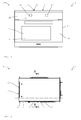
- FIG. 1 an inventive cooking appliance 1 is shown purely schematically in a front view.
- the cooking appliance 1 comprises a housing device 2, in which a cooking chamber 3 is formed.
- the cooking chamber 3 has a feed opening 23 through which food can be introduced into the cooking chamber 3.
- the charging port 23 is in FIG. 1 closed by a cooking chamber door 24.
- the cooking appliance 1 is designed in the embodiment shown here as Kombigarêt 100 and includes a steam generator device 5 and a microwave device 18.
- the steam generator device 5 is suitable and designed to supply the cooking chamber 3 with steam 22.
- the microwave device 18 comprises a microwave generator 19, which introduces high-frequency radiation 20 at an entry point 21 into the cooking chamber 3.
- control panel 25 is provided in the embodiment shown here, which includes two control elements 26 for controlling the cooking appliance 1 here.
- FIG. 2 is purely schematically the cooking chamber 3 of a cooking appliance 1 according to the invention in a purely schematic side view without the outer housing device 2 shown.
- the cooking chamber bottom 4 of the cooking chamber 3 comprises a molding 8, wherein on the outside 6 of the cooking chamber 4, a film heater 7 is provided.
- the foil heater 7 is glued to the outside 6 of the cooking chamber 4 with a suitable adhesive. In other embodiments, the foil heater 7 can also be accommodated differently on the cooking chamber 3.
- the steam generating device 5 is provided in the embodiment shown here as an external steam generator 5, which generates steam outside the cooking chamber 22 and 22 introduces this steam via steam inlets 27 in the cooking chamber 3.
- the introduced into the cooking chamber 3 steam 22 then condenses under certain circumstances on the cooking chamber walls and on the food and collects as condensate 28 on the cooking chamber 4 and in particular in the molding 8 of the cooking chamber 4.
- the formation 8 a reservoir 11 for condensate 28th or for residual water 12 available, which can remain unevaporated in the cooking chamber 3 at the end of a cooking process.
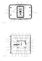
- FIG. 3 is purely schematically a view in the cooking chamber 3 shown, along the sectional plane AA in FIG. 2 is cut. It can be seen that on the rear wall 29 a plurality of steam inlets 27 are provided, through which steam 22 can be introduced into the cooking chamber 3. In addition, a steam outlet 30 is provided, via which excess steam 22 can be removed again from the cooking chamber 3.
- the entry point 21 for high-frequency radiation 20 is provided, via which the high-frequency radiation 20 generated by the high-frequency generator 19 of the microwave device 18 can be introduced into the cooking chamber 3.
- FIG. 4 the cooking chamber 3 of a cooking appliance 1 according to the invention is shown from below.
- the film heating element 7 is provided on the molding 8, which has a substantially rectangular base in the embodiment shown here. So that the film heater 7 can be adapted to the shape or to the contour of the molding 8, four slot devices 9 are provided in the film heater 7, which are formed here as slots 31.
- the slots 31 extend in the embodiment shown here from the outer contour 10 of the foil heater 7 in the direction of the center 17 of the foil heater. 7
- the slot devices 9 are introduced from the corners 32 into the foil heater 7.
- the base of the foil heater 7 may also be designed differently. It is Z. B. also possible that the foil heater 7 has an approximately round shape. Is the formation 8 in the cooking chamber 4 then roundish z. B. in the form of a hemispherical shape 8, for example, a substantially triangular section of the circular foil heater 7 are excluded, so that the foil heater 7 can be adapted to fit the shape 8 in the cooking chamber 4.
- a power supply 42 is provided, via which the foil heater 7 is operated.
- the foil heater 7 comprises a temperature sensor 14 and two safety devices 15.
- the temperature sensor 14 is designed as PT1000 33.
- the safety devices 15 are each provided as a safety thermostat 34.
- the temperature sensor 14 measures the temperature of the film heater 7, wherein the determined values are analyzed by a control device not shown here. If the temperature of the foil heater exceeds 7 z. B. 130 ° C, the film heater 7 can be switched off by the controller.
- An emergency state can be triggered in each case via the two safety devices 15 as soon as a critical predetermined temperature is exceeded. Then the safety thermostat 34 switches off the foil heater 7 automatically, so that overheating is effectively and reliably avoided.
- FIG. 5 is purely schematically a sectional view of the side in the region of the molding 8 in the cooking chamber 4 shown.
- the molding 8 is formed as cooking chamber 35 and provides a reservoir 11 for not to be evaporated residual water 12 available.
- the reservoir 11 has a receiving volume 36, which carries a good 100 ml in the embodiment shown here.
- a maximum predetermined level 13 is provided, up to which condensate 28 can be evaporated by the foil heater 7 and must be evaporated.
- the residual amount 12 of water can also remain after cooking in the cooking chamber 3 or in the molding 8 in the cooking chamber 4.
- the reaching of the maximum fill level 13 is determined in particular via the temperature sensor 14, which is arranged in an outer portion 16 of the foil heater 7.
- the foil heater 7 is then automatically switched off as soon as the temperature sensor 14 detects a first temperature which exceeds 130 ° C. In this case, this first shutdown temperature in other embodiments may preferably be chosen differently.
- the film heater is automatically turned on again.
- the first and / or the second temperature for switching on and off can also be chosen differently.
- other methods may be used expediently in other exemplary embodiments in order to detect whether the maximum fill level 13 has been reached. It can be z. B. the foil heater 7 are switched off at a characteristic temperature profile. Such a characteristic temperature profile can be determined by calculation or empirically and z. B. are deposited in the control device of the cooking appliance 1.
- the foil heater 7 also comprises two safety devices 15.
- a safety device 15 is arranged approximately in the center 17 of the foil heater 7 and a safety device 15 is provided on an outer section 16 of the foil heater 7.
- the two safety devices 15 are designed as safety thermostats 34, which turn off the foil heater 7 when reaching a critical temperature, for example, 140 ° C + 5K tolerance, automatically.
- the critical temperature is selected in the embodiment shown here at 140 ° C. When falling below a predefined non-critical temperature of the critical temperature minus 40K activated by the safety device 15 security state is withdrawn and the foil heater 7 is turned on again.
- Another safety thermostat of the device 15 is designed as a final interrupting switch, which interrupts the power supply to the foil heater 7 when reaching 184 ° C.
- the foil heater 7 is no longer turned on and must be replaced.
- the temperature sensor 14 and the one safety device 15 are both provided on an outer portion 16 of the foil heater 7 in the embodiment shown here and are essentially opposite. In this case, the temperature sensor 14 and the safety device 15 are arranged on the left and right of the formation 8, so that an inclination of the cooking appliance 1 along the width of the cooking appliance can be detected.
- the safety concept of the foil heater 7 with the temperature sensor 14 in conjunction with the safety device 15 is purely schematic in the FIGS. 5 and 6 shown. It is in FIG. 6 to recognize that the cooking appliance 1 has been positioned slightly inclined to the left, so that the maximum level 13 is shifted. As a result, the water surface 38 when reaching the maximum level 13 is no longer exactly between the temperature sensor 14 and the safety device 15. Then the area 37 of the molding 8 is also covered by water 12 when the actual maximum level was 13 below. Thus it could happen that larger areas of the foil heater 7 heat up at the area of the formation 8 when it is no longer covered with water. This can lead to overheating of the foil heater 7, which can lead to technical defects.
- the temperature sensor 14 is still covered by the inclination of the cooking appliance 1 of water 12.
- the safety device 15 is outside the residual water 12, whereby the film heater 7 is automatically turned off when a critical temperature of 140 ° C is exceeded.
- a reliable security concept is provided, which prevents overheating of the foil heater 7 even with an unfavorable mounting of the cooking appliance 1.
- FIG. 7 is a similar situation as in FIG. 6 shown.
- the cooking appliance 1 is tilted to the right, so that the temperature sensor 14 is no longer covered by water 12, while the safety device 15 is still covered by water 12.
- the overheating of the foil heater 7 is achieved by the temperature sensor 14.
- the foil heater 7 is issued as a precaution until the temperature sensor 14 detects a temperature of below 128 ° C.
- the switch-off temperature by the temperature sensor 14 is selected to be lower than the safety temperature of the safety device 15. Should both the temperature sensor 14 and the safety device 15 in the outer portion 16 of the foil heater despite a evaporation end of the residual water 12 below the maximum level 13 not Turn off the foil heater 7, another safety device 15 is provided at the lowest point 39 of the molding 8 to an additional security element available to deliver. Thus, the foil heater 7 and thus the cooking appliance 1 are protected from overheating.
- the cooking appliance 1 provides a cooking appliance 1, in which a molding 8 in the cooking chamber floor 4 is made available for residual water 12, wherein a three-dimensionally shaped film heating body 7 is adapted to the molding 8 in such a way that a particularly effective evaporation surface 40 is provided on the inside side 41 of the cooking compartment 4.
Landscapes
- Engineering & Computer Science (AREA)
- Chemical & Material Sciences (AREA)
- Combustion & Propulsion (AREA)
- Mechanical Engineering (AREA)
- General Engineering & Computer Science (AREA)
- Physics & Mathematics (AREA)
- Electromagnetism (AREA)
- Electric Stoves And Ranges (AREA)
Applications Claiming Priority (1)
| Application Number | Priority Date | Filing Date | Title |
|---|---|---|---|
| DE102014112589.4A DE102014112589B4 (de) | 2014-09-02 | 2014-09-02 | Gargerät und Verfahren zum Betreiben |
Publications (2)
| Publication Number | Publication Date |
|---|---|
| EP2993408A1 true EP2993408A1 (fr) | 2016-03-09 |
| EP2993408B1 EP2993408B1 (fr) | 2019-10-23 |
Family
ID=53938174
Family Applications (1)
| Application Number | Title | Priority Date | Filing Date |
|---|---|---|---|
| EP15181562.8A Active EP2993408B1 (fr) | 2014-09-02 | 2015-08-19 | Appareil de cuisson et procédé de fonctionnement |
Country Status (2)
| Country | Link |
|---|---|
| EP (1) | EP2993408B1 (fr) |
| DE (1) | DE102014112589B4 (fr) |
Families Citing this family (2)
| Publication number | Priority date | Publication date | Assignee | Title |
|---|---|---|---|---|
| DE102016121306B3 (de) | 2016-11-08 | 2017-11-30 | Miele & Cie. Kg | Haushaltgerät und Elektrisches Heizelement zur Verwendung in einem Haushaltgerät |
| DE102019103783A1 (de) * | 2019-02-14 | 2020-08-20 | Rational Aktiengesellschaft | Dampferzeuger für ein Gargerät, Gargerät und Verfahren zum Erzeugen von Dampf |
Citations (5)
| Publication number | Priority date | Publication date | Assignee | Title |
|---|---|---|---|---|
| DE19843842A1 (de) * | 1998-09-24 | 2000-03-30 | Imp Werke Gmbh & Co | Dampfgargerät |
| DE19938612A1 (de) * | 1999-08-14 | 2001-03-01 | Wolf Kunststoffe Gmbh | Behälter, insbesondere zur Aufbewahrung von Lebensmitteln, Speisen oder Getränken |
| EP1658798A1 (fr) * | 2004-11-19 | 2006-05-24 | Whirpool Corporation | Générateur de vapeur pour appareils de cuisson |
| EP1790913A2 (fr) * | 2005-11-24 | 2007-05-30 | Samsung Electronics Co., Ltd. | Plaque chauffante et appareil de cuisson à vapeur comportant celle-ci |
| WO2012076399A1 (fr) * | 2010-12-07 | 2012-06-14 | BSH Bosch und Siemens Hausgeräte GmbH | Support de produit à cuire |
Family Cites Families (5)
| Publication number | Priority date | Publication date | Assignee | Title |
|---|---|---|---|---|
| KR20090085965A (ko) * | 2008-02-05 | 2009-08-10 | 삼성전자주식회사 | 오븐 |
| DE102010029326A1 (de) * | 2010-05-26 | 2011-12-01 | BSH Bosch und Siemens Hausgeräte GmbH | Hausgerät zum Zubereiten von Lebensmitteln |
| EP2462808B1 (fr) * | 2010-12-13 | 2019-11-13 | BSH Hausgeräte GmbH | Appareil de cuisson à vapeur |
| FR2992052B1 (fr) * | 2012-06-14 | 2014-08-22 | Muller & Cie Soc | Appareil de chauffage rayonnant et procede de montage d'un tel appareil |
| EP2789923B1 (fr) * | 2013-04-09 | 2019-06-12 | Electrolux Appliances Aktiebolag | Four électroménager avec évaporateur d'eau intégré |
-
2014
- 2014-09-02 DE DE102014112589.4A patent/DE102014112589B4/de active Active
-
2015
- 2015-08-19 EP EP15181562.8A patent/EP2993408B1/fr active Active
Patent Citations (5)
| Publication number | Priority date | Publication date | Assignee | Title |
|---|---|---|---|---|
| DE19843842A1 (de) * | 1998-09-24 | 2000-03-30 | Imp Werke Gmbh & Co | Dampfgargerät |
| DE19938612A1 (de) * | 1999-08-14 | 2001-03-01 | Wolf Kunststoffe Gmbh | Behälter, insbesondere zur Aufbewahrung von Lebensmitteln, Speisen oder Getränken |
| EP1658798A1 (fr) * | 2004-11-19 | 2006-05-24 | Whirpool Corporation | Générateur de vapeur pour appareils de cuisson |
| EP1790913A2 (fr) * | 2005-11-24 | 2007-05-30 | Samsung Electronics Co., Ltd. | Plaque chauffante et appareil de cuisson à vapeur comportant celle-ci |
| WO2012076399A1 (fr) * | 2010-12-07 | 2012-06-14 | BSH Bosch und Siemens Hausgeräte GmbH | Support de produit à cuire |
Also Published As
| Publication number | Publication date |
|---|---|
| DE102014112589B4 (de) | 2022-05-05 |
| DE102014112589A1 (de) | 2016-03-03 |
| EP2993408B1 (fr) | 2019-10-23 |
Similar Documents
| Publication | Publication Date | Title |
|---|---|---|
| DE102016121306B3 (de) | Haushaltgerät und Elektrisches Heizelement zur Verwendung in einem Haushaltgerät | |
| EP2048444B1 (fr) | Procédé de nettoyage d'un système comprenant un réservoir et un chauffe-eau instantané | |
| EP3470739A1 (fr) | Appareil de cuisson et procédé de mise en uvre d'un procédé de traitement | |
| DE102007029244A1 (de) | Dampferzeuger, Garvorrichtung, Verfahren zum Betrieb beziehungsweise zur Herstellung eines Dampferzeugers sowie Verfahren zum Kühlen einer Heizvorrichtung | |
| EP2466211A1 (fr) | Appareil de cuisson et procédé de fonctionnement d'un appareil de cuisson | |
| DE102014117693A1 (de) | Verfahren zum Erkennen eines Einflusses von Mikrowellen auf einen Messwert eines Temperatursensors, Gargerät sowie Kerntemperaturfühler | |
| WO2017102494A1 (fr) | Procédé permettant de faire fonctionner un appareil de cuisson industriel et appareil de cuisson | |
| EP2993408B1 (fr) | Appareil de cuisson et procédé de fonctionnement | |
| EP3152486A1 (fr) | Évaporateur | |
| EP2543285B2 (fr) | Dispositif de cuisson sous pression et procédé à exécuter | |
| DE102011010224A1 (de) | Hand-Werkzeugmaschine mit einem temperaturabhängigen Sensor | |
| EP2880384B1 (fr) | Appareil frigorifique à dégivrage automatique et procédé de commande d'un tel appareil | |
| EP2468101B1 (fr) | Procédé d'utilisation d'un appareil de cuisson et un appareil de cuisson | |
| EP0892215A2 (fr) | Procédé de commande de la protection de surchauffe pour un appareil de chauffage | |
| EP2339239B1 (fr) | Verrouillage de porte pour appareil électroménager | |
| DE102014112590A1 (de) | Gargerät und Verfahren | |
| EP3647664B1 (fr) | Procédé de fonctionnement automatique d'un appareil de cuisson à la vapeur et appareil de cuisson à la vapeur correspondant | |
| EP2345350B1 (fr) | Appareil de cuisson | |
| DE102016108535A1 (de) | Verfahren zum Steuern einer Pumpe in einem Gargerät sowie Gargerät | |
| EP3383139A1 (fr) | Dispositif d'appareil de cuisson | |
| DE102014112592A1 (de) | Gargerät | |
| DE202012005348U1 (de) | Elektrischer Kaffeevollautomat | |
| EP2428735B1 (fr) | Appareil de cuisson doté d'un générateur de vapeur et procédé de réglage d'un générateur de vapeur pour un appareil de cuisson | |
| DE102012219525A1 (de) | Vorrichtung und Verfahren zum Kompaktieren von Kunststoffflaschen | |
| DE102014104796A1 (de) | Garzubehör für ein Gargerät zum Erwärmen eines Garguts |
Legal Events
| Date | Code | Title | Description |
|---|---|---|---|
| PUAI | Public reference made under article 153(3) epc to a published international application that has entered the european phase |
Free format text: ORIGINAL CODE: 0009012 |
|
| AK | Designated contracting states |
Kind code of ref document: A1 Designated state(s): AL AT BE BG CH CY CZ DE DK EE ES FI FR GB GR HR HU IE IS IT LI LT LU LV MC MK MT NL NO PL PT RO RS SE SI SK SM TR |
|
| 17P | Request for examination filed |
Effective date: 20160909 |
|
| RBV | Designated contracting states (corrected) |
Designated state(s): AL AT BE BG CH CY CZ DE DK EE ES FI FR GB GR HR HU IE IS IT LI LT LU LV MC MK MT NL NO PL PT RO RS SE SI SK SM TR |
|
| STAA | Information on the status of an ep patent application or granted ep patent |
Free format text: STATUS: EXAMINATION IS IN PROGRESS |
|
| 17Q | First examination report despatched |
Effective date: 20170317 |
|
| GRAP | Despatch of communication of intention to grant a patent |
Free format text: ORIGINAL CODE: EPIDOSNIGR1 |
|
| STAA | Information on the status of an ep patent application or granted ep patent |
Free format text: STATUS: GRANT OF PATENT IS INTENDED |
|
| RIC1 | Information provided on ipc code assigned before grant |
Ipc: F24C 15/00 20060101ALI20190516BHEP Ipc: H05B 6/64 20060101ALI20190516BHEP Ipc: F24C 7/08 20060101ALI20190516BHEP Ipc: F24C 7/06 20060101AFI20190516BHEP Ipc: F24C 15/32 20060101ALI20190516BHEP |
|
| INTG | Intention to grant announced |
Effective date: 20190613 |
|
| GRAS | Grant fee paid |
Free format text: ORIGINAL CODE: EPIDOSNIGR3 |
|
| GRAA | (expected) grant |
Free format text: ORIGINAL CODE: 0009210 |
|
| STAA | Information on the status of an ep patent application or granted ep patent |
Free format text: STATUS: THE PATENT HAS BEEN GRANTED |
|
| REG | Reference to a national code |
Ref country code: DE Ref legal event code: R084 Ref document number: 502015010713 Country of ref document: DE |
|
| AK | Designated contracting states |
Kind code of ref document: B1 Designated state(s): AL AT BE BG CH CY CZ DE DK EE ES FI FR GB GR HR HU IE IS IT LI LT LU LV MC MK MT NL NO PL PT RO RS SE SI SK SM TR |
|
| REG | Reference to a national code |
Ref country code: GB Ref legal event code: FG4D Free format text: NOT ENGLISH |
|
| REG | Reference to a national code |
Ref country code: CH Ref legal event code: EP |
|
| REG | Reference to a national code |
Ref country code: IE Ref legal event code: FG4D Free format text: LANGUAGE OF EP DOCUMENT: GERMAN |
|
| REG | Reference to a national code |
Ref country code: DE Ref legal event code: R096 Ref document number: 502015010713 Country of ref document: DE |
|
| REG | Reference to a national code |
Ref country code: AT Ref legal event code: REF Ref document number: 1194068 Country of ref document: AT Kind code of ref document: T Effective date: 20191115 Ref country code: CH Ref legal event code: NV Representative=s name: COSMOVICI INTELLECTUAL PROPERTY SARL, CH |
|
| REG | Reference to a national code |
Ref country code: NL Ref legal event code: FP |
|
| REG | Reference to a national code |
Ref country code: LT Ref legal event code: MG4D |
|
| PG25 | Lapsed in a contracting state [announced via postgrant information from national office to epo] |
Ref country code: LV Free format text: LAPSE BECAUSE OF FAILURE TO SUBMIT A TRANSLATION OF THE DESCRIPTION OR TO PAY THE FEE WITHIN THE PRESCRIBED TIME-LIMIT Effective date: 20191023 Ref country code: SE Free format text: LAPSE BECAUSE OF FAILURE TO SUBMIT A TRANSLATION OF THE DESCRIPTION OR TO PAY THE FEE WITHIN THE PRESCRIBED TIME-LIMIT Effective date: 20191023 Ref country code: NO Free format text: LAPSE BECAUSE OF FAILURE TO SUBMIT A TRANSLATION OF THE DESCRIPTION OR TO PAY THE FEE WITHIN THE PRESCRIBED TIME-LIMIT Effective date: 20200123 Ref country code: PL Free format text: LAPSE BECAUSE OF FAILURE TO SUBMIT A TRANSLATION OF THE DESCRIPTION OR TO PAY THE FEE WITHIN THE PRESCRIBED TIME-LIMIT Effective date: 20191023 Ref country code: ES Free format text: LAPSE BECAUSE OF FAILURE TO SUBMIT A TRANSLATION OF THE DESCRIPTION OR TO PAY THE FEE WITHIN THE PRESCRIBED TIME-LIMIT Effective date: 20191023 Ref country code: LT Free format text: LAPSE BECAUSE OF FAILURE TO SUBMIT A TRANSLATION OF THE DESCRIPTION OR TO PAY THE FEE WITHIN THE PRESCRIBED TIME-LIMIT Effective date: 20191023 Ref country code: GR Free format text: LAPSE BECAUSE OF FAILURE TO SUBMIT A TRANSLATION OF THE DESCRIPTION OR TO PAY THE FEE WITHIN THE PRESCRIBED TIME-LIMIT Effective date: 20200124 Ref country code: BG Free format text: LAPSE BECAUSE OF FAILURE TO SUBMIT A TRANSLATION OF THE DESCRIPTION OR TO PAY THE FEE WITHIN THE PRESCRIBED TIME-LIMIT Effective date: 20200123 Ref country code: FI Free format text: LAPSE BECAUSE OF FAILURE TO SUBMIT A TRANSLATION OF THE DESCRIPTION OR TO PAY THE FEE WITHIN THE PRESCRIBED TIME-LIMIT Effective date: 20191023 Ref country code: PT Free format text: LAPSE BECAUSE OF FAILURE TO SUBMIT A TRANSLATION OF THE DESCRIPTION OR TO PAY THE FEE WITHIN THE PRESCRIBED TIME-LIMIT Effective date: 20200224 |
|
| PG25 | Lapsed in a contracting state [announced via postgrant information from national office to epo] |
Ref country code: HR Free format text: LAPSE BECAUSE OF FAILURE TO SUBMIT A TRANSLATION OF THE DESCRIPTION OR TO PAY THE FEE WITHIN THE PRESCRIBED TIME-LIMIT Effective date: 20191023 Ref country code: IS Free format text: LAPSE BECAUSE OF FAILURE TO SUBMIT A TRANSLATION OF THE DESCRIPTION OR TO PAY THE FEE WITHIN THE PRESCRIBED TIME-LIMIT Effective date: 20200224 Ref country code: RS Free format text: LAPSE BECAUSE OF FAILURE TO SUBMIT A TRANSLATION OF THE DESCRIPTION OR TO PAY THE FEE WITHIN THE PRESCRIBED TIME-LIMIT Effective date: 20191023 |
|
| PG25 | Lapsed in a contracting state [announced via postgrant information from national office to epo] |
Ref country code: AL Free format text: LAPSE BECAUSE OF FAILURE TO SUBMIT A TRANSLATION OF THE DESCRIPTION OR TO PAY THE FEE WITHIN THE PRESCRIBED TIME-LIMIT Effective date: 20191023 |
|
| REG | Reference to a national code |
Ref country code: DE Ref legal event code: R097 Ref document number: 502015010713 Country of ref document: DE |
|
| PG2D | Information on lapse in contracting state deleted |
Ref country code: IS |
|
| PG25 | Lapsed in a contracting state [announced via postgrant information from national office to epo] |
Ref country code: IS Free format text: LAPSE BECAUSE OF FAILURE TO SUBMIT A TRANSLATION OF THE DESCRIPTION OR TO PAY THE FEE WITHIN THE PRESCRIBED TIME-LIMIT Effective date: 20200223 Ref country code: EE Free format text: LAPSE BECAUSE OF FAILURE TO SUBMIT A TRANSLATION OF THE DESCRIPTION OR TO PAY THE FEE WITHIN THE PRESCRIBED TIME-LIMIT Effective date: 20191023 Ref country code: CZ Free format text: LAPSE BECAUSE OF FAILURE TO SUBMIT A TRANSLATION OF THE DESCRIPTION OR TO PAY THE FEE WITHIN THE PRESCRIBED TIME-LIMIT Effective date: 20191023 Ref country code: RO Free format text: LAPSE BECAUSE OF FAILURE TO SUBMIT A TRANSLATION OF THE DESCRIPTION OR TO PAY THE FEE WITHIN THE PRESCRIBED TIME-LIMIT Effective date: 20191023 Ref country code: DK Free format text: LAPSE BECAUSE OF FAILURE TO SUBMIT A TRANSLATION OF THE DESCRIPTION OR TO PAY THE FEE WITHIN THE PRESCRIBED TIME-LIMIT Effective date: 20191023 |
|
| PLBE | No opposition filed within time limit |
Free format text: ORIGINAL CODE: 0009261 |
|
| STAA | Information on the status of an ep patent application or granted ep patent |
Free format text: STATUS: NO OPPOSITION FILED WITHIN TIME LIMIT |
|
| PG25 | Lapsed in a contracting state [announced via postgrant information from national office to epo] |
Ref country code: SM Free format text: LAPSE BECAUSE OF FAILURE TO SUBMIT A TRANSLATION OF THE DESCRIPTION OR TO PAY THE FEE WITHIN THE PRESCRIBED TIME-LIMIT Effective date: 20191023 Ref country code: SK Free format text: LAPSE BECAUSE OF FAILURE TO SUBMIT A TRANSLATION OF THE DESCRIPTION OR TO PAY THE FEE WITHIN THE PRESCRIBED TIME-LIMIT Effective date: 20191023 Ref country code: IT Free format text: LAPSE BECAUSE OF FAILURE TO SUBMIT A TRANSLATION OF THE DESCRIPTION OR TO PAY THE FEE WITHIN THE PRESCRIBED TIME-LIMIT Effective date: 20191023 |
|
| 26N | No opposition filed |
Effective date: 20200724 |
|
| PG25 | Lapsed in a contracting state [announced via postgrant information from national office to epo] |
Ref country code: SI Free format text: LAPSE BECAUSE OF FAILURE TO SUBMIT A TRANSLATION OF THE DESCRIPTION OR TO PAY THE FEE WITHIN THE PRESCRIBED TIME-LIMIT Effective date: 20191023 |
|
| PG25 | Lapsed in a contracting state [announced via postgrant information from national office to epo] |
Ref country code: MC Free format text: LAPSE BECAUSE OF FAILURE TO SUBMIT A TRANSLATION OF THE DESCRIPTION OR TO PAY THE FEE WITHIN THE PRESCRIBED TIME-LIMIT Effective date: 20191023 |
|
| GBPC | Gb: european patent ceased through non-payment of renewal fee |
Effective date: 20200819 |
|
| PG25 | Lapsed in a contracting state [announced via postgrant information from national office to epo] |
Ref country code: LU Free format text: LAPSE BECAUSE OF NON-PAYMENT OF DUE FEES Effective date: 20200819 |
|
| PG25 | Lapsed in a contracting state [announced via postgrant information from national office to epo] |
Ref country code: FR Free format text: LAPSE BECAUSE OF NON-PAYMENT OF DUE FEES Effective date: 20200831 |
|
| PG25 | Lapsed in a contracting state [announced via postgrant information from national office to epo] |
Ref country code: IE Free format text: LAPSE BECAUSE OF NON-PAYMENT OF DUE FEES Effective date: 20200819 Ref country code: GB Free format text: LAPSE BECAUSE OF NON-PAYMENT OF DUE FEES Effective date: 20200819 |
|
| PG25 | Lapsed in a contracting state [announced via postgrant information from national office to epo] |
Ref country code: TR Free format text: LAPSE BECAUSE OF FAILURE TO SUBMIT A TRANSLATION OF THE DESCRIPTION OR TO PAY THE FEE WITHIN THE PRESCRIBED TIME-LIMIT Effective date: 20191023 Ref country code: MT Free format text: LAPSE BECAUSE OF FAILURE TO SUBMIT A TRANSLATION OF THE DESCRIPTION OR TO PAY THE FEE WITHIN THE PRESCRIBED TIME-LIMIT Effective date: 20191023 Ref country code: CY Free format text: LAPSE BECAUSE OF FAILURE TO SUBMIT A TRANSLATION OF THE DESCRIPTION OR TO PAY THE FEE WITHIN THE PRESCRIBED TIME-LIMIT Effective date: 20191023 |
|
| PG25 | Lapsed in a contracting state [announced via postgrant information from national office to epo] |
Ref country code: MK Free format text: LAPSE BECAUSE OF FAILURE TO SUBMIT A TRANSLATION OF THE DESCRIPTION OR TO PAY THE FEE WITHIN THE PRESCRIBED TIME-LIMIT Effective date: 20191023 |
|
| P01 | Opt-out of the competence of the unified patent court (upc) registered |
Effective date: 20230528 |
|
| PGFP | Annual fee paid to national office [announced via postgrant information from national office to epo] |
Ref country code: NL Payment date: 20250825 Year of fee payment: 11 |
|
| PGFP | Annual fee paid to national office [announced via postgrant information from national office to epo] |
Ref country code: DE Payment date: 20250831 Year of fee payment: 11 |
|
| PGFP | Annual fee paid to national office [announced via postgrant information from national office to epo] |
Ref country code: BE Payment date: 20250825 Year of fee payment: 11 |
|
| PGFP | Annual fee paid to national office [announced via postgrant information from national office to epo] |
Ref country code: AT Payment date: 20250819 Year of fee payment: 11 |
|
| PGFP | Annual fee paid to national office [announced via postgrant information from national office to epo] |
Ref country code: CH Payment date: 20250901 Year of fee payment: 11 |