EP2993459B1 - Optischer impulstester - Google Patents
Optischer impulstester Download PDFInfo
- Publication number
- EP2993459B1 EP2993459B1 EP15179554.9A EP15179554A EP2993459B1 EP 2993459 B1 EP2993459 B1 EP 2993459B1 EP 15179554 A EP15179554 A EP 15179554A EP 2993459 B1 EP2993459 B1 EP 2993459B1
- Authority
- EP
- European Patent Office
- Prior art keywords
- function
- otdr
- optical
- measurement
- auxiliary
- Prior art date
- Legal status (The legal status is an assumption and is not a legal conclusion. Google has not performed a legal analysis and makes no representation as to the accuracy of the status listed.)
- Active
Links
Images


Classifications
-
- G—PHYSICS
- G01—MEASURING; TESTING
- G01M—TESTING STATIC OR DYNAMIC BALANCE OF MACHINES OR STRUCTURES; TESTING OF STRUCTURES OR APPARATUS, NOT OTHERWISE PROVIDED FOR
- G01M11/00—Testing of optical apparatus; Testing structures by optical methods not otherwise provided for
- G01M11/30—Testing of optical devices, constituted by fibre optics or optical waveguides
- G01M11/31—Testing of optical devices, constituted by fibre optics or optical waveguides with a light emitter and a light receiver being disposed at the same side of a fibre or waveguide end-face, e.g. reflectometers
- G01M11/3109—Reflectometers detecting the back-scattered light in the time-domain, e.g. OTDR
- G01M11/3145—Details of the optoelectronics or data analysis
-
- G—PHYSICS
- G01—MEASURING; TESTING
- G01M—TESTING STATIC OR DYNAMIC BALANCE OF MACHINES OR STRUCTURES; TESTING OF STRUCTURES OR APPARATUS, NOT OTHERWISE PROVIDED FOR
- G01M11/00—Testing of optical apparatus; Testing structures by optical methods not otherwise provided for
- G01M11/30—Testing of optical devices, constituted by fibre optics or optical waveguides
- G01M11/31—Testing of optical devices, constituted by fibre optics or optical waveguides with a light emitter and a light receiver being disposed at the same side of a fibre or waveguide end-face, e.g. reflectometers
- G01M11/3109—Reflectometers detecting the back-scattered light in the time-domain, e.g. OTDR
- G01M11/3127—Reflectometers detecting the back-scattered light in the time-domain, e.g. OTDR using multiple or wavelength variable input source
-
- G—PHYSICS
- G01—MEASURING; TESTING
- G01M—TESTING STATIC OR DYNAMIC BALANCE OF MACHINES OR STRUCTURES; TESTING OF STRUCTURES OR APPARATUS, NOT OTHERWISE PROVIDED FOR
- G01M11/00—Testing of optical apparatus; Testing structures by optical methods not otherwise provided for
- G01M11/30—Testing of optical devices, constituted by fibre optics or optical waveguides
- G01M11/31—Testing of optical devices, constituted by fibre optics or optical waveguides with a light emitter and a light receiver being disposed at the same side of a fibre or waveguide end-face, e.g. reflectometers
- G01M11/3109—Reflectometers detecting the back-scattered light in the time-domain, e.g. OTDR
- G01M11/3136—Reflectometers detecting the back-scattered light in the time-domain, e.g. OTDR for testing of multiple fibers
-
- H—ELECTRICITY
- H04—ELECTRIC COMMUNICATION TECHNIQUE
- H04B—TRANSMISSION
- H04B10/00—Transmission systems employing electromagnetic waves other than radio-waves, e.g. infrared, visible or ultraviolet light, or employing corpuscular radiation, e.g. quantum communication
- H04B10/07—Arrangements for monitoring or testing transmission systems; Arrangements for fault measurement of transmission systems
- H04B10/071—Arrangements for monitoring or testing transmission systems; Arrangements for fault measurement of transmission systems using a reflected signal, e.g. using optical time domain reflectometers [OTDR]
Definitions
- the present disclosure relates to an optical pulse tester.
- optical fibers are used as media for transmitting the optical signals.
- the length of the optical fiber and loss and reflection at a connection portion of the optical fiber are evaluated, for example.
- Optical pulse testers (OTDRs: Optical Time Domain Reflectometers) are used as measuring instruments.
- the optical pulse tester emits, as measurement light, an optical pulse to a measurement target optical fiber connected to an optical connector.
- the optical pulse tester measures, in a time domain, the power of return light (backscattered light and/or Fresnel reflection light) returning to an input end.
- the optical pulse tester displays measurement results, and analyzes the measurement results, for example.
- the return light such as backscattered light returns to an input side in a delay time proportional to the distance from a reflection point.
- the return light forms a characteristic waveform at, e.g., a welded point, a connector connection point, a branching point, a bending point, and a cutting point of the optical fiber.
- an event at the optical fiber is detected from the waveform of the power of the return light, the event including, e.g., the welded point, the connector connection point, the branching point, the bending point, and the cutting point. Then, the distance to the event (the position of the event) is measured.
- an optical pulse tester has various auxiliary functions in addition to the original OTDR function of analyzing the time distribution of the power of the return light.
- auxiliary functions include a stabilized light source function, a visible light source function, an optical power meter function, and a fiber end face inspection function.
- Fig. 6 is a view illustrating a menu system of a typical optical pulse tester having a plurality of auxiliary functions. As illustrated in Fig. 6 , in the typical optical pulse tester, menu items for calling the function of "OTDR measurement,” a “stabilized light source,” a “visible light source,” an “optical power meter,” or “end face inspection” are displayed as a top screen.
- an OTDR measurement screen is displayed.
- a screen for light emission of a light source is displayed.
- the "optical power meter” is selected, a screen indicating an input optical power is displayed. A user can select, from the top screen, a menu item of a function corresponding to a measurement purpose to cause the optical pulse tester to execute a desired function.
- Examples of documents on this field include JP-A-09-145538 .
- JP 2009 058279 A discloses an optical path abnormality diagnosing apparatus and an operating screen display method, wherein the optical path abnormality diagnosing apparatus sequentially conducts an optical communication signal strength test, an OTDR test and a visible light test and is equipped with a display part which displays details regarding each test.
- EP 1 069 409 A2 discloses a measurement data display apparatus having an input section, a display section and a control section in order to display a measurement data of a measured object on a screen.
- the input section is provided on the front side of the measurement data display apparatus, and includes at least a first key, a second key and a plurality of function keys.
- an optical pulse tester as set out in independent claim 1.
- Advantageous developments are defined in the dependent claims.
- multicore optical fiber cables are used at, e.g., data centers.
- a typical series of processing is often performed sequentially for a plurality of optical fibers.
- the present disclosure is, as one purpose, intended to enhance the operational efficiency when processing is performed for a plurality of optical fibers by an optical pulse tester having auxiliary functions.
- An optical pulse tester includes: an OTDR measurer configured to execute an OTDR function of measuring a time distribution of a power of return light of an optical pulse input to an optical fiber; a display configured to display an OTDR measurement screen indicating information on execution of the OTDR function; and a controller configured to control the OTDR measurer and the display.
- the controller displays, on the OTDR measurement screen, upon selection of an icon on the OTDR measurement screen, a menu including a plurality of auxiliary functions for allowing an operating person to call each auxiliary function of the plurality of auxiliary functions for measurement of the optical fiber without returning to a top screen during execution of the OTDR function, and displays, on the OTDR measurement screen, upon call of an auxiliary function by the operating person, a sub-screen indicating information on execution of the auxiliary function called by the operating person.
- the present tester may further include: a first port for the OTDR function; a second port for the auxiliary function for the measurement of the optical fiber; and an auxiliary function executer configured to execute the auxiliary function for the measurement of the optical fiber.
- the controller may control the auxiliary function executer.
- the controller may control the auxiliary function executer according to an execution instruction of the operating person input to the sub-screen, and executes the called auxiliary function.
- the controller may execute the OTDR function and the auxiliary function in parallel.
- the plurality of auxiliary functions includes a stabilized light source function of continuously emitting measurement light, a visible light source function of emitting visible light, an optical power meter function of measuring a power of light emitted from the optical fiber, and a fiber end face inspection function.
- the controller pops up the menu according to a predetermined operation of the operating person.
- Fig. 1 is a block diagram illustrating the configuration of an optical pulse tester 100 of the present embodiment.
- the optical pulse tester 100 has the OTDR function of analyzing the time distribution of the power of return light.
- the optical pulse tester 100 has, as auxiliary functions for measurement of an optical fiber, a stabilized light source function, a visible light source function, an optical power meter function, and a fiber end face inspection function.
- the stabilized light source function described herein is the function of continuously emitting measurement light from an optical connector.
- the optical pulse tester 100 with this function can be used as, e.g., a light source for loss measurement.
- the visible light source function is the function of continuously emitting visible light from an optical connector.
- the optical pulse tester 100 with this function can be used for, e.g., checking of the core of a multicore fiber and visual checking of a failure portion.
- the optical power meter function is the function of measuring the power of light emitted from an optical fiber connected to an optical connector.
- the optical pulse tester 100 with this function can be used for, e.g., checking of the optical power in connection testing or failure occurrence.
- the fiber end face inspection function is, e.g., the function of enlarging an end face image of an optical fiber.
- the optical pulse tester 100 with this function can be used for checking of connectivity of a connector of an optical fiber.
- an end face inspection device connected to an USB port is used for end face inspection.
- the optical pulse tester 100 sequentially performs, for a plurality of optical fibers 200, fiber end face inspection, optical power measurement, and OTDR measurement will be described as an example.
- the optical pulse tester 100 includes a controller 101, a light source/measurer 102, an optical power meter 103, an OTDR measurer 104, an end face analyzer 105, a light emission/receiving port 110, a visible light emission port 111, a light receiving port 120, an operation receiver 130, a display 140, an USB port 150.
- the light source/measurer 102, the optical power meter 103, and the end face analyzer 105 are examples of an auxiliary function executer.
- the light emission/receiving port 110 is one example of a first port.
- the visible light emission port 111, the light receiving port 120, and the USB port 150 are examples of a second port.
- the optical fibers 200 are connected to the first and second ports.
- the controller 101 controls, according to a user operation received via the operation receiver 130, measurement processing and various operations in the optical pulse tester 100.
- the light source/measurer 102 performs, in execution of the OTDR function, light emission processing of light emitted to the optical fiber 200 connected to the light emission/receiving port 110 and light receiving processing of return light. Moreover, the light source/measurer 102 performs, in execution of the stabilized light source function, light emission processing of continuous light emitted to the optical fiber 200 connected to the light emission/receiving port 110. Further, the light source/measurer 102 performs, in execution of the visible light source function, light emission processing of visible light emitted to the optical fiber 200 connected to the visible light emission port 111.
- the controller 101 controls the light source/measurer 102 and the OTDR measurer 104 according to an instruction from the operating person, and then, executes the OTDR function (OTDR measurement).
- the controller 101 controls the light source/measurer 102 according to an instruction from the operating person, and then, executes the stabilized light source function or the visible light source function.
- the controller 101 controls the optical power meter 103 according to an instruction from the operating person, and then, executes the optical power meter function.
- the controller 101 controls the end face analyzer 105 according to an instruction from the operating person, and then, executes the fiber end face inspection function.
- the optical power meter 103 measures, in execution of the optical power meter function, the power of light emitted from the optical fiber 200 connected to the light receiving port 120. Note that the light receiving port 120 and the visible light emission port 111 may be the same port.
- the OTDR measurer 104 performs, in execution of the OTDR function, the OTDR measurement based on the results of the light emission/receiving processing of the light source/measurer 102.
- the end face analyzer 105 is, in execution of the fiber end face inspection function, connected to an end face inspection device 180 via the USB port 150.
- the end face analyzer 105 checks the connector connectivity of the optical fiber 200 connected to the end face inspection device 180.
- the optical power meter 103, the OTDR measurer 104, and the end face analyzer 105 are functionally independent from each other.
- the OTDR measurer 104 further performs the OTDR measurement for the optical fiber 200 connected to the light emission/receiving port 110.
- the optical power meter 103 performs the optical power measurement for the optical fiber 200 connected to the light receiving port 120.
- the end face analyzer 105 performs the end face inspection for the optical fiber 200 connected to the end face inspection device 180.
- the OTDR measurement, the optical power measurement, and the end face inspection can be simultaneously performed. Further, visible light can be emitted in parallel to the OTDR measurement.
- the operation receiver 130 receives various operations from the user.
- the display 140 displays, e.g., a menu and measurement results based on the display control of the controller 101.
- Fig. 2 illustrates the exterior appearance of the operation receiver 130 and the display 140.
- the operation receiver 130 includes a power switch 131, a rotary knob 132, a scale key 133, a direction/enter key 134, a setup (SETUP) key 135, a real time measurement (REAL TIME) key 136, an averaging (AVE) key 137, and a function key 138.
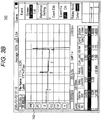
- the controller 101 displays, in execution of the OTDR function, an OTDR measurement screen as a main screen (a main function) on the display 140 as illustrated in Fig. 3A .
- This OTDR measurement screen shows information (e.g., the results of the OTDR measurement) on execution of the OTDR function.
- the controller 101 creates an arrow icon 142 on the OTDR measurement screen.
- the arrow icon 142 is the icon for displaying a launcher menu for selecting (calling) the auxiliary function.
- the controller 101 pops up, as illustrated in Fig. 3B , a launcher menu 143 on the OTDR measurement screen.
- the launcher menu 143 includes an "OPM” icon, an "LS” icon, a “VLS” icon, and an "FIP” icon.
- the "OPM” icon is the icon for calling the optical power meter function.
- the "LS” icon is the icon for calling the stabilized light source function.
- the “VLS” icon is the icon for calling the visible light source function.
- the "FIP” icon is the icon for calling the fiber end face inspection function.
- each auxiliary function can be called without returning to the top screen during execution of the OTDR measurement.
- it is not necessary to frequently switch a screen. This can prevent or reduce complication of the operation.
- auxiliary function When a certain auxiliary function is called from the launcher menu 143, a sub-screen for such an auxiliary function is displayed on the OTDR measurement screen (displayed to overlap the OTDR measurement screen). The operating person uses the called sub-screen to execute the auxiliary function. Information on execution of the auxiliary function called by the operating person is displayed on the sub-screen. The controller 101 continues the OTDR measurement even during displaying of the sub-screen.
- an optical power measurement sub-screen 144 indicating an optical power measurement value is displayed on an OTDR measurement screen 141 as illustrated in Fig. 4 .
- a stabilized light emission sub-screen 145 instructing ON/OFF of light emission is displayed on the OTDR measurement screen 141 as illustrated in Fig. 4 .
- a visible light emission sub-screen 146 instructing ON/OFF of light emission is displayed on the OTDR measurement screen 141 as illustrated in Fig. 4 .
- an end face inspection sub-screen (not shown) is displayed on the OTDR measurement screen 141.
- the controller 101 controls the light source/measurer 102, the optical power meter 103, or the end face analyzer 105 according to the auxiliary function execution instruction input by the operating person via the sub-screen, and then, executes the called auxiliary function.
- the controller 101 continues the OTDR measurement even during execution of the auxiliary function.
- the controller 101 performs the auxiliary function using the port other than the light emission/receiving port 110 in parallel to execution of the OTDR function. Specifically, the controller 101 can perform, in parallel to the OTDR function, the optical power meter function, the fiber end face inspection function, and the visible light source function. Thus, during execution of the OTDR measurement of a certain optical fiber 200, the end face inspection of another optical fiber 200 and the optical power measurement of still another optical fiber 200 can be performed.
- the OTDR measurement is performed.
- the end face inspection and the optical power measurement can be performed for an optical fiber 2.
- the end face inspection and the optical power measurement can be performed for an optical fiber 3.
- the OTDR measurement can be performed for a next optical fiber.
- the operational efficiency can be enhanced, and the operation time for a plurality of optical fibers can be shortened.
- the optical pulse tester 100 includes as the auxiliary functions for measurement of the optical fiber, the stabilized light source function, the visible light source function, the optical power meter function, and the fiber end face inspection function.
- the light source/measurer 102 performs, in execution of the stabilized light source function, the light emission processing of continuous light emitted to the optical fiber 200 connected to the light emission/receiving port 110, but the present embodiment is not limited to such a configuration.
- the optical pulse tester 100 may include, other than the light emission/receiving port 110, the port (a port for continuous light emission) for executing the stabilized light source function.
- the controller 101 can executes the stabilized light source function using the port for continuous light emission in parallel to the OTDR function using the light emission/receiving port 110.
- the embodiment of the present disclosure relates to an optical pulse tester configured to perform OTDR measurement, and particularly relates to an optical pulse tester having auxiliary functions such as an optical power meter function and a fiber end face inspection function.
- the optical pulse tester of the embodiment of the present disclosure may be one of first to fourth optical pulse testers described below.
- the first optical pulse tester is an optical pulse tester having the OTDR function of measuring the time distribution of the return light power of an optical pulse input to an optical fiber.
- the menu for calling an auxiliary function for measurement of the optical fiber is displayed on an OTDR measurement screen indicating information on execution of the OTDR function, and a sub-screen indicating information on execution of the called auxiliary function is displayed on the OTDR measurement screen.
- the second optical pulse tester is configured such that in the first optical pulse tester, execution of the OTDR function is not interrupted in execution of the called auxiliary function.
- the third optical pulse tester is configured such that in the first or second optical pulse tester, the auxiliary function includes any of the stabilized light source function of continuously emitting measurement light, the visible light source function of emitting visible light, the optical power meter function of measuring the power of input light, and a fiber end face inspection function.
- the fourth optical pulse tester is configured such that in any of the first to third optical pulse testers, the menu for calling the auxiliary function is popped up by a predetermined operation.
- operational efficiency in processing for a plurality of optical fibers can be improved in an optical pulse tester having auxiliary functions.
Landscapes
- Physics & Mathematics (AREA)
- Optics & Photonics (AREA)
- Chemical & Material Sciences (AREA)
- Analytical Chemistry (AREA)
- General Physics & Mathematics (AREA)
- Engineering & Computer Science (AREA)
- Electromagnetism (AREA)
- Computer Networks & Wireless Communication (AREA)
- Signal Processing (AREA)
- Microelectronics & Electronic Packaging (AREA)
- Testing Of Optical Devices Or Fibers (AREA)
Claims (5)
- Optische Puls-Testvorrichtung (100) mit:einer OTDR-Messvorrichtung (104), die ausgestaltet ist, um eine OTDR-Funktion zum Messen einer Zeitverteilung einer Leistung eines Rückkehrlichtes eines optischen Pulses zu messen, der in einen Lichtleiter (200) eingegeben wird;einer Anzeige (140), die ausgestaltet ist, um eine OTDR-Messschirm (141) anzuzeigen, der Informationen bezüglich der Ausführung der OTRD-Funktion anzeigt;einer Steuerung (101), die ausgestaltet ist, um die OTDR-Messvorrichtung (104) und die Anzeige (140) zu steuern;dadurch gekennzeichnet, dassdie Steuerung (101) ausgestaltet ist, um auf den OTDR-Messschirm (141) bei Auswahl eines Symbols (142) auf dem OTDR-Messschirm (141) durch einen Bediener, ein Menü (143) anzuzeigen, das eine Mehrzahl von Hilfsfunktionen enthält, um es dem Bediener zu ermöglichen, jede Hilfsfunktion der Mehrzahl von Hilfsfunktionen für die Messung des Lichtleiters (200) aufzurufen, ohne zu einem Ausgangsschirm zurückzukehren, während der Ausführung der OTDR-Funktion, undum auf dem OTDR-Messschirm (141) bei Aufruf einer Hilfsfunktion durch den Bediener einen Unter-Schirm (144 bis 146) anzuzeigen, der Informationen bezüglich der Ausführung der Hilfsfunktion anzeigt, die von dem Bediener aufgerufen wurde, wobeidie Mehrzahl von Hilfsfunktionen eine Stabilisiertes-Licht-Quellenfunktion zum kontinuierlichen Ausstrahlen von Messlicht, eine Sichtbares-Licht-Quellenfunktion zum Ausstrahlen von sichtbarem Licht, eine Optische-Leistungs-Messfunktion zum Messen einer Leistung des Lichts, das von dem Lichtleiter (200) emittiert wird, und eine Faser-Endfläche-Untersuchungsfunktion enthält.
- Optische Puls-Testvorrichtung (100) nach Anspruch 1, des Weiteren mit:einem ersten Anschluss (110) für die OTDR-Funktion;einem zweiten Anschluss (111, 120, 150) für die Hilfsfunktion zur Messung des Lichtleiters (200); undeiner Hilfsfunktion-Ausführvorrichtung (102, 103, 105), die ausgestaltet ist, um die Hilfsfunktion zur Messung des Lichtleiters (200) auszuführen, wobeidie Steuerung (101) ausgestaltet ist, um die Hilfsfunktion-Ausführvorrichtung (102, 103, 105) zu steuern.
- Optische Puls-Testvorrichtung (100) nach Anspruch 2, bei der
die Steuerung (101) ausgestaltet ist, um die Hilfsfunktion-Ausführvorrichtung (102, 103, 105) entsprechend einem Ausführbefehl des Bedieners zu steuern, die in den Unter-Schirm (144 bis 146) eingegeben wird, und um die aufgerufene Hilfsfunktion auszuführen. - Optische Puls-Testvorrichtung (100) nach Anspruch 3, bei der
die Steuerung (101) ausgestaltet ist, um die OTDR-Funktion und die Hilfsfunktion parallel auszuführen. - Optische Puls-Testvorrichtung (100) nach einem der Ansprüche 1 bis 4, bei der
die Steuerung (101) ausgestaltet ist, um das Menü (143) entsprechend einem vorgegebenen Betrieb durch den Bediener aufzurufen.
Applications Claiming Priority (1)
| Application Number | Priority Date | Filing Date | Title |
|---|---|---|---|
| JP2014182515A JP2016057119A (ja) | 2014-09-08 | 2014-09-08 | 光パルス試験器 |
Publications (2)
| Publication Number | Publication Date |
|---|---|
| EP2993459A1 EP2993459A1 (de) | 2016-03-09 |
| EP2993459B1 true EP2993459B1 (de) | 2019-04-17 |
Family
ID=53773353
Family Applications (1)
| Application Number | Title | Priority Date | Filing Date |
|---|---|---|---|
| EP15179554.9A Active EP2993459B1 (de) | 2014-09-08 | 2015-08-03 | Optischer impulstester |
Country Status (3)
| Country | Link |
|---|---|
| US (1) | US9546927B2 (de) |
| EP (1) | EP2993459B1 (de) |
| JP (1) | JP2016057119A (de) |
Families Citing this family (4)
| Publication number | Priority date | Publication date | Assignee | Title |
|---|---|---|---|---|
| JP6626018B2 (ja) * | 2017-01-31 | 2019-12-25 | アンリツ株式会社 | 光通信システム評価装置 |
| US10101240B1 (en) | 2017-04-27 | 2018-10-16 | Viavi Solutions France SAS | Optical time-domain reflectometer device including combined trace display |
| US11921000B2 (en) * | 2021-02-25 | 2024-03-05 | Exfo Inc. | Visual fiber finder for sequencing optical fiber testing |
| USD987459S1 (en) * | 2021-04-26 | 2023-05-30 | Yokogawa Electric Corporation | Spectrum analyzer |
Family Cites Families (15)
| Publication number | Priority date | Publication date | Assignee | Title |
|---|---|---|---|---|
| EP0153479B1 (de) * | 1984-01-09 | 1991-09-04 | Hewlett-Packard Company | Datenverarbeitungssystem |
| US5129722A (en) * | 1991-05-16 | 1992-07-14 | Tektronix, Inc. | Expansion windowing system for a measurement test instrument |
| US6011546A (en) * | 1995-11-01 | 2000-01-04 | International Business Machines Corporation | Programming structure for user interfaces |
| JP3042594B2 (ja) | 1995-11-17 | 2000-05-15 | 古河電気工業株式会社 | 光線路保守システム |
| DE69632464T2 (de) * | 1996-06-21 | 2005-05-12 | Agilent Technologies, Inc. (n.d.Ges.d.Staates Delaware), Palo Alto | Messgerät und Messverfahren für die Einstellung von Prüfungs-/Messparametern |
| US5953009A (en) * | 1997-05-27 | 1999-09-14 | Hewlett-Packard Company | Graphical system and method for invoking measurements in a signal measurement system |
| JP3292982B2 (ja) * | 1997-10-09 | 2002-06-17 | アンリツ株式会社 | 光ファイバ特性評価装置及びプログラムを記録した媒体 |
| JP3414272B2 (ja) * | 1998-09-17 | 2003-06-09 | 安藤電気株式会社 | 表示制御装置、表示制御方法、及び表示制御プログラムを記憶した記憶媒体 |
| JP2001021451A (ja) | 1999-07-12 | 2001-01-26 | Anritsu Corp | 光パルス試験器 |
| JP3664914B2 (ja) * | 1999-07-12 | 2005-06-29 | アンリツ株式会社 | 光パルス試験システム |
| US20040015309A1 (en) * | 2000-12-04 | 2004-01-22 | Swisher Douglas S. | Systems and methods for OTDR tracing and mapping |
| JP4546525B2 (ja) * | 2005-11-04 | 2010-09-15 | アンリツ株式会社 | オプチカルタイムドメインリフレクトメータ及びそれを用いる光ファイバ測定方法及び光ファイバ測定システム |
| JP5390084B2 (ja) * | 2007-08-29 | 2014-01-15 | アンリツ株式会社 | 光パルス試験器 |
| JP5179122B2 (ja) * | 2007-08-30 | 2013-04-10 | アンリツ株式会社 | 光線路異常診断装置及び該装置の操作画面表示方法 |
| JP2010054224A (ja) * | 2008-08-26 | 2010-03-11 | Yokogawa Electric Corp | 光パルス試験器および光パルス試験器の測定方法 |
-
2014
- 2014-09-08 JP JP2014182515A patent/JP2016057119A/ja active Pending
-
2015
- 2015-08-03 EP EP15179554.9A patent/EP2993459B1/de active Active
- 2015-08-05 US US14/818,620 patent/US9546927B2/en active Active
Non-Patent Citations (1)
| Title |
|---|
| None * |
Also Published As
| Publication number | Publication date |
|---|---|
| JP2016057119A (ja) | 2016-04-21 |
| EP2993459A1 (de) | 2016-03-09 |
| US9546927B2 (en) | 2017-01-17 |
| US20160069774A1 (en) | 2016-03-10 |
Similar Documents
| Publication | Publication Date | Title |
|---|---|---|
| US9243974B2 (en) | Optical fiber fault locator | |
| EP2993459B1 (de) | Optischer impulstester | |
| US10841004B2 (en) | System and method for optical time-domain reflectometry and design data wire testing | |
| EP3637082B1 (de) | Otdr-verfahren mit abzielung auf ein identifiziertes ereignis | |
| JP2001074598A (ja) | 光パルス試験装置 | |
| CN109813525B (zh) | 一种光缆识别装置及识别方法 | |
| CN115371972B (zh) | 光路功能检测方法、装置、设备及存储介质 | |
| CN105511977A (zh) | 一种车载导航系统测试方法与装置 | |
| EP3985376A1 (de) | Inspektionssystem für optischen übertragungsweg und inspektionsvorrichtung für optischen übertragungsweg | |
| JP5390084B2 (ja) | 光パルス試験器 | |
| JP5000443B2 (ja) | 光ファイバの後方ブリルアン散乱光測定方法及び装置 | |
| US12529594B2 (en) | Coherent optical measuring device for facility line test | |
| JP7189189B2 (ja) | Otdr測定装置および測定器制御方法 | |
| JP3967346B2 (ja) | 光線路異常診断装置 | |
| US20070091297A1 (en) | Optical time domain reflectometry system at different wavelengths | |
| EP1069409A2 (de) | Messdaten-Anzeigevorrichtung | |
| US20170272151A1 (en) | Gigabit Ethernet Analyzer for Optical Time Domain Reflectometer | |
| KR20160112079A (ko) | 광분배망에서의 광선로 검사 방법 및 그에 따른 검사 장치 | |
| KR101210465B1 (ko) | 고장점 탐지기 일체형 광 파워메타 | |
| CN109660294B (zh) | 一种光纤智能匹配系统、方法及装置 | |
| JP5179122B2 (ja) | 光線路異常診断装置及び該装置の操作画面表示方法 | |
| JP6087595B2 (ja) | 炉体の検査システム及び検査方法 | |
| KR101239804B1 (ko) | 제어봉제어계통 고장진단 장치 및 그 방법 | |
| US20170160894A1 (en) | Optical time domain reflectometer and display method of optical time domain reflectometer | |
| EP4553476A1 (de) | Optisches zeitbereichsreflektometer und programm dafür |
Legal Events
| Date | Code | Title | Description |
|---|---|---|---|
| PUAI | Public reference made under article 153(3) epc to a published international application that has entered the european phase |
Free format text: ORIGINAL CODE: 0009012 |
|
| AK | Designated contracting states |
Kind code of ref document: A1 Designated state(s): AL AT BE BG CH CY CZ DE DK EE ES FI FR GB GR HR HU IE IS IT LI LT LU LV MC MK MT NL NO PL PT RO RS SE SI SK SM TR |
|
| AX | Request for extension of the european patent |
Extension state: BA ME |
|
| 17P | Request for examination filed |
Effective date: 20160817 |
|
| RBV | Designated contracting states (corrected) |
Designated state(s): AL AT BE BG CH CY CZ DE DK EE ES FI FR GB GR HR HU IE IS IT LI LT LU LV MC MK MT NL NO PL PT RO RS SE SI SK SM TR |
|
| STAA | Information on the status of an ep patent application or granted ep patent |
Free format text: STATUS: EXAMINATION IS IN PROGRESS |
|
| 17Q | First examination report despatched |
Effective date: 20170620 |
|
| RAP1 | Party data changed (applicant data changed or rights of an application transferred) |
Owner name: YOKOGAWA ELECTRIC CORPORATION Owner name: YOKOGAWA TEST & MEASUREMENT CORPORATION |
|
| GRAP | Despatch of communication of intention to grant a patent |
Free format text: ORIGINAL CODE: EPIDOSNIGR1 |
|
| STAA | Information on the status of an ep patent application or granted ep patent |
Free format text: STATUS: GRANT OF PATENT IS INTENDED |
|
| INTG | Intention to grant announced |
Effective date: 20181015 |
|
| GRAS | Grant fee paid |
Free format text: ORIGINAL CODE: EPIDOSNIGR3 |
|
| GRAA | (expected) grant |
Free format text: ORIGINAL CODE: 0009210 |
|
| STAA | Information on the status of an ep patent application or granted ep patent |
Free format text: STATUS: THE PATENT HAS BEEN GRANTED |
|
| RIN1 | Information on inventor provided before grant (corrected) |
Inventor name: HAYASHI, KOJI |
|
| AK | Designated contracting states |
Kind code of ref document: B1 Designated state(s): AL AT BE BG CH CY CZ DE DK EE ES FI FR GB GR HR HU IE IS IT LI LT LU LV MC MK MT NL NO PL PT RO RS SE SI SK SM TR |
|
| REG | Reference to a national code |
Ref country code: GB Ref legal event code: FG4D |
|
| REG | Reference to a national code |
Ref country code: CH Ref legal event code: EP |
|
| REG | Reference to a national code |
Ref country code: DE Ref legal event code: R096 Ref document number: 602015028355 Country of ref document: DE |
|
| REG | Reference to a national code |
Ref country code: AT Ref legal event code: REF Ref document number: 1122088 Country of ref document: AT Kind code of ref document: T Effective date: 20190515 Ref country code: IE Ref legal event code: FG4D |
|
| REG | Reference to a national code |
Ref country code: NL Ref legal event code: MP Effective date: 20190417 |
|
| REG | Reference to a national code |
Ref country code: LT Ref legal event code: MG4D |
|
| PG25 | Lapsed in a contracting state [announced via postgrant information from national office to epo] |
Ref country code: NL Free format text: LAPSE BECAUSE OF FAILURE TO SUBMIT A TRANSLATION OF THE DESCRIPTION OR TO PAY THE FEE WITHIN THE PRESCRIBED TIME-LIMIT Effective date: 20190417 |
|
| PG25 | Lapsed in a contracting state [announced via postgrant information from national office to epo] |
Ref country code: HR Free format text: LAPSE BECAUSE OF FAILURE TO SUBMIT A TRANSLATION OF THE DESCRIPTION OR TO PAY THE FEE WITHIN THE PRESCRIBED TIME-LIMIT Effective date: 20190417 Ref country code: LT Free format text: LAPSE BECAUSE OF FAILURE TO SUBMIT A TRANSLATION OF THE DESCRIPTION OR TO PAY THE FEE WITHIN THE PRESCRIBED TIME-LIMIT Effective date: 20190417 Ref country code: ES Free format text: LAPSE BECAUSE OF FAILURE TO SUBMIT A TRANSLATION OF THE DESCRIPTION OR TO PAY THE FEE WITHIN THE PRESCRIBED TIME-LIMIT Effective date: 20190417 Ref country code: PT Free format text: LAPSE BECAUSE OF FAILURE TO SUBMIT A TRANSLATION OF THE DESCRIPTION OR TO PAY THE FEE WITHIN THE PRESCRIBED TIME-LIMIT Effective date: 20190817 Ref country code: NO Free format text: LAPSE BECAUSE OF FAILURE TO SUBMIT A TRANSLATION OF THE DESCRIPTION OR TO PAY THE FEE WITHIN THE PRESCRIBED TIME-LIMIT Effective date: 20190717 Ref country code: FI Free format text: LAPSE BECAUSE OF FAILURE TO SUBMIT A TRANSLATION OF THE DESCRIPTION OR TO PAY THE FEE WITHIN THE PRESCRIBED TIME-LIMIT Effective date: 20190417 Ref country code: AL Free format text: LAPSE BECAUSE OF FAILURE TO SUBMIT A TRANSLATION OF THE DESCRIPTION OR TO PAY THE FEE WITHIN THE PRESCRIBED TIME-LIMIT Effective date: 20190417 Ref country code: SE Free format text: LAPSE BECAUSE OF FAILURE TO SUBMIT A TRANSLATION OF THE DESCRIPTION OR TO PAY THE FEE WITHIN THE PRESCRIBED TIME-LIMIT Effective date: 20190417 |
|
| PG25 | Lapsed in a contracting state [announced via postgrant information from national office to epo] |
Ref country code: BG Free format text: LAPSE BECAUSE OF FAILURE TO SUBMIT A TRANSLATION OF THE DESCRIPTION OR TO PAY THE FEE WITHIN THE PRESCRIBED TIME-LIMIT Effective date: 20190717 Ref country code: GR Free format text: LAPSE BECAUSE OF FAILURE TO SUBMIT A TRANSLATION OF THE DESCRIPTION OR TO PAY THE FEE WITHIN THE PRESCRIBED TIME-LIMIT Effective date: 20190718 Ref country code: PL Free format text: LAPSE BECAUSE OF FAILURE TO SUBMIT A TRANSLATION OF THE DESCRIPTION OR TO PAY THE FEE WITHIN THE PRESCRIBED TIME-LIMIT Effective date: 20190417 Ref country code: LV Free format text: LAPSE BECAUSE OF FAILURE TO SUBMIT A TRANSLATION OF THE DESCRIPTION OR TO PAY THE FEE WITHIN THE PRESCRIBED TIME-LIMIT Effective date: 20190417 Ref country code: RS Free format text: LAPSE BECAUSE OF FAILURE TO SUBMIT A TRANSLATION OF THE DESCRIPTION OR TO PAY THE FEE WITHIN THE PRESCRIBED TIME-LIMIT Effective date: 20190417 |
|
| REG | Reference to a national code |
Ref country code: AT Ref legal event code: MK05 Ref document number: 1122088 Country of ref document: AT Kind code of ref document: T Effective date: 20190417 |
|
| PG25 | Lapsed in a contracting state [announced via postgrant information from national office to epo] |
Ref country code: IS Free format text: LAPSE BECAUSE OF FAILURE TO SUBMIT A TRANSLATION OF THE DESCRIPTION OR TO PAY THE FEE WITHIN THE PRESCRIBED TIME-LIMIT Effective date: 20190817 |
|
| REG | Reference to a national code |
Ref country code: DE Ref legal event code: R097 Ref document number: 602015028355 Country of ref document: DE |
|
| PG25 | Lapsed in a contracting state [announced via postgrant information from national office to epo] |
Ref country code: EE Free format text: LAPSE BECAUSE OF FAILURE TO SUBMIT A TRANSLATION OF THE DESCRIPTION OR TO PAY THE FEE WITHIN THE PRESCRIBED TIME-LIMIT Effective date: 20190417 Ref country code: AT Free format text: LAPSE BECAUSE OF FAILURE TO SUBMIT A TRANSLATION OF THE DESCRIPTION OR TO PAY THE FEE WITHIN THE PRESCRIBED TIME-LIMIT Effective date: 20190417 Ref country code: RO Free format text: LAPSE BECAUSE OF FAILURE TO SUBMIT A TRANSLATION OF THE DESCRIPTION OR TO PAY THE FEE WITHIN THE PRESCRIBED TIME-LIMIT Effective date: 20190417 Ref country code: CZ Free format text: LAPSE BECAUSE OF FAILURE TO SUBMIT A TRANSLATION OF THE DESCRIPTION OR TO PAY THE FEE WITHIN THE PRESCRIBED TIME-LIMIT Effective date: 20190417 Ref country code: SK Free format text: LAPSE BECAUSE OF FAILURE TO SUBMIT A TRANSLATION OF THE DESCRIPTION OR TO PAY THE FEE WITHIN THE PRESCRIBED TIME-LIMIT Effective date: 20190417 Ref country code: DK Free format text: LAPSE BECAUSE OF FAILURE TO SUBMIT A TRANSLATION OF THE DESCRIPTION OR TO PAY THE FEE WITHIN THE PRESCRIBED TIME-LIMIT Effective date: 20190417 |
|
| PLBE | No opposition filed within time limit |
Free format text: ORIGINAL CODE: 0009261 |
|
| STAA | Information on the status of an ep patent application or granted ep patent |
Free format text: STATUS: NO OPPOSITION FILED WITHIN TIME LIMIT |
|
| PG25 | Lapsed in a contracting state [announced via postgrant information from national office to epo] |
Ref country code: SM Free format text: LAPSE BECAUSE OF FAILURE TO SUBMIT A TRANSLATION OF THE DESCRIPTION OR TO PAY THE FEE WITHIN THE PRESCRIBED TIME-LIMIT Effective date: 20190417 Ref country code: IT Free format text: LAPSE BECAUSE OF FAILURE TO SUBMIT A TRANSLATION OF THE DESCRIPTION OR TO PAY THE FEE WITHIN THE PRESCRIBED TIME-LIMIT Effective date: 20190417 |
|
| REG | Reference to a national code |
Ref country code: DE Ref legal event code: R119 Ref document number: 602015028355 Country of ref document: DE |
|
| 26N | No opposition filed |
Effective date: 20200120 |
|
| PG25 | Lapsed in a contracting state [announced via postgrant information from national office to epo] |
Ref country code: TR Free format text: LAPSE BECAUSE OF FAILURE TO SUBMIT A TRANSLATION OF THE DESCRIPTION OR TO PAY THE FEE WITHIN THE PRESCRIBED TIME-LIMIT Effective date: 20190417 |
|
| GBPC | Gb: european patent ceased through non-payment of renewal fee |
Effective date: 20190803 |
|
| PG25 | Lapsed in a contracting state [announced via postgrant information from national office to epo] |
Ref country code: MC Free format text: LAPSE BECAUSE OF FAILURE TO SUBMIT A TRANSLATION OF THE DESCRIPTION OR TO PAY THE FEE WITHIN THE PRESCRIBED TIME-LIMIT Effective date: 20190417 Ref country code: LI Free format text: LAPSE BECAUSE OF NON-PAYMENT OF DUE FEES Effective date: 20190831 Ref country code: SI Free format text: LAPSE BECAUSE OF FAILURE TO SUBMIT A TRANSLATION OF THE DESCRIPTION OR TO PAY THE FEE WITHIN THE PRESCRIBED TIME-LIMIT Effective date: 20190417 Ref country code: CH Free format text: LAPSE BECAUSE OF NON-PAYMENT OF DUE FEES Effective date: 20190831 Ref country code: LU Free format text: LAPSE BECAUSE OF NON-PAYMENT OF DUE FEES Effective date: 20190803 |
|
| REG | Reference to a national code |
Ref country code: BE Ref legal event code: MM Effective date: 20190831 |
|
| PG25 | Lapsed in a contracting state [announced via postgrant information from national office to epo] |
Ref country code: DE Free format text: LAPSE BECAUSE OF NON-PAYMENT OF DUE FEES Effective date: 20200303 Ref country code: IE Free format text: LAPSE BECAUSE OF NON-PAYMENT OF DUE FEES Effective date: 20190803 Ref country code: FR Free format text: LAPSE BECAUSE OF NON-PAYMENT OF DUE FEES Effective date: 20190831 |
|
| PG25 | Lapsed in a contracting state [announced via postgrant information from national office to epo] |
Ref country code: BE Free format text: LAPSE BECAUSE OF NON-PAYMENT OF DUE FEES Effective date: 20190831 Ref country code: GB Free format text: LAPSE BECAUSE OF NON-PAYMENT OF DUE FEES Effective date: 20190803 |
|
| REG | Reference to a national code |
Ref country code: DE Ref legal event code: R073 Ref document number: 602015028355 Country of ref document: DE |
|
| REG | Reference to a national code |
Ref country code: DE Ref legal event code: R074 Ref document number: 602015028355 Country of ref document: DE |
|
| PG25 | Lapsed in a contracting state [announced via postgrant information from national office to epo] |
Ref country code: FR Free format text: LAPSE BECAUSE OF NON-PAYMENT OF DUE FEES Effective date: 20190831 |
|
| PGRI | Patent reinstated in contracting state [announced from national office to epo] |
Ref country code: FR Effective date: 20210318 |
|
| PG25 | Lapsed in a contracting state [announced via postgrant information from national office to epo] |
Ref country code: DE Free format text: LAPSE BECAUSE OF NON-PAYMENT OF DUE FEES Effective date: 20200303 Ref country code: CY Free format text: LAPSE BECAUSE OF FAILURE TO SUBMIT A TRANSLATION OF THE DESCRIPTION OR TO PAY THE FEE WITHIN THE PRESCRIBED TIME-LIMIT Effective date: 20190417 |
|
| PGRI | Patent reinstated in contracting state [announced from national office to epo] |
Ref country code: DE Effective date: 20210212 |
|
| PG25 | Lapsed in a contracting state [announced via postgrant information from national office to epo] |
Ref country code: MT Free format text: LAPSE BECAUSE OF FAILURE TO SUBMIT A TRANSLATION OF THE DESCRIPTION OR TO PAY THE FEE WITHIN THE PRESCRIBED TIME-LIMIT Effective date: 20190417 Ref country code: HU Free format text: LAPSE BECAUSE OF FAILURE TO SUBMIT A TRANSLATION OF THE DESCRIPTION OR TO PAY THE FEE WITHIN THE PRESCRIBED TIME-LIMIT; INVALID AB INITIO Effective date: 20150803 |
|
| PG25 | Lapsed in a contracting state [announced via postgrant information from national office to epo] |
Ref country code: MK Free format text: LAPSE BECAUSE OF FAILURE TO SUBMIT A TRANSLATION OF THE DESCRIPTION OR TO PAY THE FEE WITHIN THE PRESCRIBED TIME-LIMIT Effective date: 20190417 |
|
| PGFP | Annual fee paid to national office [announced via postgrant information from national office to epo] |
Ref country code: DE Payment date: 20250724 Year of fee payment: 11 |
|
| PGFP | Annual fee paid to national office [announced via postgrant information from national office to epo] |
Ref country code: FR Payment date: 20250725 Year of fee payment: 11 |