EP2994607B1 - Détermination de coefficient de débit d'une vanne d'étranglement de forage régulée par pression - Google Patents
Détermination de coefficient de débit d'une vanne d'étranglement de forage régulée par pression Download PDFInfo
- Publication number
- EP2994607B1 EP2994607B1 EP14794648.7A EP14794648A EP2994607B1 EP 2994607 B1 EP2994607 B1 EP 2994607B1 EP 14794648 A EP14794648 A EP 14794648A EP 2994607 B1 EP2994607 B1 EP 2994607B1
- Authority
- EP
- European Patent Office
- Prior art keywords
- valve
- drilling
- gas flow
- pressure
- managed
- Prior art date
- Legal status (The legal status is an assumption and is not a legal conclusion. Google has not performed a legal analysis and makes no representation as to the accuracy of the status listed.)
- Active
Links
Images

Classifications
-
- E—FIXED CONSTRUCTIONS
- E21—EARTH OR ROCK DRILLING; MINING
- E21B—EARTH OR ROCK DRILLING; OBTAINING OIL, GAS, WATER, SOLUBLE OR MELTABLE MATERIALS OR A SLURRY OF MINERALS FROM WELLS
- E21B21/00—Methods or apparatus for flushing boreholes, e.g. by use of exhaust air from motor
- E21B21/08—Controlling or monitoring pressure or flow of drilling fluid, e.g. automatic filling of boreholes, automatic control of bottom pressure
-
- G—PHYSICS
- G01—MEASURING; TESTING
- G01F—MEASURING VOLUME, VOLUME FLOW, MASS FLOW OR LIQUID LEVEL; METERING BY VOLUME
- G01F25/00—Testing or calibration of apparatus for measuring volume, volume flow or liquid level or for metering by volume
- G01F25/0092—Testing or calibration of apparatus for measuring volume, volume flow or liquid level or for metering by volume for metering by volume
-
- E—FIXED CONSTRUCTIONS
- E21—EARTH OR ROCK DRILLING; MINING
- E21B—EARTH OR ROCK DRILLING; OBTAINING OIL, GAS, WATER, SOLUBLE OR MELTABLE MATERIALS OR A SLURRY OF MINERALS FROM WELLS
- E21B21/00—Methods or apparatus for flushing boreholes, e.g. by use of exhaust air from motor
- E21B21/10—Valve arrangements in drilling-fluid circulation systems
-
- G—PHYSICS
- G01—MEASURING; TESTING
- G01F—MEASURING VOLUME, VOLUME FLOW, MASS FLOW OR LIQUID LEVEL; METERING BY VOLUME
- G01F25/00—Testing or calibration of apparatus for measuring volume, volume flow or liquid level or for metering by volume
- G01F25/10—Testing or calibration of apparatus for measuring volume, volume flow or liquid level or for metering by volume of flowmeters
- G01F25/15—Testing or calibration of apparatus for measuring volume, volume flow or liquid level or for metering by volume of flowmeters specially adapted for gas meters
Definitions
- Embodiments of the present invention relate to the determination of a discharge coefficient of a managed pressure drilling choke/valve as a function of valve opening position.
- boreholes/wellbores are drilled into subterranean hydrocarbon reservoirs so that the hydrocarbons can be recovered.
- the drilling of a borehole is typically carried out using a steel pipe known as a drillstring with a drill bit on the lowermost end; the drill bit is normally attached to or is a part of a bottomhole assembly attached to the lower end of the drillstring.
- the entire drillstring may be rotated using an over-ground drilling motor, or the drill bit may be rotated independently of the drillstring using a fluid powered motor or motors mounted in the drillstring just above the drill bit.
- a flow of drilling fluid is used to carry the debris created by the drilling process out of the wellbore.
- the drilling fluid is pumped through an inlet line down the drillstring, passes through holes in the drill bit, and returns to the surface via an annular space between the outer diameter of the drillstring and the borehole (the annular space is generally referred to as the annulus).
- Drilling fluid is a broad drilling term that may cover various different types of drilling fluids.
- the term "drilling fluid” may be used to describe any fluid or fluid mixture used during drilling and may cover such things as drilling mud, heavily weighted mixtures of oil or water with solid particles, air, nitrogen, misted fluids in air or nitrogen, foamed fluids with air or nitrogen, and aerated or nitrified fluids.
- the flow of drilling fluid through the drillstring may be used to cool the drill bit as well as to remove the cuttings from the bottom of the borehole.
- the density of the drilling fluid is selected so that it produces a pressure at the bottom of the borehole (the “bottom hole pressure” or “BHP"), which is high enough to counter-balance the pressure of fluids in the formation (“the formation pore pressure”).
- the BHP acts to prevent the inflow of fluids from the formations surrounding the borehole into the borehole.
- formation fluids such as gas, oil and/or water may enter the borehole and produce what is known in drilling as a kick.
- the BHP may be higher than the fracture strength of the formation surrounding the borehole resulting in fracturing of the formation.
- the drilling fluid may enter the formation and be lost from the drilling process. This loss of drilling fluid from the drilling process may cause a reduction in BHP and as a consequence cause a kick as the BHP falls below the formation pore pressure.
- Loss of fluid to the formations as a result of fracturing is known as fluid loss or lost circulation and may be expensive, as a result of lost drilling fluid, and increase the time to drill the borehole. Kicks are also dangerous and the liquid and/or gas surge associated with the influx into the borehole requires handling at surface.
- MPD managed pressure drilling
- various techniques are used to control/manage the BHP during the drilling process.
- the flow of drilling fluid into and out of the borehole is controlled. This means that pumps that pump the fluid into the borehole and chokes that control the flow of fluid out of the borehole are controlled to control the BHP.
- gas may be injected into the drilling fluid to reduce the drilling fluid density and thus reduce the BHP produced by the column of the drilling fluid in the drilling annulus.
- MPD techniques have been fairly crude, relying on manual control of the pumps and choke.
- the annulus may be closed using a pressure containment device.
- This device comprises sealing elements, which engage with the outside surface of the drillstring so that flow of fluid between the sealing elements and the drillstring is substantially prevented.
- the sealing elements may allow for rotation of the drillstring in the borehole so that the drill bit on the lower end of the drillstring may be rotated.
- a flow control device may be used to provide a flow path for the escape of drilling fluid from the annulus.
- a pressure control manifold with at least one adjustable choke or valve may be used to control the rate of flow of drilling fluid out of the annulus.
- the pressure containment device When partially closed during drilling, the pressure containment device creates a backpressure in the wellbore, and this back pressure can be controlled by using the adjustable choke or valve on the pressure control manifold to control the degree to which flow of drilling fluid out of the annulus/riser annulus is restricted.
- an operator may monitor and compare the flow rate of drilling fluid into the drillstring with the flow rate of drilling fluid out of the annulus to detect if there has been a kick or if drilling fluid is being lost to the formation.
- a sudden increase in the volume or volume flow rate out of the annulus relative to the volume or volume flow rate into the drillstring may indicate that there has been a kick.
- a sudden drop in the flow rate out of the annulus/ relative to the flow rate into the drillstring may indicate that the drilling fluid has penetrated the formation.
- gas may be pumped into the annulus between the drillstring and the borehole wall in order to reduce bottomhole-pressure while drilling.
- the borehole is lined with a pipe referred to as a casing string that may be cemented to the borehole wall to, among other things, stabilize the borehole and allow for flow of drilling fluids, production of hydrocarbons from the borehole and/or the like.
- a drilling annulus may be formed by the annulus lying between the drillstring and the casing string.
- Annular gas injection is an MPD process for reducing the bottomhole-pressure in a well/borehole.
- the casing in addition to casing in the well, the casing being a tubing that lines the borehole and may in some cases be cemented to the wall of the borehole, there is a secondary annulus.
- This secondary annulus may be connected by one or more orifices at one or more depths to the primary annulus, through which the drilling fluids flow.
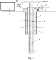
- FIG 1 illustrates a managed pressure drilling system.
- a drillstring 1 is suspended in a wellbore 4 (for purposes of this application the terms wellbore, borehole and well may be used interchangeable).
- an inner annulus 2 also referred to as a drilling annulus
- a first casing string 11 that is hydraulically connected/in fluid communication with an outer annulus 9 through one or more orifices 3.
- the outer annulus 9 may itself be cased/lined by a second casing string 12.
- the depicted concentric casing injection system may be used to inject gas into the wellbore 4 that is being drilled through a subterranean formation.
- the concentric casing injection system comprises the outer annulus 9, which may also be referred to as a gas injection annulus, that surrounds the inner annulus 2, which may also be referred to as a drilling annulus, which drilling annulus is formed between the drillstring 1 disposed in the borehole and the first casing string 1 1 lining the borehole.
- the gas injection annulus comprises an annulus between the first casing string 1 1 the second casing string 12, which may be disposed concentrically around or in a different configuration with respect to the first casing string 1 1 .
- gas is pumped into outer annulus 9 and through one or more gas injection ports 3 into the inner annulus 2.
- the concentric casing injection system may become/be unstable because of among other things the combination of the large volume and compliance of the gas in the outer annulus 9 along with the history dependent hydrostatic head of the inner annulus 2.
- drilling fluid also referred to herein as drilling mud or mud
- drilling fluid may be pumped from a pump(s) (not shown) through pipework 8 into the drillstring 1 , down which it passes until it exits at a distal end 5, through a drill bit (not shown) or the like, before returning via the inner annulus 2 and return pipework 7 to fluid tanks for handling/preparing the drilling fluid.
- a pump(s) not shown
- drillstring 1 down which it passes until it exits at a distal end 5
- drill bit not shown
- fluid tanks for handling/preparing the drilling fluid.
- chokes 13 and separators between the pipework 7 and the fluid tanks (not shown) there may be chokes 13 and separators (not shown).
- the outer annulus 9 and the pipes feeding the top of the drillstring are connected to gas pumps, via a valve manifold 10, which may direct gas either to the drillstring feed, to the outer annulus 9 or optionally to both at once.
- a valve manifold 10 which may direct gas either to the drillstring feed, to the outer annulus 9 or optionally to both at once.
- pressure measurements may be made in the outer annulus 9, the inner annulus 2, the drillstring 1 and/or the like.
- there may be many other pieces of equipment at the surface such as blow-out-preventers, a rotating-control-head etc., which are normal with managed-pressure drilling.
- the system may comprise one or more flow ports between the outer annulus 9 and the inner annulus 2.
- the one or more flow ports may allow drilling mud to flow between the inner annulus 2 and the outer annulus 9.
- mud may be flowing in the inner annulus 2 and may flow through the one or more flow ports into the outer annulus 9.
- pumps and an outflow valve/choke have been controlled to manage the BHP.
- the amount of fluid being pumped into the wellbore has been measured/estimated and the amount of fluid flowing out of the borehole, has been measured/estimated and the pumps/valves/chokes have been adjusted to change the inflow and outflow to maintain the BHP within prescribed limits, or to react to unexpected phenomena in the pressure and/or flowrate.
- characterization of the choke is necessary so that a choke position can be selected to produce the desired outflow from the borehole.
- characterizing the operation of a MPD drilling choke has previously required flowing the liquid to be used in the MPD operation, a drilling fluid, through the choke, which may be either costly or impracticable with respect to chokes that are deployed in the field.
- the choke may be characterized by flowing drilling fluids through the choke to characterize its operation.
- the choke may be taken offline and characterized by flowing drilling fluids through the choke to determine how it operates. Both of these processes are expensive and the in-field characterization may not be practicable.
- An example of flow meters and choke used in the frame MPD operations may be found in international publication WO 2013/005091 A2 .
- drilling fluids which, in general, comprise complex mixtures that provide a range of physical properties
- alternative fluids may be used to characterize the discharge coefficient of MPD flow control valves, and it is even more unexpected that such flow control valves may be characterized using a gas.
- the present invention provides a method for utilising a managed pressure drilling valve in a managed pressure drilling operation, the method comprising calibrating the valve by
- the method may have any one or any combination of the following optional features.
- the pressure drop measurement may be repeated for different air/gas flow rates.
- the velocity measurement may be repeated for different air/gas flow rates.
- the method may further comprise: determining the valve opening position.
- the gas flowing through the valve in step (ii) may be air.
- the managed pressure drilling valve may be a choke.
- the pressure drop across the choke/valve may be controlled so as to avoid compressibility effects in the air/gas flow at least in the region of the flow over which the pressure drop measurement is made. This region will include the choke/valve.
- Measuring a velocity of the air/gas at an inlet of the choke/valve may comprise measuring a flow rate of the air/gas either upstream or downstream of the choke/valve. Making the velocity measurement downstream of the pressure drop measurement can reduce compressibility effects in the pressure drop measurement.
- the pressure drop across the choke/valve may be less than 25%, and preferably less than 20% or 15%, of the absolute pressure at the inlet of the choke/valve.
- the Mach number of the air/gas flow may be less than 0.2, and preferably less than 0.1 so that thermal and compressibility effects in the flow are small.
- the present invention provides managed pressure drilling equipment including means for pumping drilling fluid down a drill string within a borehole, a managed pressure drilling valve to control a flow of the drilling fluid in a managed pressure drilling operation to control the bottom hole pressure, and a system for determining a discharge coefficient of the managed pressure drilling valve as a function of valve opening position, the system comprising:
- the system may have any one or any combination of the following optional features.
- the differential pressure measurement arrangement may comprise a first pressure transducer for measuring a first pressure of the air/gas flow upstream of the choke/valve and a second pressure transducer for measuring a second pressure of the air/gas flow downstream of the choke/valve.
- the pressure drop measurement may be repeated for different valve opening positions and/or different air/gas flow rates.
- the velocity measurement may be repeated for different valve opening positions and/or different air/gas flow rates.
- the device for measuring the velocity of the air/gas flow at the inlet of the managed pressure drilling choke/valve may comprise a flowmeter disposed either upstream or, more preferably, downstream of the choke/valve.
- the source of the air/gas flow may comprise at least one of a compressor, a fan or a blower.
- the source of the air/gas flow may comprise a fan with a power of 1 -2 kW.
- the system may further comprise: a controller for controlling a flow rate of the air/gas flow.
- the controller may control the flow rate (e.g. via a vent line) so that the pressure drop across the choke/valve is less than 25%, and preferably less than 20% or 15%, of the absolute pressure at the inlet of the choke/valve.
- the controller may control the flow rate so that the Mach number of the air/gas flow is less than 0.2, and preferably less than 0.1
- first, second, etc. may be used herein to describe various elements, these elements should not be limited by these terms. These terms are only used to distinguish one element from another.
- a first object or step could be termed a second object or step, and, similarly, a second object or step could be termed a first object or step.
- the first object or step, and the second object or step are both objects or steps, respectively, but they are not to be considered the same object or step.
- the term “if” may be construed to mean “when” or “upon” or “in response to determining” or “in response to detecting,” depending on the context.
- the phrase “if it is determined” or “if [a stated condition or event] is detected” may be construed to mean “upon determining” or “in response to determining” or “upon detecting [the stated condition or event]” or “in response to detecting [the stated condition or event],” depending on the context.
- a usual method to determine the discharge coefficient of a flow rate controlling valve is to calibrate the valve in a test facility using the same fluid as the valve will see in service.
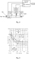
- a diagram of such a calibration system is shown in Figure 2 .
- the pressure and flow rate of the fluid flow returning from the annulus is controlled by a hydraulically actuated valve.
- the discharge coefficient of the valve In order to directly control the flow, i.e., without reactively adjusting the valve in response to outflow measurements made after the position of the valve is changed, the discharge coefficient of the valve must be known as a function of the valve position. Determining the discharge coefficient in the field using the installed hardware (treating iron, triplex pump etc.), the drilling fluids (drilling mud) and available instrumentation (rugged pressure transducers and flowmeters of questionable performance in pulsatile flow) is challenging.
- air/gas is used as the fluid with which the MPD valve/choke is characterized.
- a simple air or gas supply (bottled gas, compressor and/or a fan/blower), a flowmeter (rotameter, portable hotwire or the like) and a pressure transducer(s) may be used to determine the discharge coefficient of the valve as a function of valve opening position.
- the air/gas may be used to determine the discharge coefficient of the valve as a function of valve opening position where a Reynolds number similarity is maintained between the gas/air and the drilling fluid to be used in the MPD and/or a Mach number with respect to the flowing air/gas is small ( ⁇ 0.1), so that thermal and compressibility effects are small.
- FIG. 4 A system for using air/gas to determine the discharge coefficient of the valve as a function of valve opening position is shown in Figure 4 .
- the system has an air/gas supply (fan, blower and/or the like) 20, a vent line 22 to give control of the flow rate, a choke/valve 24 under test, a flowmeter 26 for measuring the velocity of the air/gas flow at the inlet of the choke/valve, a linear variable displacement transducer 28 for determining the chock/valve opening position, and first 30 and second 32 pressure transducers form measuring the pressure drop of the air/gas flow across the choke/valve.
- air/gas supply fan, blower and/or the like
- the maximum pressure drop across the system should not introduce compressibility effects.
- the pressure drop (differential pressure over absolute pressure) across the choke/valve may be limited to less than about 15-25%.
- the flowmeter may be located downstream of the test choke so as to avoid any pressure drop effects produced by the flow meter from impacting on the choke/valve.
- Tables 1 and 2 examples of a valve calibration for both air and water are provided in Tables 1 and 2 below.
- the power shown is the hydraulic power dissipated by the choke, and is representative of the pumping power required for the system.
- the Table 1 shows data for a valve being calibrated using gas and Table 2 shows the valve being calibrated using water.
- the first discharge coefficient C D of 20 corresponds to a 5% valve closing position
- each subsequent C D value corresponds to 10% further closure.
- the last discharge coefficient C D of 10240 corresponds to a 95% valve closing position.
Landscapes
- Engineering & Computer Science (AREA)
- Fluid Mechanics (AREA)
- Physics & Mathematics (AREA)
- Geology (AREA)
- Life Sciences & Earth Sciences (AREA)
- Mining & Mineral Resources (AREA)
- General Physics & Mathematics (AREA)
- Environmental & Geological Engineering (AREA)
- Mechanical Engineering (AREA)
- General Life Sciences & Earth Sciences (AREA)
- Geochemistry & Mineralogy (AREA)
- Flow Control (AREA)
- Earth Drilling (AREA)
- Means For Warming Up And Starting Carburetors (AREA)
- Measuring Volume Flow (AREA)
Claims (16)
- Procédé destiné à l'utilisation d'une vanne de forage sous pression contrôlée (24) dans une opération de forage sous pression contrôlée, le procédé comprenant l'étalonnage de la vanne (24) par :(i) ouverture de la vanne de forage sous pression contrôlée, au moins en partie vers une position d'ouverture de la vanne ;(ii) écoulement d'un gaz à travers la vanne de forage sous pression contrôlée ;(iii) mesure de la vitesse du flux gazeux à l'entrée de la vanne de forage sous pression contrôlée ;(iv) mesure d'une chute de pression du flux gazeux à travers la vanne de forage sous pression contrôlée ;(v) calcul d'un coefficient de décharge correspondant à la position d'ouverture de la vanne à partir de la vitesse mesurée, de la chute de pression mesurée et d'une densité du flux gazeux à l'entrée de la vanne de forage sous pression contrôlée, le coefficient de décharge étant conforme à une formule :
 (vi) répétition des étapes de (i) à (v) pour une ou plusieurs positions d'ouverture de vanne supplémentaires ;
et utilisation de la vanne étalonnée pour réguler un écoulement de fluide de forage dans une opération de forage sous pression contrôlée pour réguler la pression du trou inférieur, le gaz s'écoulant à travers la vanne à l'étape (ii) et le fluide de forage étant de matériaux différents. - Procédé selon la revendication 1, dans lequel la mesure d'une vitesse du flux gazeux à l'entrée de la vanne comprend la mesure du débit de gaz en aval de la vanne.
- Procédé selon la revendication 1 ou la revendication 2, dans lequel la chute de pression à travers la vanne est régulée de manière à éviter les effets de compressibilité dans le flux gazeux au moins dans la région du flux sur laquelle la mesure de la chute de pression est effectuée.
- Procédé selon la revendication 3, dans lequel la chute de pression à travers la vanne est inférieure à 25 % de la pression absolue à l'entrée de la vanne.
- Procédé selon l'une quelconque des revendications 1 à 4, dans lequel une similarité d'un nombre de Reynolds du flux gazeux et d'un nombre de Reynolds de l'écoulement de fluide de forage à utiliser dans le forage sous pression contrôlée est maintenue pendant les étapes d'écoulement et de mesure.
- Procédé selon l'une quelconque des revendications précédentes, dans lequel le nombre de Mach du flux gazeux est inférieur à 0,2.
- Équipement de forage sous pression contrôlée comportant un moyen servant à pomper le fluide de forage vers le bas d'un train de forage (1) à l'intérieur d'un trou de forage (4), une vanne de forage sous pression contrôlée (24) pour réguler un écoulement de fluide de forage dans une opération de forage sous pression contrôlée pour réguler la pression du trou inférieur et un système servant à déterminer le coefficient de décharge de la vanne de forage sous pression contrôlée (24) en fonction de la position d'ouverture de la vanne, le système comprenantun transducteur linéaire à déplacement variable (28) servant à déterminer la position d'ouverture de la vanne de forage sous pression contrôlée ;une source (20) d'un flux gazeux destinée à traverser la vanne de forage sous pression contrôlée ;un système de mesure de pression différentielle (30 32) destiné à mesurer une chute de pression du flux gazeux à travers la vanne de forage sous pression contrôlée ;un dispositif (26) destiné à mesurer la vitesse du flux gazeux à l'entrée de la vanne de forage sous pression contrôlée ; etun processeur configuré pour déterminer le coefficient de décharge de la vanne comme fonction de la position d'ouverture de la vanne à partir de la chute de pression mesurée, de la vitesse mesurée et d'une densité du flux gazeux à l'entrée de la vanne de forage sous pression contrôlée, le coefficient de décharge étant conforme à une formule :

- Équipement selon la revendication 7, dans lequel le système de mesure de pression différentielle comprend un premier transducteur de pression (30) servant à mesurer une première pression du flux gazeux en amont de la vanne et un second transducteur de pression (32) servant à mesurer une seconde pression du flux gazeux en aval de la vanne.
- Équipement selon la revendication 7 ou la revendication 8, dans lequel le dispositif servant à mesurer la vitesse du flux gazeux à l'entrée de la vanne de forage sous pression contrôlée comprend un débitmètre (26) disposé en amont ou en aval de la vanne.
- Équipement selon l'une quelconque des revendications 7 à 9, dans lequel la source du flux gazeux comprend un compresseur, un ventilateur ou une soufflante (20).
- Équipement selon la revendication 10, dans lequel la source du flux gazeux comprend un ventilateur d'une puissance de 1 à 2 kW.
- Équipement selon l'une quelconque des revendications 7 à 11, comprenant en outre un dispositif de commande destiné à réguler un débit du flux gazeux afin de maintenir une similarité entre un nombre de Reynolds du flux gazeux et un nombre de Reynolds du fluide de forage.
- Équipement selon l'une quelconque des revendications 7 à 11, comprenant en outre un dispositif de commande configuré pour réguler un débit du flux gazeux pour obtenir un nombre de Mach inférieur à 0,2.
- Équipement selon la revendication 13 dans lequel le dispositif de commande est configuré pour réguler le débit du flux gazeux pour obtenir un nombre de Mach inférieur à 0,1.
- Procédé selon l'une quelconque des revendications 1 à 6 ou équipement selon l'une quelconque des revendications 7 à 14 dans lequel le gaz est de l'air.
- Procédé selon l'une quelconque des revendications 1 à 6, ou équipement selon l'une quelconque des revendications 7 à 14 dans lequel la vanne de forage sous pression contrôlée (24) est une duse.
Applications Claiming Priority (2)
| Application Number | Priority Date | Filing Date | Title |
|---|---|---|---|
| US201361822146P | 2013-05-10 | 2013-05-10 | |
| PCT/US2014/037744 WO2014183136A1 (fr) | 2013-05-10 | 2014-05-12 | Détermination de coefficient de débit d'une vanne d'étranglement de forage régulée par pression |
Publications (3)
| Publication Number | Publication Date |
|---|---|
| EP2994607A1 EP2994607A1 (fr) | 2016-03-16 |
| EP2994607A4 EP2994607A4 (fr) | 2016-07-13 |
| EP2994607B1 true EP2994607B1 (fr) | 2020-11-18 |
Family
ID=51867806
Family Applications (1)
| Application Number | Title | Priority Date | Filing Date |
|---|---|---|---|
| EP14794648.7A Active EP2994607B1 (fr) | 2013-05-10 | 2014-05-12 | Détermination de coefficient de débit d'une vanne d'étranglement de forage régulée par pression |
Country Status (6)
| Country | Link |
|---|---|
| US (1) | US10533386B2 (fr) |
| EP (1) | EP2994607B1 (fr) |
| BR (1) | BR112015028277A2 (fr) |
| EA (1) | EA201592149A1 (fr) |
| MX (1) | MX370132B (fr) |
| WO (1) | WO2014183136A1 (fr) |
Families Citing this family (13)
| Publication number | Priority date | Publication date | Assignee | Title |
|---|---|---|---|---|
| US10077647B2 (en) | 2014-07-24 | 2018-09-18 | Schlumberger Technology Corporation | Control of a managed pressure drilling system |
| GB2541926B (en) * | 2015-09-04 | 2021-07-14 | Equinor Energy As | System and method for monitoring the state of a choke valve in a managed pressure drilling system |
| CA2920324C (fr) * | 2016-02-08 | 2020-01-07 | Accutron Instruments Inc. | Methode et systeme de mesure de flux d'air ultrasonique |
| US10598527B2 (en) * | 2018-01-29 | 2020-03-24 | Weatherford Technology Holdings, Llc | Differential flow measurement with Coriolis flowmeter |
| US11391103B2 (en) * | 2018-07-05 | 2022-07-19 | Puyang Baifu Reide Petroleum Science And Technology Company Limited | Monitoring, prevention and management method for preventing drilling pump from pump suffocation and misoperation, and pump pressure protection system therefor |
| US11021918B2 (en) | 2018-12-28 | 2021-06-01 | ADS Services LLC | Well control system having one or more adjustable orifice choke valves and method |
| WO2020231996A1 (fr) * | 2019-05-16 | 2020-11-19 | Ameriforge Group Inc. | Forage hydraulique en boucle fermée amélioré |
| US11143540B2 (en) * | 2019-10-28 | 2021-10-12 | Halliburton Energy Services, Inc. | Real time flow rate meter |
| US11220874B2 (en) * | 2020-04-30 | 2022-01-11 | ADS Services LLC | Flow measurement choke valve system |
| WO2021231833A1 (fr) * | 2020-05-14 | 2021-11-18 | Schlumberger Technology Corporation | Système de libération de pression d'espace annulaire |
| US11028648B1 (en) * | 2020-11-05 | 2021-06-08 | Quaise, Inc. | Basement rock hybrid drilling |
| US11643908B1 (en) * | 2021-11-04 | 2023-05-09 | Halliburton Energy Services, Inc. | Automated configuration of pumping equipment |
| EP4433782A4 (fr) * | 2021-11-16 | 2025-10-08 | Services Petroliers Schlumberger | Débitmètre virtuel étalonné |
Citations (4)
| Publication number | Priority date | Publication date | Assignee | Title |
|---|---|---|---|---|
| EP1081472A2 (fr) * | 1999-08-30 | 2001-03-07 | General Electric Company | Procede non-iterative pour obtenir le debit massique |
| WO2001077485A1 (fr) * | 2000-04-11 | 2001-10-18 | Schlumberger Technology Corporation | Debitmetre de fond de trou |
| WO2013005091A2 (fr) * | 2011-07-01 | 2013-01-10 | Schlumberger Technology B.V. | Débitmètre polyphasique |
| WO2013006090A1 (fr) * | 2011-07-07 | 2013-01-10 | Belyaev Boris Mikhailovich | Procédé d'étalonnage mis en oeuvre dans des conditions fonctionnelles pour des débitmètres à ultrasons utilisés pour mesurer le volume et le débit de milieux liquides monophases |
Family Cites Families (7)
| Publication number | Priority date | Publication date | Assignee | Title |
|---|---|---|---|---|
| US4836032A (en) | 1988-03-07 | 1989-06-06 | Texaco, Inc. | Method of determining the quality of steam for stimulating hydrocarbon production |
| US5107441A (en) * | 1990-10-31 | 1992-04-21 | Otis Engineering Corporation | System for evaluating the flow performance characteristics of a device |
| US5226728A (en) * | 1991-11-04 | 1993-07-13 | Badger Meter, Inc. | Method and apparatus for measuring mass flow and energy content using a differential pressure meter |
| US6681189B1 (en) * | 2001-08-22 | 2004-01-20 | The Texas A&M University System | Method and system for determining flow rates and/or fluid density in single and multiple-phase flows utilizing discharge coefficient relationships |
| US7082842B2 (en) | 2004-06-25 | 2006-08-01 | Rivatek Incorporated | Software correction method and apparatus for a variable orifice flow meter |
| US20080011821A1 (en) * | 2006-07-10 | 2008-01-17 | Daniel Measurement And Control, Inc. | Method and System of Determining Orifice Plate Parameters |
| US8633830B2 (en) * | 2010-10-06 | 2014-01-21 | Wixxi Technologies, Llc | Intelligent universal wireless adapter |
-
2014
- 2014-05-12 EA EA201592149A patent/EA201592149A1/ru unknown
- 2014-05-12 MX MX2015015609A patent/MX370132B/es active IP Right Grant
- 2014-05-12 EP EP14794648.7A patent/EP2994607B1/fr active Active
- 2014-05-12 WO PCT/US2014/037744 patent/WO2014183136A1/fr not_active Ceased
- 2014-05-12 US US14/889,709 patent/US10533386B2/en active Active
- 2014-05-12 BR BR112015028277A patent/BR112015028277A2/pt not_active Application Discontinuation
Patent Citations (4)
| Publication number | Priority date | Publication date | Assignee | Title |
|---|---|---|---|---|
| EP1081472A2 (fr) * | 1999-08-30 | 2001-03-07 | General Electric Company | Procede non-iterative pour obtenir le debit massique |
| WO2001077485A1 (fr) * | 2000-04-11 | 2001-10-18 | Schlumberger Technology Corporation | Debitmetre de fond de trou |
| WO2013005091A2 (fr) * | 2011-07-01 | 2013-01-10 | Schlumberger Technology B.V. | Débitmètre polyphasique |
| WO2013006090A1 (fr) * | 2011-07-07 | 2013-01-10 | Belyaev Boris Mikhailovich | Procédé d'étalonnage mis en oeuvre dans des conditions fonctionnelles pour des débitmètres à ultrasons utilisés pour mesurer le volume et le débit de milieux liquides monophases |
Also Published As
| Publication number | Publication date |
|---|---|
| WO2014183136A1 (fr) | 2014-11-13 |
| US10533386B2 (en) | 2020-01-14 |
| EP2994607A4 (fr) | 2016-07-13 |
| US20160076322A1 (en) | 2016-03-17 |
| EA201592149A1 (ru) | 2016-05-31 |
| MX2015015609A (es) | 2016-03-03 |
| MX370132B (es) | 2019-12-03 |
| EP2994607A1 (fr) | 2016-03-16 |
| BR112015028277A2 (pt) | 2019-10-01 |
Similar Documents
| Publication | Publication Date | Title |
|---|---|---|
| EP2994607B1 (fr) | Détermination de coefficient de débit d'une vanne d'étranglement de forage régulée par pression | |
| US9581475B2 (en) | Multiphase flowmeter | |
| EP3169871B1 (fr) | Outil de puits à débitmètre | |
| US8567525B2 (en) | Method for determining fluid control events in a borehole using a dynamic annular pressure control system | |
| AU2007205225B2 (en) | Method for determining formation fluid entry into or drilling fluid loss from a borehole using a dynamic annular pressure control system | |
| CN103270242B (zh) | 用于钻探地下井眼的方法和设备 | |
| US6378628B1 (en) | Monitoring system for drilling operations | |
| US20070246263A1 (en) | Pressure Safety System for Use With a Dynamic Annular Pressure Control System | |
| US20070227774A1 (en) | Method for Controlling Fluid Pressure in a Borehole Using a Dynamic Annular Pressure Control System | |
| CA2829378A1 (fr) | Procede de caracterisation de formations souterraines utilisant une reponse de pression de fluide pendant des operations de forage | |
| BR112014013215B1 (pt) | método de perfuração de poço | |
| CN103180541A (zh) | 控制压力钻井设备 | |
| US10077647B2 (en) | Control of a managed pressure drilling system | |
| US10982516B2 (en) | Systems and methods for operating downhole inflow control valves to provide sufficient pump intake pressure | |
| US20160230484A1 (en) | Wellbore hydraulic compliance | |
| US9284799B2 (en) | Method for drilling through nuisance hydrocarbon bearing formations | |
| EP3559408A1 (fr) | Signal de pression utilisé pour déterminer un volume d'espace annulaire | |
| SA113340678B1 (ar) | التحكم في الضغط في عمليات الحفر مع الإزاحة المطبقة استجابة لظروف محددة سلفاً | |
| Xian et al. | A new method of BHP measurement in ESP deadhead test |
Legal Events
| Date | Code | Title | Description |
|---|---|---|---|
| PUAI | Public reference made under article 153(3) epc to a published international application that has entered the european phase |
Free format text: ORIGINAL CODE: 0009012 |
|
| 17P | Request for examination filed |
Effective date: 20151030 |
|
| AK | Designated contracting states |
Kind code of ref document: A1 Designated state(s): AL AT BE BG CH CY CZ DE DK EE ES FI FR GB GR HR HU IE IS IT LI LT LU LV MC MK MT NL NO PL PT RO RS SE SI SK SM TR |
|
| AX | Request for extension of the european patent |
Extension state: BA ME |
|
| A4 | Supplementary search report drawn up and despatched |
Effective date: 20160613 |
|
| RIC1 | Information provided on ipc code assigned before grant |
Ipc: E21B 21/08 20060101ALN20160607BHEP Ipc: E21B 34/02 20060101AFI20160607BHEP Ipc: E21B 21/10 20060101ALI20160607BHEP Ipc: E21B 43/12 20060101ALI20160607BHEP Ipc: G01F 25/00 20060101ALI20160607BHEP |
|
| 17Q | First examination report despatched |
Effective date: 20160704 |
|
| DAX | Request for extension of the european patent (deleted) | ||
| STAA | Information on the status of an ep patent application or granted ep patent |
Free format text: STATUS: EXAMINATION IS IN PROGRESS |
|
| GRAP | Despatch of communication of intention to grant a patent |
Free format text: ORIGINAL CODE: EPIDOSNIGR1 |
|
| STAA | Information on the status of an ep patent application or granted ep patent |
Free format text: STATUS: GRANT OF PATENT IS INTENDED |
|
| RIC1 | Information provided on ipc code assigned before grant |
Ipc: E21B 21/08 20060101ALN20200515BHEP Ipc: G01F 25/00 20060101ALI20200515BHEP Ipc: E21B 43/12 20060101ALI20200515BHEP Ipc: E21B 34/02 20060101AFI20200515BHEP Ipc: E21B 21/10 20060101ALI20200515BHEP |
|
| INTG | Intention to grant announced |
Effective date: 20200619 |
|
| GRAS | Grant fee paid |
Free format text: ORIGINAL CODE: EPIDOSNIGR3 |
|
| GRAA | (expected) grant |
Free format text: ORIGINAL CODE: 0009210 |
|
| STAA | Information on the status of an ep patent application or granted ep patent |
Free format text: STATUS: THE PATENT HAS BEEN GRANTED |
|
| AK | Designated contracting states |
Kind code of ref document: B1 Designated state(s): AL AT BE BG CH CY CZ DE DK EE ES FI FR GB GR HR HU IE IS IT LI LT LU LV MC MK MT NL NO PL PT RO RS SE SI SK SM TR |
|
| REG | Reference to a national code |
Ref country code: GB Ref legal event code: FG4D |
|
| REG | Reference to a national code |
Ref country code: CH Ref legal event code: EP |
|
| REG | Reference to a national code |
Ref country code: DE Ref legal event code: R096 Ref document number: 602014072503 Country of ref document: DE |
|
| REG | Reference to a national code |
Ref country code: IE Ref legal event code: FG4D |
|
| REG | Reference to a national code |
Ref country code: AT Ref legal event code: REF Ref document number: 1335979 Country of ref document: AT Kind code of ref document: T Effective date: 20201215 |
|
| REG | Reference to a national code |
Ref country code: AT Ref legal event code: MK05 Ref document number: 1335979 Country of ref document: AT Kind code of ref document: T Effective date: 20201118 |
|
| REG | Reference to a national code |
Ref country code: NL Ref legal event code: MP Effective date: 20201118 |
|
| REG | Reference to a national code |
Ref country code: NO Ref legal event code: T2 Effective date: 20201118 |
|
| PG25 | Lapsed in a contracting state [announced via postgrant information from national office to epo] |
Ref country code: GR Free format text: LAPSE BECAUSE OF FAILURE TO SUBMIT A TRANSLATION OF THE DESCRIPTION OR TO PAY THE FEE WITHIN THE PRESCRIBED TIME-LIMIT Effective date: 20210219 Ref country code: PT Free format text: LAPSE BECAUSE OF FAILURE TO SUBMIT A TRANSLATION OF THE DESCRIPTION OR TO PAY THE FEE WITHIN THE PRESCRIBED TIME-LIMIT Effective date: 20210318 Ref country code: FI Free format text: LAPSE BECAUSE OF FAILURE TO SUBMIT A TRANSLATION OF THE DESCRIPTION OR TO PAY THE FEE WITHIN THE PRESCRIBED TIME-LIMIT Effective date: 20201118 Ref country code: RS Free format text: LAPSE BECAUSE OF FAILURE TO SUBMIT A TRANSLATION OF THE DESCRIPTION OR TO PAY THE FEE WITHIN THE PRESCRIBED TIME-LIMIT Effective date: 20201118 |
|
| PG25 | Lapsed in a contracting state [announced via postgrant information from national office to epo] |
Ref country code: IS Free format text: LAPSE BECAUSE OF FAILURE TO SUBMIT A TRANSLATION OF THE DESCRIPTION OR TO PAY THE FEE WITHIN THE PRESCRIBED TIME-LIMIT Effective date: 20210318 Ref country code: LV Free format text: LAPSE BECAUSE OF FAILURE TO SUBMIT A TRANSLATION OF THE DESCRIPTION OR TO PAY THE FEE WITHIN THE PRESCRIBED TIME-LIMIT Effective date: 20201118 Ref country code: PL Free format text: LAPSE BECAUSE OF FAILURE TO SUBMIT A TRANSLATION OF THE DESCRIPTION OR TO PAY THE FEE WITHIN THE PRESCRIBED TIME-LIMIT Effective date: 20201118 Ref country code: SE Free format text: LAPSE BECAUSE OF FAILURE TO SUBMIT A TRANSLATION OF THE DESCRIPTION OR TO PAY THE FEE WITHIN THE PRESCRIBED TIME-LIMIT Effective date: 20201118 Ref country code: BG Free format text: LAPSE BECAUSE OF FAILURE TO SUBMIT A TRANSLATION OF THE DESCRIPTION OR TO PAY THE FEE WITHIN THE PRESCRIBED TIME-LIMIT Effective date: 20210218 Ref country code: AT Free format text: LAPSE BECAUSE OF FAILURE TO SUBMIT A TRANSLATION OF THE DESCRIPTION OR TO PAY THE FEE WITHIN THE PRESCRIBED TIME-LIMIT Effective date: 20201118 |
|
| REG | Reference to a national code |
Ref country code: LT Ref legal event code: MG9D |
|
| PG25 | Lapsed in a contracting state [announced via postgrant information from national office to epo] |
Ref country code: HR Free format text: LAPSE BECAUSE OF FAILURE TO SUBMIT A TRANSLATION OF THE DESCRIPTION OR TO PAY THE FEE WITHIN THE PRESCRIBED TIME-LIMIT Effective date: 20201118 |
|
| PG25 | Lapsed in a contracting state [announced via postgrant information from national office to epo] |
Ref country code: RO Free format text: LAPSE BECAUSE OF FAILURE TO SUBMIT A TRANSLATION OF THE DESCRIPTION OR TO PAY THE FEE WITHIN THE PRESCRIBED TIME-LIMIT Effective date: 20201118 Ref country code: SK Free format text: LAPSE BECAUSE OF FAILURE TO SUBMIT A TRANSLATION OF THE DESCRIPTION OR TO PAY THE FEE WITHIN THE PRESCRIBED TIME-LIMIT Effective date: 20201118 Ref country code: LT Free format text: LAPSE BECAUSE OF FAILURE TO SUBMIT A TRANSLATION OF THE DESCRIPTION OR TO PAY THE FEE WITHIN THE PRESCRIBED TIME-LIMIT Effective date: 20201118 Ref country code: EE Free format text: LAPSE BECAUSE OF FAILURE TO SUBMIT A TRANSLATION OF THE DESCRIPTION OR TO PAY THE FEE WITHIN THE PRESCRIBED TIME-LIMIT Effective date: 20201118 Ref country code: CZ Free format text: LAPSE BECAUSE OF FAILURE TO SUBMIT A TRANSLATION OF THE DESCRIPTION OR TO PAY THE FEE WITHIN THE PRESCRIBED TIME-LIMIT Effective date: 20201118 Ref country code: SM Free format text: LAPSE BECAUSE OF FAILURE TO SUBMIT A TRANSLATION OF THE DESCRIPTION OR TO PAY THE FEE WITHIN THE PRESCRIBED TIME-LIMIT Effective date: 20201118 |
|
| REG | Reference to a national code |
Ref country code: DE Ref legal event code: R097 Ref document number: 602014072503 Country of ref document: DE |
|
| PG25 | Lapsed in a contracting state [announced via postgrant information from national office to epo] |
Ref country code: DK Free format text: LAPSE BECAUSE OF FAILURE TO SUBMIT A TRANSLATION OF THE DESCRIPTION OR TO PAY THE FEE WITHIN THE PRESCRIBED TIME-LIMIT Effective date: 20201118 |
|
| PLBE | No opposition filed within time limit |
Free format text: ORIGINAL CODE: 0009261 |
|
| STAA | Information on the status of an ep patent application or granted ep patent |
Free format text: STATUS: NO OPPOSITION FILED WITHIN TIME LIMIT |
|
| 26N | No opposition filed |
Effective date: 20210819 |
|
| PG25 | Lapsed in a contracting state [announced via postgrant information from national office to epo] |
Ref country code: AL Free format text: LAPSE BECAUSE OF FAILURE TO SUBMIT A TRANSLATION OF THE DESCRIPTION OR TO PAY THE FEE WITHIN THE PRESCRIBED TIME-LIMIT Effective date: 20201118 Ref country code: NL Free format text: LAPSE BECAUSE OF FAILURE TO SUBMIT A TRANSLATION OF THE DESCRIPTION OR TO PAY THE FEE WITHIN THE PRESCRIBED TIME-LIMIT Effective date: 20201118 Ref country code: IT Free format text: LAPSE BECAUSE OF FAILURE TO SUBMIT A TRANSLATION OF THE DESCRIPTION OR TO PAY THE FEE WITHIN THE PRESCRIBED TIME-LIMIT Effective date: 20201118 |
|
| PG25 | Lapsed in a contracting state [announced via postgrant information from national office to epo] |
Ref country code: ES Free format text: LAPSE BECAUSE OF FAILURE TO SUBMIT A TRANSLATION OF THE DESCRIPTION OR TO PAY THE FEE WITHIN THE PRESCRIBED TIME-LIMIT Effective date: 20201118 Ref country code: SI Free format text: LAPSE BECAUSE OF FAILURE TO SUBMIT A TRANSLATION OF THE DESCRIPTION OR TO PAY THE FEE WITHIN THE PRESCRIBED TIME-LIMIT Effective date: 20201118 |
|
| REG | Reference to a national code |
Ref country code: DE Ref legal event code: R119 Ref document number: 602014072503 Country of ref document: DE |
|
| REG | Reference to a national code |
Ref country code: CH Ref legal event code: PL |
|
| PG25 | Lapsed in a contracting state [announced via postgrant information from national office to epo] |
Ref country code: CH Free format text: LAPSE BECAUSE OF NON-PAYMENT OF DUE FEES Effective date: 20210531 Ref country code: LI Free format text: LAPSE BECAUSE OF NON-PAYMENT OF DUE FEES Effective date: 20210531 Ref country code: MC Free format text: LAPSE BECAUSE OF FAILURE TO SUBMIT A TRANSLATION OF THE DESCRIPTION OR TO PAY THE FEE WITHIN THE PRESCRIBED TIME-LIMIT Effective date: 20201118 Ref country code: LU Free format text: LAPSE BECAUSE OF NON-PAYMENT OF DUE FEES Effective date: 20210512 |
|
| REG | Reference to a national code |
Ref country code: BE Ref legal event code: MM Effective date: 20210531 |
|
| PG25 | Lapsed in a contracting state [announced via postgrant information from national office to epo] |
Ref country code: IE Free format text: LAPSE BECAUSE OF NON-PAYMENT OF DUE FEES Effective date: 20210512 Ref country code: DE Free format text: LAPSE BECAUSE OF NON-PAYMENT OF DUE FEES Effective date: 20211201 |
|
| PG25 | Lapsed in a contracting state [announced via postgrant information from national office to epo] |
Ref country code: IS Free format text: LAPSE BECAUSE OF FAILURE TO SUBMIT A TRANSLATION OF THE DESCRIPTION OR TO PAY THE FEE WITHIN THE PRESCRIBED TIME-LIMIT Effective date: 20210318 Ref country code: FR Free format text: LAPSE BECAUSE OF NON-PAYMENT OF DUE FEES Effective date: 20210531 |
|
| PG25 | Lapsed in a contracting state [announced via postgrant information from national office to epo] |
Ref country code: BE Free format text: LAPSE BECAUSE OF NON-PAYMENT OF DUE FEES Effective date: 20210531 |
|
| PG25 | Lapsed in a contracting state [announced via postgrant information from national office to epo] |
Ref country code: HU Free format text: LAPSE BECAUSE OF FAILURE TO SUBMIT A TRANSLATION OF THE DESCRIPTION OR TO PAY THE FEE WITHIN THE PRESCRIBED TIME-LIMIT; INVALID AB INITIO Effective date: 20140512 |
|
| PG25 | Lapsed in a contracting state [announced via postgrant information from national office to epo] |
Ref country code: CY Free format text: LAPSE BECAUSE OF FAILURE TO SUBMIT A TRANSLATION OF THE DESCRIPTION OR TO PAY THE FEE WITHIN THE PRESCRIBED TIME-LIMIT Effective date: 20201118 |
|
| P01 | Opt-out of the competence of the unified patent court (upc) registered |
Effective date: 20231208 |
|
| PG25 | Lapsed in a contracting state [announced via postgrant information from national office to epo] |
Ref country code: MK Free format text: LAPSE BECAUSE OF FAILURE TO SUBMIT A TRANSLATION OF THE DESCRIPTION OR TO PAY THE FEE WITHIN THE PRESCRIBED TIME-LIMIT Effective date: 20201118 |
|
| PG25 | Lapsed in a contracting state [announced via postgrant information from national office to epo] |
Ref country code: MT Free format text: LAPSE BECAUSE OF FAILURE TO SUBMIT A TRANSLATION OF THE DESCRIPTION OR TO PAY THE FEE WITHIN THE PRESCRIBED TIME-LIMIT Effective date: 20201118 |
|
| PGFP | Annual fee paid to national office [announced via postgrant information from national office to epo] |
Ref country code: NO Payment date: 20250509 Year of fee payment: 12 |
|
| PG25 | Lapsed in a contracting state [announced via postgrant information from national office to epo] |
Ref country code: TR Free format text: LAPSE BECAUSE OF FAILURE TO SUBMIT A TRANSLATION OF THE DESCRIPTION OR TO PAY THE FEE WITHIN THE PRESCRIBED TIME-LIMIT Effective date: 20201118 |
|
| PGFP | Annual fee paid to national office [announced via postgrant information from national office to epo] |
Ref country code: GB Payment date: 20260324 Year of fee payment: 13 |