EP2994672B1 - Vanne piézoélectrique proportionnelle numérique linéaire - Google Patents
Vanne piézoélectrique proportionnelle numérique linéaire Download PDFInfo
- Publication number
- EP2994672B1 EP2994672B1 EP14722780.5A EP14722780A EP2994672B1 EP 2994672 B1 EP2994672 B1 EP 2994672B1 EP 14722780 A EP14722780 A EP 14722780A EP 2994672 B1 EP2994672 B1 EP 2994672B1
- Authority
- EP
- European Patent Office
- Prior art keywords
- shaft
- valve
- speed
- follower
- valve member
- Prior art date
- Legal status (The legal status is an assumption and is not a legal conclusion. Google has not performed a legal analysis and makes no representation as to the accuracy of the status listed.)
- Active
Links
Images


Classifications
-
- F—MECHANICAL ENGINEERING; LIGHTING; HEATING; WEAPONS; BLASTING
- F16—ENGINEERING ELEMENTS AND UNITS; GENERAL MEASURES FOR PRODUCING AND MAINTAINING EFFECTIVE FUNCTIONING OF MACHINES OR INSTALLATIONS; THERMAL INSULATION IN GENERAL
- F16K—VALVES; TAPS; COCKS; ACTUATING-FLOATS; DEVICES FOR VENTING OR AERATING
- F16K31/00—Actuating devices; Operating means; Releasing devices
- F16K31/004—Actuating devices; Operating means; Releasing devices actuated by piezoelectric means
-
- F—MECHANICAL ENGINEERING; LIGHTING; HEATING; WEAPONS; BLASTING
- F16—ENGINEERING ELEMENTS AND UNITS; GENERAL MEASURES FOR PRODUCING AND MAINTAINING EFFECTIVE FUNCTIONING OF MACHINES OR INSTALLATIONS; THERMAL INSULATION IN GENERAL
- F16K—VALVES; TAPS; COCKS; ACTUATING-FLOATS; DEVICES FOR VENTING OR AERATING
- F16K11/00—Multiple-way valves, e.g. mixing valves; Pipe fittings incorporating such valves
- F16K11/02—Multiple-way valves, e.g. mixing valves; Pipe fittings incorporating such valves with all movable sealing faces moving as one unit
- F16K11/04—Multiple-way valves, e.g. mixing valves; Pipe fittings incorporating such valves with all movable sealing faces moving as one unit comprising only lift valves
- F16K11/044—Multiple-way valves, e.g. mixing valves; Pipe fittings incorporating such valves with all movable sealing faces moving as one unit comprising only lift valves with movable valve members positioned between valve seats
-
- F—MECHANICAL ENGINEERING; LIGHTING; HEATING; WEAPONS; BLASTING
- F16—ENGINEERING ELEMENTS AND UNITS; GENERAL MEASURES FOR PRODUCING AND MAINTAINING EFFECTIVE FUNCTIONING OF MACHINES OR INSTALLATIONS; THERMAL INSULATION IN GENERAL
- F16K—VALVES; TAPS; COCKS; ACTUATING-FLOATS; DEVICES FOR VENTING OR AERATING
- F16K1/00—Lift valves or globe valves, i.e. cut-off apparatus with closure members having at least a component of their opening and closing motion perpendicular to the closing faces
- F16K1/32—Details
- F16K1/52—Means for additional adjustment of the rate of flow
-
- A—HUMAN NECESSITIES
- A61—MEDICAL OR VETERINARY SCIENCE; HYGIENE
- A61B—DIAGNOSIS; SURGERY; IDENTIFICATION
- A61B5/00—Measuring for diagnostic purposes; Identification of persons
- A61B5/02—Detecting, measuring or recording for evaluating the cardiovascular system, e.g. pulse, heart rate, blood pressure or blood flow
- A61B5/021—Measuring pressure in heart or blood vessels
- A61B5/022—Measuring pressure in heart or blood vessels by applying pressure to close blood vessels, e.g. against the skin; Ophthalmodynamometers
- A61B5/0235—Valves specially adapted therefor
-
- A—HUMAN NECESSITIES
- A61—MEDICAL OR VETERINARY SCIENCE; HYGIENE
- A61M—DEVICES FOR INTRODUCING MEDIA INTO, OR ONTO, THE BODY; DEVICES FOR TRANSDUCING BODY MEDIA OR FOR TAKING MEDIA FROM THE BODY; DEVICES FOR PRODUCING OR ENDING SLEEP OR STUPOR
- A61M16/00—Devices for influencing the respiratory system of patients by gas treatment, e.g. ventilators; Tracheal tubes
- A61M16/20—Valves specially adapted to medical respiratory devices
- A61M16/201—Controlled valves
- A61M16/202—Controlled valves electrically actuated
- A61M16/203—Proportional
-
- F—MECHANICAL ENGINEERING; LIGHTING; HEATING; WEAPONS; BLASTING
- F16—ENGINEERING ELEMENTS AND UNITS; GENERAL MEASURES FOR PRODUCING AND MAINTAINING EFFECTIVE FUNCTIONING OF MACHINES OR INSTALLATIONS; THERMAL INSULATION IN GENERAL
- F16K—VALVES; TAPS; COCKS; ACTUATING-FLOATS; DEVICES FOR VENTING OR AERATING
- F16K1/00—Lift valves or globe valves, i.e. cut-off apparatus with closure members having at least a component of their opening and closing motion perpendicular to the closing faces
- F16K1/32—Details
- F16K1/34—Cutting-off parts, e.g. valve members, seats
- F16K1/44—Details of seats or valve members of double-seat valves
- F16K1/443—Details of seats or valve members of double-seat valves the seats being in series
-
- F—MECHANICAL ENGINEERING; LIGHTING; HEATING; WEAPONS; BLASTING
- F16—ENGINEERING ELEMENTS AND UNITS; GENERAL MEASURES FOR PRODUCING AND MAINTAINING EFFECTIVE FUNCTIONING OF MACHINES OR INSTALLATIONS; THERMAL INSULATION IN GENERAL
- F16K—VALVES; TAPS; COCKS; ACTUATING-FLOATS; DEVICES FOR VENTING OR AERATING
- F16K31/00—Actuating devices; Operating means; Releasing devices
- F16K31/004—Actuating devices; Operating means; Releasing devices actuated by piezoelectric means
- F16K31/005—Piezoelectric benders
-
- F—MECHANICAL ENGINEERING; LIGHTING; HEATING; WEAPONS; BLASTING
- F16—ENGINEERING ELEMENTS AND UNITS; GENERAL MEASURES FOR PRODUCING AND MAINTAINING EFFECTIVE FUNCTIONING OF MACHINES OR INSTALLATIONS; THERMAL INSULATION IN GENERAL
- F16K—VALVES; TAPS; COCKS; ACTUATING-FLOATS; DEVICES FOR VENTING OR AERATING
- F16K31/00—Actuating devices; Operating means; Releasing devices
- F16K31/02—Actuating devices; Operating means; Releasing devices electric; magnetic
-
- G—PHYSICS
- G01—MEASURING; TESTING
- G01R—MEASURING ELECTRIC VARIABLES; MEASURING MAGNETIC VARIABLES
- G01R33/00—Arrangements or instruments for measuring magnetic variables
- G01R33/20—Arrangements or instruments for measuring magnetic variables involving magnetic resonance
- G01R33/28—Details of apparatus provided for in groups G01R33/44 - G01R33/64
-
- A—HUMAN NECESSITIES
- A61—MEDICAL OR VETERINARY SCIENCE; HYGIENE
- A61B—DIAGNOSIS; SURGERY; IDENTIFICATION
- A61B2503/00—Evaluating a particular growth phase or type of persons or animals
- A61B2503/04—Babies, e.g. for SIDS detection
- A61B2503/045—Newborns, e.g. premature baby monitoring
-
- A—HUMAN NECESSITIES
- A61—MEDICAL OR VETERINARY SCIENCE; HYGIENE
- A61B—DIAGNOSIS; SURGERY; IDENTIFICATION
- A61B2505/00—Evaluating, monitoring or diagnosing in the context of a particular type of medical care
- A61B2505/05—Surgical care
-
- A—HUMAN NECESSITIES
- A61—MEDICAL OR VETERINARY SCIENCE; HYGIENE
- A61B—DIAGNOSIS; SURGERY; IDENTIFICATION
- A61B5/00—Measuring for diagnostic purposes; Identification of persons
- A61B5/08—Measuring devices for evaluating the respiratory organs
- A61B5/082—Evaluation by breath analysis, e.g. determination of the chemical composition of exhaled breath
-
- A—HUMAN NECESSITIES
- A61—MEDICAL OR VETERINARY SCIENCE; HYGIENE
- A61M—DEVICES FOR INTRODUCING MEDIA INTO, OR ONTO, THE BODY; DEVICES FOR TRANSDUCING BODY MEDIA OR FOR TAKING MEDIA FROM THE BODY; DEVICES FOR PRODUCING OR ENDING SLEEP OR STUPOR
- A61M16/00—Devices for influencing the respiratory system of patients by gas treatment, e.g. ventilators; Tracheal tubes
- A61M16/01—Devices for influencing the respiratory system of patients by gas treatment, e.g. ventilators; Tracheal tubes specially adapted for anaesthetising
-
- A—HUMAN NECESSITIES
- A61—MEDICAL OR VETERINARY SCIENCE; HYGIENE
- A61M—DEVICES FOR INTRODUCING MEDIA INTO, OR ONTO, THE BODY; DEVICES FOR TRANSDUCING BODY MEDIA OR FOR TAKING MEDIA FROM THE BODY; DEVICES FOR PRODUCING OR ENDING SLEEP OR STUPOR
- A61M2205/00—General characteristics of the apparatus
- A61M2205/05—General characteristics of the apparatus combined with other kinds of therapy
- A61M2205/057—General characteristics of the apparatus combined with other kinds of therapy with magnetotherapy
-
- A—HUMAN NECESSITIES
- A61—MEDICAL OR VETERINARY SCIENCE; HYGIENE
- A61M—DEVICES FOR INTRODUCING MEDIA INTO, OR ONTO, THE BODY; DEVICES FOR TRANSDUCING BODY MEDIA OR FOR TAKING MEDIA FROM THE BODY; DEVICES FOR PRODUCING OR ENDING SLEEP OR STUPOR
- A61M2230/00—Measuring parameters of the user
- A61M2230/30—Blood pressure
Definitions
- the following relates generally to electrically controlled valves which can operate in a strong magnetic field. It finds particular application in conjunction with low-pressure fluid valves which operate near a magnetic resonance imaging scanner, and will be described with particular reference thereto. However, it will be understood that it also finds application in other usage scenarios and is not necessarily limited to the aforementioned application.
- Valves which operate in a strong magnetic field include non-magnetic materials or are designed such that the magnetic materials are removed or shielded from the magnetic field. The presence of magnetic materials can affect operation of the valve device and can potentially act as projectiles. Valves are used for controlling fluids such as anesthesia gas supply during magnetic resonance guided surgery, air pressure control in non-invasive blood pressure (NIBP) monitoring, oxygen supply for patient life support, measuring patient gas expiration, and the like.
- NIBP non-invasive blood pressure
- One acute area of need includes neonatal applications where volumes of gas are small and close adjustment of fluid flow is important.
- One approach is to use a valve switched pneumatically from a traditional valve location outside the magnetic field, e.g. located outside a shielded room with pneumatic connections.
- the disadvantage is the use of a compressed air supply, bulky pneumatic tubing, and noise.
- Another approach is the use of shielding to shield ferrous valve parts from external magnetic fields.
- shielding makes use of ferrous materials such as iron which make the shielding subject to distorting the magnetic field and becoming potentially projectiles.
- Valves typically include a spring or biasing element which biases the valve by default either open or closed.
- Springs materials subject to the strong magnetic fields, and in some instances, can collapse under the magnetic forces.
- springs can be made from non-magnetic materials such as beryllium-copper or phosphor-bronze but the material is costly. Furthermore, the non-magnetic materials can be found to change their spring constant over time which makes them less reliable in medical care applications.
- valve materials which are not subject to the magnetic field.
- piezoelectric diaphragm valves are used, but are typically physically large and need very high drive voltages.
- the diaphragm includes a covering of piezoelectric material which operates to change shape and directly open or close a valve port when an electrical charge is applied.
- the high voltage drivers are expensive and difficult to implement in magnetic field because they often have components which are also subject the magnetic field.
- piezoelectric bending actuators such as a flap which bends to directly open or close a valve.
- Both examples include a spring element or biasing element which is subject to wear and difficult to replace and/or repair.
- Both examples include a valve which operates in analog manner between the valve being either completely open or completely closed.
- JP 2-112669 discloses a valve for controlling the idle rotational speed of an engine by bypassing the throttle valve. It uses multiple piezoelectric bodies to create an ultrasonic traveling wave which causes movement of the control valve.
- an electrically controlled valve includes a shaft, a piezoelectric motor affixed to an end of the shaft, a controller, a follower, a valve member, and a valve seat.
- the piezoelectric motor drives the shaft with a first direction and a second opposite direction.
- the controller provides power to the piezoelectric motor to move the shaft with a first speed and a second speed, the first speed being faster that the second speed.
- the follower receives the shaft, and slides relative to the shaft in response to the shaft moving with the first speed, and grips and moves with the shaft in response to the moving with the second speed and includes a valve member.
- the valve member moves with the follower.
- the valve member is configured to be moved by the follower against the valve seat to restrict fluid flow and to be moved by the follower away from the valve seat to increase the fluid flow.
- a method of fluid control includes applying electrical pulses to a piezoelectric motor which moves a shaft affixed to the piezoelectric motor to move the shaft with a first speed and a second speed, the first speed being faster than the second speed.
- the shaft is moved with the first speed such that a follower which receives the shaft slides relative to the shaft.
- the shaft is moved with the second speed such that the follower grips the shaft and moves with the shaft.
- Pulses are repeatedly applied to alternately move the shaft toward a valve seat at the second speed and away from the valve seat at the first speed to move a valve member which moves with the follower against a valve seat to restrict fluid flow. Pulses are repeatedly applied to alternately move the shaft toward a valve seat at the first speed and away from the valve seat at the second speed to move the valve member which moves with the follower away from the valve seat to increase fluid flow.
- the follower allows the rod to overcome friction forces with the follower with a first force applied to the rod and slide along the rod, and to grip and move with the rod in response to a second applied opposing force.
- the valve element defines a central well shaped cavity to receive the rod.
- the magnetic field inert housing defines a cavity that holds the follower and the valve element, receives the rod, and defines a first port connected to the cavity, a second port connected to the cavity, and a seat.
- the first port receives fluid inflow.
- the second port outflows the received fluid.
- the seat receives the valve member and restricts the fluid flow between the first port and the second port proportional to the distance from the valve member to the seat.
- One advantage is low power consumption.
- Another advantage includes a low hysteresis.
- Another advantage resides in a low cost of manufacture.
- Another advantage resides in low back pressure and low differential pressure. Another advantage resides in ease of control without voltage control.
- Another advantage resides in digital operation, particularly digital control of a degree to which the valve is open.
- Another advantage resides in the simple construction without a spring or biasing element.
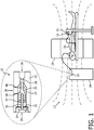
- FIGURE 1 an embodiment of a linear digital proportional piezoelectric valve 10 in a strong magnetic field 12 with an exploded cross section view of the linear digital proportional piezoelectric valve is schematically illustrated.
- Two medical devices are shown, by way of example, with the linear digital proportional piezoelectric valve 10, an anesthesia device 14 and a non-invasive blood pressure (NIBP) measuring device 16.
- a magnetic resonance scanner 18 is shown in partial cross section which generates strong magnetic fields such as a static main magnetic field B 0 , gradient magnetic fields, RF pulses B 1 , and the like.
- Typical applications of the linear digital proportional piezoelectric valve include regulating the delivery of fluids such as anesthetic gases to a subject 20, monitoring gases expired by the subject, monitoring NIBP, and the like.
- the illustrated valve is designed to operate up to about 0.68 atm (10 psi; 0.69 bar) which makes it suitable for these types of applications.
- the application can include regulating gases for neonatal applications such as NIBP which differ from adult NI
- the valve 10 includes a valve housing 22 of MR inert material such as plastic.
- the housing 22 defines an internal cavity 24 with two ports 26, one for inflow of fluids such as anesthetic gases, respiratory gases, air, etc. and one for outflow.
- the ports can operate in either direction.
- the base defines a valve seat 28 and an access opening 30 covered by a bonnet 32 .
- the cavity receives a valve element 33 through the access opening, e.g. the valve member is positioned within the cavity 24.
- the valve element defines a central well shaped cavity 38 to receive a drive rod 36.
- a piezoelectric motor 34 is affixed to an end of the drive rod or shaft 36 opposite the follower and the rod passes through an opening in the seal into an interior of the valve element 33.
- the motor and rod form a nail shape with piezoelectric material affixed to a surface of the nail head.
- the piezoelectric motor drives the rod based on received pulses of electric current with a first current intensity which applies a first force to the rod and a second current intensity which applies an opposing second force to the rod.
- a first current intensity flexes piezoelectric material quickly which applies a first force to the rod.
- a second current intensity flattens the piezoelectric material slowly which applies an opposing second force to the rod.
- a first current intensity flexes the piezoelectric material slowly which applies one force
- a second current intensity flattens the piezoelectric material quickly which applies another opposing force.
- the rod 36 can include materials such as copper, aluminum, and the like.
- a follower 42 moves linearly along the length of the rod driven by the piezoelectric motor to open or close the valve 10.
- the valve seat 28 receives a valve member 40, such as an O-ring and restricts the fluid flow between the ports proportional to a displacement between the valve member 40 to the valve seat 28.
- the valve is fully closed with the valve member compressed against the seat.
- the valve can be partially opened by applying a fixed number of electrical pulses to the piezoelectric motor to partially open the valve.
- the valve can be fully open by the movement of the follower such that the end of the rod opposite the piezoelectric motor engages the bottom of the well 38 defined in the valve element.
- the position of follower with the rod engaging the well bottom fully opens the valve and permits fluid flow between the ports.
- the drawing depicts the valve in a fully open configuration.
- the follower 42 which slides along the rod 36 in response to a force exerted by the piezoelectric motor on the rod which overcomes friction, such as with fast flexing or fast flattening of the piezoelectric material.
- the follower 42 grips and moves with the rod 36 in response to a force exerted by the piezoelectric motor which moves the rod with insufficient speed to overcome friction such as with slow flexing or slow flattening of the piezoelectric material.
- the follower 42 attaches to the valve element 33 and is located circumferentially and frictionally engaging the rod 36 .
- the follower 42 can include material such as tin, copper, brass, rubber, plastic and the like.
- valve 10 is schematically illustrated in cross section.
- the valve 10 is shown in a fully closed configuration where the valve member 40 is received by the seat 28 and restricts the flow between the ports 26.
- the seat 28 and the valve member 40 can be tapered for a closer fit.
- the valve element 33 can include a nose guide 50 which guides the valve member 40 to the seat and keeps the follower and valve element correctly positioned within the cavity 24.
- the piezoelectric motor includes a piezoelectric material wafer 52 attached to the end of the rod 36.
- the piezoelectric motor includes a microcontroller 54 connected to the piezoelectric material 52 which provides electrical pulses to flex and flatten the piezoelectric material 52 according to the distance and direction of travel for the follower 42.
- a retainer ring 56 of rubber or other suitable flexible and/or low friction material can be used as a retainer.
- the follower 42 can be driven by the piezoelectric motor in discrete distances and different directions. For example, each pulse moves the follower a discrete distance along the rod or shaft 36 in a ratchet-like action. The follower is moved by the piezoelectric motor discrete steps. The piezoelectric motor can be overdriven to ensure a tight seal between the valve member and the valve seat in the close position.
- Arms 58 attach the follower 42 to the valve element 33.
- the arms can be spaced to allow fluid flow into the cavity 24 as the shaft is received into the well 38.
- Example current pulses are shown in FIGURE 3C with the intensity of the current pulses slowly increasing and quickly decreasing.
- the slow intensity increase flexes the piezoelectric material 52 slowly as illustrated in FIGURE 3A which exerts a force 60 on the shaft 36 to move the shaft in a discrete distance.
- the follower 42 frictionally grips the shaft 36 and moves with the shaft in a direction of travel.
- the piezoelectric material 52 flattens quickly as shown in FIGURE 3B .
- the fast flattening of the piezoelectric material 52 exerts an opposing force 62 on the shaft with a speed which is sufficient to overcome friction forces between the follower 42 and the shaft.
- the follower 42 and the valve element 33 remain relatively motionless while the shaft moves opposite to the direction of FIGURE 3A and slides past the follower.
- the example repeated discrete number of pulses of FIGURE 3C move the follower a discrete number of steps, i.e. a discrete distance in the direction of travel as shown in FIGURE 3A .
- the travel distance is linear along the shaft and proportional to the number of electrical pulses. No voltage control is needed.
- the pulses operate to move the follower to a closed or partially closed configuration. The degree of closure is based on the distance between the valve member and the seat.
- FIGURE 4C illustrates the intensity curves of the electrical pulses which drive the piezoelectric motor.
- the illustrated pulses include a sharp increase in intensity followed by a slow decrease in intensity.
- the sharp increase flexes the piezoelectric material 52 quickly as shown in FIGURE 4A which drives the shaft with a speed 64 sufficient to overcome the friction forces between the shaft 36 and the follower 42.
- the shaft slides a discrete distance past the follower as determined by the flex distance of the piezoelectric wafer.
- the slow decrease flattens the piezoelectric material 52 slowly which exerts a force 66 opposite of that in FIGURE 4A , but with a speed insufficient to overcome the friction forces between the shaft and the follower.
- the shaft moves in the direction of travel gripped by the follower 42 which moves the valve element a discrete amount in the direction of travel.
- the direction of travel is toward an open or partially open configuration.
- the microcontroller limits the opening a discrete amount such as appropriate for neonatal applications.
- a partial opening allows fluids flow between the ports, but at a limited or proportional amount.
- the valve can be primed a discrete amount to move from a fully closed configuration to a partial opening.
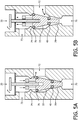
- FIGURES 5A and 5B an embodiment of a 3-way linear digital proportional piezoelectric valve in cross-section is shown in two configurations.
- a third port 73 connects with the second port 72 with fluid flow restricted by a second seat 74 and a second valve member 76.
- valve configured with a fluid opening between the second or central port 72 and the third port 73 open to fluid flow.
- the valve member 40 is configured adjacent to the seat 28 which closes the first or end port 70.
- valve configured with a fluid opening between the second port 72 and the first port 70.
- the valve member 40 is separated from the seat 28, while the second valve member 76 engages the second seat 74.
- the fluid flow to the third port 73 is closed by the second valve member 76 engaging the second seat 74.
- fluid flow entering port 72 is divided between ports 70 and 73 in proportion to the location of the valve members.
- the follower is configured with a tapered second valve element and the gripping mechanism is located between the valve member 40 and the second valve member 76.
- Other embodiments of the 3-way valve are contemplated without the well of the follower because the second valve member and second seat act to limit the position of the follower within the cavity.
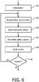
- valve initialization is performed.
- the step can include priming the valve with a predetermined number of electrical pulses.
- the step can include determining limits of the valve opening and/or closing such as with neonatal applications.
- the valve is non-magnetic and can be positioned in a magnetic field such as a MRI without adverse effect.
- the flow requirements include a direction and distance of travel of the valve element 33.
- the flow requirements are received by the microcontroller which controls the piezoelectric motor.
- the current position of the valve configured as a two way valve is closed and the flow requirements include opening the valve an amount such as x where x is expressed as a distance and direction of change in position of the follower.
- a flow requirement expressed as a volumetric amount can be converted to a distance and direction based on the valve size and physical characteristics.
- the valve element restricts the fluid flow between a first port and a second port the discrete amount proportional to the opening size which is proportional to the distance from the valve member to the valve seat.
- a pulse shape is determined in a step 84.
- the pulse shape drives the piezoelectric material to flex at a first rate with a first predetermined current intensity and flatten at a second rate with a second predetermined current intensity.
- the relationship between the current intensity and the direction of travel of the follower are described previously in reference to FIGURES 3A-3C and FIGURES 4A-4C .
- a quantity of pulses is determined in a step 86 which further restricts or opens the fluid flow through the valve a discrete amount.
- the quantity of pulses operate the piezoelectric motor to move the follower in a ratchet-like motion a discrete distance based on the received flow requirements.
- a step 88 the determined pulse shape and pulse quantity are applied to the piezoelectric material of the valve which moves the follower the discrete distance.
- the piezoelectric material is affixed to and centered on an end of a shaft.
- the follower receives the shaft and moves with the valve member.
- the follower allows the shaft to overcome friction forces and slide in response to a fast flexing or a fast flattening of the piezoelectric material.
- the shaft can include copper, aluminum, plastic, and the like.
- the gripping mechanism grips and moves with the shaft in response to a slow flexing or a slow flattening of the piezoelectric material.
- the gripping mechanism includes tin, copper, brass, rubber, plastic and the like.
- the follower restricts the fluid flow between the ports the discrete amount proportional to a distance from the valve member to the seat.
- the fluid flow is based on the linear movement of the follower operated digitally by the piezoelectric motor based on the pulse shape which determines direction and the pulse quantity which determines distance.
- the distance and direction discretely open and/or close the valve according to the received fluid requirements.
- the movement of the follower can be limited by engaging an end of the shaft opposite in the bottom of the well 38 or engaging the second seat 72 with the second valve member 76, or limiting the movement of the follower by engaging the valve seat 28 with the valve member 40. Additional electrical pulses can be applied to ensure a pressure seal of the seat and valve member.
- the time to actuate or change position is fast such as 6-8 ms.
- a change in the opening and/or closing of the valve is decided.
- the previous steps can be repeated.
- the change in position of the follower which meets the flow requirements can be determined, the pulse shape and quantity of pulses determined, and the pulses applied to fully open the valve.
- a flow monitor is disposed downstream of the valve. The controller 54 adjusts the valve opening to being the actual flow or pressure measured by the monitor into conformity with a preselected flow.
Landscapes
- Engineering & Computer Science (AREA)
- Health & Medical Sciences (AREA)
- General Engineering & Computer Science (AREA)
- Life Sciences & Earth Sciences (AREA)
- Mechanical Engineering (AREA)
- Physics & Mathematics (AREA)
- Veterinary Medicine (AREA)
- Public Health (AREA)
- Biomedical Technology (AREA)
- Heart & Thoracic Surgery (AREA)
- General Health & Medical Sciences (AREA)
- Animal Behavior & Ethology (AREA)
- Vascular Medicine (AREA)
- Cardiology (AREA)
- Emergency Medicine (AREA)
- Anesthesiology (AREA)
- Pulmonology (AREA)
- Hematology (AREA)
- Condensed Matter Physics & Semiconductors (AREA)
- General Physics & Mathematics (AREA)
- Physiology (AREA)
- Ophthalmology & Optometry (AREA)
- Biophysics (AREA)
- Pathology (AREA)
- Medical Informatics (AREA)
- Molecular Biology (AREA)
- Surgery (AREA)
- Electrically Driven Valve-Operating Means (AREA)
- Magnetic Resonance Imaging Apparatus (AREA)
Claims (15)
- Electrovanne (10), comprenant :un arbre (36) ;un moteur piézoélectrique (34) fixé à une extrémité de l'arbre (36) et entraînant l'arbre dans une première direction et dans une seconde direction opposée ;un dispositif de commande (54) qui alimente le moteur piézoélectrique (34) pour déplacer l'arbre ;un suiveur (42) qui reçoit l'arbre (36) ;un élément de vanne (40) qui se déplace avec le suiveur (42) ; etun siège de vanne (28), l'élément de vanne (40) étant configuré pour être déplacé par le suiveur (42) contre le siège de vanne (28) afin de limiter un écoulement de fluide et pour être déplacé par le suiveur (42) loin du siège de vanne afin d'augmenter l'écoulement de fluide ;caractérisée en ce que le dispositif de commande (54) est adapté pour déplacer l'arbre à une première vitesse et à une deuxième vitesse, la première vitesse étant plus rapide que la deuxième vitesse ; etle suiveur (42) est adapté pour coulisser par rapport à l'arbre en réponse à l'arbre se déplaçant à la première vitesse, et pour saisir et se déplacer avec l'arbre en réponse à l'arbre se déplaçant à la deuxième vitesse, ledit suiveur incluant l'élément de vanne (40).
- Electrovanne (10) selon la revendication 1, dans laquelle le moteur piézoélectrique (34) inclut en outre :un matériau piézoélectrique (52) qui fléchit à un premier rythme pour entraîner l'arbre (36) à la première vitesse (64) et s'aplatit à un deuxième rythme pour entraîner l'arbre (36) à la deuxième vitesse.
- Electrovanne (10) selon la revendication 2, dans laquelle le dispositif de commande (54) est connecté au matériau piézoélectrique (52) et applique les impulsions électriques pour faire fléchir et aplatir sélectivement le matériau piézoélectrique (52) à un premier rythme et à un deuxième rythme pour déplacer l'arbre aux première et deuxième vitesses.
- Electrovanne (10) selon l'une quelconque des revendications 1 à 3, dans laquelle le suiveur (42) entoure circonférentiellement l'arbre (36), et l'arbre (36) et le suiveur (42) sont configurés pour permettre à l'arbre (36) de surmonter des forces de frottement et de coulisser en réponse au mouvement relatif à la première vitesse, et pour s'attraper et se déplacer ensemble en réponse au mouvement relatif à la deuxième vitesse.
- Electrovanne (10) selon l'une quelconque des revendications 1 à 4, incluant en outre :un deuxième élément de vanne (76) connecté au suiveur.
- Electrovanne (10) selon l'une quelconque des revendications 1 à 5, incluant en outre :un boîtier (22) qui définit une cavité (24) et le siège de vanne (28) ; etdes premier et deuxième orifices de vanne (26) connectés à la cavité (24) et séparés par le siège de vanne (28) ; etdans laquelle, de préférence, le boîtier (22), le moteur piézoélectrique (34), le suiveur (42), l'élément de vanne (40) et le siège de vanne (28) sont magnétiquement inertes.
- Electrovanne (10) selon la revendication 6, incluant en outre :un deuxième élément de vanne (76) qui se déplace avec le suiveur (42) ; etdans lequel le boîtier définit en outre un troisième orifice (73) connecté à la cavité (24) et un deuxième siège de vanne (74) qui sépare le troisième orifice (73) des premier et deuxième orifices (26), le deuxième élément de vanne (76) se déplace contre le deuxième siège de vanne (72) afin de limiter l'écoulement de fluide du troisième orifice (73) et le deuxième élément de vanne (76) se déplace loin du deuxième siège de vanne afin d'augmenter l'écoulement de fluide du troisième orifice (73).
- Electrovanne (10) selon l'une quelconque des revendications 1 à 7, incluant en outre :un élément de vanne (33) connecté au suiveur (42) et à l'élément de vanne (40), l'élément de vanne (33) définissant un puits central (38) qui reçoit l'arbre (36) de telle sorte qu'un fond du puits s'engage avec une extrémité de l'arbre (36) dans une configuration entièrement ouverte ; etdans laquelle, de préférence, l'élément de vanne (33) inclut en outre un guide de nez (50) s'étendant depuis l'élément de vanne (40) qui guide l'élément de vanne (40) dans le siège (28).
- Procédé de commande de fluide, comprenant :l'application (88) d'impulsions électriques à un moteur piézoélectrique (34) qui déplace un arbre (36) fixé au moteur piézoélectrique (34) pour déplacer l'arbre (36) avec une première vitesse et une deuxième vitesse, la première vitesse étant plus rapide que la deuxième vitesse ;le déplacement de l'arbre (36) avec la première vitesse de telle sorte qu'un suiveur (42) qui reçoit l'arbre (36) coulisse par rapport à l'arbre (36) ;le déplacement de l'arbre (36) avec la deuxième vitesse de telle sorte que le suiveur (42) saisit l'arbre (36) et se déplace avec l'arbre (36) ;l'application répétée d'impulsions pour déplacer en alternance l'arbre vers un siège de vanne (28) à la deuxième vitesse et loin du siège de vanne à la première vitesse pour déplacer un élément de vanne (40) qui se déplace avec le suiveur (42) contre le siège de vanne (28) afin de limiter l'écoulement de fluide ; etl'application répétée d'impulsions pour déplacer en alternance l'arbre vers le siège de vanne à la première vitesse et loin du siège de vanne à la deuxième vitesse pour déplacer l'élément de vanne (40) qui se déplace avec le suiveur (42) loin du siège de vanne (28) afin d'augmenter l'écoulement de fluide.
- Procédé selon la revendication 9, incluant en outre :la détermination (84) d'une forme d'impulsion électrique pour le moteur piézoélectrique (34) afin d'entraîner l'arbre (36) avec la première vitesse dans une direction et une deuxième vitesse dans la direction opposée ;la détermination (86) d'une quantité d'impulsions électriques qui changent l'écoulement de fluide à travers la vanne d'une quantité discrète.
- Procédé selon l'une ou l'autre des revendications 9 et 10, dans lequel le moteur piézoélectrique (34) inclut un matériau piézoélectrique (52) et en réponse à l'application des impulsions électriques :le fléchissement du matériau piézoélectrique (52) à un premier rythme pour entraîner l'arbre avec la première vitesse, et l'aplatissement du matériau piézoélectrique (52) à un deuxième rythme pour entraîner l'arbre avec la deuxième vitesse pour déplacer le suiveur (42) vers le moteur piézoélectrique.
- Procédé selon l'une ou l'autre des revendications 9 et 10, dans lequel le moteur piézoélectrique (34) inclut un matériau piézoélectrique (52) et en réponse à l'application des impulsions électriques :le fléchissement du matériau piézoélectrique (52) à un premier rythme pour entraîner l'arbre avec la deuxième vitesse, et l'aplatissement du matériau piézoélectrique (52) à un deuxième rythme pour entraîner l'arbre avec la première vitesse pour déplacer le suiveur (42) loin du moteur piézoélectrique.
- Procédé selon l'une quelconque des revendications 9 à 12, dans lequel le suiveur (42) est connecté à un deuxième élément de vanne (76) ; et en réponse à l'application des impulsions électriques :la limitation de l'écoulement de fluide entre le premier orifice (70) et un troisième orifice (73) proportionnellement à la distance du deuxième élément de vanne (76) à un deuxième siège (74).
- Procédé selon l'une quelconque des revendications 9 à 13, dans lequel l'application (88) d'impulsions inclut en outre :l'application d'impulsions électriques supplémentaires afin de garantir un joint d'étanchéité du siège (28) et de l'élément de vanne (40) ; et/oula sélection de l'ouverture discrète de la vanne par le nombre d'impulsions électriques appliquées sur la base d'une limite d'ouverture prédéterminée.
- Procédé selon l'une quelconque des revendications 9 à 14, incluant en outre :l'amorçage (80) de la vanne avec un nombre prédéterminé d'impulsions électriques appliquées.
Applications Claiming Priority (2)
| Application Number | Priority Date | Filing Date | Title |
|---|---|---|---|
| US201361820275P | 2013-05-07 | 2013-05-07 | |
| PCT/IB2014/060934 WO2014181208A1 (fr) | 2013-05-07 | 2014-04-23 | Vanne piézoélectrique proportionnelle numérique linéaire |
Publications (2)
| Publication Number | Publication Date |
|---|---|
| EP2994672A1 EP2994672A1 (fr) | 2016-03-16 |
| EP2994672B1 true EP2994672B1 (fr) | 2017-11-22 |
Family
ID=50686001
Family Applications (1)
| Application Number | Title | Priority Date | Filing Date |
|---|---|---|---|
| EP14722780.5A Active EP2994672B1 (fr) | 2013-05-07 | 2014-04-23 | Vanne piézoélectrique proportionnelle numérique linéaire |
Country Status (7)
| Country | Link |
|---|---|
| US (1) | US9562621B2 (fr) |
| EP (1) | EP2994672B1 (fr) |
| JP (1) | JP5933148B1 (fr) |
| CN (1) | CN105190133B (fr) |
| BR (1) | BR112015027801A2 (fr) |
| RU (1) | RU2654014C2 (fr) |
| WO (1) | WO2014181208A1 (fr) |
Families Citing this family (5)
| Publication number | Priority date | Publication date | Assignee | Title |
|---|---|---|---|---|
| BR112014030877A2 (pt) * | 2012-06-13 | 2017-06-27 | Koninklijke Philips Nv | atuador de válvula para ativar acionar uma válvula compatível com ressonância magnética (rm); método de acionamento de uma válvula compatível com ressonância magnética (rm); e circuito de controle que aciona um membro de liga com memória de formato (sma) para fechar uma válvula compatível com ressonância magnética (rm) |
| CN109100777B (zh) * | 2018-10-18 | 2025-02-11 | 国家海洋局第二海洋研究所 | 变频式海洋高压空气枪震源 |
| KR102880904B1 (ko) * | 2020-09-03 | 2025-11-03 | 현대자동차주식회사 | 빛의 조사방향조절이 가능한 조명 장치 |
| JP2025500161A (ja) * | 2021-12-17 | 2025-01-09 | コーニンクレッカ フィリップス エヌ ヴェ | 非磁性医療装置で使用する熱バイメタルアクチュエータ |
| WO2023165888A1 (fr) * | 2022-03-02 | 2023-09-07 | Koninklijke Philips N.V. | Soupape piézoélectrique indépendante à double actionnement pour environnements de résonance magnétique |
Citations (1)
| Publication number | Priority date | Publication date | Assignee | Title |
|---|---|---|---|---|
| US20070120442A1 (en) * | 2004-03-02 | 2007-05-31 | Piezoelectric Technology Co., Ltd. | Small piezoelectric or electrostrictive linear motor |
Family Cites Families (17)
| Publication number | Priority date | Publication date | Assignee | Title |
|---|---|---|---|---|
| SU1167393A1 (ru) * | 1983-05-13 | 1985-07-15 | Войсковая Часть 11284 | Электромагнитный клапан с сигнализацией положени запорного органа |
| JPS6057070A (ja) * | 1983-09-05 | 1985-04-02 | Matsushita Electric Ind Co Ltd | 圧電型比例制御弁装置 |
| JPH02112669A (ja) * | 1988-10-21 | 1990-04-25 | Nippon Carbureter Co Ltd | エンジンのアイドル回転速度制御方法 |
| SU1823918A3 (ru) * | 1989-12-05 | 1993-06-23 | Mikhail E Markushin | Пьезоэлектрический клапан |
| GB9122739D0 (en) * | 1991-10-25 | 1991-12-11 | The Technology Partnership Ltd | System for controlling fluid flow |
| JPH0783344A (ja) * | 1993-09-17 | 1995-03-28 | Nissan Motor Co Ltd | 圧電型制御弁 |
| JP2001012632A (ja) * | 1999-04-30 | 2001-01-16 | Tokyo Keiso Co Ltd | 流量調節弁及び流量調節システム |
| US6684904B2 (en) | 1999-06-15 | 2004-02-03 | Seiko Instruments Inc. | Variable pressure valve apparatus |
| US6739575B2 (en) | 2002-06-06 | 2004-05-25 | Caterpillar Inc | Piezoelectric valve system |
| US20040003786A1 (en) * | 2002-06-18 | 2004-01-08 | Gatecliff George W. | Piezoelectric valve actuation |
| DE10359675B3 (de) | 2003-12-18 | 2005-07-07 | Volkswagen Mechatronic Gmbh & Co. Kg | Verfahren und Vorrichtung zum Steuern eines Ventils und Verfahren und Vorrichtung zum Steuern einer Pumpe-Düse-Vorrichtung mit dem Ventil |
| KR100443638B1 (ko) * | 2004-03-02 | 2004-08-11 | (주)피에조테크놀리지 | 소형 압전/전왜 초음파 리니어모터 |
| CN101021279A (zh) * | 2007-02-14 | 2007-08-22 | 律天龙 | 三通导流阀 |
| RU66791U1 (ru) * | 2007-05-22 | 2007-09-27 | Общество с ограниченной ответственностью "Национальная инновационная компания "Новые энергетические проекты" | Малогабаритный пьезоэлектрический клапан для систем автоматики |
| US8191857B2 (en) | 2008-10-09 | 2012-06-05 | Parker-Hannifin Corporation | Linear motor valve |
| US8777179B2 (en) * | 2008-11-24 | 2014-07-15 | Hess Innovation Gmbh | Drive mechanism for the movement of an object along an axis of motion and micro-valve |
| CN101776159A (zh) * | 2009-01-14 | 2010-07-14 | 胡玉成 | 小功率压电陶瓷换向阀 |
-
2014
- 2014-04-23 EP EP14722780.5A patent/EP2994672B1/fr active Active
- 2014-04-23 CN CN201480025706.1A patent/CN105190133B/zh active Active
- 2014-04-23 BR BR112015027801A patent/BR112015027801A2/pt not_active Application Discontinuation
- 2014-04-23 WO PCT/IB2014/060934 patent/WO2014181208A1/fr not_active Ceased
- 2014-04-23 RU RU2015152026A patent/RU2654014C2/ru not_active IP Right Cessation
- 2014-04-23 JP JP2016508282A patent/JP5933148B1/ja active Active
- 2014-04-23 US US14/888,718 patent/US9562621B2/en active Active
Patent Citations (1)
| Publication number | Priority date | Publication date | Assignee | Title |
|---|---|---|---|---|
| US20070120442A1 (en) * | 2004-03-02 | 2007-05-31 | Piezoelectric Technology Co., Ltd. | Small piezoelectric or electrostrictive linear motor |
Also Published As
| Publication number | Publication date |
|---|---|
| RU2015152026A (ru) | 2017-06-15 |
| EP2994672A1 (fr) | 2016-03-16 |
| RU2015152026A3 (fr) | 2018-03-06 |
| WO2014181208A1 (fr) | 2014-11-13 |
| CN105190133A (zh) | 2015-12-23 |
| CN105190133B (zh) | 2019-06-04 |
| US9562621B2 (en) | 2017-02-07 |
| BR112015027801A2 (pt) | 2017-07-25 |
| JP2016518193A (ja) | 2016-06-23 |
| RU2654014C2 (ru) | 2018-05-15 |
| US20160053909A1 (en) | 2016-02-25 |
| JP5933148B1 (ja) | 2016-06-08 |
Similar Documents
| Publication | Publication Date | Title |
|---|---|---|
| US9562621B2 (en) | Linear digital proportional piezoelectric valve | |
| JP4196293B2 (ja) | 真空調圧用バルブ | |
| KR102210582B1 (ko) | 밸브장치, 유량 조정방법, 유체 제어장치, 유량 제어방법, 반도체 제조장치 및 반도체 제조방법 | |
| CN103124873B (zh) | 控制阀 | |
| CN104514904B (zh) | 流体驱动式截止阀 | |
| KR20190045866A (ko) | 래칭 공압식 제어 밸브 | |
| KR102304548B1 (ko) | 밸브장치 및 그 제어장치를 사용한 제어방법, 유체 제어장치 및 반도체 제조장치 | |
| WO2019217788A1 (fr) | Appareil et procédé de régulation de débit d'élément multivanne | |
| CN104565504A (zh) | 气动阀门控制机构 | |
| CN103055401A (zh) | 呼吸机及比例阀 | |
| US20050092952A1 (en) | Proportional poppet valve | |
| JP2006153141A (ja) | エントランスチャンネル付微小流量制御装置。 | |
| KR101107612B1 (ko) | 포지셔너용 토크모터 장치 | |
| WO2009149137A1 (fr) | Vanne à manchon déformable à actionnement piézoélectrique | |
| JP5675777B2 (ja) | 流体作動機器用の面シーリング環状バルブ | |
| JP4116269B2 (ja) | 人工呼吸器用呼気弁装置および人工呼吸器 | |
| US20090180905A1 (en) | Pump element and pump having such a pump element | |
| EP3289259B1 (fr) | Clapet proportionnel à solénoïde miniature à profil bas | |
| CN111486073A (zh) | 电磁泵 | |
| US20190346057A1 (en) | High flow miniature proportional control valve with linear moving magnetic voice coil motor | |
| EP1643515A2 (fr) | Unité de commande pour une électrovanne | |
| US20170211717A1 (en) | Magnetic metering valve and method of operating the same | |
| CN204459386U (zh) | 气动阀门控制机构 | |
| CN103429910A (zh) | 阀 | |
| WO2015198000A1 (fr) | Ventilateurs |
Legal Events
| Date | Code | Title | Description |
|---|---|---|---|
| PUAI | Public reference made under article 153(3) epc to a published international application that has entered the european phase |
Free format text: ORIGINAL CODE: 0009012 |
|
| 17P | Request for examination filed |
Effective date: 20151207 |
|
| AK | Designated contracting states |
Kind code of ref document: A1 Designated state(s): AL AT BE BG CH CY CZ DE DK EE ES FI FR GB GR HR HU IE IS IT LI LT LU LV MC MK MT NL NO PL PT RO RS SE SI SK SM TR |
|
| AX | Request for extension of the european patent |
Extension state: BA ME |
|
| DAX | Request for extension of the european patent (deleted) | ||
| 17Q | First examination report despatched |
Effective date: 20161122 |
|
| GRAP | Despatch of communication of intention to grant a patent |
Free format text: ORIGINAL CODE: EPIDOSNIGR1 |
|
| INTG | Intention to grant announced |
Effective date: 20170613 |
|
| GRAS | Grant fee paid |
Free format text: ORIGINAL CODE: EPIDOSNIGR3 |
|
| GRAA | (expected) grant |
Free format text: ORIGINAL CODE: 0009210 |
|
| AK | Designated contracting states |
Kind code of ref document: B1 Designated state(s): AL AT BE BG CH CY CZ DE DK EE ES FI FR GB GR HR HU IE IS IT LI LT LU LV MC MK MT NL NO PL PT RO RS SE SI SK SM TR |
|
| REG | Reference to a national code |
Ref country code: GB Ref legal event code: FG4D |
|
| REG | Reference to a national code |
Ref country code: CH Ref legal event code: EP |
|
| REG | Reference to a national code |
Ref country code: IE Ref legal event code: FG4D |
|
| REG | Reference to a national code |
Ref country code: AT Ref legal event code: REF Ref document number: 948727 Country of ref document: AT Kind code of ref document: T Effective date: 20171215 |
|
| REG | Reference to a national code |
Ref country code: DE Ref legal event code: R096 Ref document number: 602014017559 Country of ref document: DE |
|
| REG | Reference to a national code |
Ref country code: NL Ref legal event code: MP Effective date: 20171122 |
|
| REG | Reference to a national code |
Ref country code: LT Ref legal event code: MG4D |
|
| REG | Reference to a national code |
Ref country code: AT Ref legal event code: MK05 Ref document number: 948727 Country of ref document: AT Kind code of ref document: T Effective date: 20171122 |
|
| REG | Reference to a national code |
Ref country code: FR Ref legal event code: PLFP Year of fee payment: 5 |
|
| PG25 | Lapsed in a contracting state [announced via postgrant information from national office to epo] |
Ref country code: NL Free format text: LAPSE BECAUSE OF FAILURE TO SUBMIT A TRANSLATION OF THE DESCRIPTION OR TO PAY THE FEE WITHIN THE PRESCRIBED TIME-LIMIT Effective date: 20171122 Ref country code: ES Free format text: LAPSE BECAUSE OF FAILURE TO SUBMIT A TRANSLATION OF THE DESCRIPTION OR TO PAY THE FEE WITHIN THE PRESCRIBED TIME-LIMIT Effective date: 20171122 Ref country code: LT Free format text: LAPSE BECAUSE OF FAILURE TO SUBMIT A TRANSLATION OF THE DESCRIPTION OR TO PAY THE FEE WITHIN THE PRESCRIBED TIME-LIMIT Effective date: 20171122 Ref country code: SE Free format text: LAPSE BECAUSE OF FAILURE TO SUBMIT A TRANSLATION OF THE DESCRIPTION OR TO PAY THE FEE WITHIN THE PRESCRIBED TIME-LIMIT Effective date: 20171122 Ref country code: FI Free format text: LAPSE BECAUSE OF FAILURE TO SUBMIT A TRANSLATION OF THE DESCRIPTION OR TO PAY THE FEE WITHIN THE PRESCRIBED TIME-LIMIT Effective date: 20171122 Ref country code: NO Free format text: LAPSE BECAUSE OF FAILURE TO SUBMIT A TRANSLATION OF THE DESCRIPTION OR TO PAY THE FEE WITHIN THE PRESCRIBED TIME-LIMIT Effective date: 20180222 |
|
| PG25 | Lapsed in a contracting state [announced via postgrant information from national office to epo] |
Ref country code: BG Free format text: LAPSE BECAUSE OF FAILURE TO SUBMIT A TRANSLATION OF THE DESCRIPTION OR TO PAY THE FEE WITHIN THE PRESCRIBED TIME-LIMIT Effective date: 20180222 Ref country code: AT Free format text: LAPSE BECAUSE OF FAILURE TO SUBMIT A TRANSLATION OF THE DESCRIPTION OR TO PAY THE FEE WITHIN THE PRESCRIBED TIME-LIMIT Effective date: 20171122 Ref country code: GR Free format text: LAPSE BECAUSE OF FAILURE TO SUBMIT A TRANSLATION OF THE DESCRIPTION OR TO PAY THE FEE WITHIN THE PRESCRIBED TIME-LIMIT Effective date: 20180223 Ref country code: RS Free format text: LAPSE BECAUSE OF FAILURE TO SUBMIT A TRANSLATION OF THE DESCRIPTION OR TO PAY THE FEE WITHIN THE PRESCRIBED TIME-LIMIT Effective date: 20171122 Ref country code: LV Free format text: LAPSE BECAUSE OF FAILURE TO SUBMIT A TRANSLATION OF THE DESCRIPTION OR TO PAY THE FEE WITHIN THE PRESCRIBED TIME-LIMIT Effective date: 20171122 Ref country code: HR Free format text: LAPSE BECAUSE OF FAILURE TO SUBMIT A TRANSLATION OF THE DESCRIPTION OR TO PAY THE FEE WITHIN THE PRESCRIBED TIME-LIMIT Effective date: 20171122 |
|
| PG25 | Lapsed in a contracting state [announced via postgrant information from national office to epo] |
Ref country code: CY Free format text: LAPSE BECAUSE OF FAILURE TO SUBMIT A TRANSLATION OF THE DESCRIPTION OR TO PAY THE FEE WITHIN THE PRESCRIBED TIME-LIMIT Effective date: 20171122 Ref country code: EE Free format text: LAPSE BECAUSE OF FAILURE TO SUBMIT A TRANSLATION OF THE DESCRIPTION OR TO PAY THE FEE WITHIN THE PRESCRIBED TIME-LIMIT Effective date: 20171122 Ref country code: SK Free format text: LAPSE BECAUSE OF FAILURE TO SUBMIT A TRANSLATION OF THE DESCRIPTION OR TO PAY THE FEE WITHIN THE PRESCRIBED TIME-LIMIT Effective date: 20171122 Ref country code: CZ Free format text: LAPSE BECAUSE OF FAILURE TO SUBMIT A TRANSLATION OF THE DESCRIPTION OR TO PAY THE FEE WITHIN THE PRESCRIBED TIME-LIMIT Effective date: 20171122 Ref country code: DK Free format text: LAPSE BECAUSE OF FAILURE TO SUBMIT A TRANSLATION OF THE DESCRIPTION OR TO PAY THE FEE WITHIN THE PRESCRIBED TIME-LIMIT Effective date: 20171122 |
|
| REG | Reference to a national code |
Ref country code: DE Ref legal event code: R097 Ref document number: 602014017559 Country of ref document: DE |
|
| PG25 | Lapsed in a contracting state [announced via postgrant information from national office to epo] |
Ref country code: PL Free format text: LAPSE BECAUSE OF FAILURE TO SUBMIT A TRANSLATION OF THE DESCRIPTION OR TO PAY THE FEE WITHIN THE PRESCRIBED TIME-LIMIT Effective date: 20171122 Ref country code: RO Free format text: LAPSE BECAUSE OF FAILURE TO SUBMIT A TRANSLATION OF THE DESCRIPTION OR TO PAY THE FEE WITHIN THE PRESCRIBED TIME-LIMIT Effective date: 20171122 Ref country code: SM Free format text: LAPSE BECAUSE OF FAILURE TO SUBMIT A TRANSLATION OF THE DESCRIPTION OR TO PAY THE FEE WITHIN THE PRESCRIBED TIME-LIMIT Effective date: 20171122 Ref country code: IT Free format text: LAPSE BECAUSE OF FAILURE TO SUBMIT A TRANSLATION OF THE DESCRIPTION OR TO PAY THE FEE WITHIN THE PRESCRIBED TIME-LIMIT Effective date: 20171122 |
|
| PLBE | No opposition filed within time limit |
Free format text: ORIGINAL CODE: 0009261 |
|
| STAA | Information on the status of an ep patent application or granted ep patent |
Free format text: STATUS: NO OPPOSITION FILED WITHIN TIME LIMIT |
|
| 26N | No opposition filed |
Effective date: 20180823 |
|
| PG25 | Lapsed in a contracting state [announced via postgrant information from national office to epo] |
Ref country code: SI Free format text: LAPSE BECAUSE OF FAILURE TO SUBMIT A TRANSLATION OF THE DESCRIPTION OR TO PAY THE FEE WITHIN THE PRESCRIBED TIME-LIMIT Effective date: 20171122 Ref country code: MC Free format text: LAPSE BECAUSE OF FAILURE TO SUBMIT A TRANSLATION OF THE DESCRIPTION OR TO PAY THE FEE WITHIN THE PRESCRIBED TIME-LIMIT Effective date: 20171122 |
|
| REG | Reference to a national code |
Ref country code: CH Ref legal event code: PL |
|
| REG | Reference to a national code |
Ref country code: BE Ref legal event code: MM Effective date: 20180430 |
|
| REG | Reference to a national code |
Ref country code: IE Ref legal event code: MM4A |
|
| PG25 | Lapsed in a contracting state [announced via postgrant information from national office to epo] |
Ref country code: LU Free format text: LAPSE BECAUSE OF NON-PAYMENT OF DUE FEES Effective date: 20180423 |
|
| PG25 | Lapsed in a contracting state [announced via postgrant information from national office to epo] |
Ref country code: BE Free format text: LAPSE BECAUSE OF NON-PAYMENT OF DUE FEES Effective date: 20180430 Ref country code: CH Free format text: LAPSE BECAUSE OF NON-PAYMENT OF DUE FEES Effective date: 20180430 Ref country code: LI Free format text: LAPSE BECAUSE OF NON-PAYMENT OF DUE FEES Effective date: 20180430 |
|
| PG25 | Lapsed in a contracting state [announced via postgrant information from national office to epo] |
Ref country code: IE Free format text: LAPSE BECAUSE OF NON-PAYMENT OF DUE FEES Effective date: 20180423 |
|
| PG25 | Lapsed in a contracting state [announced via postgrant information from national office to epo] |
Ref country code: MT Free format text: LAPSE BECAUSE OF NON-PAYMENT OF DUE FEES Effective date: 20180423 |
|
| PG25 | Lapsed in a contracting state [announced via postgrant information from national office to epo] |
Ref country code: TR Free format text: LAPSE BECAUSE OF FAILURE TO SUBMIT A TRANSLATION OF THE DESCRIPTION OR TO PAY THE FEE WITHIN THE PRESCRIBED TIME-LIMIT Effective date: 20171122 |
|
| PG25 | Lapsed in a contracting state [announced via postgrant information from national office to epo] |
Ref country code: PT Free format text: LAPSE BECAUSE OF FAILURE TO SUBMIT A TRANSLATION OF THE DESCRIPTION OR TO PAY THE FEE WITHIN THE PRESCRIBED TIME-LIMIT Effective date: 20171122 |
|
| PG25 | Lapsed in a contracting state [announced via postgrant information from national office to epo] |
Ref country code: HU Free format text: LAPSE BECAUSE OF FAILURE TO SUBMIT A TRANSLATION OF THE DESCRIPTION OR TO PAY THE FEE WITHIN THE PRESCRIBED TIME-LIMIT; INVALID AB INITIO Effective date: 20140423 Ref country code: MK Free format text: LAPSE BECAUSE OF NON-PAYMENT OF DUE FEES Effective date: 20171122 |
|
| PG25 | Lapsed in a contracting state [announced via postgrant information from national office to epo] |
Ref country code: AL Free format text: LAPSE BECAUSE OF FAILURE TO SUBMIT A TRANSLATION OF THE DESCRIPTION OR TO PAY THE FEE WITHIN THE PRESCRIBED TIME-LIMIT Effective date: 20171122 Ref country code: IS Free format text: LAPSE BECAUSE OF FAILURE TO SUBMIT A TRANSLATION OF THE DESCRIPTION OR TO PAY THE FEE WITHIN THE PRESCRIBED TIME-LIMIT Effective date: 20180322 |
|
| REG | Reference to a national code |
Ref country code: DE Ref legal event code: R084 Ref document number: 602014017559 Country of ref document: DE |
|
| REG | Reference to a national code |
Ref country code: GB Ref legal event code: 746 Effective date: 20241216 |
|
| PGFP | Annual fee paid to national office [announced via postgrant information from national office to epo] |
Ref country code: GB Payment date: 20260421 Year of fee payment: 13 |
|
| PGFP | Annual fee paid to national office [announced via postgrant information from national office to epo] |
Ref country code: DE Payment date: 20260421 Year of fee payment: 13 |
|
| PGFP | Annual fee paid to national office [announced via postgrant information from national office to epo] |
Ref country code: FR Payment date: 20260423 Year of fee payment: 13 |