EP2995004B1 - Differential sampling circuit with harmonic cancellation - Google Patents
Differential sampling circuit with harmonic cancellation Download PDFInfo
- Publication number
- EP2995004B1 EP2995004B1 EP14794510.9A EP14794510A EP2995004B1 EP 2995004 B1 EP2995004 B1 EP 2995004B1 EP 14794510 A EP14794510 A EP 14794510A EP 2995004 B1 EP2995004 B1 EP 2995004B1
- Authority
- EP
- European Patent Office
- Prior art keywords
- coupled
- field effect
- effect transistor
- drain
- source
- Prior art date
- Legal status (The legal status is an assumption and is not a legal conclusion. Google has not performed a legal analysis and makes no representation as to the accuracy of the status listed.)
- Active
Links
Images

Classifications
-
- G—PHYSICS
- G11—INFORMATION STORAGE
- G11C—STATIC STORES
- G11C27/00—Electric analogue stores, e.g. for storing instantaneous values
- G11C27/02—Sample-and-hold arrangements
-
- H—ELECTRICITY
- H03—ELECTRONIC CIRCUITRY
- H03M—CODING; DECODING; CODE CONVERSION IN GENERAL
- H03M1/00—Analogue/digital conversion; Digital/analogue conversion
- H03M1/12—Analogue/digital converters
- H03M1/124—Sampling or signal conditioning arrangements specially adapted for A/D converters
- H03M1/1245—Details of sampling arrangements or methods
Definitions
- This relates generally to electronic circuitry, and more particularly to a differential sampling circuit with harmonic cancellation.
- An analog-to-digital converter is used to generate a sequence of digital codes representing the strength of an input signal at corresponding points in time.
- An ADC may be implemented in various well-known forms, such as successive approximation (SAR) ADC, pipelined ADC, etc.
- SFDR Spurious-Free Dynamic Range
- SFDR is referred to as the ratio of the RMS (root mean squared) amplitude of the carrier frequency (maximum signal component or fundamental frequency) to the RMS value of the next largest noise or harmonic distortion component (component having a frequency an integer number of times the carrier frequency).
- SFDR may be measured in dBc (decibels with respect to the carrier frequency amplitude) or in dBFS (decibels with respect to the ADC's full-scale range). Using this definition, SFDR should ideally have an infinite value.
- a sample and hold circuit at the input of an ADC may cause the generation of harmonic components because of the inherent non-linearity of the MOS sampling switches, junction diodes, and sampling glitches.
- the second harmonic HD2 and the third harmonic HD3 are often the dominant components affecting the SFDR at high input frequencies.
- the present invention provides a differential sampling circuit according to the appended claim 1 and a method for cancelling the second harmonic in a differential sampling circuit according to the appended claim 9.
- a described example includes a compensation circuit for reducing or eliminating second harmonic content resulting from a phase imbalance in a differential sampling circuit due to the differential switch.
- the input imbalance in a differential circuit is caused by several factors such as board mismatch, driving transformer mismatch, etc.
- the compensation circuit provides field effect transistors operating in a saturation mode coupled in parallel with the differential switch of the sampling circuit, which operates in a linear mode. By placing a saturation region transistor across the differential switch, the harmonic content does not flow through the sampling capacitors of the sampling circuit, but instead, flows through the compensation circuit.
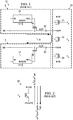
- FIG. 1 illustrates a typical embodiment of a known sampling circuit 10 for differential inputs INP and INM, as used, for example, in the front end of an analog-to-digital converter (ADC).
- FIG. 1 is a simplified representation and intended to be illustrative only. Additional circuitry will be required to implement a specific ADC or other application. For example, an RCR filter (not shown) is commonly used to shunt the two inputs INP and INM in order to set the analog bandwidth of the sampling circuit 10; an RLC network (not shown) may be used to represent package parasitics; and one or more amplifiers and/or other processing and logic circuitry will follow the sampling circuit to store and further process the signals being sampled.
- an RCR filter (not shown) is commonly used to shunt the two inputs INP and INM in order to set the analog bandwidth of the sampling circuit 10
- an RLC network (not shown) may be used to represent package parasitics
- one or more amplifiers and/or other processing and logic circuitry will follow the sampling circuit
- a pair of input stages 2 and 3 feed input signals INP and INM to a pass-through network 20, where the signals will be passed on to the rest of the ADC circuit (not shown).
- sampling capacitors 12 and 13 are coupled in series with corresponding sampling switches 14 and 15 to receive and temporarily store differential inputs INP and INM.
- the sampling switches 14, 15 (as well as other switches described herein) are implemented with field-effect transistors, as shown in the figures, with sizes chosen such that the bandwidth of the circuit is much greater than the highest input frequency of interest.
- the gates of the sampling switches 14, 15 are driven by boost circuits 16 and 17, respectively.
- Each of the boost circuits 16, 17 takes its respective input signal (INP or INM) and generates an output signal equal to the input level shifted by V C (shown as IN+ V C in the BOOST circuits), where V C is a constant voltage, when the clock signal CLK is high.
- V C is a constant voltage
- each of the boost circuits 16, 17 generates a zero or low level output.
- the sampling switches 14, 15 see signal independent gate to source voltage (shown as V C in FIG. 1 ) and therefore signal independent switch resistance while transmitting the input signals.
- the pair of nodes INCM are driven by a voltage source (not shown) having a value defined by the circuit following this sampling stage, e.g., typically an amplifier circuit, and the voltage INCM is passed into the circuit by two single-ended switches 21 and 23.
- a voltage source not shown
- the voltage INCM is passed into the circuit by two single-ended switches 21 and 23.
- FIG. 2 illustrates how the second harmonic content is generated due to phase imbalance.
- the current through switch 22 operating in its linear region is given by the following equations:
- I HD 2 K v 2 / 2 sin 2 ⁇ t + ⁇ ⁇ K v 2 / 2 sin 2 ⁇ t , where the current I HD2 flows from drain (node TOPP) to source (node TOPM) of transistor 22.
- I HD2 is proportional to Kv 2 , where K is proportional to W and v is proportional to 1/W. Therefore, I HD2 is proportional to 1/W.
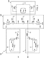
- the pass-through network 120 is basically the same as network 20, with differential transistor 122 operating in a linear region and bounded on either end by the single ended switches 121 and 123.
- the drain of single ended switch 121 is coupled to current source IINP, which is coupled to voltage AVDD, while the drain of single ended switch 123 is coupled to current source IINM, which is also coupled to voltage AVDD.
- a compensation network 140 is added in parallel with the pass-through network 120. More specifically, the compensation network 140 adds two compensation transistors 142 and 143 each having the same width W and length L as the differential transistor 122.
- Current sources 131 and 133 are DC current sources sufficiently sized to operate the compensation transistors 142, 143 in a saturation region under the swing across the differential switch 122.
- the expression for the harmonic current I HD2 described above has two components, namely, K(v 2 /2)sin 2 ( ⁇ t+ ⁇ ) and K(v 2 /2)sin 2 ( ⁇ t). These two harmonic components can be cancelled by the parallel compensation network 140 shown in FIG. 3 .
- the single-ended transistors 121, 123 acts like switches in the current path, and in the discrete time domain, the current can be switched off using the single-ended transistors.
- I DS K / 2 VGS ⁇ V T 2 .
- I DS 142 K / 2 V INCM + vSin ⁇ t ⁇ V T 2 .
- I HD2 142 K(v 2 /2)sin 2 ( ⁇ t), which flows from the node TOPP to ground.
- I DS 143 K / 2 V INCM ⁇ vSin ⁇ t + ⁇ ⁇ V T 2 .
- I HD2 143 K(v 2 /2)sin 2 ( ⁇ t+ ⁇ ), which flows from the node TOPM to ground.
- PSP physical surface potential
- Table I shows the transistor sizes and values of the sampling capacitors and current sources, as used in a circuit simulation for the circuit shown in FIG. 3 : TABLE I Element Size Transistor 14 206 ⁇ m W x 0.25 ⁇ m L Transistor 15 206 ⁇ m W x 0.25 ⁇ m L Transistor 121 8.4 ⁇ m W x 0.21 ⁇ m L Transistor 123 8.4 ⁇ m W x 0.21 ⁇ m L Transistor 122 151 ⁇ m W x 0.21 ⁇ m L Transistor 142 151 ⁇ m W x 0.21 ⁇ m L Transistor 143 151 ⁇ m W x 0.21 ⁇ m L Capacitor 12 2 pF Capacitor 13 2 pF Current source 131 1.8 mA Current source 133 1.8 Ma
- FIG. 4 illustrates a complete discrete time domain version of sampling circuit 200.
- the pass-through network 220 is basically the same as network 120, except that the gates of differential transistor 222 and single ended switches 221 and 223 are driven with a clock pulse CLKP rather than voltage V g .
- MOS switches 244 and 245 are added at the drain side of compensation transistors 242 and 243, respectively, and are used to switch off the compensation transistors.
- the MOS switches 244, 245 can be small in size because the current drawn by the compensation transistors 242, 243 depends on V GS .
- a small second order effect is present due to the finite g ds associated with the compensation transistors. Since the differential switch 222, the single-ended switches 221, 223, and the MOS switches 244, 245, all see the same bias voltage, the switching off condition is the same as in FIG. 1 .
Landscapes
- Engineering & Computer Science (AREA)
- Theoretical Computer Science (AREA)
- Amplifiers (AREA)
- Electronic Switches (AREA)
- Analogue/Digital Conversion (AREA)
Description
- This relates generally to electronic circuitry, and more particularly to a differential sampling circuit with harmonic cancellation.
- An analog-to-digital converter (ADC) is used to generate a sequence of digital codes representing the strength of an input signal at corresponding points in time. An ADC may be implemented in various well-known forms, such as successive approximation (SAR) ADC, pipelined ADC, etc.
- The term "Spurious-Free Dynamic Range" (SFDR) of an ADC generally quantifies the extent to which harmonic content is present in the output of the ADC. Ideally, harmonic content should be absent in the ADC output. According to one convention, SFDR is referred to as the ratio of the RMS (root mean squared) amplitude of the carrier frequency (maximum signal component or fundamental frequency) to the RMS value of the next largest noise or harmonic distortion component (component having a frequency an integer number of times the carrier frequency). SFDR may be measured in dBc (decibels with respect to the carrier frequency amplitude) or in dBFS (decibels with respect to the ADC's full-scale range). Using this definition, SFDR should ideally have an infinite value.
- Several factors may contribute to a low SFDR in an ADC. For example, a sample and hold circuit at the input of an ADC may cause the generation of harmonic components because of the inherent non-linearity of the MOS sampling switches, junction diodes, and sampling glitches. The second harmonic HD2 and the third harmonic HD3 are often the dominant components affecting the SFDR at high input frequencies.
- Document
US5963156 discloses a differential sample and hold circuit with common mode differential signal feedback. - Document
US6653976 discloses a fully differential sampling circuit which reduces a sampling error to suppress the occurrence of a second harmonic component by arranging the sampling capacitors in opposing relationship with respect to connecting direction. - The present invention provides a differential sampling circuit according to the appended claim 1 and a method for cancelling the second harmonic in a differential sampling circuit according to the appended claim 9.
-
-
FIG. 1 is a schematic diagram illustrating the front end of a conventional sampling circuit for an analog-to-digital converter. -
FIG. 2 is a portion of the schematic diagram ofFIG. 1 illustrating the generation of harmonic content in the differential switch due to phase imbalance. -
FIG. 3 is a schematic diagram illustrating a sampling circuit having compensation for harmonic content generated in the differential switch. -
FIG. 4 is a schematic diagram illustrating a discrete alternative sampling circuit with compensation for harmonic content. - A described example includes a compensation circuit for reducing or eliminating second harmonic content resulting from a phase imbalance in a differential sampling circuit due to the differential switch. The input imbalance in a differential circuit is caused by several factors such as board mismatch, driving transformer mismatch, etc. The compensation circuit provides field effect transistors operating in a saturation mode coupled in parallel with the differential switch of the sampling circuit, which operates in a linear mode. By placing a saturation region transistor across the differential switch, the harmonic content does not flow through the sampling capacitors of the sampling circuit, but instead, flows through the compensation circuit.
-
FIG. 1 illustrates a typical embodiment of a knownsampling circuit 10 for differential inputs INP and INM, as used, for example, in the front end of an analog-to-digital converter (ADC).FIG. 1 is a simplified representation and intended to be illustrative only. Additional circuitry will be required to implement a specific ADC or other application. For example, an RCR filter (not shown) is commonly used to shunt the two inputs INP and INM in order to set the analog bandwidth of thesampling circuit 10; an RLC network (not shown) may be used to represent package parasitics; and one or more amplifiers and/or other processing and logic circuitry will follow the sampling circuit to store and further process the signals being sampled. - A pair of
input stages network 20, where the signals will be passed on to the rest of the ADC circuit (not shown). In theinput stages sampling capacitors corresponding sampling switches sampling switches boost circuits boost circuits boost circuits FIG. 1 ) and therefore signal independent switch resistance while transmitting the input signals. - In the pass-through
network 20, the pair of nodes INCM are driven by a voltage source (not shown) having a value defined by the circuit following this sampling stage, e.g., typically an amplifier circuit, and the voltage INCM is passed into the circuit by two single-ended switches - Ideally in a differential sampling circuit, even harmonics are not present. However, if the phase difference between differential inputs INP and INM is different from 180 degrees, i.e., when there is a phase imbalance, and the
differential closing switch 22 generates a second harmonic current IHD2 as indicated inFIG. 1 . The current IHD2 representing harmonic content multiplied by the capacitor impedance creates a voltage drop across thesampling capacitors ended switches differential switch 22 for the same length. Thus, the contribution of harmonic content HD2 due to thedifferential switch 22 dominates since the HD2 current is proportional to width for a particular voltage swing across the transistor. However, as described below, the non-linearity associated with thedifferential switch 22 operating in its linear region can be cancelled by adding a similar transistor in parallel operating in its saturation region. -
FIG. 2 illustrates how the second harmonic content is generated due to phase imbalance. The current throughswitch 22 operating in its linear region is given by the following equations: - IDS = (K/2)((VGS - VT)VDS - VDS 2/2), where K=µnCOX(W/L) and Φ is the phase imbalance due to input phase imbalance (COX is the gate oxide capacitance per area);
- VGS = Vg + vSin(ωt+Φ) - VINCM, where VINCM is the DC operating point at the drain and source of
transistor 22, and Vg is a constant voltage sufficient to keeptransistor 22 in deep inversion;


- Substituting for VGS and VDS and solving for the second harmonic term yields:

transistor 22. As expected, Φ = 0, therefore IHD2 = 0. From these equations, IHD2 is proportional to Kv2, where K is proportional to W and v is proportional to 1/W. Therefore, IHD2 is proportional to 1/W. - This means that in order to reduce the harmonic current IHD2, the width W of
transistor 22 has to be increased. However, increasing the width W oftransistor 22 also increases parasitics at the nodes TOPP and TOPM, and this makes the specification for the subsequent amplifier circuit much tighter. However, a cancellation method will now be described, which has the advantage of less parasitic capacitance at the nodes TOPP and TOPM, with a theoretically complete cancellation of harmonic content. - In the
sampling circuit 100 ofFIG. 3 , the pass-throughnetwork 120 is basically the same asnetwork 20, withdifferential transistor 122 operating in a linear region and bounded on either end by the single endedswitches ended switch 121 is coupled to current source IINP, which is coupled to voltage AVDD, while the drain of singleended switch 123 is coupled to current source IINM, which is also coupled to voltage AVDD. Acompensation network 140 is added in parallel with the pass-throughnetwork 120. More specifically, thecompensation network 140 adds twocompensation transistors differential transistor 122.Current sources compensation transistors differential switch 122. - The expression for the harmonic current IHD2 described above has two components, namely, K(v2/2)sin2(ωt+Φ) and K(v2/2)sin2(ωt). These two harmonic components can be cancelled by the
parallel compensation network 140 shown inFIG. 3 . The single-ended transistors - In general, the current through a transistor in saturation region is given by:

ended transistor 142 is given by:
IHD2 142 = K(v2/2)sin2(ωt), which flows from the node TOPP to ground.
Similarly, current through the single-endedtransistor 143 is given by:
IHD2 143 = K(v2/2)sin2(ωt+Φ), which flows from the node TOPM to ground.
Thus, the total harmonic current IHD2' flowing from node TOPM to node TOPP is:
- Using this solution, the harmonic current IHD2 circulates within the
compensation circuit 140 andtransistor 122, as shown inFIG. 3 , and does not flow to the input or create HD2 voltage. Since the swing across thedifferential switch transistor 122 is very small, the amount of third harmonic current HD3 generated at the differential switch is negligible using this solution. In fact, this solution reduces the third harmonic current HD3 generated bytransistor 122 as the compensation circuit linearizes the impedance oftransistor 122. The performance of this circuit has been verified using the PSP (physical surface potential) model to simulate all transistors, since the PSP model best defines the linearity associated with a switch around VDS=0. - For example, Table I below shows the transistor sizes and values of the sampling capacitors and current sources, as used in a circuit simulation for the circuit shown in
FIG. 3 :TABLE I Element Size Transistor 14 206 µm W x 0.25 µm L Transistor 15 206 µm W x 0.25 µm L Transistor 121 8.4 µm W x 0.21 µm L Transistor 123 8.4 µm W x 0.21 µm L Transistor 122 151 µm W x 0.21 µm L Transistor 142 151 µm W x 0.21 µm L Transistor 143 151 µm W x 0.21 µm L Capacitor 12 2 pF Capacitor 13 2 pF Current source 1311.8 mA Current source 1331.8 Ma - In order to exclude non-linearity associated with source/drain junction capacitors of
sampling transistors boost circuits -
FIG. 4 illustrates a complete discrete time domain version ofsampling circuit 200. Insampling circuit 200, the pass-throughnetwork 220 is basically the same asnetwork 120, except that the gates ofdifferential transistor 222 and single ended switches 221 and 223 are driven with a clock pulse CLKP rather than voltage Vg. - Two MOS switches 244 and 245 are added at the drain side of
compensation transistors compensation transistors differential switch 222, the single-endedswitches FIG. 1 . - Modifications are possible in the described embodiments, and other embodiments are possible, within the scope of the claims.
Claims (11)
- A differential sampling circuit, comprising:a pair of input stages (2,3) comprising a first and a second input stage, each having a sampling switch (14,15) coupled to a differential input signal and a sampling capacitor (12,13) having an input coupled in series with the sampling switch and an output;a pass-through network (120,220) shunting the input stages between the outputs of the sampling capacitors, the pass-through network comprising a plurality of field effect transistors (121,122,123,221,222,223) operating in a linear region; anda cancellation network (140,240) coupled in parallel with the pass-through network, the cancellation network comprising a plurality of field effect transistors (142,143,242,243,244,245) operating in a saturation region, and wherein the pass-through network comprises:a first current source (131,133,231,233) coupled to a first voltage source;a first field effect transistor (121,123,231,233) having a drain coupled to the first current source and a source coupled to the output of the capacitor from the first input stage;a second current source (131,133,231,233) coupled to the first voltage source;a second field effect transistor (121,123,221,223) having a drain coupled to the second current source and a source coupled to the output of the capacitor from the the second input stage; anda third field effect transistor (122,222) coupled between the outputs of the capacitors from both input stages;wherein the cancellation network comprises:a fourth field effect transistor (142, 143, 242, 243) having a gate coupled to the output of the capacitor from the first input stage, a source coupled to ground, and a drain; a fifth field effect transistor (142, 143, 242, 243) having a gate coupled to the output of the capacitor from the second the input stage, a source coupled to ground, and a drain; andwherein each of the fourth and fifth field effect transistors are formed to have the same channel width and length as the third field effect transistor.
- The differential sampling circuit of claim 1, wherein each sampling switch is a field effect transistor having a gate coupled to the input signal, a drain coupled to the input signal, and a source coupled to the input of the sampling capacitor.
- The differential sampling circuit of claim 2, further comprising;
a pair of boost circuits, each boost circuit coupled between the input signal and the gate of the field effect transistor. - The differential sampling circuit of claim 1, wherein the fourth and fifth field effect transistors each have a drain and a gate commonly coupled to respective capacitor outputs.
- The differential sampling circuit of claim 4, the cancellation network further comprising:a sixth field effect transistor (244,245) having a gate coupled to the gate of the third field effect transistor, a drain coupled to the output of the capacitor from the first input stage, and a source coupled to the drain of the fourth field effect transistor, wherein the drain of the fourth field effect transistor is coupled to the source of the sixth field effect transistor; anda seventh field effect transistor (244,245) having a gate coupled to the gate of the third field effect transistor, a drain coupled to the output of the capacitor from the second input stage, and a source coupled to the drain of the fifth field effect transistor, wherein the drain of the fifth field effect transistor is coupled to source of the seventh field effect transistor.
- The differential sampling circuit of claim 1, wherein the cancellation network comprises:a sixth field effect transistor (244,245) having a gate coupled to the pass-through network, a drain coupled to the output of the capacitor from the first input stage, and a source coupled to the drain of the fourth field effect transistor;a seventh field effect transistor (244,245) having a gate coupled to the pass-through network, a drain coupled to the output of the capacitor from the second input stage, and a source coupled to the drain of the sixth field effect transistor.
- The differential sampling circuit of claim 6, wherein the gates of the sixth and seventh field effect transistors are coupled to a gate of the third field effect transistor.
- The differential sampling circuit of claim 6, wherein the fourth and fifth field effect transistors are formed with the same area as the third field effect transistor.
- A method for cancelling the second harmonic in a differential sampling circuit, comprising:receiving a pair of differential input signals into a pair of input stages (2,3) each having a sampling switch (14,15) coupled to a differential input signal and a sampling capacitor (12,13) having an input coupled in series with the sampling switch and an output;passing the input signals through a pass-through network (120,220) that shunts the input stages, the pass-through network comprising a plurality of field effect transistors (121,122,123,221,222,223) operating in a linear region;wherein the pass-through network further comprises: a first current source (131,133,231,233) coupled to a first voltage source;a first field effect transistor (121,123,231,233) having a drain coupled to the first current source and a source coupled to the output of the capacitor from one of the input stages; a second current source (131,133,231,233) coupled to the first voltage source;a second field effect transistor (121,123,231,233) having a drain coupled to the second current source and a source coupled to the output of the capacitor from the other of the input stages; and a third field effect transistor (122,222) coupled between the outputs of the capacitors from both input stages, andcanceling harmonic content in the third field effect transistor by coupling a cancellation network (140,240) in parallel with the first field effect transistor, the cancellation network comprising a plurality of field effect transistors operating in a saturation region;wherein the cancellation network further comprises: a fourth field effect transistor (142, 143, 242, 243) having a gate coupled to the output of the capacitor from a first one of the input stages, a source coupled to ground, and a drain; a fifth field effect transistor (142, 143, 242, 243) having a gate coupled to the output of the capacitor from a second one of the input stages, a source coupled to ground, and a drain, andforming the first, second and third effect transistors to have the same channel width and lenght.
- The method of claim 9, further comprising:
forming the first, second and third field effect transistors to have the same area. - The method of claim 10, further comprising:
providing a switch to turn off the second and third field effect transistors.
Applications Claiming Priority (2)
| Application Number | Priority Date | Filing Date | Title |
|---|---|---|---|
| US13/890,031 US8854085B1 (en) | 2013-05-08 | 2013-05-08 | Method and apparatus for cancellation of the second harmonic in a differential sampling circuit |
| PCT/US2014/037257 WO2014182876A1 (en) | 2013-05-08 | 2014-05-08 | Differential sampling circuit with harmonic cancellation |
Publications (3)
| Publication Number | Publication Date |
|---|---|
| EP2995004A1 EP2995004A1 (en) | 2016-03-16 |
| EP2995004A4 EP2995004A4 (en) | 2017-03-01 |
| EP2995004B1 true EP2995004B1 (en) | 2019-06-19 |
Family
ID=51626947
Family Applications (1)
| Application Number | Title | Priority Date | Filing Date |
|---|---|---|---|
| EP14794510.9A Active EP2995004B1 (en) | 2013-05-08 | 2014-05-08 | Differential sampling circuit with harmonic cancellation |
Country Status (5)
| Country | Link |
|---|---|
| US (1) | US8854085B1 (en) |
| EP (1) | EP2995004B1 (en) |
| JP (1) | JP6474111B2 (en) |
| CN (1) | CN105164922B (en) |
| WO (1) | WO2014182876A1 (en) |
Families Citing this family (4)
| Publication number | Priority date | Publication date | Assignee | Title |
|---|---|---|---|---|
| CN105680864B (en) * | 2015-12-31 | 2020-03-31 | 杭州士兰微电子股份有限公司 | Successive approximation analog-to-digital converter, analog-to-digital conversion method, and sensing signal processing device |
| US10084466B1 (en) * | 2017-12-28 | 2018-09-25 | Texas Instruments Incorporated | Top plate sampling circuit including input-dependent dual clock boost circuits |
| CN109245768B (en) * | 2018-09-19 | 2022-04-05 | 中国电子科技集团公司第二十四研究所 | SAR ADC with high-precision sampling switch |
| KR102947362B1 (en) * | 2020-11-23 | 2026-04-03 | 삼성전자주식회사 | Multiplexer and semiconductor device including the same |
Citations (1)
| Publication number | Priority date | Publication date | Assignee | Title |
|---|---|---|---|---|
| US5963156A (en) * | 1997-10-22 | 1999-10-05 | National Semiconductor Corporation | Sample and hold circuit and method with common mode differential signal feedback for converting single-ended signals to differential signals |
Family Cites Families (19)
| Publication number | Priority date | Publication date | Assignee | Title |
|---|---|---|---|---|
| US4779029A (en) * | 1985-03-11 | 1988-10-18 | Ncr Corporation | Digitally compensated multiplying digital to analog converter |
| US5909131A (en) * | 1996-07-31 | 1999-06-01 | Analog Devices, Inc. | Low-distortion technique to bandlimit a switched-capacitor sampling circuit |
| US6137321A (en) * | 1999-01-12 | 2000-10-24 | Qualcomm Incorporated | Linear sampling switch |
| JP3795338B2 (en) * | 2001-02-27 | 2006-07-12 | 旭化成マイクロシステム株式会社 | Fully differential sampling circuit and delta-sigma modulator |
| US20030128068A1 (en) * | 2001-08-16 | 2003-07-10 | Farbod Behbahani | Low noise image-reject gm-c filter |
| CN1307795C (en) * | 2002-01-17 | 2007-03-28 | 皇家飞利浦电子股份有限公司 | Improved Differential Inverting Circuit |
| US6590438B1 (en) * | 2002-03-08 | 2003-07-08 | Sirific Wireless Corporation | Integrated circuit adjustable RF mixer |
| US7019679B2 (en) * | 2002-05-31 | 2006-03-28 | Broadcom Corporation | Multiplexer with low parasitic capacitance effects |
| US6650263B1 (en) * | 2002-11-04 | 2003-11-18 | Analog Devices, Inc. | Differential sampler structures with reduced distortion and current demand |
| US20040222842A1 (en) * | 2002-11-13 | 2004-11-11 | Owens Ronnie Edward | Systems and methods for generating a reference voltage |
| US6882292B1 (en) * | 2004-01-07 | 2005-04-19 | Analog Devices, Inc. | Analog to digital converter with bandwidth tuning circuit |
| US7227483B2 (en) * | 2004-09-22 | 2007-06-05 | Dongwon Seo | High-speed and high-accuracy digital-to-analog converter |
| US7279940B1 (en) * | 2005-10-25 | 2007-10-09 | National Semiconductor Corporation | Switched-capacitor circuit with time-shifted switching scheme |
| WO2007121148A2 (en) * | 2006-04-11 | 2007-10-25 | Akros Silicon, Inc. | Network devices for separating power and data signals |
| US7439755B2 (en) * | 2007-01-31 | 2008-10-21 | International Business Machines Corporation | Electronic circuit for measurement of transistor variability and the like |
| KR100877626B1 (en) * | 2007-05-02 | 2009-01-09 | 삼성전자주식회사 | Class A amplifier and input stage circuit for it |
| CN101964661B (en) * | 2009-07-23 | 2013-12-11 | 雷凌科技股份有限公司 | Comparator and Related Signal Sampling Method for Pipeline Analog-to-Digital Converter |
| US8223046B2 (en) * | 2009-08-14 | 2012-07-17 | Entropic Communications, Inc. | Method and system for accelerated analog to digital conversion |
| US8866541B2 (en) * | 2012-04-20 | 2014-10-21 | Analog Devices, Inc. | Distortion cancellation in analog circuits |
-
2013
- 2013-05-08 US US13/890,031 patent/US8854085B1/en active Active
-
2014
- 2014-05-08 CN CN201480025205.3A patent/CN105164922B/en active Active
- 2014-05-08 JP JP2016513059A patent/JP6474111B2/en active Active
- 2014-05-08 EP EP14794510.9A patent/EP2995004B1/en active Active
- 2014-05-08 WO PCT/US2014/037257 patent/WO2014182876A1/en not_active Ceased
Patent Citations (1)
| Publication number | Priority date | Publication date | Assignee | Title |
|---|---|---|---|---|
| US5963156A (en) * | 1997-10-22 | 1999-10-05 | National Semiconductor Corporation | Sample and hold circuit and method with common mode differential signal feedback for converting single-ended signals to differential signals |
Also Published As
| Publication number | Publication date |
|---|---|
| US8854085B1 (en) | 2014-10-07 |
| JP6474111B2 (en) | 2019-02-27 |
| EP2995004A1 (en) | 2016-03-16 |
| CN105164922B (en) | 2019-05-07 |
| WO2014182876A1 (en) | 2014-11-13 |
| JP2016523048A (en) | 2016-08-04 |
| EP2995004A4 (en) | 2017-03-01 |
| CN105164922A (en) | 2015-12-16 |
Similar Documents
| Publication | Publication Date | Title |
|---|---|---|
| US8410846B2 (en) | Variable gain amplifier | |
| US20100182086A1 (en) | Super source follower output impedance enhancement | |
| US8004350B2 (en) | Impedance transformation with transistor circuits | |
| US20210281269A1 (en) | Buffer circuit and buffer | |
| EP2995004B1 (en) | Differential sampling circuit with harmonic cancellation | |
| EP3228012B1 (en) | Load current compensation for analog input buffers | |
| EP2654204B1 (en) | Distortion cancellation in analog circuits | |
| EP3748846B1 (en) | Differential amplifier circuitry | |
| US20060255859A1 (en) | Method and apparatus for improved clock preamplifier with low jitter | |
| US9246455B2 (en) | Three stage amplifier | |
| US10998864B1 (en) | Non-linearity correction | |
| Sun et al. | New low-voltage fully-balanced wide-band differential CMOS current amplifier | |
| KR101084307B1 (en) | Devices that generate accurate quadrature signals at high frequencies | |
| Filanovsky et al. | Using “reconciliation” model for calculation of harmonics in a MOS transistor stage operating in moderate inversion | |
| CN101051833A (en) | Circuit switch for semi digital filtering | |
| US9692375B2 (en) | Boosting amplifier gain without clipping signal envelope | |
| Haddadian et al. | A unity gain fully-differential 10bit and 40msps sample-And-hold amplifier in 0.18 μm cmos | |
| Alshamaileh et al. | A Study of the Optimum Input Matching Simulation Networks for Integrated Differential Amplifier | |
| US20100039178A1 (en) | Amplifier circuit | |
| JP5046162B2 (en) | Signal input circuit and signal amplifier circuit | |
| KR101072465B1 (en) | Operational Trans-conductance Amplifier Circuit | |
| Crovetti | A CMOS Opamp immune to EMI with no penalty in baseband operation | |
| WO2017019541A1 (en) | Boosting amplifier gain without clipping signal envelope | |
| Fayomi et al. | A 1-V fully differential sample-and-hold circuit using hybrid cascode compensated DTMOS-based folded OTA | |
| El-Khatib et al. | Improvement of carrier power to third-order intermodulation distortion power ratio in CMOS distributed amplifiers |
Legal Events
| Date | Code | Title | Description |
|---|---|---|---|
| PUAI | Public reference made under article 153(3) epc to a published international application that has entered the european phase |
Free format text: ORIGINAL CODE: 0009012 |
|
| 17P | Request for examination filed |
Effective date: 20151222 |
|
| AK | Designated contracting states |
Kind code of ref document: A1 Designated state(s): AL AT BE BG CH CY CZ DE DK EE ES FI FR GB GR HR HU IE IS IT LI LT LU LV MC MK MT NL NO PL PT RO RS SE SI SK SM TR |
|
| AX | Request for extension of the european patent |
Extension state: BA ME |
|
| DAX | Request for extension of the european patent (deleted) | ||
| REG | Reference to a national code |
Ref country code: DE Ref legal event code: R079 Ref document number: 602014048732 Country of ref document: DE Free format text: PREVIOUS MAIN CLASS: H03M0003000000 Ipc: G05F0003020000 |
|
| A4 | Supplementary search report drawn up and despatched |
Effective date: 20170131 |
|
| RIC1 | Information provided on ipc code assigned before grant |
Ipc: H03M 1/12 20060101ALI20170125BHEP Ipc: G05F 3/02 20060101AFI20170125BHEP Ipc: G11C 27/02 20060101ALI20170125BHEP |
|
| STAA | Information on the status of an ep patent application or granted ep patent |
Free format text: STATUS: REQUEST FOR EXAMINATION WAS MADE |
|
| GRAP | Despatch of communication of intention to grant a patent |
Free format text: ORIGINAL CODE: EPIDOSNIGR1 |
|
| STAA | Information on the status of an ep patent application or granted ep patent |
Free format text: STATUS: GRANT OF PATENT IS INTENDED |
|
| INTG | Intention to grant announced |
Effective date: 20190103 |
|
| GRAS | Grant fee paid |
Free format text: ORIGINAL CODE: EPIDOSNIGR3 |
|
| GRAA | (expected) grant |
Free format text: ORIGINAL CODE: 0009210 |
|
| STAA | Information on the status of an ep patent application or granted ep patent |
Free format text: STATUS: THE PATENT HAS BEEN GRANTED |
|
| AK | Designated contracting states |
Kind code of ref document: B1 Designated state(s): AL AT BE BG CH CY CZ DE DK EE ES FI FR GB GR HR HU IE IS IT LI LT LU LV MC MK MT NL NO PL PT RO RS SE SI SK SM TR |
|
| REG | Reference to a national code |
Ref country code: GB Ref legal event code: FG4D |
|
| REG | Reference to a national code |
Ref country code: CH Ref legal event code: EP |
|
| REG | Reference to a national code |
Ref country code: IE Ref legal event code: FG4D |
|
| REG | Reference to a national code |
Ref country code: DE Ref legal event code: R096 Ref document number: 602014048732 Country of ref document: DE |
|
| REG | Reference to a national code |
Ref country code: AT Ref legal event code: REF Ref document number: 1146310 Country of ref document: AT Kind code of ref document: T Effective date: 20190715 |
|
| REG | Reference to a national code |
Ref country code: NL Ref legal event code: MP Effective date: 20190619 |
|
| PG25 | Lapsed in a contracting state [announced via postgrant information from national office to epo] |
Ref country code: LT Free format text: LAPSE BECAUSE OF FAILURE TO SUBMIT A TRANSLATION OF THE DESCRIPTION OR TO PAY THE FEE WITHIN THE PRESCRIBED TIME-LIMIT Effective date: 20190619 Ref country code: HR Free format text: LAPSE BECAUSE OF FAILURE TO SUBMIT A TRANSLATION OF THE DESCRIPTION OR TO PAY THE FEE WITHIN THE PRESCRIBED TIME-LIMIT Effective date: 20190619 Ref country code: FI Free format text: LAPSE BECAUSE OF FAILURE TO SUBMIT A TRANSLATION OF THE DESCRIPTION OR TO PAY THE FEE WITHIN THE PRESCRIBED TIME-LIMIT Effective date: 20190619 Ref country code: NO Free format text: LAPSE BECAUSE OF FAILURE TO SUBMIT A TRANSLATION OF THE DESCRIPTION OR TO PAY THE FEE WITHIN THE PRESCRIBED TIME-LIMIT Effective date: 20190919 Ref country code: SE Free format text: LAPSE BECAUSE OF FAILURE TO SUBMIT A TRANSLATION OF THE DESCRIPTION OR TO PAY THE FEE WITHIN THE PRESCRIBED TIME-LIMIT Effective date: 20190619 Ref country code: AL Free format text: LAPSE BECAUSE OF FAILURE TO SUBMIT A TRANSLATION OF THE DESCRIPTION OR TO PAY THE FEE WITHIN THE PRESCRIBED TIME-LIMIT Effective date: 20190619 |
|
| REG | Reference to a national code |
Ref country code: LT Ref legal event code: MG4D |
|
| PG25 | Lapsed in a contracting state [announced via postgrant information from national office to epo] |
Ref country code: BG Free format text: LAPSE BECAUSE OF FAILURE TO SUBMIT A TRANSLATION OF THE DESCRIPTION OR TO PAY THE FEE WITHIN THE PRESCRIBED TIME-LIMIT Effective date: 20190919 Ref country code: RS Free format text: LAPSE BECAUSE OF FAILURE TO SUBMIT A TRANSLATION OF THE DESCRIPTION OR TO PAY THE FEE WITHIN THE PRESCRIBED TIME-LIMIT Effective date: 20190619 Ref country code: GR Free format text: LAPSE BECAUSE OF FAILURE TO SUBMIT A TRANSLATION OF THE DESCRIPTION OR TO PAY THE FEE WITHIN THE PRESCRIBED TIME-LIMIT Effective date: 20190920 Ref country code: LV Free format text: LAPSE BECAUSE OF FAILURE TO SUBMIT A TRANSLATION OF THE DESCRIPTION OR TO PAY THE FEE WITHIN THE PRESCRIBED TIME-LIMIT Effective date: 20190619 |
|
| REG | Reference to a national code |
Ref country code: AT Ref legal event code: MK05 Ref document number: 1146310 Country of ref document: AT Kind code of ref document: T Effective date: 20190619 |
|
| PG25 | Lapsed in a contracting state [announced via postgrant information from national office to epo] |
Ref country code: EE Free format text: LAPSE BECAUSE OF FAILURE TO SUBMIT A TRANSLATION OF THE DESCRIPTION OR TO PAY THE FEE WITHIN THE PRESCRIBED TIME-LIMIT Effective date: 20190619 Ref country code: PT Free format text: LAPSE BECAUSE OF FAILURE TO SUBMIT A TRANSLATION OF THE DESCRIPTION OR TO PAY THE FEE WITHIN THE PRESCRIBED TIME-LIMIT Effective date: 20191021 Ref country code: AT Free format text: LAPSE BECAUSE OF FAILURE TO SUBMIT A TRANSLATION OF THE DESCRIPTION OR TO PAY THE FEE WITHIN THE PRESCRIBED TIME-LIMIT Effective date: 20190619 Ref country code: SK Free format text: LAPSE BECAUSE OF FAILURE TO SUBMIT A TRANSLATION OF THE DESCRIPTION OR TO PAY THE FEE WITHIN THE PRESCRIBED TIME-LIMIT Effective date: 20190619 Ref country code: RO Free format text: LAPSE BECAUSE OF FAILURE TO SUBMIT A TRANSLATION OF THE DESCRIPTION OR TO PAY THE FEE WITHIN THE PRESCRIBED TIME-LIMIT Effective date: 20190619 Ref country code: NL Free format text: LAPSE BECAUSE OF FAILURE TO SUBMIT A TRANSLATION OF THE DESCRIPTION OR TO PAY THE FEE WITHIN THE PRESCRIBED TIME-LIMIT Effective date: 20190619 Ref country code: CZ Free format text: LAPSE BECAUSE OF FAILURE TO SUBMIT A TRANSLATION OF THE DESCRIPTION OR TO PAY THE FEE WITHIN THE PRESCRIBED TIME-LIMIT Effective date: 20190619 |
|
| PG25 | Lapsed in a contracting state [announced via postgrant information from national office to epo] |
Ref country code: IS Free format text: LAPSE BECAUSE OF FAILURE TO SUBMIT A TRANSLATION OF THE DESCRIPTION OR TO PAY THE FEE WITHIN THE PRESCRIBED TIME-LIMIT Effective date: 20191019 Ref country code: SM Free format text: LAPSE BECAUSE OF FAILURE TO SUBMIT A TRANSLATION OF THE DESCRIPTION OR TO PAY THE FEE WITHIN THE PRESCRIBED TIME-LIMIT Effective date: 20190619 Ref country code: IT Free format text: LAPSE BECAUSE OF FAILURE TO SUBMIT A TRANSLATION OF THE DESCRIPTION OR TO PAY THE FEE WITHIN THE PRESCRIBED TIME-LIMIT Effective date: 20190619 Ref country code: ES Free format text: LAPSE BECAUSE OF FAILURE TO SUBMIT A TRANSLATION OF THE DESCRIPTION OR TO PAY THE FEE WITHIN THE PRESCRIBED TIME-LIMIT Effective date: 20190619 |
|
| PG25 | Lapsed in a contracting state [announced via postgrant information from national office to epo] |
Ref country code: TR Free format text: LAPSE BECAUSE OF FAILURE TO SUBMIT A TRANSLATION OF THE DESCRIPTION OR TO PAY THE FEE WITHIN THE PRESCRIBED TIME-LIMIT Effective date: 20190619 |
|
| PG25 | Lapsed in a contracting state [announced via postgrant information from national office to epo] |
Ref country code: DK Free format text: LAPSE BECAUSE OF FAILURE TO SUBMIT A TRANSLATION OF THE DESCRIPTION OR TO PAY THE FEE WITHIN THE PRESCRIBED TIME-LIMIT Effective date: 20190619 Ref country code: PL Free format text: LAPSE BECAUSE OF FAILURE TO SUBMIT A TRANSLATION OF THE DESCRIPTION OR TO PAY THE FEE WITHIN THE PRESCRIBED TIME-LIMIT Effective date: 20190619 |
|
| PG25 | Lapsed in a contracting state [announced via postgrant information from national office to epo] |
Ref country code: IS Free format text: LAPSE BECAUSE OF FAILURE TO SUBMIT A TRANSLATION OF THE DESCRIPTION OR TO PAY THE FEE WITHIN THE PRESCRIBED TIME-LIMIT Effective date: 20200224 |
|
| REG | Reference to a national code |
Ref country code: DE Ref legal event code: R097 Ref document number: 602014048732 Country of ref document: DE |
|
| PLBE | No opposition filed within time limit |
Free format text: ORIGINAL CODE: 0009261 |
|
| STAA | Information on the status of an ep patent application or granted ep patent |
Free format text: STATUS: NO OPPOSITION FILED WITHIN TIME LIMIT |
|
| PG2D | Information on lapse in contracting state deleted |
Ref country code: IS |
|
| 26N | No opposition filed |
Effective date: 20200603 |
|
| PG25 | Lapsed in a contracting state [announced via postgrant information from national office to epo] |
Ref country code: SI Free format text: LAPSE BECAUSE OF FAILURE TO SUBMIT A TRANSLATION OF THE DESCRIPTION OR TO PAY THE FEE WITHIN THE PRESCRIBED TIME-LIMIT Effective date: 20190619 |
|
| PG25 | Lapsed in a contracting state [announced via postgrant information from national office to epo] |
Ref country code: LI Free format text: LAPSE BECAUSE OF NON-PAYMENT OF DUE FEES Effective date: 20200531 Ref country code: CH Free format text: LAPSE BECAUSE OF NON-PAYMENT OF DUE FEES Effective date: 20200531 Ref country code: MC Free format text: LAPSE BECAUSE OF FAILURE TO SUBMIT A TRANSLATION OF THE DESCRIPTION OR TO PAY THE FEE WITHIN THE PRESCRIBED TIME-LIMIT Effective date: 20190619 |
|
| REG | Reference to a national code |
Ref country code: BE Ref legal event code: MM Effective date: 20200531 |
|
| PG25 | Lapsed in a contracting state [announced via postgrant information from national office to epo] |
Ref country code: LU Free format text: LAPSE BECAUSE OF NON-PAYMENT OF DUE FEES Effective date: 20200508 |
|
| PG25 | Lapsed in a contracting state [announced via postgrant information from national office to epo] |
Ref country code: IE Free format text: LAPSE BECAUSE OF NON-PAYMENT OF DUE FEES Effective date: 20200508 |
|
| PG25 | Lapsed in a contracting state [announced via postgrant information from national office to epo] |
Ref country code: BE Free format text: LAPSE BECAUSE OF NON-PAYMENT OF DUE FEES Effective date: 20200531 |
|
| PG25 | Lapsed in a contracting state [announced via postgrant information from national office to epo] |
Ref country code: MT Free format text: LAPSE BECAUSE OF FAILURE TO SUBMIT A TRANSLATION OF THE DESCRIPTION OR TO PAY THE FEE WITHIN THE PRESCRIBED TIME-LIMIT Effective date: 20190619 Ref country code: CY Free format text: LAPSE BECAUSE OF FAILURE TO SUBMIT A TRANSLATION OF THE DESCRIPTION OR TO PAY THE FEE WITHIN THE PRESCRIBED TIME-LIMIT Effective date: 20190619 |
|
| PG25 | Lapsed in a contracting state [announced via postgrant information from national office to epo] |
Ref country code: MK Free format text: LAPSE BECAUSE OF FAILURE TO SUBMIT A TRANSLATION OF THE DESCRIPTION OR TO PAY THE FEE WITHIN THE PRESCRIBED TIME-LIMIT Effective date: 20190619 |
|
| P01 | Opt-out of the competence of the unified patent court (upc) registered |
Effective date: 20230523 |
|
| PGFP | Annual fee paid to national office [announced via postgrant information from national office to epo] |
Ref country code: DE Payment date: 20250423 Year of fee payment: 12 |
|
| PGFP | Annual fee paid to national office [announced via postgrant information from national office to epo] |
Ref country code: GB Payment date: 20250423 Year of fee payment: 12 |
|
| PGFP | Annual fee paid to national office [announced via postgrant information from national office to epo] |
Ref country code: FR Payment date: 20250423 Year of fee payment: 12 |