EP2995138B1 - Commande de puissance de canaux de commande de liaison montante dans des réseaux hétérogènes - Google Patents
Commande de puissance de canaux de commande de liaison montante dans des réseaux hétérogènes Download PDFInfo
- Publication number
- EP2995138B1 EP2995138B1 EP14794064.7A EP14794064A EP2995138B1 EP 2995138 B1 EP2995138 B1 EP 2995138B1 EP 14794064 A EP14794064 A EP 14794064A EP 2995138 B1 EP2995138 B1 EP 2995138B1
- Authority
- EP
- European Patent Office
- Prior art keywords
- wireless device
- serving cell
- power
- commands
- transmitted
- Prior art date
- Legal status (The legal status is an assumption and is not a legal conclusion. Google has not performed a legal analysis and makes no representation as to the accuracy of the status listed.)
- Active
Links
Images


Classifications
-
- H—ELECTRICITY
- H04—ELECTRIC COMMUNICATION TECHNIQUE
- H04W—WIRELESS COMMUNICATION NETWORKS
- H04W52/00—Power management, e.g. Transmission Power Control [TPC] or power classes
- H04W52/04—Transmission power control [TPC]
- H04W52/18—TPC being performed according to specific parameters
- H04W52/24—TPC being performed according to specific parameters using SIR [Signal to Interference Ratio] or other wireless path parameters
- H04W52/241—TPC being performed according to specific parameters using SIR [Signal to Interference Ratio] or other wireless path parameters taking into account channel quality metrics, e.g. SIR, SNR, CIR or Eb/lo
-
- H—ELECTRICITY
- H04—ELECTRIC COMMUNICATION TECHNIQUE
- H04W—WIRELESS COMMUNICATION NETWORKS
- H04W52/00—Power management, e.g. Transmission Power Control [TPC] or power classes
- H04W52/04—Transmission power control [TPC]
- H04W52/06—TPC algorithms
- H04W52/12—Outer and inner loops
-
- H—ELECTRICITY
- H04—ELECTRIC COMMUNICATION TECHNIQUE
- H04W—WIRELESS COMMUNICATION NETWORKS
- H04W52/00—Power management, e.g. Transmission Power Control [TPC] or power classes
- H04W52/04—Transmission power control [TPC]
- H04W52/06—TPC algorithms
- H04W52/14—Separate analysis of uplink or downlink
- H04W52/146—Uplink power control
-
- H—ELECTRICITY
- H04—ELECTRIC COMMUNICATION TECHNIQUE
- H04W—WIRELESS COMMUNICATION NETWORKS
- H04W52/00—Power management, e.g. Transmission Power Control [TPC] or power classes
- H04W52/04—Transmission power control [TPC]
- H04W52/30—Transmission power control [TPC] using constraints in the total amount of available transmission power
- H04W52/32—TPC of broadcast or control channels
- H04W52/325—Power control of control or pilot channels
-
- H—ELECTRICITY
- H04—ELECTRIC COMMUNICATION TECHNIQUE
- H04W—WIRELESS COMMUNICATION NETWORKS
- H04W52/00—Power management, e.g. Transmission Power Control [TPC] or power classes
- H04W52/04—Transmission power control [TPC]
- H04W52/38—TPC being performed in particular situations
- H04W52/40—TPC being performed in particular situations during macro-diversity or soft handoff
-
- H—ELECTRICITY
- H04—ELECTRIC COMMUNICATION TECHNIQUE
- H04W—WIRELESS COMMUNICATION NETWORKS
- H04W72/00—Local resource management
- H04W72/20—Control channels or signalling for resource management
- H04W72/23—Control channels or signalling for resource management in the downlink direction of a wireless link, i.e. towards a terminal
-
- H—ELECTRICITY
- H04—ELECTRIC COMMUNICATION TECHNIQUE
- H04W—WIRELESS COMMUNICATION NETWORKS
- H04W52/00—Power management, e.g. Transmission Power Control [TPC] or power classes
- H04W52/04—Transmission power control [TPC]
- H04W52/06—TPC algorithms
- H04W52/08—Closed loop power control
-
- H—ELECTRICITY
- H04—ELECTRIC COMMUNICATION TECHNIQUE
- H04W—WIRELESS COMMUNICATION NETWORKS
- H04W52/00—Power management, e.g. Transmission Power Control [TPC] or power classes
- H04W52/04—Transmission power control [TPC]
- H04W52/18—TPC being performed according to specific parameters
- H04W52/28—TPC being performed according to specific parameters using user profile, e.g. mobile speed, priority or network state, e.g. standby, idle or non-transmission
- H04W52/286—TPC being performed according to specific parameters using user profile, e.g. mobile speed, priority or network state, e.g. standby, idle or non-transmission during data packet transmission, e.g. high speed packet access [HSPA]
-
- H—ELECTRICITY
- H04—ELECTRIC COMMUNICATION TECHNIQUE
- H04W—WIRELESS COMMUNICATION NETWORKS
- H04W84/00—Network topologies
- H04W84/02—Hierarchically pre-organised networks, e.g. paging networks, cellular networks, WLAN [Wireless Local Area Network] or WLL [Wireless Local Loop]
- H04W84/04—Large scale networks; Deep hierarchical networks
- H04W84/042—Public Land Mobile systems, e.g. cellular systems
- H04W84/045—Public Land Mobile systems, e.g. cellular systems using private Base Stations, e.g. femto Base Stations, home Node B
Definitions
- the present disclosure is generally related to wireless communication networks and is more particularly related to power control of uplink control channels during soft-handover.
- EUL Enhanced Uplink
- HSPA High-Speed Packet Access
- Radio Network Controller In WCDMA systems, it is the Radio Network Controller (RNC) that is in control of reconfigurations, which implies rather long delays for performing a cell change.
- RNC Radio Network Controller
- the UE is power-controlled by the best uplink cell, i.e., by the cell that best receives the uplink transmissions from the UE.
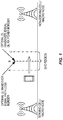
- Figure 1 illustrates a traditional HSPA deployment scenario with two nodes having a similar transmit power level.
- a mobile terminal (“user equipment,” or “UE,” in 3GPP terminology) moving from a serving cell towards a non-serving cell would enter the SHO region at point A. This is referred to as event 1A in 3GPP documentation.
- event 1A a serving cell change would occur, i.e., the non-serving cell becomes the serving cell and vice-versa.
- event 1D in 3GPP terms.
- the UE would leave the SHO region.
- 3GPP documentation refers to this as event 1B.
- the optimal downlink (DL) and uplink (UL) cell borders will coincide, i.e., the path loss from the UE to the two nodes will be equal at point B.
- the serving cell will always correspond to the best uplink.
- the UE might sometimes be power controlled by the non-serving cell during SHO.
- the uplink control channel transmissions are received by the serving cell.
- the High-Speed Dedicated Physical Control Channel (HS-DPCCH) transmitted by the UE and scheduling information must be received in the serving cell.
- HS-DPCCH High-Speed Dedicated Physical Control Channel
- RRC Radio Resource Control
- HARQ Hybrid Automatic-Repeat Request
- WO 2012/050506 discloses a power control applied to a radio network controller when a user equipment is in communication with a serving radio base station and at least one other radio base station involves the radio network controller providing a quality representation of an uplink control channel from the user equipment to the serving radio base station.
- the radio network controller generates an updated power quality target for a reference control channel based on the quality representation and transmits the updated power quality target to at least one of the serving radio base station and the at least one other radio base station.
- Embodiments of the techniques disclosed herein and detailed below may be used to ensure reliable reception of essential uplink control information in relevant nodes when the communication link is weak, in scenarios where another uplink link in the active set is stronger and would normally dictate the power control mechanism.
- An example method is implemented in at least one network node of a wireless communication network serving a wireless device, where the wireless device is transmitting one or more uplink channels to each of a serving cell and at least one non-serving cell.
- inner-loop power control (ILPC) commands are sent to the wireless device in such a way that only ILPC commands transmitted by the serving cell affect the power of one or more control channels transmitted by the wireless device to the serving cell.
- ILPC inner-loop power control
- a power offset for a data channel transmitted by the wireless device to the at least one non-serving cell is adjusted, so as to compensate for an uplink-downlink power imbalance among the serving cell and the at least one non-serving cell.
- these operations are performed in response to determining that a power-imbalance is or may be present, based on a triggering condition.
- the triggering condition may be or include, for example, that: the wireless device has entered soft handover; the wireless device has entered soft handover involving cells having different transmit powers; one or more control channel qualities at the serving cell becomes bad, compared to a predetermined reference level; a data channel quality at the serving cell becomes bad, compared to a predetermined reference level; the estimated SIR or other signal quality measure at the serving cell is below a target level for longer than a predetermined period of time; a large link imbalance between the wireless device and the serving cell and the wireless device and the at least one non-serving cell is detected; and/or the wireless device sends a message to the network, the message indicating a link imbalance.
- ILPC commands are sent in such a way that only "UP" Transmit Power Control (TPC) commands are sent to the wireless device from the at least one non-serving cell, while “UP” and “DOWN” TPC commands are selectively sent to the wireless device from the serving cell to control the power of one or more control channels transmitted by the wireless device to the serving cell.
- TPC Transmit Power Control
- an active set for the wireless device is configured so as to include only the serving cell, so that an ILPC function in the wireless device responds only to TPC commands transmitted by the serving cell.
- the wireless device is otherwise configured to ignore TPC commands transmitted by the at least one non-serving cell.
- the example method is implemented at least partly in a Radio Network Controller (RNC), which controls the serving cell and/or at least one non-serving cell to send the ILPC commands in such a way that only ILPC commands transmitted by the serving cell affect the power of one or more control channels transmitted by the wireless device to the serving cell.
- RNC Radio Network Controller
- the adjusting of a power offset discussed above comprises adjusting a power offset for an uplink packet data channel.
- This uplink packet data channel may be an E-DCH Dedicated Physical Data Channel (E-DPDCH), for example.
- E-DPDCH E-DCH Dedicated Physical Data Channel
- a signal-to-interference ratio (SIR), signal-to-interference-plus-noise ratio (SINR) or other signal quality measure is estimated for an uplink control channel in the at least one non-serving cell, and the power offset is calculated based on a difference between the estimated signal quality measure and a control channel signal quality target or setpoint.
- the power offset to the wireless device is sent to the wireless device via a new reference gain factor. In others, the power offset to the wireless device is sent to the wireless device via a change in a serving grant. In some embodiments, the power offset is sent to the wireless device using high-level signaling, e.g., Radio Resource Control (RRC) signaling, while in others the power offset is sent to the wireless device using physical layer signaling, such as via a high-speed shared control channel (HS-SCCH) order.
- RRC Radio Resource Control
- HS-SCCH high-speed shared control channel
- an example network node apparatus includes a radio transceiver associated with a cell and configured to communicate with one or more wireless devices served by the first cell, and one or more processing circuits. These one or more processing circuits are adapted to configure a wireless device that is transmitting one or more uplink channels to the first cell and to at least one non-serving cell to respond to ILPC commands sent to the wireless device in such a way that only ILPC commands transmitted by the first cell affect the power of one or more control channels transmitted by the wireless device to the first cell.
- the processing circuits are further adapted to adjust a power offset for a data channel transmitted by the wireless device to the at least one non-serving cell so as to compensate for an uplink-downlink power imbalance among the first cell and the at least one non-serving cell.
- Still other embodiments include a wireless communication system that includes a serving cell transceiver associated with a serving cell and configured to receive at least one uplink channel from a wireless device served by the serving cell, one or more non-serving cell transceivers, each associated with a non-serving cell and configured to receive at least one uplink channel from the wireless device, simultaneously with said serving cell transceiver receiving an uplink channel from the wireless device, and one or more processing circuits associated with one or more of the serving cell transceiver, the one or more non-serving cell transceivers, and a radio network controller.
- a serving cell transceiver associated with a serving cell and configured to receive at least one uplink channel from a wireless device served by the serving cell
- one or more non-serving cell transceivers each associated with a non-serving cell and configured to receive at least one uplink channel from the wireless device, simultaneously with said serving cell transceiver receiving an uplink channel from the wireless device
- processing circuits associated with one or more of the serving cell trans
- the processing circuits are adapted to control the serving cell transceiver and the one or more non-serving cell transceivers to send ILPC commands to the wireless device in such a way that only ILPC commands transmitted by the serving cell affect the power of one or more control channels transmitted by the wireless device to the serving cell, and to adjust a power offset for a data channel transmitted by the wireless device to the at least one non-serving cell so as to compensate for an uplink-downlink power imbalance among the serving cell and the at least one non-serving cell.
- nodes that communicate using the air interface are described, it will be appreciated that those nodes also have suitable radio communications circuitry.
- the technology can additionally be considered to be embodied entirely within any form of computer-readable memory, including non-transitory embodiments such as solid-state memory, magnetic disk, or optical disk containing an appropriate set of computer instructions that would cause a processor to carry out the techniques described herein.
- Hardware implementations of the presently disclosed techniques may include or encompass, without limitation, digital signal processor (DSP) hardware, a reduced instruction set processor, hardware (e.g., digital or analog) circuitry, including but not limited to application specific integrated circuit(s) (ASIC) and/or field programmable gate array(s) (FPGA(s)), and (where appropriate) state machines capable of performing such functions.
- DSP digital signal processor
- ASIC application specific integrated circuit
- FPGA field programmable gate array
- a computer is generally understood to comprise one or more processors or one or more controllers, and the terms computer, processor, and controller may be employed interchangeably.
- the functions may be provided by a single dedicated computer or processor or controller, by a single shared computer or processor or controller, or by a plurality of individual computers or processors or controllers, some of which may be shared or distributed.
- processor or “controller” also refers to other hardware capable of performing such functions and/or executing software, such as the example hardware recited above.
- HSPA High Speed Packet Access
- 3GPP 3rd Generation Partnership Project
- NodeB and UE should be understood to refer more broadly to base stations (or radio access nodes) and mobile terminals, respectively, where “mobile terminal” should be understood to encompass end-user and end-application wireless devices such as mobile telephones, smartphones, wireless-enabled tablets or personal computers, wireless machine-to-machine units, and the like.
- mobile terminal should be understood to encompass end-user and end-application wireless devices such as mobile telephones, smartphones, wireless-enabled tablets or personal computers, wireless machine-to-machine units, and the like.
- specific channels described in 3GPP standards are referred to herein, the disclosed techniques should be understood as applicable to similar channels in other wireless systems.
- LPNs low-power nodes
- RRU remote radio unit
- pico base station a pico base station
- micro base station allowing the expansion of network capacity in a cost-efficient way.
- a network consisting of traditional macro NodeBs as well as LPNs is referred to as a heterogeneous network.
- Two examples of use-cases for heterogeneous network deployment that may be envisioned are to fill coverage holes and to enhance capacity in localized traffic hotspots.
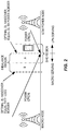
- the uplink (UL) and downlink (DL) cell borders will not necessarily coincide.
- An example of this is when a UE has a smaller uplink path loss to the LPN, while the strongest received power is from the macro NodeB.
- the UL is better served by the LPN, while the DL is provided by the serving macro NodeB.
- the optimal uplink handover point which is at the point at which there is an equal path loss to each node, is approximately halfway between the too nodes.
- the optimal downlink handover point which is the point at which the power levels for received downlink signals (e.g., the common pilot channels, or CPICHs) are equal, is closer to the LPN, since the LPN's transmit power is lower.
- the region between the equal path loss border and equal downlink received power border is referred to as an imbalance region.
- some fundamental problems may be encountered.
- a UE at position A would have the Macro Node as the serving cell, but would be power controlled towards the LPN. Due to this uplink/downlink (UL/DL) imbalance, the uplink towards the serving macro node could be very weak, which means that important control information, such as scheduling information or HS-DPCCH, might not be reliably decoded in the serving cell.
- a UE at position B would have the Macro Node as the serving cell, and would be power controlled towards the macro node as well.
- the UE in this case can cause excessive interference at the LPN.
- Radio Network Controller By tuning the Cell Individual Offset (CIO) parameter, for example, the handover border can be shifted towards the optimal UL border. Similarly, the IN_RANGE and OUT_RANGE parameters can be adjusted in order to extend the SHO region. The effects of these adjustments are illustrated in Figure 3 .
- the techniques disclosed herein include several different means for boosting uplink control channels when the communication link is weak. These techniques may be especially useful for addressing Scenarios 2 and 4 as listed above, for example.
- the techniques disclosed herein may be used to ensure reliable reception of essential uplink control information in relevant nodes when the communication link is weak, in scenarios where another uplink link in the active set is stronger and would normally dictate the power control mechanism.
- One benefit of the disclosed techniques is that they can be addressed to legacy users, i.e., to mobile terminals that are compliant only to standards that already exist.
- the serving cell is allowed to exclusively dictate the inner-loop power control (ILPC) commands, even when it does not correspond to the strongest uplink.
- ILPC inner-loop power control
- TPC Transmit Power Commands
- the power offsets for the power hungry E-DCH Dedicated Physical Data Channel (E-DPDCH) are reduced.
- E-DPDCH E-DPDCH power offsets are reduced, such that the total E-DPDCH power remains roughly the same in the LPN regardless of the magnitude of the UL/DL imbalance.
- the UE's inner-loop power control will only follow power control commands from the serving cell.
- the non-serving cells may be configured by RNC commands or otherwise controlled to always send "UP" TPC commands, at least during scenarios of interest, thus ensuring that the ILPC operation of the UE is dictated by only the serving cell's commands.
- Another approach is to configure the UE's active set so that only the serving cell is included. With this approach, the UE will only monitor TPC commands from the serving cell, again ensuring that the ILPC operation of the UE is dictated by only the serving cell's commands.
- Still another approach is to modify the UE so that it ignores commands from non-serving cells, at least during scenarios of interest.
- E-DPDCH power offset reduction If the serving cell is allowed to dictate the ILPC during power-imbalance scenarios, the UE might create excessive interference towards non-serving cells, especially when the UL/DL imbalance is large. The reason for this is that the uplink path loss might be significantly less from the UE to a non-serving cell compared to the uplink path loss between the UE and the serving cell.
- One way to address this is to adjust the power offsets used for the E-DPDCH. This is effective because the E-DPCH is especially power hungry, relative to other uplink channels. As a result, controlling the E-DPCH power has an outsized impact on the total interference.
- the E-DPCH power offsets are controlled so as to ensure that the total E-DPDCH power remains roughly constant in the non-serving cell irrespectively of how severe the imbalance is.
- the network needs to send the new values to the UE. Any one or more of several parameters may be used to communicate the information from the network to the UE:
- a second question is how to signal the new information to the UE.
- Alternatives for this include, but are not limited to:
- a major benefit of the disclosed techniques is that they can be used to protect all UL control information (HS-DPCCH, E-DPCCH or in-band E-DPDCH). Furthermore, most of the disclosed techniques are applicable to legacy users.
- FIG. 4 is a process flow diagram illustrating an example method implemented in at least one network node of a wireless communication network serving a UE, where the UE is transmitting one or more uplink channels to each of a serving cell and at least one non-serving cell.
- the illustrated method may be carried out in a Radio Network Controller (RNC), for example, or in one or more base stations, or in a combination of an RNC and one or more base stations.
- RNC Radio Network Controller
- the method in some embodiments may begin with first determining that a power-imbalance condition is or may be present, based on a triggering condition. In such embodiments, the subsequent operations are performed in response to said determined. This determining operation need not appear in all embodiments or take place in every instance, however. For this reason, block 410 is outline with a dashed outline, indicating that it is "optional" in the sense that it may not appear in every embodiments or in every instance that the method is carried out.
- the triggering condition may comprise one or more of the following, for example: the UE has entered soft handover; the UE has entered soft handover involving cells having different transmit powers; one or more control channel qualities at the serving cell becomes bad, compared to a predetermined reference level; a data channel quality at the serving cell becomes bad, compared to a predetermined reference level; the estimated SIR at the serving cell is below the SIR target for longer than a predetermined period of time; a large link imbalance between the UE and the serving cell and the UE and the at least one non-serving cell is detected; and the UE sends a message to the network, the message indicating a link imbalance.
- the illustrated method continues with the sending of inner-loop power control (ILPC) commands to the UE in such a way that only ILPC commands transmitted by the serving cell affect the power of one or more control channels transmitted by the UE to the serving cell.
- ILPC inner-loop power control
- the sending of ILPC commands to the UE may comprise sending only "UP" Transmit Power Control (TPC) commands to the UE from the at least one non-serving cell, while selectively sending "UP" and "DOWN” TPC commands to the UE from the serving cell to control the power of one or more control channels transmitted by the UE to the serving cell.
- TPC Transmit Power Control
- the sending of ILPC commands to the UE comprises configuring an active set for the UE to include only the serving cell, so that an ILPC function in the UE responds only to TPC commands transmitted by the serving cell.
- the sending of ILPC commands to the UE comprises configuring the UE to ignore TPC commands transmitted by the at least one non-serving cell. It will be appreciated that one or more of the operations illustrated in Figure 4 may be implemented at least partly in a Radio Network Controller (RNC).
- RNC Radio Network Controller
- the sending of ILPC commands to the UE may include controlling the serving cell and/or at least one non-serving cell to send the ILSPC commands in such a way that only ILPC commands transmitted by the serving cell affect the power of one or more control channels transmitted by the UE to the serving cell.
- the method continues with adjusting a power offset for a data channel transmitted by the UE to the at least one non-serving cell so as to compensate for an uplink-downlink power imbalance among the serving cell and the at least one non-serving cell.
- This may comprise, for example, adjusting a power offset for a data channel transmitted by the UE comprises adjusting a power offset for an uplink packet data channel.
- the uplink packet data channel in such embodiments may be an E-DCH Dedicated Physical Data Channel (E-DPDCH), for instance.
- adjusting the power offset for the data channel transmitted by the UE comprises estimating a signal-to-interference ratio (SIR), signal-to-interference-plus-noise ratio (SINR), or other signal quality measure for an uplink control channel in the at least one non-serving cell and calculating the power offset based on a difference between the estimated signal quality measure and a control channel target or setpoint for the signal quality measure.
- the power offset may be sent to the UE via a new reference gain factor or via a change in a serving grant, for example.
- the power offset may be sent using RLC or RRC signaling, in some embodiments, or using physical layer (L1) signaling, such as a via an HS-SCCH order, in others.
- network-based embodiments of the described solutions may be implemented in one or more nodes of a radio access network (RAN), such as a node in a 3GPP UMTS network.
- RAN radio access network
- nodes include, but are not limited to, a base station or RNC in a UMTS network.
- Figure 5 illustrates several network nodes that may implement or be involved in carrying out one or more of the techniques described above, including a radio network controller (RNC) 900, a first radio base station 800A, and second radio base station 800B.
- RNC radio network controller
- One of the radio base stations 800A and 800B may be an LPN while the other is a macro node, for example.
- the network in which these techniques are implemented may further include any additional elements suitable to support communication between wireless devices or between a wireless device and another communication device (such as a landline telephone).
- the illustrated network nodes may represent a network communication device that includes any suitable combination of hardware and/or software, these network nodes may, in particular embodiments, represent a device such as the example network node 900 shown in Figure 5 .
- the illustrated base station nodes 800A and 800B may represent network nodes that include any suitable combination of hardware and/or software, these network nodes may, in particular embodiments, represent devices having the particular configurations shown in Figure 5 , or equivalents thereto.
- the example network node 900 includes processing circuitry 920, a memory 930, and network interface circuitry 910.
- processing circuitry 920 may be provided by the processing circuitry 920 executing instructions stored on a computer-readable medium, such as the memory 930 shown in Figure 5 .
- Alternative embodiments of the network node 900 may include additional components beyond those shown in Figure 5 , which components may be responsible for providing certain aspects of the node's functionality, including any of the functionality described above and/or any functionality necessary to support the solutions described above.
- the example base stations 800A and 800B each include processing circuitry 820, a memory 830, radio circuitry 810, and at least one antenna.
- the processing circuitry 820 may comprise RF circuitry and baseband processing circuitry (not shown).
- some or all of the functionality described above as being provided by a base station, such as a NodeB in a UMTS system may be provided by the processing circuitry 820 executing instructions stored on a computer-readable medium, such as the memory 830 shown in Figure 5 .
- Alternative embodiments of base stations 800A and/or 800B may include additional components responsible for providing additional functionality, including any of the functionality identified above and/or any functionality necessary to support the solution described above.
- Terminal-based techniques and methods that complement the above-described methods are also possible, and may be implemented using radio circuitry and electronic data processing circuitry provided in a terminal.
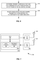
- a generalized method that may be carried out in a wireless device is illustrated in Figure 6
- Figure 7 illustrates components of an example wireless device apparatus.
- the illustrated method includes, as shown at block 610, with determining transmit power for a control channel to a serving cell in such a way that only ILPC commands received by the serving cell affect the power of the control channel. In some embodiments or in some instances, this is done by using an active set that has been configured so as to include only the serving cell, so that an ILPC function in the wireless device responds only to TPC commands transmitted by the serving cell. In other embodiments or in other instances, this is done by receiving only "UP" TPC commands from a non-serving cell or cells, while receiving both "UP" and “DOWN” TPC commands from the serving cell. In this scenario, the commands received from the serving cell will control the power of the control channel or channels transmitted by the wireless device.
- the wireless device is specifically configured to ignore TPC commands transmitted by a non-serving cell or cells.
- the active set may include one or more non-serving cell or cells, but the TPC commands from those non-serving cells are nevertheless ignored by the wireless device.
- This configuration may be performed in several ways - in one example, the wireless device receives configuration information from the network indicating that the TPC commands from non-serving cells should be ignored. This configuring may be based on Layer 1 signaling, for example, such as by an HS-SCCH order.
- the wireless device may be configured to recognize that it is in an uplink/downlink scenario, and to ignore TPC commands from non-serving cells in response to that recognition.
- the method further includes adjusting a power offset for a data channel transmitted by the wireless device.
- This adjusting may be in response to signaling from the network; several techniques for signaling the adjustment to the wireless device were discussed in detail above.
- Terminal 700 which may be a UE configured for operation with a 3GPP WCDMA network and that also supports Wi-Fi, for example, comprises a transceiver unit 720 for communicating with one or more base stations as well as a processing circuit 710 for processing the signals transmitted and received by the transceiver unit 720.
- Transceiver unit 720 includes a transmitter 725 coupled to one or more transmit antennas 728 and receiver 730 coupled to one or more receiver antennas 733. The same antenna(s) 728 and 733 may be used for both transmission and reception.
- Receiver 730 and transmitter 725 use known radio processing and signal processing components and techniques, typically according to a particular telecommunications standard such as the 3GPP standards for WCDMA.
- transmitter unit 720 may comprise separate radio and/or baseband circuitry for each of two or more different types of radio access network, such as radio/baseband circuitry adapted for UMTS operation and separate radio/baseband circuitry adapted for WiFi access.
- radio/baseband circuitry adapted for UMTS operation and separate radio/baseband circuitry adapted for WiFi access.
- the same applies to the antennas while in some cases one or more antennas may be used for accessing multiple types of networks, in other cases one or more antennas may be specifically adapted to a particular radio access network or networks.
- Processing circuit 710 comprises one or more processors 740 coupled to one or more memory devices 750 that make up a data storage memory 755 and a program storage memory 760.
- Processor 740 identified as CPU 740 in Figure 7 , may be a microprocessor, microcontroller, or digital signal processor, in some embodiments. More generally, processing circuit 710 may comprise a processor/firmware combination, or specialized digital hardware, or a combination thereof.
- Memory 750 may comprise one or several types of memory such as read-only memory (ROM), random-access memory, cache memory, flash memory devices, optical storage devices, etc.
- processing circuit 710 may include separate processing resources dedicated to one or several radio access technologies, in some embodiments. Again, because the various details and engineering tradeoffs associated with the design of baseband processing circuitry for mobile devices are well known and are unnecessary to a full understanding of the invention, additional details are not shown here.
- processing circuit 710 includes modulation and coding of transmitted signals and the demodulation and decoding of received signals.
- processing circuit 710 is adapted, using suitable program code stored in program storage memory 760, for example, to carry out one of the techniques described above in connection with Figure 6 .
- processing circuit 710 may be adapted, via suitable program code in memory 760, to determine transmit power for a control channel to a serving cell in such a way that only ILPC commands received by the serving cell affect the power of the control channel, and to adjust a power offset for a data channel transmitted by the wireless device.
- suitable program code in memory 760 may be adapted, via suitable program code in memory 760, to determine transmit power for a control channel to a serving cell in such a way that only ILPC commands received by the serving cell affect the power of the control channel, and to adjust a power offset for a data channel transmitted by the wireless device.
- a processing circuit is adapted, using suitable program code stored in memory, for example, to carry out one or more of the techniques described above, including any of the methods discussed in connection with Figures 4 and 6 .
- a processing circuit as adapted with program code stored in memory, can implement the process flow of Figure 4 or 6 , or variants thereof, using an arrangement of functional "modules," where the modules are computer programs or portions of computer programs executing on the processor circuit. Accordingly, any of the apparatus described above, whether forming all or part of a mobile terminal apparatus or a base station apparatus, can be understood as comprising one or more functional modules implemented with processing circuitry.
Landscapes
- Engineering & Computer Science (AREA)
- Computer Networks & Wireless Communication (AREA)
- Signal Processing (AREA)
- Quality & Reliability (AREA)
- Mobile Radio Communication Systems (AREA)
Claims (15)
- Procédé, mis en oeuvre dans au moins un noeud de réseau d'un réseau de communication sans fil desservant un dispositif sans fil, dans lequel le dispositif sans fil transmet un ou plusieurs canaux de liaison montante à chacune d'une cellule de desserte et d'au moins une cellule de non desserte, le procédé comprenant :l'envoi (420) de commandes de régulation de puissance en boucle intérieure, ILPC, au dispositif sans fil de telle manière qu'uniquement des commandes ILPC transmises par la cellule de desserte affectent la puissance d'un ou plusieurs canaux de commande transmis par le dispositif sans fil à la cellule de desserte ; etl'ajustement (430) d'un décalage de puissance pour un canal de données transmis par le dispositif sans fil à l'au moins une cellule de non desserte de manière à compenser un déséquilibre de puissance de liaison montante-liaison descendante entre la cellule de desserte et l'au moins une cellule de non desserte.
- Procédé selon la revendication 1, dans lequel ledit envoi (420) de commandes ILPC au dispositif sans fil comprend l'envoi uniquement de commandes de régulation de puissance de transmission, TPC, UP au dispositif sans fil à partir de l'au moins une cellule de non desserte, tout en envoyant sélectivement des commandes TPC UP et DOWN au dispositif sans fil à partir de la cellule de desserte pour réguler la puissance d'un ou plusieurs canaux de commande transmis par le dispositif sans fil à la cellule de desserte.
- Procédé selon la revendication 1, dans lequel ledit envoi (420) de commandes ILPC au dispositif sans fil comprend la configuration d'un ensemble actif pour le dispositif sans fil pour inclure uniquement la cellule de desserte, de sorte qu'une fonction ILPC dans le dispositif sans fil réponde uniquement à des commandes TPC transmises par la cellule de desserte.
- Procédé selon la revendication 1, dans lequel ledit envoi (420) de commandes ILPC au dispositif sans fil comprend la configuration du dispositif sans fil pour ignorer des commandes TPC transmises par l'au moins une cellule de non desserte.
- Procédé selon l'une quelconque des revendications 1 - 4, dans lequel ledit procédé est mis en oeuvre au moins partiellement dans un organe de commande de réseau radio, RNC, et dans lequel ledit envoi (420) de commandes ILPC au dispositif sans fil comprend la commande à la cellule de desserte et/ou à l'au moins une cellule de non desserte d'envoyer les commandes ILPC de telle manière qu'uniquement des commandes ILPC transmises par la cellule de desserte affectent la puissance d'un ou plusieurs canaux de commande transmis par le dispositif sans fil à la cellule de desserte.
- Procédé selon l'une quelconque des revendications 1 - 5, dans lequel l'ajustement (430) d'un décalage de puissance pour un canal de données transmis par le dispositif sans fil comprend l'ajustement d'un décalage de puissance pour un canal de données en paquets de liaison montante.
- Procédé selon la revendication 6, dans lequel le canal de données en paquets de liaison montante est un canal de données physique dédié E-DCH, E-DPDCH.
- Procédé selon l'une quelconque des revendications 1 - 7, dans lequel l'ajustement (430) d'un décalage de puissance pour un canal de données transmis par le dispositif sans fil comprend l'estimation d'un rapport de signal sur interférences, SIR, pour un canal de commande de liaison montante dans l'au moins une cellule de non desserte et le calcul du décalage de puissance sur la base d'une différence entre le SIR estimé et une cible ou un point de consigne de SIR de canal de commande.
- Procédé selon l'une quelconque des revendications 1 - 8, dans lequel l'ajustement (430) d'un décalage de puissance pour un canal de données transmis par le dispositif sans fil comprend l'envoi du décalage de puissance au dispositif sans fil par l'intermédiaire d'un nouveau facteur de gain de référence.
- Procédé selon l'une quelconque des revendications 1 - 8, dans lequel l'ajustement (430) d'un décalage de puissance pour un canal de données transmis par le dispositif sans fil comprend l'envoi du décalage de puissance au dispositif sans fil par l'intermédiaire d'un changement d'un octroi de desserte.
- Procédé selon l'une quelconque des revendications 1 - 10, dans lequel l'ajustement d'un décalage de puissance pour un canal de données transmis par le dispositif sans fil comprend l'envoi du décalage de puissance au dispositif sans fil en utilisant une signalisation de commande de ressources radio, RRC.
- Procédé selon l'une quelconque des revendications 1 - 10, dans lequel l'ajustement (430) d'un décalage de puissance pour un canal de données transmis par le dispositif sans fil comprend l'envoi du décalage de puissance au dispositif sans fil en utilisant une signalisation de couche physique.
- Procédé selon la revendication 12, dans lequel l'envoi du décalage de puissance au dispositif sans fil en utilisant une signalisation de couche physique comprend l'envoi du décalage de puissance dans un ordre de canal de commande partagé à grande vitesse, HS-SCCH.
- Appareil de noeud de réseau comprenant :un émetteur-récepteur radio (810A) associé à une cellule et configuré pour communiquer avec un ou plusieurs dispositifs sans fil desservis par la première cellule ; etun ou plusieurs circuits de traitement (820A, 920) aptes à effectuer :la configuration d'un dispositif sans fil qui transmet un ou plusieurs canaux de liaison montante à la première cellule et à au moins une cellule de non desserte pour répondre à des commandes de régulation de puissance en boucle intérieure, ILPC, envoyées au dispositif sans fil de telle manière qu'uniquement des commandes ILPC transmises par la première cellule affectent la puissance d'un ou plusieurs canaux de commande transmis par le dispositif sans fil à la première cellule ; etl'ajustement d'un décalage de puissance pour un canal de données transmis par le dispositif sans fil à l'au moins une cellule de non desserte de manière à compenser un déséquilibre de puissance de liaison montante-liaison descendante entre la première cellule et l'au moins une cellule de non desserte.
- Appareil de noeud de réseau selon la revendication 14, dans lequel l'un ou plusieurs circuits de traitement (820A, 920) sont aptes à configurer un ensemble actif pour le dispositif sans fil pour inclure uniquement la première cellule, de sorte qu'une fonction ILPC dans le dispositif sans fil réponde uniquement à des commandes TPC transmises par la première cellule.
Applications Claiming Priority (2)
| Application Number | Priority Date | Filing Date | Title |
|---|---|---|---|
| US201361822030P | 2013-05-10 | 2013-05-10 | |
| PCT/SE2014/050571 WO2014182236A1 (fr) | 2013-05-10 | 2014-05-09 | Commande de puissance de canaux de commande de liaison montante dans des réseaux heterogenes |
Publications (3)
| Publication Number | Publication Date |
|---|---|
| EP2995138A1 EP2995138A1 (fr) | 2016-03-16 |
| EP2995138A4 EP2995138A4 (fr) | 2017-01-04 |
| EP2995138B1 true EP2995138B1 (fr) | 2018-03-21 |
Family
ID=51867577
Family Applications (1)
| Application Number | Title | Priority Date | Filing Date |
|---|---|---|---|
| EP14794064.7A Active EP2995138B1 (fr) | 2013-05-10 | 2014-05-09 | Commande de puissance de canaux de commande de liaison montante dans des réseaux hétérogènes |
Country Status (4)
| Country | Link |
|---|---|
| US (1) | US9930622B2 (fr) |
| EP (1) | EP2995138B1 (fr) |
| CN (1) | CN105230087B (fr) |
| WO (1) | WO2014182236A1 (fr) |
Families Citing this family (9)
| Publication number | Priority date | Publication date | Assignee | Title |
|---|---|---|---|---|
| EP3193534A4 (fr) * | 2014-09-30 | 2017-07-26 | Huawei Technologies Co. Ltd. | Procédé de commande de terminal mobile et terminal mobile |
| CN107005950B (zh) * | 2014-12-01 | 2020-10-27 | 瑞典爱立信有限公司 | 用于管理无线设备的发射功率的方法和网络节点 |
| CN107231681A (zh) * | 2016-03-23 | 2017-10-03 | 中兴通讯股份有限公司 | 异构网络的上行功率控制方法、装置及无线网络控制器 |
| CN108882349A (zh) * | 2017-05-09 | 2018-11-23 | 中兴通讯股份有限公司 | 控制内环功控的方法和装置 |
| US10659207B2 (en) * | 2017-05-15 | 2020-05-19 | Qualcomm Incorporated | Uplink power control in new radio (NR) |
| CN111133802B (zh) * | 2017-09-27 | 2023-09-01 | 瑞典爱立信有限公司 | 网络节点功率控制 |
| US10798667B2 (en) * | 2018-06-08 | 2020-10-06 | Commscope Technologies Llc | Automatic transmit power control for radio points of a centralized radio access network that primarily provide wireless service to users located in an event area of a venue |
| WO2021185441A1 (fr) * | 2020-03-18 | 2021-09-23 | Nokia Solutions And Networks Oy | Commande de puissance d'émission d'un dispositif radio |
| EP4302528A4 (fr) * | 2021-03-01 | 2024-12-18 | Telefonaktiebolaget LM Ericsson (publ) | Réglage de paramètres de configuration de commande de puissance dans un réseau de communication avec transmission dl et ul découplée |
Family Cites Families (14)
| Publication number | Priority date | Publication date | Assignee | Title |
|---|---|---|---|---|
| CN101156333A (zh) * | 2005-03-29 | 2008-04-02 | 株式会社Ntt都科摩 | 发送功率控制方法及移动台 |
| US20080200202A1 (en) * | 2007-02-13 | 2008-08-21 | Qualcomm Incorporated | Power control with link imbalance on downlink and uplink |
| DE602007013826D1 (de) * | 2007-11-26 | 2011-05-19 | Ericsson Telefon Ab L M | Dpcch- und hs-dpcch-steuerung bei niedrigen gewährungen für e-dch |
| TWI508590B (zh) | 2009-02-09 | 2015-11-11 | Interdigital Patent Holdings | 利用多載波無線傳送器/接收器單元之上鏈功率控制裝置及方法 |
| CN102056276A (zh) * | 2009-11-10 | 2011-05-11 | 中兴通讯股份有限公司 | 一种基站确定下行内环功控方式的方法及装置 |
| US8804586B2 (en) * | 2010-01-11 | 2014-08-12 | Blackberry Limited | Control channel interference management and extended PDCCH for heterogeneous network |
| WO2012050507A1 (fr) * | 2010-10-12 | 2012-04-19 | Telefonaktiebolaget L M Ericsson (Publ) | Commande de puissance de liaison montante |
| US9554338B2 (en) * | 2011-02-18 | 2017-01-24 | Qualcomm Incorporated | Apparatus, method, and system for uplink control channel reception in a heterogeneous wireless communication network |
| CN103037490B (zh) | 2011-09-30 | 2016-06-08 | 上海贝尔股份有限公司 | 上行链路控制信道功率控制的方法和相应装置 |
| CN102647778B (zh) * | 2012-03-29 | 2014-12-10 | 华为技术有限公司 | 一种功率控制方法、功率控制系统以及相关设备 |
| CN102761920B (zh) * | 2012-06-29 | 2016-05-25 | 华为技术有限公司 | 通信方法、设备及系统 |
| US9338751B2 (en) * | 2012-10-23 | 2016-05-10 | Intel Deutschland Gmbh | Method and device for controlling a transmit power in a user equipment |
| US9961683B2 (en) * | 2013-04-05 | 2018-05-01 | Nokia Solutions And Networks Oy | UL serving link's role change in heterogeneous network |
| CN104105182B (zh) * | 2013-04-12 | 2019-05-10 | 中兴通讯股份有限公司 | 实现内环闭环功率控制的方法及基站 |
-
2014
- 2014-05-09 WO PCT/SE2014/050571 patent/WO2014182236A1/fr not_active Ceased
- 2014-05-09 US US14/378,052 patent/US9930622B2/en active Active
- 2014-05-09 EP EP14794064.7A patent/EP2995138B1/fr active Active
- 2014-05-09 CN CN201480026300.5A patent/CN105230087B/zh active Active
Non-Patent Citations (1)
| Title |
|---|
| None * |
Also Published As
| Publication number | Publication date |
|---|---|
| EP2995138A4 (fr) | 2017-01-04 |
| CN105230087A (zh) | 2016-01-06 |
| US9930622B2 (en) | 2018-03-27 |
| CN105230087B (zh) | 2018-12-04 |
| EP2995138A1 (fr) | 2016-03-16 |
| US20150257111A1 (en) | 2015-09-10 |
| WO2014182236A1 (fr) | 2014-11-13 |
Similar Documents
| Publication | Publication Date | Title |
|---|---|---|
| EP2995138B1 (fr) | Commande de puissance de canaux de commande de liaison montante dans des réseaux hétérogènes | |
| US9554338B2 (en) | Apparatus, method, and system for uplink control channel reception in a heterogeneous wireless communication network | |
| US9967867B2 (en) | UL control channel consideration for heterogeneous networks | |
| EP2915379B1 (fr) | Noeud de réseau, équipement utilisateur, procédés incorporés dans ceux-ci, produit de programme informatique et support de stockage informatique | |
| EP2915386B1 (fr) | Procédés et appareils pour amplifier une émission de canal dans un réseau | |
| US9398543B2 (en) | Radio network controller, a serving base station, a user equipment and methods therein | |
| US9743413B2 (en) | Network node, user node and methods for power boosting DPCCH | |
| US9756574B2 (en) | System and method for improving uplink control channels for weak communication links | |
| US10028183B2 (en) | Methods and network nodes in a wireless communication network for handling of uplink signals sent by a user equipment | |
| WO2014112919A1 (fr) | Gestion de contrôle de couche 1 dans des réseaux de communication sans fil hétérogènes |
Legal Events
| Date | Code | Title | Description |
|---|---|---|---|
| PUAI | Public reference made under article 153(3) epc to a published international application that has entered the european phase |
Free format text: ORIGINAL CODE: 0009012 |
|
| 17P | Request for examination filed |
Effective date: 20151207 |
|
| AK | Designated contracting states |
Kind code of ref document: A1 Designated state(s): AL AT BE BG CH CY CZ DE DK EE ES FI FR GB GR HR HU IE IS IT LI LT LU LV MC MK MT NL NO PL PT RO RS SE SI SK SM TR |
|
| AX | Request for extension of the european patent |
Extension state: BA ME |
|
| RIN1 | Information on inventor provided before grant (corrected) |
Inventor name: VON WRYCZA, PETER Inventor name: SAMUEL BEBAWY, MICHAEL Inventor name: WANG YP, ERIC Inventor name: LARSSON, ERIK |
|
| DAX | Request for extension of the european patent (deleted) | ||
| A4 | Supplementary search report drawn up and despatched |
Effective date: 20161202 |
|
| RIC1 | Information provided on ipc code assigned before grant |
Ipc: H04W 52/12 20090101ALI20161128BHEP Ipc: H04W 84/04 20090101ALI20161128BHEP Ipc: H04W 52/14 20090101ALI20161128BHEP Ipc: H04W 72/04 20090101ALI20161128BHEP Ipc: H04W 52/28 20090101ALI20161128BHEP Ipc: H04W 52/38 20090101ALI20161128BHEP Ipc: H04W 52/32 20090101ALI20161128BHEP Ipc: H04W 52/40 20090101ALI20161128BHEP Ipc: H04W 52/24 20090101AFI20161128BHEP |
|
| GRAP | Despatch of communication of intention to grant a patent |
Free format text: ORIGINAL CODE: EPIDOSNIGR1 |
|
| INTG | Intention to grant announced |
Effective date: 20171204 |
|
| GRAS | Grant fee paid |
Free format text: ORIGINAL CODE: EPIDOSNIGR3 |
|
| GRAA | (expected) grant |
Free format text: ORIGINAL CODE: 0009210 |
|
| AK | Designated contracting states |
Kind code of ref document: B1 Designated state(s): AL AT BE BG CH CY CZ DE DK EE ES FI FR GB GR HR HU IE IS IT LI LT LU LV MC MK MT NL NO PL PT RO RS SE SI SK SM TR |
|
| REG | Reference to a national code |
Ref country code: GB Ref legal event code: FG4D |
|
| REG | Reference to a national code |
Ref country code: CH Ref legal event code: EP |
|
| REG | Reference to a national code |
Ref country code: AT Ref legal event code: REF Ref document number: 982443 Country of ref document: AT Kind code of ref document: T Effective date: 20180415 |
|
| REG | Reference to a national code |
Ref country code: IE Ref legal event code: FG4D |
|
| REG | Reference to a national code |
Ref country code: DE Ref legal event code: R096 Ref document number: 602014022710 Country of ref document: DE |
|
| REG | Reference to a national code |
Ref country code: FR Ref legal event code: PLFP Year of fee payment: 5 |
|
| REG | Reference to a national code |
Ref country code: NL Ref legal event code: MP Effective date: 20180321 |
|
| PG25 | Lapsed in a contracting state [announced via postgrant information from national office to epo] |
Ref country code: FI Free format text: LAPSE BECAUSE OF FAILURE TO SUBMIT A TRANSLATION OF THE DESCRIPTION OR TO PAY THE FEE WITHIN THE PRESCRIBED TIME-LIMIT Effective date: 20180321 Ref country code: NO Free format text: LAPSE BECAUSE OF FAILURE TO SUBMIT A TRANSLATION OF THE DESCRIPTION OR TO PAY THE FEE WITHIN THE PRESCRIBED TIME-LIMIT Effective date: 20180621 Ref country code: LT Free format text: LAPSE BECAUSE OF FAILURE TO SUBMIT A TRANSLATION OF THE DESCRIPTION OR TO PAY THE FEE WITHIN THE PRESCRIBED TIME-LIMIT Effective date: 20180321 Ref country code: HR Free format text: LAPSE BECAUSE OF FAILURE TO SUBMIT A TRANSLATION OF THE DESCRIPTION OR TO PAY THE FEE WITHIN THE PRESCRIBED TIME-LIMIT Effective date: 20180321 Ref country code: CY Free format text: LAPSE BECAUSE OF FAILURE TO SUBMIT A TRANSLATION OF THE DESCRIPTION OR TO PAY THE FEE WITHIN THE PRESCRIBED TIME-LIMIT Effective date: 20180321 |
|
| REG | Reference to a national code |
Ref country code: LT Ref legal event code: MG4D |
|
| REG | Reference to a national code |
Ref country code: AT Ref legal event code: MK05 Ref document number: 982443 Country of ref document: AT Kind code of ref document: T Effective date: 20180321 |
|
| PG25 | Lapsed in a contracting state [announced via postgrant information from national office to epo] |
Ref country code: RS Free format text: LAPSE BECAUSE OF FAILURE TO SUBMIT A TRANSLATION OF THE DESCRIPTION OR TO PAY THE FEE WITHIN THE PRESCRIBED TIME-LIMIT Effective date: 20180321 Ref country code: BG Free format text: LAPSE BECAUSE OF FAILURE TO SUBMIT A TRANSLATION OF THE DESCRIPTION OR TO PAY THE FEE WITHIN THE PRESCRIBED TIME-LIMIT Effective date: 20180621 Ref country code: SE Free format text: LAPSE BECAUSE OF FAILURE TO SUBMIT A TRANSLATION OF THE DESCRIPTION OR TO PAY THE FEE WITHIN THE PRESCRIBED TIME-LIMIT Effective date: 20180321 Ref country code: LV Free format text: LAPSE BECAUSE OF FAILURE TO SUBMIT A TRANSLATION OF THE DESCRIPTION OR TO PAY THE FEE WITHIN THE PRESCRIBED TIME-LIMIT Effective date: 20180321 Ref country code: GR Free format text: LAPSE BECAUSE OF FAILURE TO SUBMIT A TRANSLATION OF THE DESCRIPTION OR TO PAY THE FEE WITHIN THE PRESCRIBED TIME-LIMIT Effective date: 20180622 |
|
| PG25 | Lapsed in a contracting state [announced via postgrant information from national office to epo] |
Ref country code: NL Free format text: LAPSE BECAUSE OF FAILURE TO SUBMIT A TRANSLATION OF THE DESCRIPTION OR TO PAY THE FEE WITHIN THE PRESCRIBED TIME-LIMIT Effective date: 20180321 Ref country code: PL Free format text: LAPSE BECAUSE OF FAILURE TO SUBMIT A TRANSLATION OF THE DESCRIPTION OR TO PAY THE FEE WITHIN THE PRESCRIBED TIME-LIMIT Effective date: 20180321 Ref country code: EE Free format text: LAPSE BECAUSE OF FAILURE TO SUBMIT A TRANSLATION OF THE DESCRIPTION OR TO PAY THE FEE WITHIN THE PRESCRIBED TIME-LIMIT Effective date: 20180321 Ref country code: AL Free format text: LAPSE BECAUSE OF FAILURE TO SUBMIT A TRANSLATION OF THE DESCRIPTION OR TO PAY THE FEE WITHIN THE PRESCRIBED TIME-LIMIT Effective date: 20180321 Ref country code: RO Free format text: LAPSE BECAUSE OF FAILURE TO SUBMIT A TRANSLATION OF THE DESCRIPTION OR TO PAY THE FEE WITHIN THE PRESCRIBED TIME-LIMIT Effective date: 20180321 Ref country code: IT Free format text: LAPSE BECAUSE OF FAILURE TO SUBMIT A TRANSLATION OF THE DESCRIPTION OR TO PAY THE FEE WITHIN THE PRESCRIBED TIME-LIMIT Effective date: 20180321 Ref country code: ES Free format text: LAPSE BECAUSE OF FAILURE TO SUBMIT A TRANSLATION OF THE DESCRIPTION OR TO PAY THE FEE WITHIN THE PRESCRIBED TIME-LIMIT Effective date: 20180321 |
|
| PG25 | Lapsed in a contracting state [announced via postgrant information from national office to epo] |
Ref country code: CZ Free format text: LAPSE BECAUSE OF FAILURE TO SUBMIT A TRANSLATION OF THE DESCRIPTION OR TO PAY THE FEE WITHIN THE PRESCRIBED TIME-LIMIT Effective date: 20180321 Ref country code: SK Free format text: LAPSE BECAUSE OF FAILURE TO SUBMIT A TRANSLATION OF THE DESCRIPTION OR TO PAY THE FEE WITHIN THE PRESCRIBED TIME-LIMIT Effective date: 20180321 Ref country code: AT Free format text: LAPSE BECAUSE OF FAILURE TO SUBMIT A TRANSLATION OF THE DESCRIPTION OR TO PAY THE FEE WITHIN THE PRESCRIBED TIME-LIMIT Effective date: 20180321 Ref country code: SM Free format text: LAPSE BECAUSE OF FAILURE TO SUBMIT A TRANSLATION OF THE DESCRIPTION OR TO PAY THE FEE WITHIN THE PRESCRIBED TIME-LIMIT Effective date: 20180321 |
|
| REG | Reference to a national code |
Ref country code: CH Ref legal event code: PL |
|
| PG25 | Lapsed in a contracting state [announced via postgrant information from national office to epo] |
Ref country code: PT Free format text: LAPSE BECAUSE OF FAILURE TO SUBMIT A TRANSLATION OF THE DESCRIPTION OR TO PAY THE FEE WITHIN THE PRESCRIBED TIME-LIMIT Effective date: 20180723 |
|
| REG | Reference to a national code |
Ref country code: DE Ref legal event code: R097 Ref document number: 602014022710 Country of ref document: DE |
|
| PLBE | No opposition filed within time limit |
Free format text: ORIGINAL CODE: 0009261 |
|
| STAA | Information on the status of an ep patent application or granted ep patent |
Free format text: STATUS: NO OPPOSITION FILED WITHIN TIME LIMIT |
|
| REG | Reference to a national code |
Ref country code: BE Ref legal event code: MM Effective date: 20180531 |
|
| PG25 | Lapsed in a contracting state [announced via postgrant information from national office to epo] |
Ref country code: MC Free format text: LAPSE BECAUSE OF FAILURE TO SUBMIT A TRANSLATION OF THE DESCRIPTION OR TO PAY THE FEE WITHIN THE PRESCRIBED TIME-LIMIT Effective date: 20180321 Ref country code: DK Free format text: LAPSE BECAUSE OF FAILURE TO SUBMIT A TRANSLATION OF THE DESCRIPTION OR TO PAY THE FEE WITHIN THE PRESCRIBED TIME-LIMIT Effective date: 20180321 |
|
| REG | Reference to a national code |
Ref country code: IE Ref legal event code: MM4A |
|
| 26N | No opposition filed |
Effective date: 20190102 |
|
| PG25 | Lapsed in a contracting state [announced via postgrant information from national office to epo] |
Ref country code: CH Free format text: LAPSE BECAUSE OF NON-PAYMENT OF DUE FEES Effective date: 20180531 Ref country code: LI Free format text: LAPSE BECAUSE OF NON-PAYMENT OF DUE FEES Effective date: 20180531 |
|
| PG25 | Lapsed in a contracting state [announced via postgrant information from national office to epo] |
Ref country code: LU Free format text: LAPSE BECAUSE OF NON-PAYMENT OF DUE FEES Effective date: 20180509 |
|
| PG25 | Lapsed in a contracting state [announced via postgrant information from national office to epo] |
Ref country code: IE Free format text: LAPSE BECAUSE OF NON-PAYMENT OF DUE FEES Effective date: 20180509 |
|
| PG25 | Lapsed in a contracting state [announced via postgrant information from national office to epo] |
Ref country code: SI Free format text: LAPSE BECAUSE OF FAILURE TO SUBMIT A TRANSLATION OF THE DESCRIPTION OR TO PAY THE FEE WITHIN THE PRESCRIBED TIME-LIMIT Effective date: 20180321 Ref country code: BE Free format text: LAPSE BECAUSE OF NON-PAYMENT OF DUE FEES Effective date: 20180531 |
|
| PG25 | Lapsed in a contracting state [announced via postgrant information from national office to epo] |
Ref country code: MT Free format text: LAPSE BECAUSE OF NON-PAYMENT OF DUE FEES Effective date: 20180509 |
|
| PG25 | Lapsed in a contracting state [announced via postgrant information from national office to epo] |
Ref country code: TR Free format text: LAPSE BECAUSE OF FAILURE TO SUBMIT A TRANSLATION OF THE DESCRIPTION OR TO PAY THE FEE WITHIN THE PRESCRIBED TIME-LIMIT Effective date: 20180321 |
|
| PG25 | Lapsed in a contracting state [announced via postgrant information from national office to epo] |
Ref country code: HU Free format text: LAPSE BECAUSE OF FAILURE TO SUBMIT A TRANSLATION OF THE DESCRIPTION OR TO PAY THE FEE WITHIN THE PRESCRIBED TIME-LIMIT; INVALID AB INITIO Effective date: 20140509 Ref country code: MK Free format text: LAPSE BECAUSE OF NON-PAYMENT OF DUE FEES Effective date: 20180321 |
|
| PG25 | Lapsed in a contracting state [announced via postgrant information from national office to epo] |
Ref country code: IS Free format text: LAPSE BECAUSE OF FAILURE TO SUBMIT A TRANSLATION OF THE DESCRIPTION OR TO PAY THE FEE WITHIN THE PRESCRIBED TIME-LIMIT Effective date: 20180721 |
|
| PGFP | Annual fee paid to national office [announced via postgrant information from national office to epo] |
Ref country code: DE Payment date: 20250529 Year of fee payment: 12 |
|
| PGFP | Annual fee paid to national office [announced via postgrant information from national office to epo] |
Ref country code: GB Payment date: 20250527 Year of fee payment: 12 |
|
| PGFP | Annual fee paid to national office [announced via postgrant information from national office to epo] |
Ref country code: FR Payment date: 20250526 Year of fee payment: 12 |