EP2995150B1 - Mobile station, network node, and methods for assigning resource blocks to the mobile station - Google Patents
Mobile station, network node, and methods for assigning resource blocks to the mobile station Download PDFInfo
- Publication number
- EP2995150B1 EP2995150B1 EP14728681.9A EP14728681A EP2995150B1 EP 2995150 B1 EP2995150 B1 EP 2995150B1 EP 14728681 A EP14728681 A EP 14728681A EP 2995150 B1 EP2995150 B1 EP 2995150B1
- Authority
- EP
- European Patent Office
- Prior art keywords
- maximum number
- resource blocks
- indication
- network node
- carriers
- Prior art date
- Legal status (The legal status is an assumption and is not a legal conclusion. Google has not performed a legal analysis and makes no representation as to the accuracy of the status listed.)
- Not-in-force
Links
- 238000000034 method Methods 0.000 title claims description 27
- 239000000969 carrier Substances 0.000 claims description 81
- 230000011664 signaling Effects 0.000 claims description 36
- 238000012545 processing Methods 0.000 claims description 35
- 230000005540 biological transmission Effects 0.000 claims description 19
- 230000001419 dependent effect Effects 0.000 claims description 12
- 230000009467 reduction Effects 0.000 description 26
- 230000009471 action Effects 0.000 description 10
- 230000009977 dual effect Effects 0.000 description 10
- 238000004891 communication Methods 0.000 description 6
- 230000008569 process Effects 0.000 description 5
- 230000008901 benefit Effects 0.000 description 4
- 230000010267 cellular communication Effects 0.000 description 3
- 230000001413 cellular effect Effects 0.000 description 3
- 230000008859 change Effects 0.000 description 2
- 238000010586 diagram Methods 0.000 description 2
- 238000005516 engineering process Methods 0.000 description 2
- 101100465000 Mus musculus Prag1 gene Proteins 0.000 description 1
- 230000003044 adaptive effect Effects 0.000 description 1
- 238000013459 approach Methods 0.000 description 1
- 238000010295 mobile communication Methods 0.000 description 1
- 230000004048 modification Effects 0.000 description 1
- 238000012986 modification Methods 0.000 description 1
Images






Classifications
-
- H—ELECTRICITY
- H04—ELECTRIC COMMUNICATION TECHNIQUE
- H04W—WIRELESS COMMUNICATION NETWORKS
- H04W72/00—Local resource management
- H04W72/04—Wireless resource allocation
- H04W72/044—Wireless resource allocation based on the type of the allocated resource
- H04W72/0446—Resources in time domain, e.g. slots or frames
-
- H—ELECTRICITY
- H04—ELECTRIC COMMUNICATION TECHNIQUE
- H04L—TRANSMISSION OF DIGITAL INFORMATION, e.g. TELEGRAPHIC COMMUNICATION
- H04L5/00—Arrangements affording multiple use of the transmission path
- H04L5/003—Arrangements for allocating sub-channels of the transmission path
- H04L5/0042—Intra-user or intra-terminal allocation
-
- H—ELECTRICITY
- H04—ELECTRIC COMMUNICATION TECHNIQUE
- H04L—TRANSMISSION OF DIGITAL INFORMATION, e.g. TELEGRAPHIC COMMUNICATION
- H04L5/00—Arrangements affording multiple use of the transmission path
- H04L5/0091—Signalling for the administration of the divided path, e.g. signalling of configuration information
- H04L5/0092—Indication of how the channel is divided
-
- H—ELECTRICITY
- H04—ELECTRIC COMMUNICATION TECHNIQUE
- H04W—WIRELESS COMMUNICATION NETWORKS
- H04W72/00—Local resource management
- H04W72/50—Allocation or scheduling criteria for wireless resources
- H04W72/51—Allocation or scheduling criteria for wireless resources based on terminal or device properties
-
- H—ELECTRICITY
- H04—ELECTRIC COMMUNICATION TECHNIQUE
- H04W—WIRELESS COMMUNICATION NETWORKS
- H04W88/00—Devices specially adapted for wireless communication networks, e.g. terminals, base stations or access point devices
- H04W88/02—Terminal devices
Definitions
- Embodiments herein relate to a mobile station and a network node, and to methods in the mobile station and the network node. In particular they relate to assigning resource blocks to the mobile station.
- MSs are also known as e.g. user equipments (UE), terminals, mobile terminals, wireless terminals, and/or wireless devices.
- MSs are enabled to communicate wirelessly in a cellular communications network or wireless communication system, sometimes also referred to as a cellular radio system or cellular networks.
- the communication may be performed e.g. between two MSs, between a MS and a regular telephone and/or between a MS and a server via a Radio Access Network (RAN) and possibly one or more core networks, comprised within the cellular communications network.
- RAN Radio Access Network
- MSs may further be referred to as mobile telephones, cellular telephones, laptops, tablet computers or surf plates with wireless capability, just to mention some further examples.
- the MSs in the present context may be, for example, portable, pocket-storable, hand-held, computer-comprised, or vehicle-mounted mobile devices, enabled to communicate voice and/or data, via the RAN, with another entity, such as another MS or a server.
- the cellular communications network covers a geographical area which is divided into cell areas, wherein each cell area being served by a radio network node.
- a cell is the geographical area where radio coverage is provided by the radio network node.
- the radio network node may e.g. be a base station such as a Radio Base Station (RBS), eNB, eNodeB, NodeB, B node, or Base Transceiver Station (BTS), depending on the technology and terminology used.
- the base stations may be of different classes such as e.g. macro eNodeB, home eNodeB or pico base station, based on transmission power and thereby also cell size.
- each radio network node may support one or several communication technologies.
- the radio network nodes communicate over the air interface operating on radio frequencies with the wireless terminals within range of the radio network node.
- the expression Downlink (DL) is used for the transmission path from the base station to the MS.
- the expression Uplink (UL) is used for the transmission path in the opposite direction i.e. from the MS to the base station.
- a resource block comprises information transmitted within a limited time duration, using a fixed bandwidth in the frequency domain.
- the limited time duration is e.g. a given timeslot (TS) within a Time Division Multiple Access (TDMA) frame, where each TDMA frame is received within the context of repeated 52-multiframes in General Packet Radio Service (GPRS)/Enhanced Data rates for Global Evolution (EDGE) systems.
- the fixed bandwidth in the frequency domain is e.g. a radio frequency carrier that supports repeated 52-multiframes on one or more TS in GPRS/EDGE systems.
- a MS will have the ability to process a certain maximum number of resource blocks based on the limitations of its processing power, e.g. 20 TSs received on a maximum of 8 radio frequency channels in GPRS/EDGE systems.
- the processing power of the MS is typically signaled from the MS to the network in one way or the other.
- GSM Global System for Mobile Communications
- BSC Base Station Controller
- SGSN Serving GPRS Support Node
- Downlink Dual Carrier is a feature introducing two parallel carriers transmitted on the DL to the same MS.
- DLDC Downlink Dual Carrier
- a single carrier transmission is extended to two separate carriers transmitted in parallel.
- DLDC is limited to the reception of at most two carriers in the DL.
- the carriers are received in separate receivers and hence the performance of each carrier is identical to reception of one single carrier.
- the number of carriers is limited to two due to cost, complexity and size reasons. Adding more carriers implies adding more receive chains which will increase cost and complexity, but also the size of a receiving device, such as the MS.
- DLMC Downlink Multi Carrier
- 3GPP Third Generation Partnership Project
- GERAN GSM/EDGE Radio Access Network
- DLMC utilizes a wide receiver filter and a single receive chain to simultaneously receive multiple carriers. Adding more carriers to the reception does not impost and implications on cost of the receiver and does not impact the size of the device.
- DLMC the main limitation of the number of resources possible to process by a device, such as a MS, is its processing power.
- the number of DL resource blocks that can be simultaneously processed by an MS during each Transmission Time Interval is determined by a signaled multislot class, a signaled maximum number of carriers supported, and a reduction parameter.
- the multislot class indicates the maximum number of DL timeslots that an MS can receive on a DL carrier during a TTI.
- the indicated maximum number of carriers supported is one or more of single carrier, dual carrier or multi carrier. Dual carrier and multi carrier are explicitly indicated, whereas single carrier does not require an explicit indication.
- the reduction parameter defines a reduction in the total number of TS and is currently indicated in an Information Element (IE) named Multislot Capability Reduction for Downlink Dual Carrier.
- IE Information Element
- this parameter is subtracted from the product of the maximum number of DL TS according to the multislot class and the maximum number of carriers supported.
- a network node such as a BSC will assign resource blocks to the MS, based on the above described signaled multislot class, maximum number of carriers and reduction parameter. This kind of capability signaling was developed in order to comply with DLDC operation.
- XP50696106 "Draft CR 24.008 Introduction of Downlink Multi-Carrier” ( Weg CR 24.008 Introduction of Downlink Multi-Carrier” ( Weg CR 24.008 Introduction of Downlink Multi-Carrier) ( Weg CR 24.008 Introduction of Downlink Multi-Carrier” ( Weg CR 24.008 Introduction of Downlink Multi-Carrier) ( Weg CR 24.008 Introduction of Downlink Multi-Carrier” ( Weg CR 24.008 Introduction of Downlink Multi-Carrier” ( Weg XP50696300, "DLMC - Working assumption” ( Weg kt LM Ericsson et al, 3GPP TSG-GERAN #57 GP-130263, Vienna, Austria, February 25th-March 1st, 2013 ) discloses working assumptions relating to the introduction of Downlink Multi-Carrier (DLMC).
- DLMC Downlink Multi-Carrier
- the object is achieved by a method in a network node for assigning resource blocks to a Mobile Station, MS.
- the MS is served by the network node.
- the MS is capable of downlink multicarrier operation.
- the network node receives from the MS, an indication of a maximum number of consecutive downlink timeslots that the MS is capable of receiving on a given carrier during a Transmission Time Interval, TTI.
- the network node further receives, from the MS, an indication of a maximum number of resource blocks that the MS is capable of processing during a TTI.
- the network node further receives, from the MS, an indication of a maximum number of carriers supported by the MS.
- the network node assigns resource blocks to the MS.
- the assigning is based on the received indication of a maximum number of consecutive downlink TS, on the received indication of a maximum number of resource blocks and on the received indication of a maximum number of carriers.
- the object is achieved by a network node for assigning resource blocks to a Mobile Station, MS.
- the MS is served by the network node.
- the MS is capable of downlink multicarrier operation.
- the network node is configured to receive, from the MS, an indication of a maximum number of during a Transmission Time Interval, TTI.
- the network node is further configured to receive, from the MS, an indication of a maximum number of resource blocks that the MS is capable of processing during a TTI.
- the network node is further configured to receive, from the MS, an indication of a maximum number of carriers supported by the MS.
- the network node is further configured to assign resource blocks to the MS.
- the assigning is based on the received indication of a maximum number of consecutive downlink TS, on the received indication of a maximum number of resource blocks and on the received indication of a maximum number of carriers.
- the object is achieved by a method in a Mobile Station, MS, for handling assignment of resource blocks.
- the MS is served by a network node.
- the MS is capable of downlink multicarrier operation.
- the MS signals, to the network node, an indication of a maximum number of consecutive downlink timeslots that the MS is capable of receiving on a given carrier during a Transmission Time Interval, TTI.
- the MS signals, to the network node, an indication of a maximum number of resource blocks that the MS is capable of processing during a TTI.
- the MS signals, to the network node, an indication of a maximum number of carriers supported by the MS.
- the MS receives from the network node, an assignment of resource blocks. The assignment is based on the signaled indication of a maximum number of consecutive downlink TS, on the signaled indication of a maximum number of resource blocks and on the signaled indication of a maximum number of carriers.
- the object is achieved by a Mobile Station, MS, for handling assignment of resource blocks.
- the MS is served by a network node.
- the MS is capable of downlink multicarrier operation.
- the MS is configured to signal, to the network node, an indication of a maximum number of consecutive downlink timeslots that the MS is capable of receiving on a given carrier during a Transmission Time Interval, TTI.
- the MS is further configured to signal, to the network node, an indication of a maximum number of resource blocks that the MS is capable of processing during a TTI.
- the MS is further configured to signal, to the network node, an indication of a maximum number of carriers supported by the MS.
- the MS is further configured to receive, from the network node, an assignment of resource blocks, which assignment is based on the signaled indication of a maximum number of consecutive downlink TS, on the signaled indication of a maximum number of resource blocks and on the signaled indication of a maximum number of carriers.
- an appropriate maximum number of carriers may be signaled. This allows the network to not only utilize the time domain in assigning timeslots to the MS on a single, or two carriers, but can also make full use of the frequency domain by letting the MS receive a high number of radio frequency channels simultaneously.
- the network node may assign resource blocks to the MS in a more flexible way than what would have been the case if the assigned resources would be coupled to a fixed number of radio frequency channels, as is done for data services in GSM today, both for legacy GSM operation but also when using reception of multiple simultaneous carriers with the downlink dual carrier, DLDC, feature.
- the DLDC adapted capacity signaling described above would have been used for the DLMC case, the maximum number of carriers signaled by the MS could have been lower than the actual capabilities of the MS.
- the network node would in that case assign resources on at most two radio frequency channels and would calculate the MS's maximum number of resource blocks in a predetermined manner, from a signaled timeslot reduction factor. This signaling would limit the flexibility of assigning resources and effectively reduce the user experience.
- Figure 1 illustrates how resource blocks may be assigned in single carrier operation.
- the maximum number of DL timeslots that an MS can receive on a DL carrier during a TTI is limited by the switching time capabilities of the MS, i.e. switching between transmission and reception.
- striped boxes indicate timeslots assigned for DL traffic.
- Black boxes indicate timeslots assigned for UL traffic.
- RT denotes switching time between receiving (Rx) and transmitting (Tx).
- TR denotes switching time between Tx and Rx.
- Figure 2 illustrates how resource blocks may be assigned in DLDC operation, according to current GSM functionality.
- the number of DL resource blocks that can be simultaneously processed by an MS during each TTI is then determined by a signaled multislot class, a signaled maximum number of carriers supported, and a signaled reduction parameter.
- the multislot class indicates the maximum number of DL timeslots that an MS can receive on a DL carrier during a TTI, and is limited by the switching time capabilities of the MS, i.e. switching between transmission and reception.
- the indicated maximum number of carriers supported is one or more of single carrier, dual carrier or multi carrier. Dual carrier and multi carrier are explicitly indicated, whereas single carrier does not require an explicit indication.
- the reduction parameter defines a reduction in the total number of timeslots and is currently indicated in an IE named Multislot Capability Reduction for Downlink Dual Carrier.
- the value of this parameter is subtracted from the product of the maximum number of DL timeslots according to the multislot class and the maximum number of carriers supported.
- the maximum number of carriers and the multislot capability reduction are related to the baseband processing power, such as how many TSs that can simultaneously be processed by the MS within one and the same TTI.
- a network node will assign resource blocks to the MS, based on the above described signaled multislot class, maximum number of carriers and reduction parameter. This kind of capability signaling was developed in order to comply with DLDC operation.
- an MS may signal a multislot class implying a capability of receiving up to 5 consecutive TS in the DL on a given carrier, and a Multislot Capability Reduction for Downlink Dual Carrier of 2.
- a multislot capability reduction the MS implicitly signals support of the DLDC feature.
- This capacity signaling tells the network that the MS is capable of processing resources spread on 5 TS multiplied by 2 carriers, minus 2 TS due to the multislot capacity reduction, i.e. 8 TS on the DL, during a TTI.
- the network may then assign resources to the MS e.g. as shown in Figure 2 , in which striped boxes indicate timeslots assigned for DL traffic, black boxes indicate timeslots assigned for UL traffic.
- RT denotes switching time between receiving (Rx) and transmitting (Tx).
- TR denotes switching time between Tx and Rx.
- Two TS 201, 202 are not assigned since the MS according to this example has indicated a multislot capability reduction of 2 TS.
- striped boxes indicate timeslots assigned for DL traffic
- black boxes indicate timeslots assigned for UL traffic
- the blank boxes within the frame denote TS which are not assigned due to the indicated multislot capability reduction of 3.
- the value of the multislot capability reduction must not be higher than the maximum number of TS per DL carrier, which is 5 in this case.
- a MS with a multislot capability of 5 TS and a capacity of 32 resource blocks could not have signaled a capacity of e.g. 8 carriers, since the MS would then have had to indicate a multislot capability reduction of 8, which is higher than 5, the maximum number or TS per DL carrier, and thus not allowed.
- using this kind of DLDC adapted signaling in DLMC operation implies that a MS capable of processing a certain number of carriers simultaneously may be forced to indicate a lower maximum number of carriers due to the signaling limitations.
- FIG. 4 depicts an example of a network 400 in which embodiments herein may be implemented.
- the network 400 may be a GSM network or any other wireless communications network in which embodiments herein may be implemented.
- a MS 410 operates in the network 400.
- the MS 410 may e.g. be a mobile terminal.
- the MS 410 may also be a laptop, a tablet computer or a surf plate with wireless capability, just to mention some further examples.
- the MS 410 in the present context may be, for example, portable, pocket-storable, hand-held, computer-comprised, or vehicle-mounted mobile devices, enabled to communicate voice and/or data, via the RAN, with another entity, such as another mobile station or a server.
- the MS 410 has access to a network node 420 via a radio air interface.
- the network node 420 may e.g. be a BSC or a SGSN.
- the network node 420 may also be base station, such as a BTS, a RBS, a NB or an eNB
- Example embodiments of a method in the network node 420 for assigning resource blocks to a MS 410, served by the network node 420, will now be described with reference to a flowchart depicted in Figure 5 .
- the method comprises the following actions, which actions may be taken in any suitable order.
- the method is described in a general way, here as seen from the network node's 420 point of view, relating to Figure 5 .
- the method will be described as seen from the MS's 410 point of view, relating to Figure 6 .
- the method will then be described in more detail below.
- the MS 410 is capable of DLMC operation.
- the network node 420 receives, from the MS 410, an indication of a maximum number of consecutive downlink timeslots that the MS 410 is capable of receiving on a given carrier during a Transmission Time Interval, TTI.
- the maximum number of consecutive downlink timeslots that the MS 410 is capable of receiving may be signaled by means of indicating a multislot class of the MS.
- the network node 420 receives, from the MS 410, an indication of a maximum number of resource blocks that the MS 410 is capable of processing during a TTI.
- the maximum number of resource blocks may be indicated independently of a maximum number of carriers.
- the indication of a maximum number of resource blocks that the MS 410 is capable of processing during a TTI is dependent on a modulation used. This means that the capacity signaling also allows for a feature dependent signalling. The maximum number of resource blocks signaled may then be dependent on a feature used on the resources, so that, for example, different values for the maximum number of resource blocks supported could be indicated depending on the modulation used. This means that multiple values for the maximum number of resource blocks supported could be signaled indicating MS capability on a per feature set, or feature set combination, basis.
- the network node 420 furhter receives, from the MS 410, an indication of a maximum number of carriers supported by the MS 410.
- the maximum number of carriers supported by the MS 410 is indicated in at least one of a MS Radio Access Capability information element, and a MS Classmark 3 information element. In that way, information elements already used in GSM for MS capability signaling are re-used.
- the network node 420 assigns resource blocks to the MS 410.
- the assigning is based on the received indication of a maximum number of consecutive downlink TS, on the received indication of a maximum number of resource blocks and on the received indication of a maximum number of carriers.
- the network node 420 may assign resources to the MS 410 in a more flexible way than if DLDC adapted capacity signaling would have been used. Then the full capacity of the MS may be used, e.g. such that resources may be assigned on all the carriers the MS is capable of processing simultaneously.
- Example embodiments of a method in the MS 410 for handling assignment of resource blocks to the MS 410 will now be described with reference to a flowchart depicted in Figure 6 .
- the MS 410 is served by the network node 420, and is capable of DLMC operation.
- the MS 410 signals, to the network node 420, an indication of a maximum number of consecutive downlink timeslots that the MS 410 is capable of receiving on a given carrier during a Transmission Time Interval, TTI.
- the maximum number of consecutive downlink timeslots that the MS 410 is capable of receiving may be signaled by means of indicating a multislot class of the MS. There may be no change in the multislot class signaled by the MS, as compared to a DLDC adapted capacity signaling, since the indicated multislot class is related to the switching times of the MS, which is not expected to change for an MS supporting Downlink Multicarrier, DLMC.
- the MS 410 signals, to the network node 420, an indication of a maximum number of resource blocks that the MS 410 is capable of processing during a TTI.
- the maximum number of resource blocks may be indicated independently of a maximum number of carriers.
- the indication of a maximum number of resource blocks that the MS 410 is capable of processing during a TTI is dependent on a modulation used.
- the capacity signaling also allows for a feature dependent signaling.
- the maximum number of resource blocks signaled may then be dependent on a feature used on the resources, so that, for example, different values for the maximum number of resource blocks supported could be indicated depending on the modulation used.
- the MS 410 further signals, to the network node 420, an indication of a maximum number of carriers supported by the MS 410.
- the maximum number of carriers supported by the MS 410 is indicated in at least one of a MS Radio Access Capability information element, and a MS Classmark 3 information element. In that way, information elements already used in GSM for MS capability signaling are used.
- the MS 410 receives, from the network node 420, an assignment of resource blocks.
- the assigning is based on the received indication of a maximum number of consecutive downlink TS, on the received indication of a maximum number of resource blocks and on the received indication of a maximum number of carriers.
- the network node 420 may assign resources to the MS 410 in a more flexible way than if DLDC adapted capacity signaling would have been used.
- Figure 7 depicts an example of how resource blocks may be assigned to an MS 410 which has signaled its capacity in accordance with embodiments herein.
- the MS has signaled a maximum number of carriers of 16, a maximum number of resource blocks of 32 and a multislot class indicative of a maximum of 5 consecutive downlink timeslots during a TTI.
- the network node 420 may then assign resource blocks to the MS 410 freely within the frame indicated in Figure 7 .
- striped boxes indicate timeslots assigned for DL traffic
- black boxes indicate timeslots assigned for UL traffic
- the blank boxes denote TS which are not assigned.
- Figure 8 , Figure 9 , Figure 10 and Figure 11 illustrate a further advantage with embodiments herein.
- embodiments herein enables an increased number of UL TS that can be assigned, while at the same time keeping the maximum DL throughput that can be realized unchanged.
- An increased UL bandwidth assignment may be achieved without reducing the DL bandwidth since increasing the number of UL TS assigned beyond 1 will no longer impose a corresponding reduction to the maximum number of resource blocks that can be assigned per DL carrier (i.e. the network node may assign more than 1 UL TS for the UL TBF and still be able to realize the maximum number of resource blocks supported by the MS on the DL.
- 1 TS is assigned on the UL, and assuming a capability of 32 resource blocks and a maximum number of carriers of 16 on the DL, the network node may assign resources freely within the frame indicated in Figure 8 .
- 3 TSs are assigned on the UL, and assuming a capability of 32 resource blocks and a maximum number of carriers of 16 on the DL, the network node may assign resources freely within the frame indicated in Figure 10 .
- the MS may utilize the maximum available baseband processing power through appropriate signaling to the network when some of the processing power voracious features, such as Mobile Station Receive Diversity (MSRD) and Voice services over Adaptive Multi-user channels on One Slot (VAMOS), are supported by that MS, but not used during that time.
- MSRD Mobile Station Receive Diversity
- VAMOS Voice services over Adaptive Multi-user channels on One Slot
- a further advantage with embodiment herein is that a single capability indicator defining the maximum number of resource blocks that can be processed by the mobile on the DL may be signaled.
- this single value would apply irrespective of the feature or feature combinations used.
- an additional Multislot capability reduction for an Enhanced Flexible Timeslot Assignment (EFTA) feature is needed since EFTA allows for more resources in the DL to be assigned.
- EFTA Enhanced Flexible Timeslot Assignment
- the MS could, in an implementation specific manner, factor in the most processing intense feature or feature set combinations it supports for which it can be assigned the largest value for the maximum number of resource blocks and still not exceed its processing capabilities.
- the granularity of the signaled indication can be chosen to suit current MS implementations. One alternative could for example be to allow for a granularity of 2 TS, starting from 6 TS in total.
- the maximum number of downlink timeslots possible to support may be from 6 TS up to 128 TS with an increment of 2 TS, i.e. [6,8,10,12,14,..]
- MS which is disclosed herein is capable not only of signaling the capabilities in question, but which also has these capabilities.
- the MS 410 is capable of downlink multicarrier operation,
- the network node 420 is configured to receive from the MS 410, an indication of a maximum number of consecutive downlink timeslots that the MS is capable of receiving on a given carrier during a Transmission Time Interval, TTI,
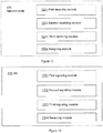
- the network node 420 comprises a first receiving module 1201, configured to receive the indication of a maximum number of consecutive downlink timeslots.
- the first receiving module 1201 may be comprised in a receiver circuit of the network node 420.
- the network node 420 is further configured to receive, from the MS 410, an indication of a maximum number of resource blocks that the MS 410 is capable of processing during a TTI.
- the network node 420 comprises a second receiving module 1202, configured to receive the indication of a maximum number of resource blocks.
- the second receiving module 1202 may be comprised in a receiver circuit of the network node 420.
- the indication of the maximum number of resource blocks that the MS 410 is capable of processing during a TTI is dependent on a modulation used.
- the network node 420 is further configured to receive, from the MS 410, an indication of a maximum number of carriers supported by the MS 410.
- the network node 420 comprises a third receiving module 1203, configured to receive the indication of a maximum number of carriers supported by the MS.
- the third receiving module 1203 may be comprised in a receiver circuit of the network node 420.
- the maximum number of carriers supported by the MS 410 is indicated in at least one of a MS Radio Access Capability information element, and a MS Classmark 3 information element.
- the network node 420 is further configured to assign resource blocks to the MS 410.
- the assigning is based on the received indication of a maximum number of consecutive downlink TS, on the received indication of a maximum number of resource blocks and on the received indication of a maximum number of carriers.
- the network node 420 comprises an assigning module 1204, configured to assign resource blocks to the MS.
- the assigning module 1204 may be comprised in a transmitter circuit of the network node 420.
- the MS 410 for handling assignment of resource blocks, as described above in relation to Figure 6 , is depicted in Figure 13 .
- the MS 410 is capable of downlink multicarrier operation, and is served by the network node 420,
- the MS 410 is configured to signal, to the network node 420, an indication of a maximum number of consecutive downlink timeslots that the MS is capable of receiving on a given carrier during a Transmission Time Interval, TTI.
- the MS 410 comprises a first signaling module 1301, configured to signal the indication of a maximum number of consecutive downlink timeslots.
- the first signaling module 1301 may be comprised in a transmitting circuit of the MS 410.
- the MS 410 is further configured to signal, to the network node 420, an indication of a maximum number of resource blocks that the MS 410 is capable of processing during a TTI.
- the MS 410 comprises a second signaling module 1302, configured to signal the indication of a maximum number of resource blocks.
- the second signaling module 1302 may be comprised in a transmitting circuit of the MS 410.
- the indication of the maximum number of resource blocks that the MS 410 is capable of processing during a TTI is dependent on a modulation used.
- the MS 410 is further configured to signal, to the network node 420, an indication of a maximum number of carriers supported by the MS 410.
- the MS 410 comprises a third signaling module 1303, configured to signal the indication of a maximum number of carriers supported by the MS.
- the third signaling module 1303 may be comprised in a transmitting circuit of the MS 410.
- the maximum number of carriers supported by the MS 410 is indicated in at least one of a MS Radio Access Capability information element, and a MS Classmark 3 information element.
- the MS 410 is further configured to receive an assignment of resource blocks from the netowork node 420.
- the assigning is based on the signaled indication of a maximum number of consecutive downlink TS, on the signaled indication of a maximum number of resource blocks and on the signaled indication of a maximum number of carriers.
- the MS 410 comprises a receiving module 1304, configured to receive the assignment of resource blocks.
- the receiving module 1304 may be comprised in a receiver circuit of the MS 410.
Landscapes
- Engineering & Computer Science (AREA)
- Signal Processing (AREA)
- Computer Networks & Wireless Communication (AREA)
- Mobile Radio Communication Systems (AREA)
Description
- Embodiments herein relate to a mobile station and a network node, and to methods in the mobile station and the network node. In particular they relate to assigning resource blocks to the mobile station.
- Communication devices such as mobile stations (MS) are also known as e.g. user equipments (UE), terminals, mobile terminals, wireless terminals, and/or wireless devices. MSs are enabled to communicate wirelessly in a cellular communications network or wireless communication system, sometimes also referred to as a cellular radio system or cellular networks. The communication may be performed e.g. between two MSs, between a MS and a regular telephone and/or between a MS and a server via a Radio Access Network (RAN) and possibly one or more core networks, comprised within the cellular communications network.
- MSs may further be referred to as mobile telephones, cellular telephones, laptops, tablet computers or surf plates with wireless capability, just to mention some further examples. The MSs in the present context may be, for example, portable, pocket-storable, hand-held, computer-comprised, or vehicle-mounted mobile devices, enabled to communicate voice and/or data, via the RAN, with another entity, such as another MS or a server.
- The cellular communications network covers a geographical area which is divided into cell areas, wherein each cell area being served by a radio network node. A cell is the geographical area where radio coverage is provided by the radio network node.
- The radio network node may e.g. be a base station such as a Radio Base Station (RBS), eNB, eNodeB, NodeB, B node, or Base Transceiver Station (BTS), depending on the technology and terminology used. The base stations may be of different classes such as e.g. macro eNodeB, home eNodeB or pico base station, based on transmission power and thereby also cell size.
- Further, each radio network node may support one or several communication technologies. The radio network nodes communicate over the air interface operating on radio frequencies with the wireless terminals within range of the radio network node. In the context of this disclosure, the expression Downlink (DL) is used for the transmission path from the base station to the MS. The expression Uplink (UL) is used for the transmission path in the opposite direction i.e. from the MS to the base station.
- With the rapid MS evolution, there is also a rapid increase in the need for additional processing power in the MSs to support more and more advanced radio network features, such as dual and multi-carrier reception.
- A resource block comprises information transmitted within a limited time duration, using a fixed bandwidth in the frequency domain. The limited time duration is e.g. a given timeslot (TS) within a Time Division Multiple Access (TDMA) frame, where each TDMA frame is received within the context of repeated 52-multiframes in General Packet Radio Service (GPRS)/Enhanced Data rates for Global Evolution (EDGE) systems. The fixed bandwidth in the frequency domain is e.g. a radio frequency carrier that supports repeated 52-multiframes on one or more TS in GPRS/EDGE systems.
- A MS will have the ability to process a certain maximum number of resource blocks based on the limitations of its processing power, e.g. 20 TSs received on a maximum of 8 radio frequency channels in GPRS/EDGE systems.
- The processing power of the MS is typically signaled from the MS to the network in one way or the other. In a Global System for Mobile Communications (GSM) system the processing power is signaled to a Base Station Controller (BSC) and/or a Serving GPRS Support Node (SGSN).
- Downlink Dual Carrier (DLDC) is a feature introducing two parallel carriers transmitted on the DL to the same MS. In DLDC, a single carrier transmission is extended to two separate carriers transmitted in parallel.
- DLDC is limited to the reception of at most two carriers in the DL. The carriers are received in separate receivers and hence the performance of each carrier is identical to reception of one single carrier. The number of carriers is limited to two due to cost, complexity and size reasons. Adding more carriers implies adding more receive chains which will increase cost and complexity, but also the size of a receiving device, such as the MS.
- A feature supporting multiple carriers on a DL, Downlink Multi Carrier (DLMC), is currently being standardized in Third Generation Partnership Project (3GPP) GSM/EDGE Radio Access Network (GERAN). DLMC utilizes a wide receiver filter and a single receive chain to simultaneously receive multiple carriers. Adding more carriers to the reception does not impost and implications on cost of the receiver and does not impact the size of the device. When using DLMC, the main limitation of the number of resources possible to process by a device, such as a MS, is its processing power.
- In current GSM functionality, the number of DL resource blocks that can be simultaneously processed by an MS during each Transmission Time Interval (TTI), is determined by a signaled multislot class, a signaled maximum number of carriers supported, and a reduction parameter. The multislot class indicates the maximum number of DL timeslots that an MS can receive on a DL carrier during a TTI. The indicated maximum number of carriers supported is one or more of single carrier, dual carrier or multi carrier. Dual carrier and multi carrier are explicitly indicated, whereas single carrier does not require an explicit indication. The reduction parameter defines a reduction in the total number of TS and is currently indicated in an Information Element (IE) named Multislot Capability Reduction for Downlink Dual Carrier. The value of this parameter is subtracted from the product of the maximum number of DL TS according to the multislot class and the maximum number of carriers supported. A network node, such as a BSC will assign resource blocks to the MS, based on the above described signaled multislot class, maximum number of carriers and reduction parameter. This kind of capability signaling was developed in order to comply with DLDC operation.
- XP50696106, "Draft CR 24.008 Introduction of Downlink Multi-Carrier" (Telefonaktiebolaget LM Ericsson et al, 3GPP TSG-GERAN #57 GP-130127, Vienna, Austria, February 25th-March 1 st, 2013) discloses modification of the MS Radio Access Capability IE in order to support the introduction of the Downlink Multi Carrier feature. , XP50696300, "DLMC - Working assumption" (Telefonaktiebolaget LM Ericsson et al, 3GPP TSG-GERAN #57 GP-130263, Vienna, Austria, February 25th-March 1st, 2013) discloses working assumptions relating to the introduction of Downlink Multi-Carrier (DLMC).
- It is an object of embodiments herein to provide a way of improving resource block assignment to a MS which is capable of Downlink Multi Carrier operation.
- According to a first aspect of embodiments herein, the object is achieved by a method in a network node for assigning resource blocks to a Mobile Station, MS. The MS is served by the network node. The MS is capable of downlink multicarrier operation. The network node receives from the MS, an indication of a maximum number of consecutive downlink timeslots that the MS is capable of receiving on a given carrier during a Transmission Time Interval, TTI. The network node further receives, from the MS, an indication of a maximum number of resource blocks that the MS is capable of processing during a TTI. The network node further receives, from the MS, an indication of a maximum number of carriers supported by the MS. The network node assigns resource blocks to the MS. The assigning is based on the received indication of a maximum number of consecutive downlink TS, on the received indication of a maximum number of resource blocks and on the received indication of a maximum number of carriers.
- According to a second aspect of embodiments herein, the object is achieved by a network node for assigning resource blocks to a Mobile Station, MS. The MS is served by the network node. The MS is capable of downlink multicarrier operation. The network node is configured to receive, from the MS, an indication of a maximum number of during a Transmission Time Interval, TTI. The network node is further configured to receive, from the MS, an indication of a maximum number of resource blocks that the MS is capable of processing during a TTI. The network node is further configured to receive, from the MS, an indication of a maximum number of carriers supported by the MS. The network node is further configured to assign resource blocks to the MS. The assigning is based on the received indication of a maximum number of consecutive downlink TS, on the received indication of a maximum number of resource blocks and on the received indication of a maximum number of carriers.
- According to a third aspect of embodiments herein, the object is achieved by a method in a Mobile Station, MS, for handling assignment of resource blocks. The MS is served by a network node. The MS is capable of downlink multicarrier operation. The MS signals, to the network node, an indication of a maximum number of consecutive downlink timeslots that the MS is capable of receiving on a given carrier during a Transmission Time Interval, TTI. The MS signals, to the network node, an indication of a maximum number of resource blocks that the MS is capable of processing during a TTI. The MS signals, to the network node, an indication of a maximum number of carriers supported by the MS. The MS receives from the network node, an assignment of resource blocks. The assignment is based on the signaled indication of a maximum number of consecutive downlink TS, on the signaled indication of a maximum number of resource blocks and on the signaled indication of a maximum number of carriers.
- According to a fourth aspect of embodiments herein, the object is achieved by a Mobile Station, MS, for handling assignment of resource blocks. The MS is served by a network node. The MS is capable of downlink multicarrier operation. The MS is configured to signal, to the network node, an indication of a maximum number of consecutive downlink timeslots that the MS is capable of receiving on a given carrier during a Transmission Time Interval, TTI. The MS is further configured to signal, to the network node, an indication of a maximum number of resource blocks that the MS is capable of processing during a TTI. The MS is further configured to signal, to the network node, an indication of a maximum number of carriers supported by the MS. The MS is further configured to receive, from the network node, an assignment of resource blocks, which assignment is based on the signaled indication of a maximum number of consecutive downlink TS, on the signaled indication of a maximum number of resource blocks and on the signaled indication of a maximum number of carriers.
- Since a maximum number of resource blocks which is independent of the maximum number of carriers is signaled, an appropriate maximum number of carriers may be signaled. This allows the network to not only utilize the time domain in assigning timeslots to the MS on a single, or two carriers, but can also make full use of the frequency domain by letting the MS receive a high number of radio frequency channels simultaneously.
- An advantage with embodiments herein is thus that the network node may assign resource blocks to the MS in a more flexible way than what would have been the case if the assigned resources would be coupled to a fixed number of radio frequency channels, as is done for data services in GSM today, both for legacy GSM operation but also when using reception of multiple simultaneous carriers with the downlink dual carrier, DLDC, feature. If the DLDC adapted capacity signaling described above would have been used for the DLMC case, the maximum number of carriers signaled by the MS could have been lower than the actual capabilities of the MS. The network node would in that case assign resources on at most two radio frequency channels and would calculate the MS's maximum number of resource blocks in a predetermined manner, from a signaled timeslot reduction factor. This signaling would limit the flexibility of assigning resources and effectively reduce the user experience.
- Examples of embodiments herein are described in more detail with reference to the attached drawings in which:
-
Figure 1 illustrates an exemplary resource block assignment in single carrier operation. -
Figure 2 illustrates an exemplary resource block assignment in DLDC operation. -
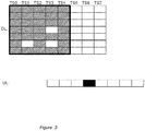
Figure 3 illustrates an exemplary resource block assignment in multi carrier operation, which resource block assignment is based on capacity signaling adapted for DLDC operation. -
Figure 4 schematically illustrates embodiments of a wireless communications network. -
Figure 5 is a flowchart depicting embodiments of a method in a network node. -
Figure 6 is a flowchart depicting embodiments of a method in a MS. -
Figure 7 illustrates an exemplary resource block assignment in DLMC operation, according to embodiments herein. -
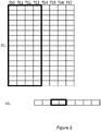
Figure 8 illustrates embodiments of how resource blocks may be assigned on the DL, when one timeslot is assigned for UL traffic. -
Figure 9 illustrates embodiments of how resource blocks may be assigned on the DL, when two timeslots are assigned for UL traffic. -
Figure 10 illustrates embodiments of how resource blocks may be assigned on the DL, when three timeslots are assigned for UL traffic. -
Figure 11 illustrates embodiments of how resource blocks may be assigned on the DL, when four timeslots are assigned for UL traffic. -
Figure 12 is a schematic block diagram illustrating embodiments of a network node. -
Figure 13 is a schematic block diagram illustrating embodiments of a MS. - As part of developing embodiments herein, some problems will first be identified and discussed.
-
Figure 1 illustrates how resource blocks may be assigned in single carrier operation. The maximum number of DL timeslots that an MS can receive on a DL carrier during a TTI is limited by the switching time capabilities of the MS, i.e. switching between transmission and reception. InFigure 1 , striped boxes indicate timeslots assigned for DL traffic. Black boxes indicate timeslots assigned for UL traffic. RT denotes switching time between receiving (Rx) and transmitting (Tx). TR denotes switching time between Tx and Rx. -
Figure 2 illustrates how resource blocks may be assigned in DLDC operation, according to current GSM functionality. The number of DL resource blocks that can be simultaneously processed by an MS during each TTI is then determined by a signaled multislot class, a signaled maximum number of carriers supported, and a signaled reduction parameter. The multislot class indicates the maximum number of DL timeslots that an MS can receive on a DL carrier during a TTI, and is limited by the switching time capabilities of the MS, i.e. switching between transmission and reception. The indicated maximum number of carriers supported is one or more of single carrier, dual carrier or multi carrier. Dual carrier and multi carrier are explicitly indicated, whereas single carrier does not require an explicit indication. The reduction parameter defines a reduction in the total number of timeslots and is currently indicated in an IE named Multislot Capability Reduction for Downlink Dual Carrier. The value of this parameter is subtracted from the product of the maximum number of DL timeslots according to the multislot class and the maximum number of carriers supported. The maximum number of carriers and the multislot capability reduction are related to the baseband processing power, such as how many TSs that can simultaneously be processed by the MS within one and the same TTI. - A network node will assign resource blocks to the MS, based on the above described signaled multislot class, maximum number of carriers and reduction parameter. This kind of capability signaling was developed in order to comply with DLDC operation.
- As an example, an MS may signal a multislot class implying a capability of receiving up to 5 consecutive TS in the DL on a given carrier, and a Multislot Capability Reduction for Downlink Dual Carrier of 2. By signaling a multislot capability reduction, the MS implicitly signals support of the DLDC feature. This capacity signaling tells the network that the MS is capable of processing resources spread on 5 TS multiplied by 2 carriers, minus 2 TS due to the multislot capacity reduction, i.e. 8 TS on the DL, during a TTI. The network may then assign resources to the MS e.g. as shown in
Figure 2 , in which striped boxes indicate timeslots assigned for DL traffic, black boxes indicate timeslots assigned for UL traffic. RT denotes switching time between receiving (Rx) and transmitting (Tx). TR denotes switching time between Tx and Rx. TwoTS - If the above described signaling from the MS is extended from DLDC to DLMC operation, a MS supporting DLMC would have to signal a multislot class, a maximum number of carriers and a multislot capability reduction. There are several drawbacks with applying this DLDC signaling approach to the DLMC case:
- Firstly, in order to allocate the maximum number of TS on the DL, so as to achieve maximum throughput, the signaled information must indicate a maximum number of carriers such that, when multiplied by the maximum number of TS per carrier corresponding to the signaled multislot class, the product does not exceed the maximum number of TS the MS can process simultaneously by more than "maximum number of TS per DL carrier". This requirement is due to that the largest number of TS that can be indicated by the multislot capability reduction is limited to "maximum number of TS per DL carrier". This has the net impact of forcing the network, such as a Base Station Subsystem (BSS), comprising a BTS and a Base Station Controller (BSC), to allocate the maximum number of TS on the DL over the smallest number of DL carriers minus 1 and thereby imposes a restriction in the assignment flexibility of the network. A situation may then occur in which the MS could potentially support the maximum number of TS it can process simultaneously on more than the maximum number of carriers it has signaled. That is, the maximum number of carriers signaled by the MS may in this case be lower than the actual capabilities of the MS.
- Secondly, when the BSS has been forced to assign TSs according to above description, increasing the number of UL TS assigned for an UL Temporary Block Flow (TBF) beyond 1 will impose a corresponding reduction to the maximum number of TS on the DL that can be assigned, for each DL carrier, and thereby eliminate any possibility of the network node ever realizing the maximum number of TS it can process on the DL simultaneously in the same radio block period, whenever 2 or more TS are assigned to the UL TBF.
- The problem of applying the legacy functionality to multi carrier operation is further illustrated in
Figure 3 . Assuming a baseband processing power of 32 resource blocks and a multislot capability of 5 consecutive TS, a capability of 7 carriers will have to be signaled, due to the limited flexibility of the signaling, even if the MS is in fact capable of processing the 32 resource blocks on more than 7 carriers. The MS will signal a multislot capability reduction of 3, such that 3 is subtracted from 35 - the product of 5 TS and 7 carriers - in order to secure that a capacity of 32 resource blocks is signaled. Resources may thus be assigned freely within the frame indicated inFigure 3 . InFigure 3 , striped boxes indicate timeslots assigned for DL traffic, black boxes indicate timeslots assigned for UL traffic, and the blank boxes within the frame denote TS which are not assigned due to the indicated multislot capability reduction of 3. As described above, the value of the multislot capability reduction must not be higher than the maximum number of TS per DL carrier, which is 5 in this case. According to this kind of DLDC adapted signaling, a MS with a multislot capability of 5 TS and a capacity of 32 resource blocks, could not have signaled a capacity of e.g. 8 carriers, since the MS would then have had to indicate a multislot capability reduction of 8, which is higher than 5, the maximum number or TS per DL carrier, and thus not allowed. Accordingly, using this kind of DLDC adapted signaling in DLMC operation implies that a MS capable of processing a certain number of carriers simultaneously may be forced to indicate a lower maximum number of carriers due to the signaling limitations. -
Figure 4 depicts an example of anetwork 400 in which embodiments herein may be implemented. Thenetwork 400 may be a GSM network or any other wireless communications network in which embodiments herein may be implemented. - A
MS 410 operates in thenetwork 400. TheMS 410 may e.g. be a mobile terminal. TheMS 410 may also be a laptop, a tablet computer or a surf plate with wireless capability, just to mention some further examples. TheMS 410 in the present context may be, for example, portable, pocket-storable, hand-held, computer-comprised, or vehicle-mounted mobile devices, enabled to communicate voice and/or data, via the RAN, with another entity, such as another mobile station or a server. - The
MS 410 has access to anetwork node 420 via a radio air interface. Thenetwork node 420 may e.g. be a BSC or a SGSN. Thenetwork node 420 may also be base station, such as a BTS, a RBS, a NB or an eNB - Example embodiments of a method in the
network node 420 for assigning resource blocks to aMS 410, served by thenetwork node 420, will now be described with reference to a flowchart depicted inFigure 5 . The method comprises the following actions, which actions may be taken in any suitable order. First, the method is described in a general way, here as seen from the network node's 420 point of view, relating toFigure 5 . Then, the method will be described as seen from the MS's 410 point of view, relating toFigure 6 . The method will then be described in more detail below. - According to embodiments herein, the
MS 410 is capable of DLMC operation. - The
network node 420 receives, from theMS 410, an indication of a maximum number of consecutive downlink timeslots that theMS 410 is capable of receiving on a given carrier during a Transmission Time Interval, TTI. The maximum number of consecutive downlink timeslots that theMS 410 is capable of receiving may be signaled by means of indicating a multislot class of the MS. - The
network node 420 receives, from theMS 410, an indication of a maximum number of resource blocks that theMS 410 is capable of processing during a TTI. The maximum number of resource blocks may be indicated independently of a maximum number of carriers. - In some embodiments the indication of a maximum number of resource blocks that the
MS 410 is capable of processing during a TTI, is dependent on a modulation used. This means that the capacity signaling also allows for a feature dependent signalling. The maximum number of resource blocks signaled may then be dependent on a feature used on the resources, so that, for example, different values for the maximum number of resource blocks supported could be indicated depending on the modulation used. This means that multiple values for the maximum number of resource blocks supported could be signaled indicating MS capability on a per feature set, or feature set combination, basis. - The
network node 420 furhter receives, from theMS 410, an indication of a maximum number of carriers supported by theMS 410. - In some embodiments, the maximum number of carriers supported by the
MS 410 is indicated in at least one of a MS Radio Access Capability information element, and a MS Classmark 3 information element. In that way, information elements already used in GSM for MS capability signaling are re-used. - According to embodiments herein, the
network node 420 assigns resource blocks to theMS 410. The assigning is based on the received indication of a maximum number of consecutive downlink TS, on the received indication of a maximum number of resource blocks and on the received indication of a maximum number of carriers. - Since the maximum number of carriers is independent of the maximum number of resource blocks, the
network node 420 may assign resources to theMS 410 in a more flexible way than if DLDC adapted capacity signaling would have been used. Then the full capacity of the MS may be used, e.g. such that resources may be assigned on all the carriers the MS is capable of processing simultaneously. - Example embodiments of a method in the
MS 410 for handling assignment of resource blocks to theMS 410, will now be described with reference to a flowchart depicted inFigure 6 . - The
MS 410 is served by thenetwork node 420, and is capable of DLMC operation. - The
MS 410 signals, to thenetwork node 420, an indication of a maximum number of consecutive downlink timeslots that theMS 410 is capable of receiving on a given carrier during a Transmission Time Interval, TTI. The maximum number of consecutive downlink timeslots that theMS 410 is capable of receiving may be signaled by means of indicating a multislot class of the MS. There may be no change in the multislot class signaled by the MS, as compared to a DLDC adapted capacity signaling, since the indicated multislot class is related to the switching times of the MS, which is not expected to change for an MS supporting Downlink Multicarrier, DLMC. - The
MS 410 signals, to thenetwork node 420, an indication of a maximum number of resource blocks that theMS 410 is capable of processing during a TTI. The maximum number of resource blocks may be indicated independently of a maximum number of carriers. - In some embodiments the indication of a maximum number of resource blocks that the
MS 410 is capable of processing during a TTI, is dependent on a modulation used. This means that the capacity signaling also allows for a feature dependent signaling. The maximum number of resource blocks signaled may then be dependent on a feature used on the resources, so that, for example, different values for the maximum number of resource blocks supported could be indicated depending on the modulation used. This means that multiple values for the maximum number of resource blocks supported could be signaled indicating MS capability on a per feature set, or feature set combination, basis. - The
MS 410 further signals, to thenetwork node 420, an indication of a maximum number of carriers supported by theMS 410. - In some embodiments, the maximum number of carriers supported by the
MS 410 is indicated in at least one of a MS Radio Access Capability information element, and a MS Classmark 3 information element. In that way, information elements already used in GSM for MS capability signaling are used. - According to embodiments herein, the
MS 410 receives, from thenetwork node 420, an assignment of resource blocks. The assigning is based on the received indication of a maximum number of consecutive downlink TS, on the received indication of a maximum number of resource blocks and on the received indication of a maximum number of carriers. - Since the maximum number of carriers is independent of the maximum number of resource blocks, the
network node 420 may assign resources to theMS 410 in a more flexible way than if DLDC adapted capacity signaling would have been used. - Various details of some possible embodiments are discussed below.
-
Figure 7 depicts an example of how resource blocks may be assigned to anMS 410 which has signaled its capacity in accordance with embodiments herein. In the exemplary embodiment depicted inFigure 7 , the MS has signaled a maximum number of carriers of 16, a maximum number of resource blocks of 32 and a multislot class indicative of a maximum of 5 consecutive downlink timeslots during a TTI. Thenetwork node 420 may then assign resource blocks to theMS 410 freely within the frame indicated inFigure 7 . InFigure 7 , striped boxes indicate timeslots assigned for DL traffic, black boxes indicate timeslots assigned for UL traffic, and the blank boxes denote TS which are not assigned. - As can be seen from a comparison between
Figure 3 andFigure 7 , allowing a larger number of carriers to be used - as inFigure 7 although the same maximum number of resource blocks is supported inFigure 3 and inFigure 7 - will allow the network, such as thenetwork node 420, to have more flexibility in what resource blocks to assign to theMS 410. In the legacy case, using DLDC adapted capacity signaling as inFigure 3 , the network can choose 32 assignments out of 35 while for the exemplary embodiment shown inFigure 7 , 32 assignments out of 80 can be chosen. -
Figure 8 ,Figure 9 ,Figure 10 andFigure 11 illustrate a further advantage with embodiments herein. As compared to a DLDC adapted capacity signaling, embodiments herein enables an increased number of UL TS that can be assigned, while at the same time keeping the maximum DL throughput that can be realized unchanged. - An increased UL bandwidth assignment may be achieved without reducing the DL bandwidth since increasing the number of UL TS assigned beyond 1 will no longer impose a corresponding reduction to the maximum number of resource blocks that can be assigned per DL carrier (i.e. the network node may assign more than 1 UL TS for the UL TBF and still be able to realize the maximum number of resource blocks supported by the MS on the DL.
- In
Figure 8 ,Figure 9 ,Figure 10 andFigure 11 , the improved ability for the network node to assign bandwidth on the UL, i.e. without necessitating a corresponding reduction in DL bandwidth, is shown. The same 32 blocks, i.e. the maximum number of resource blocks, may be scheduled on the DL for all 4 UL assignment cases shown inFigure 8 ,Figure 9 ,Figure 10 andFigure 11 , while allowing for a flexibility of 1-4 TS on the UL to be assigned for UL traffic. - In
Figure 8 ,1 TS is assigned on the UL, and assuming a capability of 32 resource blocks and a maximum number of carriers of 16 on the DL, the network node may assign resources freely within the frame indicated inFigure 8 . - In
Figure 9 ,2 TSs are assigned on the UL, and assuming a capability of 32 resource blocks and a maximum number of carriers of 16 on the DL, the network node may assign resources freely within the frame indicated inFigure 9 . - In
Figure 10 ,3 TSs are assigned on the UL, and assuming a capability of 32 resource blocks and a maximum number of carriers of 16 on the DL, the network node may assign resources freely within the frame indicated inFigure 10 . - In
Figure 11 ,4 TSs are assigned on the UL, and assuming a capability of 32 resource blocks and a maximum number of carriers of 16 on the DL, the network node may assign resources freely within the frame indicated inFigure 11 . - It is thus to be noted that although the assignment flexibility is progressively reduced on the DL as additional TS are assigned on the UL, e.g. "32 TS DL and 4 TS UL" as shown in
Figure 11 ., the increased UL bandwidth might be needed on a temporary basis to avoid stalling of a Radio Link Control (RLC) protocol by allowing an increased volume of Ack/Nack information to be transmitted. - A further advantage with embodiments herein is that the MS may utilize the maximum available baseband processing power through appropriate signaling to the network when some of the processing power voracious features, such as Mobile Station Receive Diversity (MSRD) and Voice services over Adaptive Multi-user channels on One Slot (VAMOS), are supported by that MS, but not used during that time.
- A further advantage with embodiment herein is that a single capability indicator defining the maximum number of resource blocks that can be processed by the mobile on the DL may be signaled.
- In other words, it is to be noted that this single value would apply irrespective of the feature or feature combinations used. For example, today for DLDC, an additional Multislot capability reduction for an Enhanced Flexible Timeslot Assignment (EFTA) feature is needed since EFTA allows for more resources in the DL to be assigned. However, if only a single value is provided for indicating the maximum number of resource blocks that can be processed, no EFTA specific IE is needed since the same value for maximum number of resource blocks would also apply in EFTA operation. When signaling a single value for this parameter the MS could, in an implementation specific manner, factor in the most processing intense feature or feature set combinations it supports for which it can be assigned the largest value for the maximum number of resource blocks and still not exceed its processing capabilities. The granularity of the signaled indication can be chosen to suit current MS implementations. One alternative could for example be to allow for a granularity of 2 TS, starting from 6 TS in total.
- Maximum number of resource blocks = [6,8,10,12,14....128]
- There is no need to start from a number lower than 5, which would indicate less baseband power than for a single carrier MS. Also, the maximum value need not be higher than 8*[max carriers], in this example 8*16=128, since the TDMA frame structure in GSM is limited to 8 TS.
- The maximum number of downlink timeslots possible to support may be from 6 TS up to 128 TS with an increment of 2 TS, i.e. [6,8,10,12,14,..]
- Examples of how to code the maximum number of downlink timeslots is shown below:
     Bits
     1 2 3 4 5 6
     0 0 0 0 0 0 Maximum number of downlink timeslots: 2
     0 0 0 0 0 1 Maximum number of downlink timeslots: 4
     ...
     1 1 1 1 0 0 Maximum number of downlink timeslots: 128
     1 1 1 1 0 1 Reserved
     1 1 1 1 1 1 Reserved
Claims (12)
- A method in a network node (420) for assigning resource blocks to a Mobile Station, MS, (410) served by the network node (420), wherein the MS (410) is capable of downlink multicarrier operation, the method comprising:receiving (501) from the MS (410), an indication of a maximum number of consecutive downlink timeslots that the MS is capable of receiving on a given carrier during a Transmission Time Interval, TTI,receiving (503) from the MS (410) an indication of a maximum number of carriers supported by the MS (410), and wherein the method is characterized by:receiving (502), from the MS (410), an indication of a maximum number of resource blocks that the MS (410) is capable of processing during a TTI, andassigning (504) resource blocks to the MS (410), wherein the assigning (504) is based on the received indication of a maximum number of consecutive downlink TS, on the received indication of a maximum number of resource blocks and on the received indication of a maximum number of carriers.
- The method according to claim 1, wherein the maximum number of carriers supported by the MS (410) is indicated in at least one ofa MS Radio Access Capability information element, anda MS Classmark 3 information element.
- The method according to any of claims 1 and 2, wherein the indication of a maximum number of resource blocks that the MS (410) is capable of processing during a TTI, is dependent on a modulation used.
- A network node (420) for assigning resource blocks to a Mobile Station, MS, (410) served by the network node (420), wherein the MS (410) is capable of downlink multicarrier operation, the network node being configured to:receive, from the MS (410), an indication of a maximum number of consecutive downlink timeslots that the MS is capable of receiving on a given carrier during a Transmission Time Interval, TTI,receive, from the MS (410), an indication of a maximum number of carriers supported by the MS (410), and wherein the network node (420) is characterized by being configured to:receive, from the MS (410), an indication of a maximum number of resource blocks that the MS (410) is capable of processing during a TTI, andassign resource blocks to the MS (410), wherein the assigning is based on the received indication of a maximum number of consecutive downlink TS, on the received indication of a maximum number of resource blocks and on the received indication of a maximum number of carriers.
- The network node according to claim 4, wherein the maximum number of carriers supported by the MS (410) is indicated in at least one ofa MS Radio Access Capability information element, anda MS Classmark 3 information element.
- The network node according to any of claims 4 and 5, wherein the indication of the maximum number of resource blocks that the MS (410) is capable of processing during a TTI, is dependent on a modulation used.
- A method in a Mobile Station, MS, (410) for handling assignment of resource blocks, wherein the MS (410) is served by a network node (420), and wherein the MS (410) is capable of downlink multicarrier operation, the method comprising:signaling (601), to the network node (420), an indication of a maximum number of consecutive downlink timeslots that the MS is capable of receiving on a given carrier during a Transmission Time Interval, TTI,signaling (603), to the network node (420), an indication of a maximum number of carriers supported by the MS (410), and wherein the method is characterized by:signaling (602), to the network node (420), an indication of a maximum number of resource blocks that the MS (410) is capable of processing during a TTI, andreceiving (604), from the network node (420), an assignment of resource blocks, which assignment is based on the signaled indication of a maximum number of consecutive downlink TS, on the signaled indication of a maximum number of resource blocks and on the signaled indication of a maximum number of carriers.
- The method according to claim 7, wherein the maximum number of carriers supported by the MS (410) is indicated in at least one ofa MS Radio Access Capability information element, anda MS Classmark 3 information element.
- The method according to any of claims 7 and 8, the indication of a maximum number of resource blocks that the MS (410) is capable of processing during a TTI, is dependent on a modulation used.
- A Mobile Station, MS, (410) for handling assignment of resource blocks, wherein the MS (410) is served by a network node (420), and wherein the MS (410) is capable of downlink multicarrier operation, the MS being configured to:signal, to the network node (420), an indication of a maximum number of consecutive downlink timeslots that the MS is capable of receiving on a given carrier during a Transmission Time Interval, TTI,signal, to the network node (420), an indication of a maximum number of carriers supported by the MS (410), and wherein the MS (410) is characterized by being configured to:signal, to the network node (420), an indication of a maximum number of resource blocks that the MS (410) is capable of processing during a TTI, andreceive, from the network node (420), an assignment of resource blocks, which assignment is based on the signaled indication of a maximum number of consecutive downlink TS, on the signaled indication of a maximum number of resource blocks and on the signaled indication of a maximum number of carriers.
- The MS (410) according to claim 10, wherein the maximum number of carriers supported by the MS (410) is indicated in at least one ofa MS Radio Access Capability information element, anda MS Classmark 3 information element.
- The MS according to any of claims 10 and11, wherein the indication of a maximum number of resource blocks that the MS (410) is capable of processing during a TTI, is dependent on a modulation used.
Applications Claiming Priority (2)
| Application Number | Priority Date | Filing Date | Title |
|---|---|---|---|
| US201361820338P | 2013-05-07 | 2013-05-07 | |
| PCT/SE2014/050548 WO2014182225A1 (en) | 2013-05-07 | 2014-05-05 | Mobile station, network node, and methods for assigning resource blocks to the mobile station |
Publications (2)
| Publication Number | Publication Date |
|---|---|
| EP2995150A1 EP2995150A1 (en) | 2016-03-16 |
| EP2995150B1 true EP2995150B1 (en) | 2017-04-05 |
Family
ID=50896471
Family Applications (1)
| Application Number | Title | Priority Date | Filing Date |
|---|---|---|---|
| EP14728681.9A Not-in-force EP2995150B1 (en) | 2013-05-07 | 2014-05-05 | Mobile station, network node, and methods for assigning resource blocks to the mobile station |
Country Status (5)
| Country | Link |
|---|---|
| US (1) | US9860895B2 (en) |
| EP (1) | EP2995150B1 (en) |
| BR (1) | BR112015026393A2 (en) |
| MY (1) | MY184070A (en) |
| WO (1) | WO2014182225A1 (en) |
Families Citing this family (2)
| Publication number | Priority date | Publication date | Assignee | Title |
|---|---|---|---|---|
| WO2018203814A1 (en) * | 2017-05-04 | 2018-11-08 | Telefonaktiebolaget Lm Ericsson (Publ) | Wireless device, network node, and methods performed thereby for handling a communication of blocks of physical channels or signals |
| CN115735370B (en) * | 2021-06-24 | 2025-10-17 | 北京小米移动软件有限公司 | Resource allocation method and device |
Family Cites Families (19)
| Publication number | Priority date | Publication date | Assignee | Title |
|---|---|---|---|---|
| US7397818B2 (en) * | 2001-10-19 | 2008-07-08 | Telefonaktiebolaget L M Ericsson (Publ) | Asymmetric bandwidth allocation |
| GB0607362D0 (en) * | 2006-04-12 | 2006-05-24 | Siemens Ag | A method of indicating mobile station capability to a network |
| ES2901556T3 (en) * | 2006-09-26 | 2022-03-22 | Optis Wireless Technology Llc | Communications scheme for channel quality information |
| WO2009002909A1 (en) * | 2007-06-25 | 2008-12-31 | Interdigital Technology Corporation | Method and apparatus for performing inter-radio access technology measurements to support geran band scan |
| US20090163158A1 (en) * | 2007-08-07 | 2009-06-25 | Interdigital Patent Holdings, Inc. | Support of downlink dual carriers and other features of evolved geran networks |
| IL203785A (en) * | 2007-09-12 | 2014-07-31 | Qualcomm Inc | Capacity increasing devices and methods for wireless communication |
| CN101616493B (en) * | 2008-06-27 | 2011-12-07 | 华为技术有限公司 | Data transmission method, network system and corresponding device |
| MX2011002704A (en) * | 2008-09-12 | 2011-04-21 | Qualcomm Inc | A METHOD AND APPLIANCE FOR SIGNALING A MOBILE DEVICE THAT ESTABLISHES TRAINING SEQUENCE CODES FOR USE IN A COMMUNICATION LINK. |
| KR101596071B1 (en) * | 2008-12-24 | 2016-02-19 | 파나소닉 인텔렉츄얼 프로퍼티 코포레이션 오브 아메리카 | Communication device and method |
| US8055294B2 (en) * | 2009-04-07 | 2011-11-08 | Lg Electronics Inc. | Control of uplink transmit power |
| JP5023170B2 (en) * | 2009-04-27 | 2012-09-12 | 株式会社エヌ・ティ・ティ・ドコモ | User apparatus, base station apparatus, and communication control method |
| KR101265646B1 (en) * | 2010-02-24 | 2013-05-24 | 엘지전자 주식회사 | Apparatus and method for transmitting ul feedback information for carrier over a ul feedback channel in a multicarrier system |
| CN102300316A (en) * | 2010-06-28 | 2011-12-28 | 中兴通讯股份有限公司 | Method and device for self-adaptively regulating uplink and downlink bandwidths |
| EP2683103B1 (en) * | 2011-02-18 | 2017-09-13 | BlackBerry Limited | Method and apparatus to report link quality measurements for downlink dual carrier operation |
| KR102401006B1 (en) * | 2011-09-30 | 2022-05-24 | 인터디지탈 패튼 홀딩스, 인크 | Device communication using a reduced channel bandwidth |
| US20130114571A1 (en) * | 2011-11-07 | 2013-05-09 | Qualcomm Incorporated | Coordinated forward link blanking and power boosting for flexible bandwidth systems |
| US20140010170A1 (en) * | 2011-12-09 | 2014-01-09 | Qualcomm Incorporated | Providing for mobility for flexible bandwidth carrier systems |
| US20130150045A1 (en) * | 2011-12-09 | 2013-06-13 | Qualcomm Incorporated | Providing for mobility for flexible bandwidth carrier systems |
| US9301302B2 (en) * | 2012-02-15 | 2016-03-29 | Telefonaktiebolaget Lm Ericsson (Publ) | Downlink multicarrier mobile communication network configuration |
-
2014
- 2014-05-05 EP EP14728681.9A patent/EP2995150B1/en not_active Not-in-force
- 2014-05-05 MY MYPI2015703514A patent/MY184070A/en unknown
- 2014-05-05 BR BR112015026393A patent/BR112015026393A2/en not_active Application Discontinuation
- 2014-05-05 WO PCT/SE2014/050548 patent/WO2014182225A1/en not_active Ceased
- 2014-05-05 US US14/787,876 patent/US9860895B2/en active Active
Non-Patent Citations (1)
| Title |
|---|
| None * |
Also Published As
| Publication number | Publication date |
|---|---|
| WO2014182225A1 (en) | 2014-11-13 |
| US20160073400A1 (en) | 2016-03-10 |
| MY184070A (en) | 2021-03-17 |
| EP2995150A1 (en) | 2016-03-16 |
| BR112015026393A2 (en) | 2017-07-25 |
| US9860895B2 (en) | 2018-01-02 |
Similar Documents
| Publication | Publication Date | Title |
|---|---|---|
| US12224871B2 (en) | Methods and apparatuses for transmitting and receiving sidelink information | |
| EP3627933B1 (en) | Communication method, terminal, and base station | |
| EP2797355B1 (en) | Wireless communication method and apparatus | |
| EP3883142B1 (en) | Sidelink communication method and terminal device | |
| CN110547031B (en) | Communication device, base station device, method, and recording medium | |
| KR101695114B1 (en) | Methods and devices for radio communication configuration | |
| US9807810B2 (en) | Physical channel design for network-assisted D2D | |
| CN114173420B (en) | Communication methods and devices | |
| US10985856B2 (en) | Multiple numerologies in a wireless communication system | |
| CN105122917A (en) | Dynamic TDD Configuration System Method | |
| WO2014109683A1 (en) | Over-the-air signaling for coordination of time-division duplexing | |
| CN112640525A (en) | Method and device for transmitting side link information, terminal device and network device | |
| CN110177397B (en) | User equipment, method and device in base station for wireless communication | |
| CN114342535A (en) | Method and device for transmitting and receiving uplink signal | |
| CN109937551B (en) | Radio node and method of operating a radio node | |
| WO2022253550A1 (en) | Spectrum extension for initial access | |
| EP2995150B1 (en) | Mobile station, network node, and methods for assigning resource blocks to the mobile station | |
| EP3806559A1 (en) | User equipment used for wireless communication and method and device of base station | |
| CN114143898B (en) | A method and device for user equipment and base station used for wireless communication | |
| CN115842598B (en) | Communication method and equipment | |
| WO2017111673A1 (en) | Computer program, carrier comprising computer program, network node and method therein for mitigating interference | |
| US12414114B2 (en) | Cross link interference mitigation for full duplex wireless systems | |
| US12538270B2 (en) | Uplink and downlink resource scheduling to mitigate interference | |
| CN103875269B (en) | The method and apparatus of wireless communication, network node | |
| WO2024112403A1 (en) | Interference mitigation in mobile wireless systems |
Legal Events
| Date | Code | Title | Description |
|---|---|---|---|
| PUAI | Public reference made under article 153(3) epc to a published international application that has entered the european phase |
Free format text: ORIGINAL CODE: 0009012 |
|
| 17P | Request for examination filed |
Effective date: 20150923 |
|
| AK | Designated contracting states |
Kind code of ref document: A1 Designated state(s): AL AT BE BG CH CY CZ DE DK EE ES FI FR GB GR HR HU IE IS IT LI LT LU LV MC MK MT NL NO PL PT RO RS SE SI SK SM TR |
|
| AX | Request for extension of the european patent |
Extension state: BA ME |
|
| DAX | Request for extension of the european patent (deleted) | ||
| GRAP | Despatch of communication of intention to grant a patent |
Free format text: ORIGINAL CODE: EPIDOSNIGR1 |
|
| RIC1 | Information provided on ipc code assigned before grant |
Ipc: H04W 72/04 20090101AFI20161004BHEP Ipc: H04W 88/02 20090101ALN20161004BHEP |
|
| RIC1 | Information provided on ipc code assigned before grant |
Ipc: H04W 88/02 20090101ALN20161011BHEP Ipc: H04W 72/04 20090101AFI20161011BHEP |
|
| INTG | Intention to grant announced |
Effective date: 20161103 |
|
| GRAS | Grant fee paid |
Free format text: ORIGINAL CODE: EPIDOSNIGR3 |
|
| GRAA | (expected) grant |
Free format text: ORIGINAL CODE: 0009210 |
|
| AK | Designated contracting states |
Kind code of ref document: B1 Designated state(s): AL AT BE BG CH CY CZ DE DK EE ES FI FR GB GR HR HU IE IS IT LI LT LU LV MC MK MT NL NO PL PT RO RS SE SI SK SM TR |
|
| REG | Reference to a national code |
Ref country code: GB Ref legal event code: FG4D |
|
| REG | Reference to a national code |
Ref country code: CH Ref legal event code: EP |
|
| REG | Reference to a national code |
Ref country code: AT Ref legal event code: REF Ref document number: 882882 Country of ref document: AT Kind code of ref document: T Effective date: 20170415 |
|
| REG | Reference to a national code |
Ref country code: IE Ref legal event code: FG4D |
|
| REG | Reference to a national code |
Ref country code: DE Ref legal event code: R096 Ref document number: 602014008360 Country of ref document: DE |
|
| REG | Reference to a national code |
Ref country code: FR Ref legal event code: PLFP Year of fee payment: 4 |
|
| REG | Reference to a national code |
Ref country code: NL Ref legal event code: MP Effective date: 20170405 |
|
| REG | Reference to a national code |
Ref country code: LT Ref legal event code: MG4D |
|
| REG | Reference to a national code |
Ref country code: AT Ref legal event code: MK05 Ref document number: 882882 Country of ref document: AT Kind code of ref document: T Effective date: 20170405 |
|
| PG25 | Lapsed in a contracting state [announced via postgrant information from national office to epo] |
Ref country code: NL Free format text: LAPSE BECAUSE OF FAILURE TO SUBMIT A TRANSLATION OF THE DESCRIPTION OR TO PAY THE FEE WITHIN THE PRESCRIBED TIME-LIMIT Effective date: 20170405 |
|
| PG25 | Lapsed in a contracting state [announced via postgrant information from national office to epo] |
Ref country code: ES Free format text: LAPSE BECAUSE OF FAILURE TO SUBMIT A TRANSLATION OF THE DESCRIPTION OR TO PAY THE FEE WITHIN THE PRESCRIBED TIME-LIMIT Effective date: 20170405 Ref country code: NO Free format text: LAPSE BECAUSE OF FAILURE TO SUBMIT A TRANSLATION OF THE DESCRIPTION OR TO PAY THE FEE WITHIN THE PRESCRIBED TIME-LIMIT Effective date: 20170705 Ref country code: HR Free format text: LAPSE BECAUSE OF FAILURE TO SUBMIT A TRANSLATION OF THE DESCRIPTION OR TO PAY THE FEE WITHIN THE PRESCRIBED TIME-LIMIT Effective date: 20170405 Ref country code: LT Free format text: LAPSE BECAUSE OF FAILURE TO SUBMIT A TRANSLATION OF THE DESCRIPTION OR TO PAY THE FEE WITHIN THE PRESCRIBED TIME-LIMIT Effective date: 20170405 Ref country code: GR Free format text: LAPSE BECAUSE OF FAILURE TO SUBMIT A TRANSLATION OF THE DESCRIPTION OR TO PAY THE FEE WITHIN THE PRESCRIBED TIME-LIMIT Effective date: 20170706 Ref country code: AT Free format text: LAPSE BECAUSE OF FAILURE TO SUBMIT A TRANSLATION OF THE DESCRIPTION OR TO PAY THE FEE WITHIN THE PRESCRIBED TIME-LIMIT Effective date: 20170405 Ref country code: FI Free format text: LAPSE BECAUSE OF FAILURE TO SUBMIT A TRANSLATION OF THE DESCRIPTION OR TO PAY THE FEE WITHIN THE PRESCRIBED TIME-LIMIT Effective date: 20170405 |
|
| PG25 | Lapsed in a contracting state [announced via postgrant information from national office to epo] |
Ref country code: LV Free format text: LAPSE BECAUSE OF FAILURE TO SUBMIT A TRANSLATION OF THE DESCRIPTION OR TO PAY THE FEE WITHIN THE PRESCRIBED TIME-LIMIT Effective date: 20170405 Ref country code: SE Free format text: LAPSE BECAUSE OF FAILURE TO SUBMIT A TRANSLATION OF THE DESCRIPTION OR TO PAY THE FEE WITHIN THE PRESCRIBED TIME-LIMIT Effective date: 20170405 Ref country code: RS Free format text: LAPSE BECAUSE OF FAILURE TO SUBMIT A TRANSLATION OF THE DESCRIPTION OR TO PAY THE FEE WITHIN THE PRESCRIBED TIME-LIMIT Effective date: 20170405 Ref country code: PL Free format text: LAPSE BECAUSE OF FAILURE TO SUBMIT A TRANSLATION OF THE DESCRIPTION OR TO PAY THE FEE WITHIN THE PRESCRIBED TIME-LIMIT Effective date: 20170405 Ref country code: BG Free format text: LAPSE BECAUSE OF FAILURE TO SUBMIT A TRANSLATION OF THE DESCRIPTION OR TO PAY THE FEE WITHIN THE PRESCRIBED TIME-LIMIT Effective date: 20170705 Ref country code: IS Free format text: LAPSE BECAUSE OF FAILURE TO SUBMIT A TRANSLATION OF THE DESCRIPTION OR TO PAY THE FEE WITHIN THE PRESCRIBED TIME-LIMIT Effective date: 20170805 |
|
| REG | Reference to a national code |
Ref country code: CH Ref legal event code: PL |
|
| REG | Reference to a national code |
Ref country code: DE Ref legal event code: R097 Ref document number: 602014008360 Country of ref document: DE |
|
| PG25 | Lapsed in a contracting state [announced via postgrant information from national office to epo] |
Ref country code: CZ Free format text: LAPSE BECAUSE OF FAILURE TO SUBMIT A TRANSLATION OF THE DESCRIPTION OR TO PAY THE FEE WITHIN THE PRESCRIBED TIME-LIMIT Effective date: 20170405 Ref country code: MC Free format text: LAPSE BECAUSE OF FAILURE TO SUBMIT A TRANSLATION OF THE DESCRIPTION OR TO PAY THE FEE WITHIN THE PRESCRIBED TIME-LIMIT Effective date: 20170405 Ref country code: EE Free format text: LAPSE BECAUSE OF FAILURE TO SUBMIT A TRANSLATION OF THE DESCRIPTION OR TO PAY THE FEE WITHIN THE PRESCRIBED TIME-LIMIT Effective date: 20170405 Ref country code: RO Free format text: LAPSE BECAUSE OF FAILURE TO SUBMIT A TRANSLATION OF THE DESCRIPTION OR TO PAY THE FEE WITHIN THE PRESCRIBED TIME-LIMIT Effective date: 20170405 Ref country code: SK Free format text: LAPSE BECAUSE OF FAILURE TO SUBMIT A TRANSLATION OF THE DESCRIPTION OR TO PAY THE FEE WITHIN THE PRESCRIBED TIME-LIMIT Effective date: 20170405 Ref country code: DK Free format text: LAPSE BECAUSE OF FAILURE TO SUBMIT A TRANSLATION OF THE DESCRIPTION OR TO PAY THE FEE WITHIN THE PRESCRIBED TIME-LIMIT Effective date: 20170405 |
|
| PLBE | No opposition filed within time limit |
Free format text: ORIGINAL CODE: 0009261 |
|
| STAA | Information on the status of an ep patent application or granted ep patent |
Free format text: STATUS: NO OPPOSITION FILED WITHIN TIME LIMIT |
|
| REG | Reference to a national code |
Ref country code: IE Ref legal event code: MM4A |
|
| PG25 | Lapsed in a contracting state [announced via postgrant information from national office to epo] |
Ref country code: CH Free format text: LAPSE BECAUSE OF NON-PAYMENT OF DUE FEES Effective date: 20170531 Ref country code: SM Free format text: LAPSE BECAUSE OF FAILURE TO SUBMIT A TRANSLATION OF THE DESCRIPTION OR TO PAY THE FEE WITHIN THE PRESCRIBED TIME-LIMIT Effective date: 20170405 Ref country code: LI Free format text: LAPSE BECAUSE OF NON-PAYMENT OF DUE FEES Effective date: 20170531 Ref country code: IT Free format text: LAPSE BECAUSE OF FAILURE TO SUBMIT A TRANSLATION OF THE DESCRIPTION OR TO PAY THE FEE WITHIN THE PRESCRIBED TIME-LIMIT Effective date: 20170405 |
|
| 26N | No opposition filed |
Effective date: 20180108 |
|
| PG25 | Lapsed in a contracting state [announced via postgrant information from national office to epo] |
Ref country code: LU Free format text: LAPSE BECAUSE OF NON-PAYMENT OF DUE FEES Effective date: 20170505 |
|
| REG | Reference to a national code |
Ref country code: BE Ref legal event code: MM Effective date: 20170531 |
|
| PG25 | Lapsed in a contracting state [announced via postgrant information from national office to epo] |
Ref country code: IE Free format text: LAPSE BECAUSE OF NON-PAYMENT OF DUE FEES Effective date: 20170505 |
|
| REG | Reference to a national code |
Ref country code: FR Ref legal event code: PLFP Year of fee payment: 5 |
|
| PG25 | Lapsed in a contracting state [announced via postgrant information from national office to epo] |
Ref country code: SI Free format text: LAPSE BECAUSE OF FAILURE TO SUBMIT A TRANSLATION OF THE DESCRIPTION OR TO PAY THE FEE WITHIN THE PRESCRIBED TIME-LIMIT Effective date: 20170405 |
|
| PG25 | Lapsed in a contracting state [announced via postgrant information from national office to epo] |
Ref country code: BE Free format text: LAPSE BECAUSE OF NON-PAYMENT OF DUE FEES Effective date: 20170531 |
|
| PG25 | Lapsed in a contracting state [announced via postgrant information from national office to epo] |
Ref country code: MT Free format text: LAPSE BECAUSE OF NON-PAYMENT OF DUE FEES Effective date: 20170505 |
|
| PG25 | Lapsed in a contracting state [announced via postgrant information from national office to epo] |
Ref country code: HU Free format text: LAPSE BECAUSE OF FAILURE TO SUBMIT A TRANSLATION OF THE DESCRIPTION OR TO PAY THE FEE WITHIN THE PRESCRIBED TIME-LIMIT; INVALID AB INITIO Effective date: 20140505 |
|
| PG25 | Lapsed in a contracting state [announced via postgrant information from national office to epo] |
Ref country code: CY Free format text: LAPSE BECAUSE OF FAILURE TO SUBMIT A TRANSLATION OF THE DESCRIPTION OR TO PAY THE FEE WITHIN THE PRESCRIBED TIME-LIMIT Effective date: 20170405 |
|
| PG25 | Lapsed in a contracting state [announced via postgrant information from national office to epo] |
Ref country code: MK Free format text: LAPSE BECAUSE OF FAILURE TO SUBMIT A TRANSLATION OF THE DESCRIPTION OR TO PAY THE FEE WITHIN THE PRESCRIBED TIME-LIMIT Effective date: 20170405 |
|
| PG25 | Lapsed in a contracting state [announced via postgrant information from national office to epo] |
Ref country code: TR Free format text: LAPSE BECAUSE OF FAILURE TO SUBMIT A TRANSLATION OF THE DESCRIPTION OR TO PAY THE FEE WITHIN THE PRESCRIBED TIME-LIMIT Effective date: 20170405 |
|
| PG25 | Lapsed in a contracting state [announced via postgrant information from national office to epo] |
Ref country code: PT Free format text: LAPSE BECAUSE OF FAILURE TO SUBMIT A TRANSLATION OF THE DESCRIPTION OR TO PAY THE FEE WITHIN THE PRESCRIBED TIME-LIMIT Effective date: 20170405 |
|
| PG25 | Lapsed in a contracting state [announced via postgrant information from national office to epo] |
Ref country code: AL Free format text: LAPSE BECAUSE OF FAILURE TO SUBMIT A TRANSLATION OF THE DESCRIPTION OR TO PAY THE FEE WITHIN THE PRESCRIBED TIME-LIMIT Effective date: 20170405 |
|
| PGFP | Annual fee paid to national office [announced via postgrant information from national office to epo] |
Ref country code: GB Payment date: 20220527 Year of fee payment: 9 Ref country code: FR Payment date: 20220525 Year of fee payment: 9 Ref country code: DE Payment date: 20220527 Year of fee payment: 9 |
|
| REG | Reference to a national code |
Ref country code: DE Ref legal event code: R119 Ref document number: 602014008360 Country of ref document: DE |
|
| GBPC | Gb: european patent ceased through non-payment of renewal fee |
Effective date: 20230505 |
|
| PG25 | Lapsed in a contracting state [announced via postgrant information from national office to epo] |
Ref country code: DE Free format text: LAPSE BECAUSE OF NON-PAYMENT OF DUE FEES Effective date: 20231201 Ref country code: GB Free format text: LAPSE BECAUSE OF NON-PAYMENT OF DUE FEES Effective date: 20230505 |
|
| PG25 | Lapsed in a contracting state [announced via postgrant information from national office to epo] |
Ref country code: FR Free format text: LAPSE BECAUSE OF NON-PAYMENT OF DUE FEES Effective date: 20230531 |