EP2995191A1 - Procédé de commande d'un processus de transbordement - Google Patents
Procédé de commande d'un processus de transbordement Download PDFInfo
- Publication number
- EP2995191A1 EP2995191A1 EP15172267.5A EP15172267A EP2995191A1 EP 2995191 A1 EP2995191 A1 EP 2995191A1 EP 15172267 A EP15172267 A EP 15172267A EP 2995191 A1 EP2995191 A1 EP 2995191A1
- Authority
- EP
- European Patent Office
- Prior art keywords
- control device
- signal
- harvester
- transport vehicle
- transfer
- Prior art date
- Legal status (The legal status is an assumption and is not a legal conclusion. Google has not performed a legal analysis and makes no representation as to the accuracy of the status listed.)
- Granted
Links
Images

Classifications
-
- A—HUMAN NECESSITIES
- A01—AGRICULTURE; FORESTRY; ANIMAL HUSBANDRY; HUNTING; TRAPPING; FISHING
- A01D—HARVESTING; MOWING
- A01D41/00—Combines, i.e. harvesters or mowers combined with threshing devices
- A01D41/12—Details of combines
- A01D41/127—Control or measuring arrangements specially adapted for combines
- A01D41/1274—Control or measuring arrangements specially adapted for combines for drives
-
- A—HUMAN NECESSITIES
- A01—AGRICULTURE; FORESTRY; ANIMAL HUSBANDRY; HUNTING; TRAPPING; FISHING
- A01D—HARVESTING; MOWING
- A01D41/00—Combines, i.e. harvesters or mowers combined with threshing devices
- A01D41/12—Details of combines
- A01D41/127—Control or measuring arrangements specially adapted for combines
- A01D41/1278—Control or measuring arrangements specially adapted for combines for automatic steering
-
- A—HUMAN NECESSITIES
- A01—AGRICULTURE; FORESTRY; ANIMAL HUSBANDRY; HUNTING; TRAPPING; FISHING
- A01D—HARVESTING; MOWING
- A01D43/00—Mowers combined with apparatus performing additional operations while mowing
- A01D43/06—Mowers combined with apparatus performing additional operations while mowing with means for collecting, gathering or loading mown material
- A01D43/07—Mowers combined with apparatus performing additional operations while mowing with means for collecting, gathering or loading mown material in or into a trailer
- A01D43/073—Mowers combined with apparatus performing additional operations while mowing with means for collecting, gathering or loading mown material in or into a trailer with controllable discharge spout
-
- A—HUMAN NECESSITIES
- A01—AGRICULTURE; FORESTRY; ANIMAL HUSBANDRY; HUNTING; TRAPPING; FISHING
- A01D—HARVESTING; MOWING
- A01D43/00—Mowers combined with apparatus performing additional operations while mowing
- A01D43/08—Mowers combined with apparatus performing additional operations while mowing with means for cutting up the mown crop, e.g. forage harvesters
- A01D43/086—Mowers combined with apparatus performing additional operations while mowing with means for cutting up the mown crop, e.g. forage harvesters and means for collecting, gathering or loading mown material
- A01D43/087—Mowers combined with apparatus performing additional operations while mowing with means for cutting up the mown crop, e.g. forage harvesters and means for collecting, gathering or loading mown material with controllable discharge spout
-
- A—HUMAN NECESSITIES
- A01—AGRICULTURE; FORESTRY; ANIMAL HUSBANDRY; HUNTING; TRAPPING; FISHING
- A01F—PROCESSING OF HARVESTED PRODUCE; HAY OR STRAW PRESSES; DEVICES FOR STORING AGRICULTURAL OR HORTICULTURAL PRODUCE
- A01F12/00—Parts or details of threshing apparatus
- A01F12/58—Control devices; Brakes; Bearings
Definitions
- the present invention relates to a method for controlling a transfer process according to the preamble of claim 1 and a self-propelled harvesting machine according to the preamble of claim 14.
- a method for controlling an overloading process during a current harvesting process and a self-propelled harvesting machine of the type mentioned are from the WO 2013/096593 A1 known. It describes a combine harvester with a transfer device and a control device, which is set up to receive and evaluate control signals from a support vehicle. Based on the evaluation of the external control signal, the operation of the transfer device of the combine harvester is influenced. If the situation arises during the transfer process from the combine harvester to the accompanying vehicle that an obstacle appears along the route of the escort vehicle, the escort vehicle makes an evasive movement. The evasive movement causes the transfer process to be interrupted as a result of the signal sent by the support vehicle to avoid crop losses. The control of the transfer process always takes place in response to an external control signal, which reflects only the operating situation of the support vehicle.
- the transfer process that is, the switching on and off of the transfer device, during the current harvesting process is controlled manually by the operator of the harvester.
- the occurrence of a critical operating situation during the transfer process which is generally signaled by a warning or error message on a display device of the operator's harvester, leads to the fact that the operator is generally dedicated to the elimination of this critical operating situation and thereby the current overcharge process, at least for a short time disregards. This usually leads to crop losses.
- the transfer process requires additional drive power that must be provided by the harvester. Accordingly, the remaining work organs of the harvester during the duration of the transfer process is less drive power to disposal. If an overload situation occurs on one of the work organs, the speed of advance is greatly reduced in response to this. This has the consequence that between the accompanying vehicle and the harvester a speed difference occurs, which in turn leads to overload losses, since the operator of the escort vehicle can not respond in the same way in a timely manner to the Vorfahren yorks selectedung the harvester.
- the object of the present invention is to provide a method for controlling an overhaul process taking place during the current harvesting operation as well as a harvesting machine which minimizes the occurrence of overload losses during critical operating situations of the harvesting machine.
- monitoring of the operating situation of the harvesting machine be carried out during the transfer process by the control device and that upon detection of a critical operating situation by the control device automatically switching off the transfer device is initiated.
- the operator is relieved of having to take care of the overloading process in addition to the assessment and subsequent rectification of this situation.
- the shutdown of the transfer device automatically releases drive power.
- the drive power released by the interruption of the transfer process can be assigned by the control device to at least one operating member.
- the assignment of the released drive power can be carried out as a function of a workstation signaling an overload situation.
- the overload situation can be mitigated or turned off.
- At least one signal representing an operating situation can be transmitted to the control device, which signal is evaluated by the control device for detecting the operating situation.
- the presence of an obstacle in the apron of the harvesting machine and / or the transport vehicle can be detected.
- the optical sensor device supplies data to the control device, which serve to detect the driving situation.
- the optical sensor device is set up to detect obstacles that lie in the path of the harvesting machine and / or the transport vehicle.
- the control device is set up to evaluate the data provided by the optical sensor device. If the occurrence of an obstacle in the track is detected, depending on the feasibility of a uniform evasive movement by the harvester and the transport vehicle, the transfer device is driven accordingly. Is a uniform evasive movement of harvester and transport vehicle, that is, a substantially parallel tracking, not feasible, the transfer process is interrupted.
- the readiness of the transport vehicle for overcharging can be detected and forwarded as a ready signal to the control device.
- the readiness of the transport vehicle is characterized by the presence and / or the fill level of the transport vehicle and / or the detection of the distance between the harvester and the transport vehicle required for the lossless overcharging.
- the readiness of the combine to overcharge can be detected and forwarded as a ready signal to the control device.
- the Sensor device is preferably designed as a camera.
- the crop flow from the transfer device is optically detected. If a failure of the crop flow is detected, this leads to the conclusion that a storage container of the harvester is emptied.
- the sensor device can be detected by means of the sensor device when the output from the transfer device good flow falls below a definable threshold. This situation can occur when overloading the transport vehicle during threshing. As soon as storage container of the harvester is emptied, the material flow from the transfer device decreases sharply. This change in the discharged material flow can be detected by the sensor device. The controller evaluates a corresponding signal and sends a signal to the transfer device to automatically terminate the transfer process.
- the transfer device can be switched on or off automatically. Accordingly, for example, after a non-uniform evasive maneuver of harvester and transport vehicle due to an obstacle in the driveway of the transfer process can be resumed when the readiness of the transport vehicle is detected for overcharging and forwarded as a ready signal to the controller.
- the control device controls the transfer device accordingly, so that the transfer process is continued.
- a decrease in the input speed of a work organ separating the crop can be detected and forwarded as a speed signal to the control device.
- detecting the drop in the drive speed can be concluded that an overload situation of the drive of the working organs serving internal combustion engine.
- the occurrence of slippage on a working organ can be detected and forwarded as a slip signal to the control device.
- the occurrence of slippage when driving the work organs is also an indication of an overload situation in the operation of the drive of the working organs serving Combustion engine.
- a steering movement can be sensed and forwarded as a steering signal to the control device. Based on the magnitude of the steering signal can be evaluated by the controller, whether the resulting steering movement leads to a critical operating situation that jeopardizes the transfer process.
- the amount of acceleration of the harvester can be detected and forwarded as an acceleration signal to the control device.
- the unilateral acceleration of the harvester by the operator of the harvester can lead to a spatial offset between this and the transport vehicle, whereby a secure overloading is not guaranteed.
- a quality signal representing the quality of a machining process of a work organ can be forwarded to the control device.
- the quality signal may be, for example, a signal representing the quality of the threshing process, which signal is evaluated by the control device. If it is determined on the basis of the quality signal that the threshing quality can not be maintained during the transfer process, the transfer process is interrupted in order to be able to provide the drive process with more drive power. The same can also apply to the process of separation or cleaning.
- a self-propelled harvester with a control device is proposed to solve the object, which is adapted to take place in the current harvesting operation
- Matterlade farming during which is transferred from a transfer device of the harvester comprising several working harvester crop to a transport vehicle to control, wherein the control device is adapted to perform a monitoring of the operating situation of the harvester during the transfer process and to automatically initiate a shutdown of the transfer device when detecting a critical operating situation.
- the self-propelled harvester can be designed as a combine harvester.
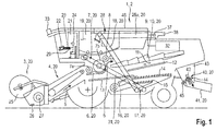
- a combine harvester 2 running agricultural harvester 1 takes in its front area on an attachment such as grain cutting unit 3, which is connected in a conventional manner with the inclined conveyor 4 of the combine harvester 2.
- the crop conveyor stream passing through the inclined conveyor 4, which is indicated by the arrow 5, is transferred in the upper-side, rearward region of the inclined conveyor 4 to the threshing elements 7 of the combine harvester 2, which are at least partly covered by a so-called concave 6 at the bottom.
- the threshing members 7 comprise a pre-accelerating drum 7a and a threshing drum 7b.
- a downstream of the threshing 7 supply drum 8 directs the rear in the region of the threshing 7 emerging from these crop flow 5 so that it is passed directly to a designed as Horden presentler 9 separator 10.
- the crop stream 5 is conveyed on the oscillating tray shaker 9 in such a way that free-moving grains 11 contained in the crop stream 5 are deposited in the bottom area of the tray shaker 9.
- the separating device 10 can also be designed as at least one Axialabscheiderotor.
- Both the concave 6 and the tray shaker 9 deposited grains 11 are fed via return bottom 12 and feed bottom 13 of a plurality of screen levels 14, 15 and a blower 16 existing cleaning device 17.
- the purified grain stream is finally transferred by an elevator 18 to a storage tank designed as a grain tank 19.
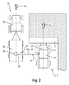
- the crop material contained in the grain tank 19 is transferred by means of a grain tank emptying device 28, which comprises a grain tank outlet pipe 28a and drive means, to a transport vehicle 34 accompanying the combine harvester 2, as in FIG Fig. 2 shown.
- the grain tank outlet pipe 28a has a sensor device 37 at its free end 38.
- the screen levels 14, 15 are partially arranged one above the other, so that the crop is screened in different degrees finely in two stages, wherein the mesh size of the screen planes 14, 15 is variable.
- the mesh size and / or the speed of the fan 16 By changing the mesh size and / or the speed of the fan 16, the proportion and the composition of the Erntegutmenge that passes through the sieve openings, the so-called sieve passage, and the proportion of transported over the Siebebenen 14, 15, the so called sieve overflow, influence.
- the upper screen plane 14 is usually designed so that it has in its rear region, the so-called tailings area, a larger mesh sizes.
- a sieve passage which passes through the upper sieve level 14 in the tailings area and a sieve overflow at the end of the lower sieve level 15 usually contains heavier particles, that is to say unrestrained ears.
- the sieve passage together with the sieve overflow is hereinafter referred to as so-called fürerieerntegutmenge.
- the fürerieerntegutmenge falls on an inclined collecting tray 30 below the cleaning device 17 and slides in a ear conveyor screw.
- the ear conveyor advances the Mathschreiberntegutmenge in a tailings elevator 31, through which they are again supplied to the threshing 7.
- the chopping device 40 has inter alia a rotating chopper drum 42, which is mounted in a chopper housing 43.
- the chopper drum 42 is occupied with movable knives 44, which mesh with fixed in the chopper housing 43 counter knives 45. With these knives 44 and the counter knives 45, the straw is shredded to shredded material and accelerated.
- the material flow emerging from the chopping device 40 consisting essentially of chopped straw and chaff, is conveyed on to the distributing device 41, which distributes the material flow in the field.
- the grain cutter 3, the feeder 4, the threshing 7, 7a, 7b and their associated concave 6, the feed drum 8, the separator 10, the cleaning device 17, the elevator 18, the tailings elevator 31, the Chopping device 40, the distribution device 41, the grain tank emptying device 28 and the grain tank outlet pipe 28 a generally referred to as working members 20 of the agricultural harvester 1.
- the required drive power of the working members 20 is provided by a motor 32 designed as an internal combustion engine, and transmitted by means of belt drive or the like to the respective working member 20.
- the agricultural harvester 1 which can be a forage harvester, in deviation from the combine harvester 2 shown here, has a vehicle cab 21.
- at least one control device 23 is provided with a display device 22 and an input device 29, by means of which, automatic or manually initiated by an operator 24 of the agricultural machine 1, a variety of processes for operating the harvester 1 can be controlled or regulated.
- the control device 23 is set up to receive and evaluate signals from sensors or the sensor device 37. On the basis of this evaluation, the control device 23 can, among other things, control or regulate the working members 20.
- the control device 23 communicates bidirectionally by means of a in Fig.
- bus system 46 with the various working organs 20 of the harvester 1 and its intended for the drive and the setting actuators, as well as the drive 32.
- an optical sensor device 33 is arranged, which, as well as the sensor device 37 on Grain tank outlet pipe 28a, is connected by the bus system 46 each with the control device 23.
- the grain cutting unit 3 comprises, inter alia, a reel 25, a knife bar 26 and a feed screw conveyor 27, as in FIG Fig. 1 indicated.
- Fig. 2 a schematic plan view of an agricultural harvester 1 and accompanying this transport vehicle 34 shown during a transfer process.
- the transport vehicle 34 may be, for example, a truck or, as shown here, a tractor 35 with a trailer 36.
- the grain tank outlet pipe 28a is pivoted by a pivot angle ⁇ from a rest or transport position to an operating position.
- Indicated at 39 is an impact point of the crop on the trailer 36.
- the impact point 39 travels during the loading in the longitudinal direction of the trailer 36 in order to achieve a uniform and complete filling.
- the driving speed V T of the tractor or the driving speed V E of the harvesting machine 1 can be temporarily varied.
- the harvesting machine 1 and the transport vehicle 34 travel at the same driving speed V E or V T in order to be able to continue the harvesting process during the transfer process.
- Overloading during the continuation of the harvesting process serves to increase the productivity of the harvesting machine 1 or the combine harvester 2.
- FIG. 3 shows a flowchart according to which the control and monitoring of the transfer process from the harvester 1 and the combine harvester 2 to the transport vehicle 34 is performed.
- step S1 the process of monitoring the overcharging during the parallel running harvesting process.
- the control device 23 monitors the operating situation of the harvester 1 or of the combine harvester 2, inter alia during the transfer process.
- the operating situation of the combine harvester 2 is influenced by various internal and external parameters.
- One of these parameters is an intervention of the operator 24 in the driving operation by abruptly accelerating or decelerating the harvester 1 or the combine harvester 2, whereby the travel speeds V E or V T of the combine harvester 2 and the transport vehicle 34 change relative to each other. This change would have a spatial offset between the moving at an unchanged vehicle speed V T transport vehicle 34 and the combine harvester 2 result. Accordingly, crop could be passed behind or in front of the transport vehicle 34, so that it falls at least partially on the ground.
- Another parameter represents an exceptional driving situation, resulting for example from a detection of an obstacle in front of the harvester 1 and / or the transport vehicle 34.
- a different evasive movement may be required, which leads to a lateral spacing.
- the lateral spacing due to an opposing deflection movement may result in a spacing exceeding the maximum lateral distance between the harvester 1 and the transport vehicle 34 within which lossless overloading is possible.
- the achievement of the maximum fill level of the transport vehicle 34 is also a parameter that influences the operating situation of the combine harvester 2. With the attainment of the maximum fill level, further transfer of crop to the transport vehicle 34 is no longer possible without loss.
- compliance with quality specifications for the result of the machining process by the combine harvester 2 represents another parameter that influences the operating situation. Since the transfer process takes up a not inconsiderable proportion of the available drive power of the combine harvester 2, this proportion of drive power can not be provided in operating situations of the combine harvester 2 in which, for example, the threshing elements 7, 7a, 7b temporarily retain a higher power consumption in order to maintain the quality of the discharge become.
- step S2 the presence of operator intervention is monitored.
- the manual intervention of an operator in the transfer process understood, for example in the form of a manual acceleration or deceleration of the combine harvester 1 or a controlled by the operator pivoting the grain tank outlet pipe 28a.
- a step S3 the presence of an overload situation is checked, for example caused by an increased intake of the crop quantity to be processed.
- a rotational speed sensor by means of a rotational speed sensor, a decrease in the input rotational speed of a work organ separating the crop is detected and forwarded to the control device 23 as a rotational speed signal.
- the control device 23 evaluates the speed signal based on a target-actual comparison of the current speed of each working member 20 to decide whether an overload situation of the working member 20 is present. In this case, the desired rotational speeds vary between the various working bodies 20. If an overload situation is detected, the transfer process is interrupted.
- the drive power of the grain tank emptying device 28, which is released as a result of the interruption of the transfer process, is automatically made available to the other working elements by the control device 23 in order to at least reduce the overload situation.
- the assignment of the released drive power is targeted by the controller 23 to the one or more work organs, which are in an overload situation.
- a further step S4 the presence of an unusual driving situation is checked.
- the presence of an obstacle in the apron of the harvester 1 and / or the transport vehicle 34 is detected.
- the occurrence of an obstacle can lead to a non-uniform evasive movement of harvester 1 and transport vehicle 34.
- the non-uniform evasive movement can be initiated by the respective operator of harvester 1 and transport vehicle 34.
- the transfer process is automatically interrupted by the control device 23. Accordingly, a steering movement of at least the harvesting machine 1 can be sensed and forwarded as a steering signal to the control device 23 for evaluation.
- the control device 23 determines on the basis of the steering signal a deviation from the substantially mutually parallel lanes of the harvester 1 and the transport vehicle 34. A resulting Unterbezieh way exceeding the required for the lossless overcharging leads to an interruption of the transfer process, by the control device 23 according to FIG initiated in step S7.
- a step S5 it is checked whether an overloading on the transport vehicle 34 is possible. Under the criterion of whether an overloading is possible, in addition to the level monitoring of the transport vehicle 34 also determines the presence of the transport vehicle 34 and its spacing to the harvester 1. In all cases, the transport vehicle 34 is not present, which is necessary for the overcharge distance is not achieved or is not met or the transport vehicle 34 is completely filled, the criterion that overcharging is not or no longer possible fulfilled. The monitoring of the level of the transport vehicle 34 and the trailer 36 and the presence of the transport vehicle 34 and its spacing to the harvester 1 is performed by the sensor device 37.
- the sensor device 37 is adapted to the presence of the transport vehicle 34, the distance of the transport vehicle 34 or to generate the respective level of the transport vehicle 34 and the trailer 36 signal representative. When the maximum fill level is reached, the transfer process is interrupted as well as when the absence of the transport vehicle 34 is detected.
- step S6 the occurrence of a critical process condition is monitored.
- a critical process state is characterized in that a different working member 20 than the grain tank emptying device 28 assumes an operating state in which the work result or the performance does not correspond to the intended.
- the distribution pattern of the crop material discharged from the shredded material distribution device designed as a radial distributor is not uniform on the ground or the distribution does not reach the desired distribution width, which corresponds to a critical process state.
- the situation may occur that as a result of operating the drive 32 at engine dimming, that is, in the limit load operation, and simultaneously retrieve additional power reserves, the operating behavior of the drive 32 assumes a critical state, which can lead to dying of the drive 32.
- the control line 23 releases the drive line released by the interruption of the transfer process to at least one operating element 20 if this is in a critical process state in order to eliminate it by this supporting measure.
Landscapes
- Life Sciences & Earth Sciences (AREA)
- Environmental Sciences (AREA)
- Harvester Elements (AREA)
- Combines (AREA)
Applications Claiming Priority (1)
| Application Number | Priority Date | Filing Date | Title |
|---|---|---|---|
| DE102014113001.4A DE102014113001A1 (de) | 2014-09-10 | 2014-09-10 | Verfahren zur Steuerung eines Überladeprozesses |
Publications (3)
| Publication Number | Publication Date |
|---|---|
| EP2995191A1 true EP2995191A1 (fr) | 2016-03-16 |
| EP2995191B1 EP2995191B1 (fr) | 2017-10-11 |
| EP2995191B2 EP2995191B2 (fr) | 2020-10-07 |
Family
ID=53433087
Family Applications (1)
| Application Number | Title | Priority Date | Filing Date |
|---|---|---|---|
| EP15172267.5A Active EP2995191B2 (fr) | 2014-09-10 | 2015-06-16 | Procédé de commande d'un processus de transbordement |
Country Status (4)
| Country | Link |
|---|---|
| EP (1) | EP2995191B2 (fr) |
| DE (1) | DE102014113001A1 (fr) |
| RU (1) | RU2683040C2 (fr) |
| UA (1) | UA120347C2 (fr) |
Cited By (12)
| Publication number | Priority date | Publication date | Assignee | Title |
|---|---|---|---|---|
| CN105850349A (zh) * | 2016-04-21 | 2016-08-17 | 广东丹霞农机有限公司 | 多功能智能化履带收割机 |
| WO2018228712A1 (fr) * | 2017-06-16 | 2018-12-20 | Fliegl Agrartechnik Gmbh | Dispositif de transbordement servant à ramasser et à transférer des produits de récolte sur un chariot de transport |
| CN112141553A (zh) * | 2020-09-09 | 2020-12-29 | 广东博智林机器人有限公司 | 储料装置、运料设备及运料设备的控制方法 |
| EP3760027A1 (fr) * | 2019-05-10 | 2021-01-06 | Deere & Company | Système d'entraînement pour une machine de récolte |
| EP4371394A2 (fr) | 2022-10-27 | 2024-05-22 | Deere & Company | Arrêt automatique de système de déchargement pour une opération de déchargement |
| US12402563B2 (en) | 2022-10-27 | 2025-09-02 | Deere & Company | Cross member location and avoidance during an unloading operation |
| US12490678B2 (en) | 2022-10-27 | 2025-12-09 | Deere & Company | Vehicle location with dynamic model and unloading control system |
| US12495734B2 (en) | 2022-10-27 | 2025-12-16 | Deere & Company | Three dimensional grid map for cross member location and avoidance during an unloading operation |
| US12504763B2 (en) | 2022-10-27 | 2025-12-23 | Deere & Company | Nudge proximity indication during control of an unloading operation |
| US12543655B2 (en) | 2022-10-27 | 2026-02-10 | Deere & Company | Controlling transfer of material from a transfer vehicle to a haulage vehicle based on an internal profile of the haulage vehicle |
| US12550826B2 (en) | 2022-10-27 | 2026-02-17 | Deere & Company | Vehicle parameter offset value management and control system |
| US12588593B2 (en) | 2022-10-27 | 2026-03-31 | Deere & Company | Fill profile and tracking control during an unloading operation based on a CAD file |
Families Citing this family (62)
| Publication number | Priority date | Publication date | Assignee | Title |
|---|---|---|---|---|
| US11079725B2 (en) | 2019-04-10 | 2021-08-03 | Deere & Company | Machine control using real-time model |
| US11653588B2 (en) | 2018-10-26 | 2023-05-23 | Deere & Company | Yield map generation and control system |
| US11672203B2 (en) | 2018-10-26 | 2023-06-13 | Deere & Company | Predictive map generation and control |
| US11589509B2 (en) | 2018-10-26 | 2023-02-28 | Deere & Company | Predictive machine characteristic map generation and control system |
| US11641800B2 (en) | 2020-02-06 | 2023-05-09 | Deere & Company | Agricultural harvesting machine with pre-emergence weed detection and mitigation system |
| US11467605B2 (en) | 2019-04-10 | 2022-10-11 | Deere & Company | Zonal machine control |
| US11957072B2 (en) | 2020-02-06 | 2024-04-16 | Deere & Company | Pre-emergence weed detection and mitigation system |
| US11178818B2 (en) | 2018-10-26 | 2021-11-23 | Deere & Company | Harvesting machine control system with fill level processing based on yield data |
| US12069978B2 (en) | 2018-10-26 | 2024-08-27 | Deere & Company | Predictive environmental characteristic map generation and control system |
| US11240961B2 (en) | 2018-10-26 | 2022-02-08 | Deere & Company | Controlling a harvesting machine based on a geo-spatial representation indicating where the harvesting machine is likely to reach capacity |
| US11234366B2 (en) | 2019-04-10 | 2022-02-01 | Deere & Company | Image selection for machine control |
| US11778945B2 (en) | 2019-04-10 | 2023-10-10 | Deere & Company | Machine control using real-time model |
| US12035648B2 (en) | 2020-02-06 | 2024-07-16 | Deere & Company | Predictive weed map generation and control system |
| US12329148B2 (en) | 2020-02-06 | 2025-06-17 | Deere & Company | Predictive weed map and material application machine control |
| US12225846B2 (en) | 2020-02-06 | 2025-02-18 | Deere & Company | Machine control using a predictive map |
| US11477940B2 (en) | 2020-03-26 | 2022-10-25 | Deere & Company | Mobile work machine control based on zone parameter modification |
| US12013245B2 (en) | 2020-10-09 | 2024-06-18 | Deere & Company | Predictive map generation and control system |
| US11927459B2 (en) | 2020-10-09 | 2024-03-12 | Deere & Company | Machine control using a predictive map |
| US11675354B2 (en) | 2020-10-09 | 2023-06-13 | Deere & Company | Machine control using a predictive map |
| US11650587B2 (en) | 2020-10-09 | 2023-05-16 | Deere & Company | Predictive power map generation and control system |
| US12386354B2 (en) | 2020-10-09 | 2025-08-12 | Deere & Company | Predictive power map generation and control system |
| US11844311B2 (en) | 2020-10-09 | 2023-12-19 | Deere & Company | Machine control using a predictive map |
| US11874669B2 (en) | 2020-10-09 | 2024-01-16 | Deere & Company | Map generation and control system |
| US11474523B2 (en) | 2020-10-09 | 2022-10-18 | Deere & Company | Machine control using a predictive speed map |
| US11635765B2 (en) | 2020-10-09 | 2023-04-25 | Deere & Company | Crop state map generation and control system |
| US12550802B2 (en) | 2020-10-08 | 2026-02-17 | Deere & Company | Predictive machine characteristic map generation and control system |
| US11727680B2 (en) | 2020-10-09 | 2023-08-15 | Deere & Company | Predictive map generation based on seeding characteristics and control |
| US11825768B2 (en) | 2020-10-09 | 2023-11-28 | Deere & Company | Machine control using a predictive map |
| US11849672B2 (en) | 2020-10-09 | 2023-12-26 | Deere & Company | Machine control using a predictive map |
| US11895948B2 (en) | 2020-10-09 | 2024-02-13 | Deere & Company | Predictive map generation and control based on soil properties |
| US11864483B2 (en) | 2020-10-09 | 2024-01-09 | Deere & Company | Predictive map generation and control system |
| US12422847B2 (en) | 2020-10-09 | 2025-09-23 | Deere & Company | Predictive agricultural model and map generation |
| US12419220B2 (en) | 2020-10-09 | 2025-09-23 | Deere & Company | Predictive map generation and control system |
| US11889788B2 (en) | 2020-10-09 | 2024-02-06 | Deere & Company | Predictive biomass map generation and control |
| US11711995B2 (en) | 2020-10-09 | 2023-08-01 | Deere & Company | Machine control using a predictive map |
| US11983009B2 (en) | 2020-10-09 | 2024-05-14 | Deere & Company | Map generation and control system |
| US11592822B2 (en) | 2020-10-09 | 2023-02-28 | Deere & Company | Machine control using a predictive map |
| US11946747B2 (en) | 2020-10-09 | 2024-04-02 | Deere & Company | Crop constituent map generation and control system |
| US12178158B2 (en) | 2020-10-09 | 2024-12-31 | Deere & Company | Predictive map generation and control system for an agricultural work machine |
| US12069986B2 (en) | 2020-10-09 | 2024-08-27 | Deere & Company | Map generation and control system |
| US11871697B2 (en) | 2020-10-09 | 2024-01-16 | Deere & Company | Crop moisture map generation and control system |
| US11849671B2 (en) | 2020-10-09 | 2023-12-26 | Deere & Company | Crop state map generation and control system |
| US11845449B2 (en) | 2020-10-09 | 2023-12-19 | Deere & Company | Map generation and control system |
| US12250905B2 (en) | 2020-10-09 | 2025-03-18 | Deere & Company | Machine control using a predictive map |
| US11889787B2 (en) | 2020-10-09 | 2024-02-06 | Deere & Company | Predictive speed map generation and control system |
| US12127500B2 (en) | 2021-01-27 | 2024-10-29 | Deere & Company | Machine control using a map with regime zones |
| US12229886B2 (en) | 2021-10-01 | 2025-02-18 | Deere & Company | Historical crop state model, predictive crop state map generation and control system |
| US12310286B2 (en) | 2021-12-14 | 2025-05-27 | Deere & Company | Crop constituent sensing |
| US12302791B2 (en) | 2021-12-20 | 2025-05-20 | Deere & Company | Crop constituents, predictive mapping, and agricultural harvester control |
| US12245549B2 (en) | 2022-01-11 | 2025-03-11 | Deere & Company | Predictive response map generation and control system |
| US12520759B2 (en) | 2022-01-26 | 2026-01-13 | Deere & Company | Systems and methods for predicting material dynamics |
| US12082531B2 (en) | 2022-01-26 | 2024-09-10 | Deere & Company | Systems and methods for predicting material dynamics |
| US12295288B2 (en) | 2022-04-05 | 2025-05-13 | Deere &Company | Predictive machine setting map generation and control system |
| US12284934B2 (en) | 2022-04-08 | 2025-04-29 | Deere & Company | Systems and methods for predictive tractive characteristics and control |
| US12298767B2 (en) | 2022-04-08 | 2025-05-13 | Deere & Company | Predictive material consumption map and control |
| US12358493B2 (en) | 2022-04-08 | 2025-07-15 | Deere & Company | Systems and methods for predictive power requirements and control |
| US12058951B2 (en) | 2022-04-08 | 2024-08-13 | Deere & Company | Predictive nutrient map and control |
| US12582035B2 (en) | 2022-04-08 | 2026-03-24 | Deere & Company | Systems and methods for predictive power requirements and control |
| US12604791B2 (en) | 2022-07-06 | 2026-04-21 | Deere & Company | Machine control based upon estimated operator skill level trend |
| AU2022473991A1 (en) | 2022-08-11 | 2024-11-14 | Deere & Company | Systems and methods for predictive harvesting logistics |
| EP4568467A4 (fr) | 2022-08-11 | 2026-05-06 | Deere & Co | Systèmes et procédés de logistique de récolte prédictive |
| CN117461476B (zh) * | 2023-12-07 | 2025-10-17 | 舒城县农业科学研究所 | 一种绿色水稻种植用秸秆处理装置 |
Citations (7)
| Publication number | Priority date | Publication date | Assignee | Title |
|---|---|---|---|---|
| WO1998046065A1 (fr) * | 1997-04-16 | 1998-10-22 | Carnegie Mellon University | Machine agricole de recolte commandee par robot |
| US5855108A (en) * | 1996-02-16 | 1999-01-05 | Case Corporation | Alarm monitor for belt slip in a combine |
| EP1731983A1 (fr) * | 2005-06-02 | 2006-12-13 | Deere & Company | Machine de travail agricole pourvue d'un dispositif de déversement et d'un capteur de collision |
| WO2012110544A1 (fr) * | 2011-02-18 | 2012-08-23 | Cnh Belgium N.V. | Système et procédé de commande d'une goulotte de moissonneuse |
| WO2013096593A1 (fr) | 2011-12-20 | 2013-06-27 | Agco Corporation | Commande de vis de déchargement |
| EP2702854A1 (fr) * | 2012-07-03 | 2014-03-05 | CLAAS Selbstfahrende Erntemaschinen GmbH | Machine agricole automobile |
| US20140224377A1 (en) * | 2013-02-08 | 2014-08-14 | Deere & Company | Method and stereo vision system for facilitating the unloading of agricultural material from a vehicle |
Family Cites Families (5)
| Publication number | Priority date | Publication date | Assignee | Title |
|---|---|---|---|---|
| DE102004052298A1 (de) * | 2004-10-06 | 2006-06-08 | Claas Selbstfahrende Erntemaschinen Gmbh | Überladeassistenzsystem |
| DE102009027245A1 (de) | 2009-06-26 | 2010-12-30 | Deere & Company, Moline | Steueranordnung zur Kontrolle des Überladens landwirtschaftlichen Ernteguts von einer Erntemaschine auf ein Transportfahrzeug |
| DE102010043854B4 (de) | 2010-11-12 | 2016-01-14 | Deere & Company | Steueranordnung zur Kontrolle des Überladens landwirtschaftlichen Ernteguts von einer Erntemaschine auf ein Transportfahrzeug |
| DE102011050629A1 (de) | 2011-05-25 | 2012-11-29 | Claas Selbstfahrende Erntemaschinen Gmbh | Erntevorrichtung |
| DE102012211001A1 (de) | 2012-06-27 | 2014-01-02 | Deere & Company | Anordnung zur Kontrolle einer Austrageinrichtung einer Erntemaschine mit einer selbsttätigen Positionierung in einer Ruhestellung bei nicht möglichen bzw. stattfindendem Überladevorgang |
-
2014
- 2014-09-10 DE DE102014113001.4A patent/DE102014113001A1/de not_active Ceased
-
2015
- 2015-06-16 EP EP15172267.5A patent/EP2995191B2/fr active Active
- 2015-09-07 RU RU2015137963A patent/RU2683040C2/ru active
- 2015-09-08 UA UAA201508691A patent/UA120347C2/uk unknown
Patent Citations (7)
| Publication number | Priority date | Publication date | Assignee | Title |
|---|---|---|---|---|
| US5855108A (en) * | 1996-02-16 | 1999-01-05 | Case Corporation | Alarm monitor for belt slip in a combine |
| WO1998046065A1 (fr) * | 1997-04-16 | 1998-10-22 | Carnegie Mellon University | Machine agricole de recolte commandee par robot |
| EP1731983A1 (fr) * | 2005-06-02 | 2006-12-13 | Deere & Company | Machine de travail agricole pourvue d'un dispositif de déversement et d'un capteur de collision |
| WO2012110544A1 (fr) * | 2011-02-18 | 2012-08-23 | Cnh Belgium N.V. | Système et procédé de commande d'une goulotte de moissonneuse |
| WO2013096593A1 (fr) | 2011-12-20 | 2013-06-27 | Agco Corporation | Commande de vis de déchargement |
| EP2702854A1 (fr) * | 2012-07-03 | 2014-03-05 | CLAAS Selbstfahrende Erntemaschinen GmbH | Machine agricole automobile |
| US20140224377A1 (en) * | 2013-02-08 | 2014-08-14 | Deere & Company | Method and stereo vision system for facilitating the unloading of agricultural material from a vehicle |
Cited By (15)
| Publication number | Priority date | Publication date | Assignee | Title |
|---|---|---|---|---|
| CN105850349A (zh) * | 2016-04-21 | 2016-08-17 | 广东丹霞农机有限公司 | 多功能智能化履带收割机 |
| WO2018228712A1 (fr) * | 2017-06-16 | 2018-12-20 | Fliegl Agrartechnik Gmbh | Dispositif de transbordement servant à ramasser et à transférer des produits de récolte sur un chariot de transport |
| CN110913685A (zh) * | 2017-06-16 | 2020-03-24 | 弗雷格尔农业技术有限公司 | 用于收集收获的物料并转移到运输车辆的负载转移装置 |
| US11612102B2 (en) | 2019-05-10 | 2023-03-28 | Deere & Company | Drive system for a harvester |
| EP3760027A1 (fr) * | 2019-05-10 | 2021-01-06 | Deere & Company | Système d'entraînement pour une machine de récolte |
| CN112141553A (zh) * | 2020-09-09 | 2020-12-29 | 广东博智林机器人有限公司 | 储料装置、运料设备及运料设备的控制方法 |
| CN112141553B (zh) * | 2020-09-09 | 2022-06-03 | 广东博智林机器人有限公司 | 储料装置、运料设备及运料设备的控制方法 |
| EP4371394A2 (fr) | 2022-10-27 | 2024-05-22 | Deere & Company | Arrêt automatique de système de déchargement pour une opération de déchargement |
| US12402563B2 (en) | 2022-10-27 | 2025-09-02 | Deere & Company | Cross member location and avoidance during an unloading operation |
| US12490678B2 (en) | 2022-10-27 | 2025-12-09 | Deere & Company | Vehicle location with dynamic model and unloading control system |
| US12495734B2 (en) | 2022-10-27 | 2025-12-16 | Deere & Company | Three dimensional grid map for cross member location and avoidance during an unloading operation |
| US12504763B2 (en) | 2022-10-27 | 2025-12-23 | Deere & Company | Nudge proximity indication during control of an unloading operation |
| US12543655B2 (en) | 2022-10-27 | 2026-02-10 | Deere & Company | Controlling transfer of material from a transfer vehicle to a haulage vehicle based on an internal profile of the haulage vehicle |
| US12550826B2 (en) | 2022-10-27 | 2026-02-17 | Deere & Company | Vehicle parameter offset value management and control system |
| US12588593B2 (en) | 2022-10-27 | 2026-03-31 | Deere & Company | Fill profile and tracking control during an unloading operation based on a CAD file |
Also Published As
| Publication number | Publication date |
|---|---|
| EP2995191B2 (fr) | 2020-10-07 |
| DE102014113001A1 (de) | 2016-03-10 |
| RU2683040C2 (ru) | 2019-03-26 |
| UA120347C2 (uk) | 2019-11-25 |
| RU2015137963A3 (fr) | 2018-09-07 |
| EP2995191B1 (fr) | 2017-10-11 |
| RU2015137963A (ru) | 2017-03-14 |
Similar Documents
| Publication | Publication Date | Title |
|---|---|---|
| EP2995191B1 (fr) | Procédé de commande d'un processus de transbordement | |
| EP3662741B2 (fr) | Machine de travail agricole ainsi que procédé de fonctionnement d'une machine de travail agricole | |
| EP2829171B1 (fr) | Moissonneuse automotrice et véhicule associé | |
| EP3533315B2 (fr) | Récolteuse-hacheuse-chargeuse de fourrage et procédé de fonctionnement d'une récolteuse-hacheuse-chargeuse de fourrage | |
| EP3000307B1 (fr) | Procede de transbordement pour des moissonneuses | |
| EP2510775B1 (fr) | Système et procédé de commande du transfert de récoltes | |
| EP2526752B1 (fr) | Dispositif de récolte | |
| EP1731017B1 (fr) | Méthode de commande d'une moissoneuse | |
| EP1493318B1 (fr) | Procédé de control d'un ensemble de battage pour moissonneuse-batteuse | |
| EP1306536A1 (fr) | Système de commande de puissance de sortie d'un moteur | |
| DE102015202643A1 (de) | Erntegutrestesensorsystem für einen Erntegutresteverteiler | |
| EP3597027B1 (fr) | Moissonneuse-batteuse doté d'un convoyeur incliné pourvu de rouleau de déviation inférieur réglable | |
| EP3494771A1 (fr) | Dispositif de hauteur de coupe automatique | |
| EP0349908B1 (fr) | Dispositif transporteur pour une moissonneuse | |
| EP3530101A1 (fr) | Récolteuse-hacheuse-chargeuse de fourrage automotrice | |
| EP2377385B1 (fr) | Procédé d'établissement d'un amoncellement de récolte se développant sur un organe de travail d'une moissonneuse automobile et dispositif de commande | |
| EP1856966A1 (fr) | Procédé et dispositif destiné au fonctionnement d'un dispositif de broyage et de répartition d'épinards | |
| EP4218394A1 (fr) | Ramasseuse-hacheuse automotrice et procédé de fonctionnement d'une ramasseuse-hacheuse automotrice | |
| EP3300581B1 (fr) | Ensileuse comprenant un canal de traitement de récolte et une barre de mesure destinée à détecter une distribution transversale de la récolte dans le canal de traitement de récolte | |
| EP3967127B1 (fr) | Récolteuse-hacheuse-chargeuse de fourrage automotrice | |
| EP4074160B1 (fr) | Procédé de réglage d'un niveau de remplissage dans un récipient | |
| DE102023129476A1 (de) | Management der leistungsumschaltung für fahrerassistenz | |
| EP4154697B1 (fr) | Système d'aide à la conduite d'un engin d'abattage-façonnage pourvu de mécanisme de coupe de bande | |
| EP2110013B1 (fr) | Machine agricole dotée d'une fonction d'urgence | |
| EP2108248B1 (fr) | Ramasseuse-hacheuse et dispositif d'introduction pour une ramasseuse-hacheuse |
Legal Events
| Date | Code | Title | Description |
|---|---|---|---|
| PUAI | Public reference made under article 153(3) epc to a published international application that has entered the european phase |
Free format text: ORIGINAL CODE: 0009012 |
|
| AK | Designated contracting states |
Kind code of ref document: A1 Designated state(s): AL AT BE BG CH CY CZ DE DK EE ES FI FR GB GR HR HU IE IS IT LI LT LU LV MC MK MT NL NO PL PT RO RS SE SI SK SM TR |
|
| AX | Request for extension of the european patent |
Extension state: BA ME |
|
| 17P | Request for examination filed |
Effective date: 20160916 |
|
| RBV | Designated contracting states (corrected) |
Designated state(s): AL AT BE BG CH CY CZ DE DK EE ES FI FR GB GR HR HU IE IS IT LI LT LU LV MC MK MT NL NO PL PT RO RS SE SI SK SM TR |
|
| RAP1 | Party data changed (applicant data changed or rights of an application transferred) |
Owner name: CLAAS SELBSTFAHRENDE ERNTEMASCHINEN GMBH |
|
| GRAP | Despatch of communication of intention to grant a patent |
Free format text: ORIGINAL CODE: EPIDOSNIGR1 |
|
| STAA | Information on the status of an ep patent application or granted ep patent |
Free format text: STATUS: GRANT OF PATENT IS INTENDED |
|
| INTG | Intention to grant announced |
Effective date: 20170627 |
|
| GRAS | Grant fee paid |
Free format text: ORIGINAL CODE: EPIDOSNIGR3 |
|
| GRAA | (expected) grant |
Free format text: ORIGINAL CODE: 0009210 |
|
| STAA | Information on the status of an ep patent application or granted ep patent |
Free format text: STATUS: THE PATENT HAS BEEN GRANTED |
|
| AK | Designated contracting states |
Kind code of ref document: B1 Designated state(s): AL AT BE BG CH CY CZ DE DK EE ES FI FR GB GR HR HU IE IS IT LI LT LU LV MC MK MT NL NO PL PT RO RS SE SI SK SM TR |
|
| REG | Reference to a national code |
Ref country code: GB Ref legal event code: FG4D Free format text: NOT ENGLISH |
|
| REG | Reference to a national code |
Ref country code: CH Ref legal event code: EP |
|
| REG | Reference to a national code |
Ref country code: IE Ref legal event code: FG4D Free format text: LANGUAGE OF EP DOCUMENT: GERMAN |
|
| REG | Reference to a national code |
Ref country code: AT Ref legal event code: REF Ref document number: 935197 Country of ref document: AT Kind code of ref document: T Effective date: 20171115 |
|
| REG | Reference to a national code |
Ref country code: DE Ref legal event code: R096 Ref document number: 502015002052 Country of ref document: DE |
|
| REG | Reference to a national code |
Ref country code: NL Ref legal event code: MP Effective date: 20171011 |
|
| REG | Reference to a national code |
Ref country code: LT Ref legal event code: MG4D |
|
| PG25 | Lapsed in a contracting state [announced via postgrant information from national office to epo] |
Ref country code: NL Free format text: LAPSE BECAUSE OF FAILURE TO SUBMIT A TRANSLATION OF THE DESCRIPTION OR TO PAY THE FEE WITHIN THE PRESCRIBED TIME-LIMIT Effective date: 20171011 |
|
| PG25 | Lapsed in a contracting state [announced via postgrant information from national office to epo] |
Ref country code: LT Free format text: LAPSE BECAUSE OF FAILURE TO SUBMIT A TRANSLATION OF THE DESCRIPTION OR TO PAY THE FEE WITHIN THE PRESCRIBED TIME-LIMIT Effective date: 20171011 Ref country code: FI Free format text: LAPSE BECAUSE OF FAILURE TO SUBMIT A TRANSLATION OF THE DESCRIPTION OR TO PAY THE FEE WITHIN THE PRESCRIBED TIME-LIMIT Effective date: 20171011 Ref country code: SE Free format text: LAPSE BECAUSE OF FAILURE TO SUBMIT A TRANSLATION OF THE DESCRIPTION OR TO PAY THE FEE WITHIN THE PRESCRIBED TIME-LIMIT Effective date: 20171011 Ref country code: ES Free format text: LAPSE BECAUSE OF FAILURE TO SUBMIT A TRANSLATION OF THE DESCRIPTION OR TO PAY THE FEE WITHIN THE PRESCRIBED TIME-LIMIT Effective date: 20171011 Ref country code: NO Free format text: LAPSE BECAUSE OF FAILURE TO SUBMIT A TRANSLATION OF THE DESCRIPTION OR TO PAY THE FEE WITHIN THE PRESCRIBED TIME-LIMIT Effective date: 20180111 |
|
| PG25 | Lapsed in a contracting state [announced via postgrant information from national office to epo] |
Ref country code: RS Free format text: LAPSE BECAUSE OF FAILURE TO SUBMIT A TRANSLATION OF THE DESCRIPTION OR TO PAY THE FEE WITHIN THE PRESCRIBED TIME-LIMIT Effective date: 20171011 Ref country code: BG Free format text: LAPSE BECAUSE OF FAILURE TO SUBMIT A TRANSLATION OF THE DESCRIPTION OR TO PAY THE FEE WITHIN THE PRESCRIBED TIME-LIMIT Effective date: 20180111 Ref country code: IS Free format text: LAPSE BECAUSE OF FAILURE TO SUBMIT A TRANSLATION OF THE DESCRIPTION OR TO PAY THE FEE WITHIN THE PRESCRIBED TIME-LIMIT Effective date: 20180211 Ref country code: GR Free format text: LAPSE BECAUSE OF FAILURE TO SUBMIT A TRANSLATION OF THE DESCRIPTION OR TO PAY THE FEE WITHIN THE PRESCRIBED TIME-LIMIT Effective date: 20180112 Ref country code: LV Free format text: LAPSE BECAUSE OF FAILURE TO SUBMIT A TRANSLATION OF THE DESCRIPTION OR TO PAY THE FEE WITHIN THE PRESCRIBED TIME-LIMIT Effective date: 20171011 Ref country code: HR Free format text: LAPSE BECAUSE OF FAILURE TO SUBMIT A TRANSLATION OF THE DESCRIPTION OR TO PAY THE FEE WITHIN THE PRESCRIBED TIME-LIMIT Effective date: 20171011 |
|
| REG | Reference to a national code |
Ref country code: FR Ref legal event code: PLFP Year of fee payment: 4 |
|
| REG | Reference to a national code |
Ref country code: DE Ref legal event code: R026 Ref document number: 502015002052 Country of ref document: DE |
|
| PLBI | Opposition filed |
Free format text: ORIGINAL CODE: 0009260 |
|
| PLAX | Notice of opposition and request to file observation + time limit sent |
Free format text: ORIGINAL CODE: EPIDOSNOBS2 |
|
| PG25 | Lapsed in a contracting state [announced via postgrant information from national office to epo] |
Ref country code: EE Free format text: LAPSE BECAUSE OF FAILURE TO SUBMIT A TRANSLATION OF THE DESCRIPTION OR TO PAY THE FEE WITHIN THE PRESCRIBED TIME-LIMIT Effective date: 20171011 Ref country code: CZ Free format text: LAPSE BECAUSE OF FAILURE TO SUBMIT A TRANSLATION OF THE DESCRIPTION OR TO PAY THE FEE WITHIN THE PRESCRIBED TIME-LIMIT Effective date: 20171011 Ref country code: SK Free format text: LAPSE BECAUSE OF FAILURE TO SUBMIT A TRANSLATION OF THE DESCRIPTION OR TO PAY THE FEE WITHIN THE PRESCRIBED TIME-LIMIT Effective date: 20171011 Ref country code: DK Free format text: LAPSE BECAUSE OF FAILURE TO SUBMIT A TRANSLATION OF THE DESCRIPTION OR TO PAY THE FEE WITHIN THE PRESCRIBED TIME-LIMIT Effective date: 20171011 |
|
| 26 | Opposition filed |
Opponent name: DEERE & COMPANY/JOHN DEERE GMBH & CO. KG Effective date: 20180710 |
|
| PG25 | Lapsed in a contracting state [announced via postgrant information from national office to epo] |
Ref country code: PL Free format text: LAPSE BECAUSE OF FAILURE TO SUBMIT A TRANSLATION OF THE DESCRIPTION OR TO PAY THE FEE WITHIN THE PRESCRIBED TIME-LIMIT Effective date: 20171011 Ref country code: RO Free format text: LAPSE BECAUSE OF FAILURE TO SUBMIT A TRANSLATION OF THE DESCRIPTION OR TO PAY THE FEE WITHIN THE PRESCRIBED TIME-LIMIT Effective date: 20171011 Ref country code: SM Free format text: LAPSE BECAUSE OF FAILURE TO SUBMIT A TRANSLATION OF THE DESCRIPTION OR TO PAY THE FEE WITHIN THE PRESCRIBED TIME-LIMIT Effective date: 20171011 |
|
| PG25 | Lapsed in a contracting state [announced via postgrant information from national office to epo] |
Ref country code: MT Free format text: LAPSE BECAUSE OF FAILURE TO SUBMIT A TRANSLATION OF THE DESCRIPTION OR TO PAY THE FEE WITHIN THE PRESCRIBED TIME-LIMIT Effective date: 20171011 |
|
| PLBB | Reply of patent proprietor to notice(s) of opposition received |
Free format text: ORIGINAL CODE: EPIDOSNOBS3 |
|
| PG25 | Lapsed in a contracting state [announced via postgrant information from national office to epo] |
Ref country code: SI Free format text: LAPSE BECAUSE OF FAILURE TO SUBMIT A TRANSLATION OF THE DESCRIPTION OR TO PAY THE FEE WITHIN THE PRESCRIBED TIME-LIMIT Effective date: 20171011 |
|
| REG | Reference to a national code |
Ref country code: CH Ref legal event code: PL |
|
| REG | Reference to a national code |
Ref country code: IE Ref legal event code: MM4A |
|
| PG25 | Lapsed in a contracting state [announced via postgrant information from national office to epo] |
Ref country code: MC Free format text: LAPSE BECAUSE OF FAILURE TO SUBMIT A TRANSLATION OF THE DESCRIPTION OR TO PAY THE FEE WITHIN THE PRESCRIBED TIME-LIMIT Effective date: 20171011 Ref country code: LU Free format text: LAPSE BECAUSE OF NON-PAYMENT OF DUE FEES Effective date: 20180616 |
|
| PG25 | Lapsed in a contracting state [announced via postgrant information from national office to epo] |
Ref country code: LI Free format text: LAPSE BECAUSE OF NON-PAYMENT OF DUE FEES Effective date: 20180630 Ref country code: IE Free format text: LAPSE BECAUSE OF NON-PAYMENT OF DUE FEES Effective date: 20180616 Ref country code: CH Free format text: LAPSE BECAUSE OF NON-PAYMENT OF DUE FEES Effective date: 20180630 |
|
| GBPC | Gb: european patent ceased through non-payment of renewal fee |
Effective date: 20190616 |
|
| PG25 | Lapsed in a contracting state [announced via postgrant information from national office to epo] |
Ref country code: TR Free format text: LAPSE BECAUSE OF FAILURE TO SUBMIT A TRANSLATION OF THE DESCRIPTION OR TO PAY THE FEE WITHIN THE PRESCRIBED TIME-LIMIT Effective date: 20171011 |
|
| PG25 | Lapsed in a contracting state [announced via postgrant information from national office to epo] |
Ref country code: GB Free format text: LAPSE BECAUSE OF NON-PAYMENT OF DUE FEES Effective date: 20190616 |
|
| PG25 | Lapsed in a contracting state [announced via postgrant information from national office to epo] |
Ref country code: PT Free format text: LAPSE BECAUSE OF FAILURE TO SUBMIT A TRANSLATION OF THE DESCRIPTION OR TO PAY THE FEE WITHIN THE PRESCRIBED TIME-LIMIT Effective date: 20171011 |
|
| PG25 | Lapsed in a contracting state [announced via postgrant information from national office to epo] |
Ref country code: CY Free format text: LAPSE BECAUSE OF FAILURE TO SUBMIT A TRANSLATION OF THE DESCRIPTION OR TO PAY THE FEE WITHIN THE PRESCRIBED TIME-LIMIT Effective date: 20171011 Ref country code: MK Free format text: LAPSE BECAUSE OF NON-PAYMENT OF DUE FEES Effective date: 20171011 Ref country code: HU Free format text: LAPSE BECAUSE OF FAILURE TO SUBMIT A TRANSLATION OF THE DESCRIPTION OR TO PAY THE FEE WITHIN THE PRESCRIBED TIME-LIMIT; INVALID AB INITIO Effective date: 20150616 |
|
| PG25 | Lapsed in a contracting state [announced via postgrant information from national office to epo] |
Ref country code: AL Free format text: LAPSE BECAUSE OF FAILURE TO SUBMIT A TRANSLATION OF THE DESCRIPTION OR TO PAY THE FEE WITHIN THE PRESCRIBED TIME-LIMIT Effective date: 20171011 |
|
| PUAH | Patent maintained in amended form |
Free format text: ORIGINAL CODE: 0009272 |
|
| STAA | Information on the status of an ep patent application or granted ep patent |
Free format text: STATUS: PATENT MAINTAINED AS AMENDED |
|
| 27A | Patent maintained in amended form |
Effective date: 20201007 |
|
| AK | Designated contracting states |
Kind code of ref document: B2 Designated state(s): AL AT BE BG CH CY CZ DE DK EE ES FI FR GB GR HR HU IE IS IT LI LT LU LV MC MK MT NL NO PL PT RO RS SE SI SK SM TR |
|
| REG | Reference to a national code |
Ref country code: DE Ref legal event code: R102 Ref document number: 502015002052 Country of ref document: DE |
|
| REG | Reference to a national code |
Ref country code: AT Ref legal event code: MM01 Ref document number: 935197 Country of ref document: AT Kind code of ref document: T Effective date: 20200616 |
|
| PG25 | Lapsed in a contracting state [announced via postgrant information from national office to epo] |
Ref country code: AT Free format text: LAPSE BECAUSE OF NON-PAYMENT OF DUE FEES Effective date: 20200616 |
|
| P01 | Opt-out of the competence of the unified patent court (upc) registered |
Effective date: 20230516 |
|
| PGFP | Annual fee paid to national office [announced via postgrant information from national office to epo] |
Ref country code: DE Payment date: 20250618 Year of fee payment: 11 |
|
| PGFP | Annual fee paid to national office [announced via postgrant information from national office to epo] |
Ref country code: BE Payment date: 20250618 Year of fee payment: 11 |
|
| PGFP | Annual fee paid to national office [announced via postgrant information from national office to epo] |
Ref country code: FR Payment date: 20250625 Year of fee payment: 11 |
|
| PGFP | Annual fee paid to national office [announced via postgrant information from national office to epo] |
Ref country code: IT Payment date: 20250624 Year of fee payment: 11 |