EP2995218B1 - Multidimensional applicator - Google Patents
Multidimensional applicator Download PDFInfo
- Publication number
- EP2995218B1 EP2995218B1 EP14197599.5A EP14197599A EP2995218B1 EP 2995218 B1 EP2995218 B1 EP 2995218B1 EP 14197599 A EP14197599 A EP 14197599A EP 2995218 B1 EP2995218 B1 EP 2995218B1
- Authority
- EP
- European Patent Office
- Prior art keywords
- applicator
- bristle tuft
- bristles
- ridge
- wedge
- Prior art date
- Legal status (The legal status is an assumption and is not a legal conclusion. Google has not performed a legal analysis and makes no representation as to the accuracy of the status listed.)
- Active
Links
Images




Classifications
-
- A—HUMAN NECESSITIES
- A46—BRUSHWARE
- A46B—BRUSHES
- A46B9/00—Arrangements of the bristles in the brush body
- A46B9/02—Position or arrangement of bristles in relation to surface of the brush body, e.g. inclined, in rows, in groups
- A46B9/021—Position or arrangement of bristles in relation to surface of the brush body, e.g. inclined, in rows, in groups arranged like in cosmetics brushes, e.g. mascara, nail polish, eye shadow
-
- A—HUMAN NECESSITIES
- A45—HAND OR TRAVELLING ARTICLES
- A45D—HAIRDRESSING OR SHAVING EQUIPMENT; EQUIPMENT FOR COSMETICS OR COSMETIC TREATMENTS, e.g. FOR MANICURING OR PEDICURING
- A45D40/00—Casings or accessories specially adapted for storing or handling solid or pasty toiletry or cosmetic substances, e.g. shaving soaps or lipsticks
- A45D40/26—Appliances specially adapted for applying pasty paint, e.g. using roller, using a ball
- A45D40/262—Appliances specially adapted for applying pasty paint, e.g. using roller, using a ball using a brush or the like
-
- A—HUMAN NECESSITIES
- A46—BRUSHWARE
- A46B—BRUSHES
- A46B9/00—Arrangements of the bristles in the brush body
- A46B9/02—Position or arrangement of bristles in relation to surface of the brush body, e.g. inclined, in rows, in groups
- A46B9/026—Position or arrangement of bristles in relation to surface of the brush body, e.g. inclined, in rows, in groups where the surface of the brush body or carrier is not in one plane, e.g. not flat
-
- A—HUMAN NECESSITIES
- A46—BRUSHWARE
- A46B—BRUSHES
- A46B9/00—Arrangements of the bristles in the brush body
- A46B9/02—Position or arrangement of bristles in relation to surface of the brush body, e.g. inclined, in rows, in groups
- A46B9/028—Bristle profile, the end of the bristle defining a surface other than a single plane or deviating from a simple geometric form, e.g. cylinder, sphere or cone
-
- A—HUMAN NECESSITIES
- A46—BRUSHWARE
- A46B—BRUSHES
- A46B2200/00—Brushes characterized by their functions, uses or applications
- A46B2200/10—For human or animal care
- A46B2200/1046—Brush used for applying cosmetics
Definitions
- the present disclosure relates to applicators and more particularly, to brushes for applying cosmetic products.
- a brush Many types of cosmetic products may be applied by a brush. For example, liquids, creams, powders, compact powders, and so on, may all be applied to a user's face, neck, or other regions by a brush.
- Most cosmetic brushes have a rounded or flat shape suited to apply products to the flat surfaces of a user's face or body.
- these types of brushes do not fit into creases or deep lines of a user's face, such as the sides of the user's nose, smile line, crease between the chin and inferior lips, or the like. Accordingly, typically users must stretch the skin in those areas in order to allow conventional brushes to apply product into the creases or lines.
- the present disclosure includes an applicator according to the requirements of claim 1, and may be for applying products to a surface, such as the skin of a person.
- the applicator includes a handle and a bristle tuft connected to the handle.
- the bristle tuft may include a plurality of contoured bristles that define multiple surfaces for applying products.
- the bristle tuft includes a first angled surface extending upwards from a first side of the bristle tuft, a second angled surface extending upwards from a second side of the bristle tuft, and a ridge defined at an intersection of the first angled surface and the second angled surface.
- Another example of the present disclosure may take the form of a brush for applying cosmetic products including a handle and a plurality of bristles arranged in a cluster and connected to a top end of the handle, a top end of the plurality of bristles defining an application feature defining a first wedge surface, a second wedge surface, and a crest defined at an intersection between the first wedge and the second wedge.
- the applicator may include a bristle tuft comprising a plurality of bristles secured together.
- the plurality of bristles may have varying lengths to define an applicator topography.
- the applicator topography includes a first angled wedge defined on a first side of the bristle tuft and angled towards a center of the bristle tuft, a second angled wedge defined on a second side of the bristle tuft and angled towards the center of the bristle tuft, and a ridge defined across the intersection of the first angled surface and the second angled surface, where a set of ridge bristles are longer than the remaining bristles in the plurality of bristles.
- Some examples of the present disclosure include a three-dimensional or multidimensional applicator that may be used to apply cosmetic products, paint, or the like.
- the applicator is multifunctional and may be used to apply a variety of different types products, such as liquids, creams, powders, and so on, to various surfaces of a user's face, including flat surfaces, creases, crevices, and lines.
- the applicator includes a handle and a brush top including a plurality of contoured bristles.
- the bristles may be various lengths with predetermined shapes, densities, and lengths to define the application contours for the applicator.
- the contours may be selected to provide functionality, as well as provide an aesthetically pleasing design and a recognizable appearance to a user.
- the contours of the bristles may be shaped so as to define symmetrically shaped, substantially planar, angled wedge surfaces that extend upwards from opposing sides of the brush top. The intersection of the two wedge surfaces defines a ridge that extends across a width of the brush top.
- the bristles may form a pentagon shape on two sides of the bristle cluster as viewed from an elevation view of the applicator. The multiple contours defined by the shaped bristles allows a user to use the brush to apply cosmetic products to various areas of the face, without having to stretch his or her skin, switch brushes, or the like.
- the wedge surfaces may be used to apply cosmetic products to flat and slightly curved areas of the face and the symmetry of the wedge surfaces allows a user to use a first wedge surface to do an initial application of the product and a second wedge surface to do a finishing or smoothing application of the product.
- the first wedge surface may be covered in the product (e.g., dipped, swiped, or otherwise dusted) and then may be used to apply the product to the user's face.
- the second wedge surface which may be "clean" or otherwise not have the product on the end of the bristles, may then be used to smooth the applied product on the user's face, e.g., eliminate streaks or the like.
- the ridge or crest may be used to apply product to creases, sharp angles, and/or lines within a user's face (or other areas).
- the user may apply product to the ridge and then may use the ridge to apply the product to the user's nose, smile line, chin crease, or the like. Due to the angled walls of the wedges, the ridge is oriented to fit within lines and creases, without requiring the user to stretch the skin in those locations.
- the ridge may be used to precisely apply product to certain locations.
- the sharp angle of the ridge may form a tip that may be used to accurately and specifically apply products to certain locations, which may be used to add contours or other detailed shapes and lines of product to a user's face.
- the ridge may be used to apply product to the contours of a user's eyes and around the mouth.
- the bristles may have a density that allows "buffering" of the product onto the user's skin.
- the bristles may have a density similar to a dense sponge material that has some rigidity to maintain its shape as a user applies pressure downwards onto the skin, but also flexes around the user's skin.
- the bristles may have sufficiently fine fibers to allow coverage of skin pores.
- the bristles may have a diameter ranging between 0.10 mm and 0.01mm, and preferably may be 0.07 mm. The bristles are typically packed as tightly as possible into the upper end of the handle, so that the density of the bristles may be determined by the diameter of the handle and the diameter of each bristle.
- Fig. 1A is an isometric view of an applicator in accordance with the present disclosure.
- Fig. 1B is an enlarged isometric view of the applicator of Fig. 1A .
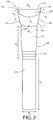
- Fig. 2 is a front elevation view of the applicator of Fig. 1 .
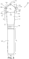
- Fig. 3 is a side elevation view of the applicator of Fig. 1 .
- the applicator 100 includes a handle 102 and a bristle tuft 104 connected to the handle 102.
- the bristle tuft 104 includes a plurality of bristles 110 grouped together and connected (either removably or permanently) to a distal end of the handle 102.
- the bristles 110 may be connected together and the bristle tuft 104 may be connected directly or indirectly to the handle 102 and/or the bristles 110 may individually or in groups may be connected to the handle 102.
- the bristle tuft 104 may be connected as a group to the handle 102 and may be secured by adhesive, fasteners, or the like.
- the bristle tuft 104 is connected by securing the bristles together, such as by tying them together, and then the bristles are connected via adhesive to a ferrule that is then connected such as by adhesive or a fastener to the handle 102.
- the bristles may be directly connected to the handle 102, e.g., secured by adhesive to the upper portion of the handle.
- other manners of connecting the bristle tuft 104 to the handle 102 are envisioned and the above examples are meant as illustrative only.
- the handle 102 is used by a user to direct the motion of the bristle tuft 104.
- the handle 104 may be varied based on the desired products to be applied by the applicator 100. For example, the height, width, shape, and other features of the handle 102 may be modified (see, e.g., Figs. 1A and 7 ).
- the handle 104 may include an upper handle 120, a lower handle 122, and a neck 118 separating the upper handle 120 from the lower handle 122.
- the lower handle 122 may be an elongated tubular member that includes soft or rounded edges. This shape may provide a comfortable gripping surface for the user as well as an aesthetically pleasing shape.
- the lower handle 122 may have a smaller diameter than the upper handle 120, which may allow the user to more easily grasp the lower handle 122 during use.
- the lower handle 122 may have a height H1 that is larger than a height of the upper handle 120.
- the lower handle may have a width W1 that may range between 10 to 30 mm and in one instance may be around 18 mm and may have a height H1 that may range between 60-100 mm and in one instance may be around 75 mm.
- the height H1 and width W1 of the lower handle 122 may be selected based on the desired products to be applied with the applicator 100.
- the handle 102 transitions from a top end of the lower handle 122 to form the neck 118.
- the neck 118 may include an aesthetically pleasing design that highlights the transition to the upper handle 120.
- the upper handle 120 in combination with the neck 118 may have a height H2 that may be smaller than the height H1 and may range between 30-60mm and in one example may be around 49mm.
- the width W2 of the top end of the upper handle 120 may be larger than the width W1 of the lower handle 122.
- the width W2 may range between 10 mm to 30 mm and in one embodiment may be 22 mm.
- the increased width at the upper end of the handle 120 allows the bristle tuft 104 to be larger and anchored in the handle 102. It should be noted that the design, shape, and dimensions of the handle 102 may be modified and the above examples are meant as illustrative only.
- the bristle tuft 104 is connected to a top end of the handle 102, in particular the bristle tuft 104 may be connected to the upper portion 122 of the handle 102 and in some embodiments the bristle tuft 104 may be removable from the handle 102.
- the bristle tuft 104 includes a plurality of bristles 110 anchored or secured to the handle 102 and are contoured to define an application end 106 for the applicator 100.
- the bristles 110 of the tuft 104 may be secured together independently of the handle, e.g., using adhesive, a base, or the like.
- the bristles 110 may be individually or in groups secured to the handle 102.
- the application end 106 defines a topography having a plurality of application surfaces and features that may be used to apply products to a user's skin.
- the various features of the application end 106 will be discussed in more detail below, but generally the application end 106 and features are configured to provide multiple functions and allow various types of cosmetic products to be applied to a user's skin.
- the bristles 110 may be natural hair bristles, synthetic fibers, or a combination of the two. Each of the bristles 110 may have approximately the same diameter or thickness, which may vary based on the desired uses for the applicator 100. Similarly, the density of the bristles 100 within the tuft 104 may also be varied based on the desired uses of the applicator. As some examples, the bristles 110 may have a diameter ranging between 0.10 mm and 0.01 mm, preferably around 0.07 mm.
- the bristles 100 may vary in texture along their length, for example, in some embodiments, the top ends of each of the bristles 110 may be softer than the body of each bristles or the bottom ends of the bristles 110. Further, some of the bristles 110 may have different textures than others, e.g., some bristles may be softer, more rigid, or the like, than other bristles.
- the length of the various bristles 110 defines the application end 106 and the contoured shape of the bristle tuft 104.
- the bristles 110 in the middle of the bristle tuft 104 may be longest to define a first feature, whereas the bristles 110 surround the perimeter of the tuft 104 may be varying lengths to define other features.
- the below discussion of the contours and topography of the bristle tuft 104 is meant to describe the varying lengths of bristles 110 in certain locations within the bristle tuft 104.
- the bristle tuft 104 may define various shapes on different sides thereof. For example, the front and back sides may define a first type of shape whereas the right and let sides may define a second type of shape. The features of the right and left sides of the bristle tuft will now be discussed.
- Fig. 4 is an enlarged view of the side view of the applicator.
- the right and left sides of the bristle tuft 104 may define a pentagon shape.
- a tuft side wall 108 may be defined by the bristles 110 on both the right and left sides of the applicator 100 and the application surfaces may not be defined on right and left sides.
- the tuft side wall 108 includes a first edge wall 124 having a bottom end 132 and a top end 128 and a second edge wall 126 having a bottom end 134 and a top end 130.
- the bottom ends 132, 134 of each of the edge walls 124, 126 may be defined by the handle top edge 138.
- the first edge wall 124 and the second edge wall 126 define the outer edges of the bristle tuft 104 as viewed from the right or left sides. Both of the edge walls 124, 126 may extend outward and upward from the respective bottom end 132, 134. In this manner, the edge walls 124, 126 may be angled relative to the upper handle 120.
- the first edge wall 124 and the second edge wall 126 may have approximately equal lengths that may be slightly less than of width W3 between the two top ends 128, 130.
- the first edge wall 124 and the second edge wall 126 may have a length L2 that is approximately 15 mm and the width W3 between the top ends 128, 130 may be approximately 28 mm.
- a first angle A may be defined between the top end of the handle 138 and the edge walls 124, 126.
- the first angle A may an obtuse angle ranging between greater than 90° and less than 180° and may range between 100° and 105° and preferably 103°.
- the tuft side wall 108 transitions at the perimeter to define the first top edge 140 and a second top edge 142.
- the two top edges 140, 142 extend from the top ends 128, 130 towards a center of the tuft side wall 108 and define a ridge end point 136 at an intersection between the two edges 140, 142.
- the first top edge 140 and the second top edge 142 each extend inwards at an angle from the respective top edge 128, 130.
- a second angle B e.g., a surface edge angle, may be defined between the first edge side wall 124 and the first top edge 140 and between the second edge side wall 126 and the second top edge 142.
- the second angle B may be obtuse, similar to the first angle A, but may be larger than the first angle A.
- the second angle B may range from 110° to 120°and in one embodiment may be about 115°.
- the top edges 140, 142 may have a length L1 that is approximately the same as the length L2 of the edge walls 124, 126.
- the top edges 140, 142 may have a length approximately equal to 15 mm.
- the first top edge 140 and the second top edge 142 define a third angle C or a ridge apex angle at their intersection.
- the third angle C may be less than both the first angle A and the second angle B, but is obtuse.
- the third angle C may range between 95° and 105° and preferably may be about 100°.
- the various angles A, B, C of the tuft side wall 108 define the features on the front and back top ends of the bristle tuft 104, e.g., the application end 106, as will be discussed in more detail below.
- the maximum width of the tuft side wall 108 may be defined between the first edge top end 128 and the second edge top end 130.
- a third width W may be defined between the top ends 128, 130.
- the third width W3 may be substantially any width, but as some examples may range between 25 mm and 35 mm and preferably may be about 28 mm.
- the maximum height of the tuft side wall 108 may be defined between the ridge end point 136 and the top end of the handle 138. In some embodiments, the maximum height H3 of the tuft side wall 108 may range between 20 mm and 30 mm and preferably may be around 25 mm.
- the right and left sides of the bristle tuft 104 may not be used to apply products to a user's face.
- the tuft sidewall 108 may extend the entire length of the bristle tuft 104 on the right and left sides of the applicator 100.
- the bristles 110 may be cut or contoured such that the application end 106 may be defined on the front and rear sides of the applicator 100. This configuration helps a user to better understand how to use the applicator 100 and which surfaces are meant for what tasks (e.g., contouring or coverage) and product types (e.g., cream, liquid, powder, etc.).
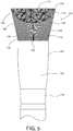
- Fig. 5 is an enlarged front view of the applicator.
- Fig. 6 is a diagram of a top plan view of the bristle tuft.
- the front and rear sides of the bristle tuft 104 may define the application end 106 for applying product to a user's skin.
- the application end 106 may define substantially a circular shape including a first wedge surface 112 and a second wedge surface 114 divided by a ridge 116.
- the two wedge surfaces 112, 114 may be used to apply cosmetic products across surfaces of a user's skin, as will be discussed in more detail below.
- the ridge 116 may be used to apply product into creases, lines, and other features on a user's face and may also be used to contour and provide aesthetic designs using cosmetic products.
- the ridge 116 may be defined by the tallest section of bristles 110 within the bristle tuft 104, e.g., the longest bristles.
- the ridge 116 substantially bisects the bristle tuft 104 and extends from a first ridge end 136 to a second ridge end 137.
- the length or width W4 of the ridge 116 may be varied based on the diameter of the bristle tuft 104, but in some embodiments may range between 25 mm to 35 mm and preferably may be 31.67 mm.
- the ridge 116 may be defined by one or more rows of bristles 110 aligned within the tuft 104. By varying the number of bristle rows, the thickness of the ridge 110 may be increased or decreased as desired. Additionally, in some embodiments, the ridge 110 may include bristles 110 that are somewhat more rigid than the other bristles within the tuft 104 which may provide increased contouring abilities to the ridge 116.
- the ridge 116 may define a crest for the applicator 100 and in some embodiments extends from the right side to the left side of the bristle tuft 104.
- the first wedge 112 and the second wedge 114 are angled upwards and intersect at the ridge 116 so that the ridge 116 defines the peak of the bristle tuft 104.
- the first and second wedges 112, 114 may be defined as substantially semicircular shaped surfaces and may be mirror images of one another. Additionally, the wedge surfaces 112, 114 may be symmetrically opposed to each other. In one embodiment, each of the wedge surface 112, 114 may have a radius or width that is approximately half of the diameter of the application end 106.
- the width W6 of the application end 106 may range between 25 mm to 35 mm and preferably around 31.67 mm and in this embodiment, the radius or width W7 of the first wedge surface 112 and the width W5 of the second wedge surface 114 may range between 12 mm to 18 mm and preferably 15.835 mm.
- first wedge 112 and the second wedge 114 may be angled relative to the ridge 116.
- a fifth angle E or a ridge angle, may be defined between the ridge 116 and the end of the outer boundary 150 of the first wedge 112 and the second wedge 114.
- the angle E may be an obtuse angle and in some embodiments may be larger than angle C but less than angles A and B. In one embodiment, angle E may range between 100° and 103° and preferably 101°. Due to the angle of the first and second wedge surfaces 112, 114 the entire wedge surface 112, 114 or a substantial portion thereof may be visible from the front or rear side of the applicator 100. This angle also provides an improved angle for allowing a user to apply cosmetic products to his or her face.
- the front and rear sides of the bristle tuft 104 may include a length of bristles 110 that extend upwards from the upper end 138 of the handle 102 prior to defining the wedge surfaces 112, 114.
- the bristle tuft 104 may include a front or rear wall 148 that is defined by the shape of the wedge surfaces 112, 114.
- the wedge surfaces 112, 114 may be semicircular shape and the boundary wall 150 may curve downwards from the ridge ends 136, 137 downwards the top end 138 of the handle 102.
- the height of the tuft front wall 148 (or rear wall depending on what direction the tuft is being viewed) varies along a width W2 of the handle 102.
- a center line of the front tuft wall 148 may have a height H5 that may be less than a height H3 of the front wall 148 at the ends 136, 137.
- the height H5 may be about 25 mm and the height H5 may be about 14 mm.
- the bristle tuft 104 may include front and second edge walls 144, 146 defining the shape of the bristle tuft 104 as viewed from the front and rear of the applicator 100.
- the first and second edge walls 144, 146 may extend outwards and upwards at an angle from the top end 138 of the handle 102.
- a fourth angle D or a bristle extension angle, may be defined between the top end 138 of the handle 102 or the bottom of the bristle tuft 104 and the first and second edge walls 144, 146.
- this angle D may be an obtuse angle.
- the angle D may be substantially the same dimensions as the angle A defined by the edge walls 124, 126 on the right and left sides of the bristle tuft.
- the angle D may range between 100° and 103° but preferably may be about 103°.
- the angles, heights, and widths discussed above are meant as illustrative only and other variations are envisioned. Also, it should be noted that although particular features are discussed as being on the right or left sides of the applicator 100, in other embodiments, these features may be on the front and back sides of the applicator 100. Further, although the various surfaces, edges, walls, and so on of the bristle tuft 104 have been discussed it should be noted that these may be the general shapes and edges defined by the bristle tuft 104. In particular, as the bristle tuft 104 includes multiple bristles 110 some bristles 110 may be slightly longer, shorter, or point in a particular direction than other bristles 110. Therefore, although the bristle tuft 104 may have a general shape, there may be stray bristles 110 or other bristles that vary from the exact boundary lines of the shapes.
- Fig. 7 illustrates a top isometric view of another example of the applicator of the present disclosure.
- the applicator 200 may include an elongated and thinner handle 202 as compared to the applicator 100 of Fig. 1 .
- the lower portion 220 of the handle may be substantially longer than the upper portion 220 as compared to the lower portion 120 of the applicator 100.
- the neck 218 and upper portion 218 may have a smaller diameter than the neck 118 and upper portion 118 of the applicator 100.
- the bristle tuft 204 of the applicator 200 may be substantially the same as the bristle tuft 104 and the applicator end 206 may include similar features to the applicator 100, such as the wedge surfaces 112, 114 and ridge 116, but the bristle tuft 204 and the features may be smaller.
- the diameter of the bristle tuft 204 may be reduced as compared to the bristle tuft 104.
- the bristle tuft 204 may be used in smaller surface areas, such as around a user's eyes, etc., where precision may be preferred over surface area for the bristles.
- Fig. 8A is a diagram of a user applying a cosmetic product with the applicator.
- a user may place the first wedge surface 112 in a desired product, e.g., cream, liquid, or powder.
- a desired product e.g., cream, liquid, or powder.
- the user directs the first wedge surface 112 to his or her face and moves the applicator 100 across his or her face.
- the bristles 110 are moved, such as due to the movement of the applicator 100, the product is deposited on the user's skin 300.
- the user may turn the applicator 100 around so that the second wedge 114 is facing his or her skin.
- the user then can smooth the product already applied to his or her skin. Because the wedge surfaces 112, 114 are substantially the same shape and size, the user can get approximately the same coverage and features as with the first wedge surface 112 but because the second wedge 114 may not include large amounts of product may be able to better smooth the previously applied product.
- Fig. 8B is a diagram of a user applying a cosmetic product using the ridge portion of the applicator.
- Fig. 8C is a cross-section view of the applicator and user's skin taken along line 8C-8C in Fig. 8B .
- the sharp angle of the ridge 116 the user can apply product into a crease 304 or other type of line or other sharp feature on his or her face or other areas of application.
- the ridge 116 may be used to provide additional contouring or specific lines of product in a desired area.
- the applicator 100 can be used for initial application, smoothing, creases, and contouring, the user can apply the cosmetic products as he or she desires but with a single multifunctional brush rather than multiple different brushes.
- joinder references are to be construed broadly and may include intermediate members between the connection of elements and relative movement between elements. As such, joinder references do not necessarily infer that two elements are directly connected and in fixed relation to each other.
Landscapes
- Physics & Mathematics (AREA)
- Geometry (AREA)
- Brushes (AREA)
Description
- The present disclosure relates to applicators and more particularly, to brushes for applying cosmetic products.
- Many types of cosmetic products may be applied by a brush. For example, liquids, creams, powders, compact powders, and so on, may all be applied to a user's face, neck, or other regions by a brush. Most cosmetic brushes have a rounded or flat shape suited to apply products to the flat surfaces of a user's face or body. However, these types of brushes do not fit into creases or deep lines of a user's face, such as the sides of the user's nose, smile line, crease between the chin and inferior lips, or the like. Accordingly, typically users must stretch the skin in those areas in order to allow conventional brushes to apply product into the creases or lines. Further, many cosmetic brushes are designed for a single function, such as applying loose powder, and so if a user wants to apply different products or create certain features, such as contour lines or the like, he or she typically will be required to change brushes. As such, there is a need for a multifunctional brush that can be used for multiple products, texturing, contouring, and can access all surfaces on a user's face.
US5450865 discloses an eyebrow brush that includes a brush tuft that has two planes coming together to form a tip portion with an acute angle. The tip is for drawing a sharp line, while the side planes are for providing a gradation or shading-off.US2011/0284019 also discloses a number of cosmetic brush configurations aimed at different applications, with the brushes including hairs with a dome-like shape. - The present disclosure includes an applicator according to the requirements of
claim 1, and may be for applying products to a surface, such as the skin of a person. The applicator includes a handle and a bristle tuft connected to the handle. The bristle tuft may include a plurality of contoured bristles that define multiple surfaces for applying products. The bristle tuft includes a first angled surface extending upwards from a first side of the bristle tuft, a second angled surface extending upwards from a second side of the bristle tuft, and a ridge defined at an intersection of the first angled surface and the second angled surface. - Another example of the present disclosure may take the form of a brush for applying cosmetic products including a handle and a plurality of bristles arranged in a cluster and connected to a top end of the handle, a top end of the plurality of bristles defining an application feature defining a first wedge surface, a second wedge surface, and a crest defined at an intersection between the first wedge and the second wedge.
- Yet another example may take the form of a cosmetic applicator for applying cosmetic products to a surface. The applicator may include a bristle tuft comprising a plurality of bristles secured together. The plurality of bristles may have varying lengths to define an applicator topography. The applicator topography includes a first angled wedge defined on a first side of the bristle tuft and angled towards a center of the bristle tuft, a second angled wedge defined on a second side of the bristle tuft and angled towards the center of the bristle tuft, and a ridge defined across the intersection of the first angled surface and the second angled surface, where a set of ridge bristles are longer than the remaining bristles in the plurality of bristles.
- While multiple examples are disclosed, still other examples of the present invention will become apparent to those skilled in the art from the following detailed description, which shows and describes illustrative examples of the invention. As will be realized, the invention is capable of modifications in various aspects, all without departing from the scope of the present invention. Accordingly, the drawings and detailed description are to be regarded as illustrative in nature and not restrictive.
-
-
Fig. 1A is a top front isometric view of an applicator. -
Fig. 1B is an enlarged view of the applicator. -
Fig. 2 is a front elevation view of the applicator. -
Fig. 3 is a side elevation view of the applicator. -
Fig. 4 is an enlarged side elevation view of the applicator. -
Fig. 5 is an enlarged front elevation view of the applicator. -
Fig. 6 is a schematic of a top plan view of an application end for the applicator ofFig. 1A . -
Fig. 7 is a top front isometric view of another example of an applicator. -
Fig. 8A is a diagram of the applicator ofFig. 1A being used to apply a cosmetic product to a user's face. -
Fig. 8B is a diagram of the applicator ofFig. 1A being used to apply a cosmetic product into a crease on a user's face. -
Fig. 8C is a simplified cross-section diagram of the applicator during use taken along line 8C-8C inFig. 8A . - Some examples of the present disclosure include a three-dimensional or multidimensional applicator that may be used to apply cosmetic products, paint, or the like. The applicator is multifunctional and may be used to apply a variety of different types products, such as liquids, creams, powders, and so on, to various surfaces of a user's face, including flat surfaces, creases, crevices, and lines. In one embodiment, the applicator includes a handle and a brush top including a plurality of contoured bristles. The bristles may be various lengths with predetermined shapes, densities, and lengths to define the application contours for the applicator. The contours may be selected to provide functionality, as well as provide an aesthetically pleasing design and a recognizable appearance to a user.
- In some embodiments, the contours of the bristles may be shaped so as to define symmetrically shaped, substantially planar, angled wedge surfaces that extend upwards from opposing sides of the brush top. The intersection of the two wedge surfaces defines a ridge that extends across a width of the brush top. In this embodiment, the bristles may form a pentagon shape on two sides of the bristle cluster as viewed from an elevation view of the applicator. The multiple contours defined by the shaped bristles allows a user to use the brush to apply cosmetic products to various areas of the face, without having to stretch his or her skin, switch brushes, or the like.
- In some embodiments, the wedge surfaces may be used to apply cosmetic products to flat and slightly curved areas of the face and the symmetry of the wedge surfaces allows a user to use a first wedge surface to do an initial application of the product and a second wedge surface to do a finishing or smoothing application of the product. For example, the first wedge surface may be covered in the product (e.g., dipped, swiped, or otherwise dusted) and then may be used to apply the product to the user's face. The second wedge surface, which may be "clean" or otherwise not have the product on the end of the bristles, may then be used to smooth the applied product on the user's face, e.g., eliminate streaks or the like.
- During application, the ridge or crest may be used to apply product to creases, sharp angles, and/or lines within a user's face (or other areas). For example, the user may apply product to the ridge and then may use the ridge to apply the product to the user's nose, smile line, chin crease, or the like. Due to the angled walls of the wedges, the ridge is oriented to fit within lines and creases, without requiring the user to stretch the skin in those locations. Further, the ridge may be used to precisely apply product to certain locations. For example, the sharp angle of the ridge may form a tip that may be used to accurately and specifically apply products to certain locations, which may be used to add contours or other detailed shapes and lines of product to a user's face. As some examples, the ridge may be used to apply product to the contours of a user's eyes and around the mouth.
- In some embodiments, the bristles may have a density that allows "buffering" of the product onto the user's skin. For example, the bristles may have a density similar to a dense sponge material that has some rigidity to maintain its shape as a user applies pressure downwards onto the skin, but also flexes around the user's skin. Further, the bristles may have sufficiently fine fibers to allow coverage of skin pores. For example, the bristles may have a diameter ranging between 0.10 mm and 0.01mm, and preferably may be 0.07 mm. The bristles are typically packed as tightly as possible into the upper end of the handle, so that the density of the bristles may be determined by the diameter of the handle and the diameter of each bristle.
- Turning to the figures, the applicator of the present disclosure will be discussed in more detail.
Fig. 1A is an isometric view of an applicator in accordance with the present disclosure.Fig. 1B is an enlarged isometric view of the applicator ofFig. 1A .Fig. 2 is a front elevation view of the applicator ofFig. 1 .Fig. 3 is a side elevation view of the applicator ofFig. 1 . With reference toFigs. 1A-3 , theapplicator 100 includes ahandle 102 and abristle tuft 104 connected to thehandle 102. The bristletuft 104 includes a plurality ofbristles 110 grouped together and connected (either removably or permanently) to a distal end of thehandle 102. Thebristles 110 may be connected together and thebristle tuft 104 may be connected directly or indirectly to thehandle 102 and/or thebristles 110 may individually or in groups may be connected to thehandle 102. In one embodiment, thebristle tuft 104 may be connected as a group to thehandle 102 and may be secured by adhesive, fasteners, or the like. In one embodiment, thebristle tuft 104 is connected by securing the bristles together, such as by tying them together, and then the bristles are connected via adhesive to a ferrule that is then connected such as by adhesive or a fastener to thehandle 102. In other embodiments, the bristles may be directly connected to thehandle 102, e.g., secured by adhesive to the upper portion of the handle. However, other manners of connecting thebristle tuft 104 to thehandle 102 are envisioned and the above examples are meant as illustrative only. - The
handle 102 is used by a user to direct the motion of thebristle tuft 104. Thehandle 104 may be varied based on the desired products to be applied by theapplicator 100. For example, the height, width, shape, and other features of thehandle 102 may be modified (see, e.g.,Figs. 1A and7 ). In one embodiment, thehandle 104 may include anupper handle 120, alower handle 122, and aneck 118 separating theupper handle 120 from thelower handle 122. - The
lower handle 122 may be an elongated tubular member that includes soft or rounded edges. This shape may provide a comfortable gripping surface for the user as well as an aesthetically pleasing shape. Thelower handle 122 may have a smaller diameter than theupper handle 120, which may allow the user to more easily grasp thelower handle 122 during use. Additionally, thelower handle 122 may have a height H1 that is larger than a height of theupper handle 120. Specifically, in one example, the lower handle may have a width W1 that may range between 10 to 30 mm and in one instance may be around 18 mm and may have a height H1 that may range between 60-100 mm and in one instance may be around 75 mm. The height H1 and width W1 of thelower handle 122 may be selected based on the desired products to be applied with theapplicator 100. - With continued reference to
Figs. 1A-3 , thehandle 102 transitions from a top end of thelower handle 122 to form theneck 118. In some embodiments, theneck 118 may include an aesthetically pleasing design that highlights the transition to theupper handle 120. Theupper handle 120 in combination with theneck 118 may have a height H2 that may be smaller than the height H1 and may range between 30-60mm and in one example may be around 49mm. Additionally, in some embodiments, the width W2 of the top end of theupper handle 120 may be larger than the width W1 of thelower handle 122. For example, the width W2 may range between 10 mm to 30 mm and in one embodiment may be 22 mm. The increased width at the upper end of thehandle 120 allows thebristle tuft 104 to be larger and anchored in thehandle 102. It should be noted that the design, shape, and dimensions of thehandle 102 may be modified and the above examples are meant as illustrative only. - As briefly discussed above, the
bristle tuft 104 is connected to a top end of thehandle 102, in particular thebristle tuft 104 may be connected to theupper portion 122 of thehandle 102 and in some embodiments thebristle tuft 104 may be removable from thehandle 102. The bristletuft 104 includes a plurality ofbristles 110 anchored or secured to thehandle 102 and are contoured to define anapplication end 106 for theapplicator 100. In embodiments where thebristle tuft 104 is removable from the handle, thebristles 110 of thetuft 104 may be secured together independently of the handle, e.g., using adhesive, a base, or the like. In other embodiments, thebristles 110 may be individually or in groups secured to thehandle 102. Theapplication end 106 defines a topography having a plurality of application surfaces and features that may be used to apply products to a user's skin. The various features of theapplication end 106 will be discussed in more detail below, but generally theapplication end 106 and features are configured to provide multiple functions and allow various types of cosmetic products to be applied to a user's skin. - The
bristles 110 may be natural hair bristles, synthetic fibers, or a combination of the two. Each of thebristles 110 may have approximately the same diameter or thickness, which may vary based on the desired uses for theapplicator 100. Similarly, the density of thebristles 100 within thetuft 104 may also be varied based on the desired uses of the applicator. As some examples, thebristles 110 may have a diameter ranging between 0.10 mm and 0.01 mm, preferably around 0.07 mm. Thebristles 100 may vary in texture along their length, for example, in some embodiments, the top ends of each of thebristles 110 may be softer than the body of each bristles or the bottom ends of thebristles 110. Further, some of thebristles 110 may have different textures than others, e.g., some bristles may be softer, more rigid, or the like, than other bristles. - The length of the
various bristles 110 defines theapplication end 106 and the contoured shape of thebristle tuft 104. For example, thebristles 110 in the middle of thebristle tuft 104 may be longest to define a first feature, whereas thebristles 110 surround the perimeter of thetuft 104 may be varying lengths to define other features. Accordingly, it should be noted that the below discussion of the contours and topography of thebristle tuft 104 is meant to describe the varying lengths ofbristles 110 in certain locations within thebristle tuft 104. The bristletuft 104 may define various shapes on different sides thereof. For example, the front and back sides may define a first type of shape whereas the right and let sides may define a second type of shape. The features of the right and left sides of the bristle tuft will now be discussed. -
Fig. 4 is an enlarged view of the side view of the applicator. With reference now toFigs. 3 and4 , the features of theapplication end 106 will now be discussed in more detail. In one embodiment, the right and left sides of thebristle tuft 104 may define a pentagon shape. For example, atuft side wall 108 may be defined by thebristles 110 on both the right and left sides of theapplicator 100 and the application surfaces may not be defined on right and left sides. In one embodiment, thetuft side wall 108 includes afirst edge wall 124 having abottom end 132 and atop end 128 and asecond edge wall 126 having abottom end 134 and atop end 130. The bottom ends 132, 134 of each of theedge walls top edge 138. - The
first edge wall 124 and thesecond edge wall 126 define the outer edges of thebristle tuft 104 as viewed from the right or left sides. Both of theedge walls bottom end edge walls upper handle 120. In one embodiment, thefirst edge wall 124 and thesecond edge wall 126 may have approximately equal lengths that may be slightly less than of width W3 between the two top ends 128, 130. For example, in one embodiment, thefirst edge wall 124 and thesecond edge wall 126 may have a length L2 that is approximately 15 mm and the width W3 between the top ends 128, 130 may be approximately 28 mm. - In one embodiment, a first angle A, or bristle extension angle, may be defined between the top end of the
handle 138 and theedge walls - With continued reference to
Figs. 3 and4 , after the top ends 128, 130, thetuft side wall 108 transitions at the perimeter to define the firsttop edge 140 and a secondtop edge 142. The twotop edges tuft side wall 108 and define aridge end point 136 at an intersection between the twoedges top edge 140 and the secondtop edge 142 each extend inwards at an angle from the respectivetop edge edge side wall 124 and the firsttop edge 140 and between the secondedge side wall 126 and the secondtop edge 142. The second angle B may be obtuse, similar to the first angle A, but may be larger than the first angle A. For example, the second angle B may range from 110° to 120°and in one embodiment may be about 115°. In one embodiment, thetop edges edge walls top edges - The first
top edge 140 and the secondtop edge 142 define a third angle C or a ridge apex angle at their intersection. In some embodiments, the third angle C may be less than both the first angle A and the second angle B, but is obtuse. For example, the third angle C may range between 95° and 105° and preferably may be about 100°. The various angles A, B, C of thetuft side wall 108 define the features on the front and back top ends of thebristle tuft 104, e.g., theapplication end 106, as will be discussed in more detail below. - The maximum width of the
tuft side wall 108 may be defined between the first edgetop end 128 and the second edgetop end 130. In particular, a third width W may be defined between the top ends 128, 130. The third width W3 may be substantially any width, but as some examples may range between 25 mm and 35 mm and preferably may be about 28 mm. The maximum height of thetuft side wall 108 may be defined between theridge end point 136 and the top end of thehandle 138. In some embodiments, the maximum height H3 of thetuft side wall 108 may range between 20 mm and 30 mm and preferably may be around 25 mm. - In some embodiments, the right and left sides of the
bristle tuft 104 may not be used to apply products to a user's face. For example, thetuft sidewall 108 may extend the entire length of thebristle tuft 104 on the right and left sides of theapplicator 100. In these embodiments, thebristles 110 may be cut or contoured such that theapplication end 106 may be defined on the front and rear sides of theapplicator 100. This configuration helps a user to better understand how to use theapplicator 100 and which surfaces are meant for what tasks (e.g., contouring or coverage) and product types (e.g., cream, liquid, powder, etc.). - The front and back sides of the applicator will now be discussed in more detail.
Fig. 5 is an enlarged front view of the applicator.Fig. 6 is a diagram of a top plan view of the bristle tuft. With reference toFigs. 2 ,5 , and6 , the front and rear sides of thebristle tuft 104 may define theapplication end 106 for applying product to a user's skin. In one embodiment, theapplication end 106 may define substantially a circular shape including afirst wedge surface 112 and asecond wedge surface 114 divided by aridge 116. The twowedge surfaces ridge 116 may be used to apply product into creases, lines, and other features on a user's face and may also be used to contour and provide aesthetic designs using cosmetic products. - The
ridge 116 may be defined by the tallest section ofbristles 110 within thebristle tuft 104, e.g., the longest bristles. Theridge 116 substantially bisects thebristle tuft 104 and extends from afirst ridge end 136 to asecond ridge end 137. The length or width W4 of theridge 116 may be varied based on the diameter of thebristle tuft 104, but in some embodiments may range between 25 mm to 35 mm and preferably may be 31.67 mm. Theridge 116 may be defined by one or more rows ofbristles 110 aligned within thetuft 104. By varying the number of bristle rows, the thickness of theridge 110 may be increased or decreased as desired. Additionally, in some embodiments, theridge 110 may includebristles 110 that are somewhat more rigid than the other bristles within thetuft 104 which may provide increased contouring abilities to theridge 116. - The
ridge 116 may define a crest for theapplicator 100 and in some embodiments extends from the right side to the left side of thebristle tuft 104. In particular, thefirst wedge 112 and thesecond wedge 114 are angled upwards and intersect at theridge 116 so that theridge 116 defines the peak of thebristle tuft 104. - With continued reference to
Figs. 2 ,5 , and6 , the first andsecond wedges wedge surface application end 106. For example, in one embodiment, the width W6 of theapplication end 106 may range between 25 mm to 35 mm and preferably around 31.67 mm and in this embodiment, the radius or width W7 of thefirst wedge surface 112 and the width W5 of thesecond wedge surface 114 may range between 12 mm to 18 mm and preferably 15.835 mm. - With reference to
Fig. 2 , thefirst wedge 112 and thesecond wedge 114 may be angled relative to theridge 116. For example, a fifth angle E, or a ridge angle, may be defined between theridge 116 and the end of theouter boundary 150 of thefirst wedge 112 and thesecond wedge 114. The angle E may be an obtuse angle and in some embodiments may be larger than angle C but less than angles A and B. In one embodiment, angle E may range between 100° and 103° and preferably 101°. Due to the angle of the first and second wedge surfaces 112, 114 theentire wedge surface applicator 100. This angle also provides an improved angle for allowing a user to apply cosmetic products to his or her face. - In some embodiments, the front and rear sides of the
bristle tuft 104 may include a length ofbristles 110 that extend upwards from theupper end 138 of thehandle 102 prior to defining the wedge surfaces 112, 114. With reference toFigs. 2 ,5 , and6 , thebristle tuft 104 may include a front orrear wall 148 that is defined by the shape of the wedge surfaces 112, 114. For example, in some embodiments the wedge surfaces 112, 114 may be semicircular shape and theboundary wall 150 may curve downwards from the ridge ends 136, 137 downwards thetop end 138 of thehandle 102. In this embodiment, the height of the tuft front wall 148 (or rear wall depending on what direction the tuft is being viewed) varies along a width W2 of thehandle 102. In particular, a center line of thefront tuft wall 148 may have a height H5 that may be less than a height H3 of thefront wall 148 at theends - Additionally, similar to the sides of the
applicator 100, thebristle tuft 104 may include front andsecond edge walls bristle tuft 104 as viewed from the front and rear of theapplicator 100. The first andsecond edge walls top end 138 of thehandle 102. In one embodiment, a fourth angle D, or a bristle extension angle, may be defined between thetop end 138 of thehandle 102 or the bottom of thebristle tuft 104 and the first andsecond edge walls edge walls - The angles, heights, and widths discussed above are meant as illustrative only and other variations are envisioned. Also, it should be noted that although particular features are discussed as being on the right or left sides of the
applicator 100, in other embodiments, these features may be on the front and back sides of theapplicator 100. Further, although the various surfaces, edges, walls, and so on of thebristle tuft 104 have been discussed it should be noted that these may be the general shapes and edges defined by thebristle tuft 104. In particular, as thebristle tuft 104 includesmultiple bristles 110 somebristles 110 may be slightly longer, shorter, or point in a particular direction thanother bristles 110. Therefore, although thebristle tuft 104 may have a general shape, there may bestray bristles 110 or other bristles that vary from the exact boundary lines of the shapes. -
Fig. 7 illustrates a top isometric view of another example of the applicator of the present disclosure. With reference toFig. 7 , in this example, theapplicator 200 may include an elongated and thinner handle 202 as compared to theapplicator 100 ofFig. 1 . Additionally, thelower portion 220 of the handle may be substantially longer than theupper portion 220 as compared to thelower portion 120 of theapplicator 100. Similarly, theneck 218 andupper portion 218 may have a smaller diameter than theneck 118 andupper portion 118 of theapplicator 100. - The bristle tuft 204 of the
applicator 200 may be substantially the same as thebristle tuft 104 and theapplicator end 206 may include similar features to theapplicator 100, such as the wedge surfaces 112, 114 andridge 116, but the bristle tuft 204 and the features may be smaller. In particular, the diameter of the bristle tuft 204 may be reduced as compared to the bristletuft 104. In this embodiment, the bristle tuft 204 may be used in smaller surface areas, such as around a user's eyes, etc., where precision may be preferred over surface area for the bristles. - A method of using the
applicator 100 for applying cosmetic products will now be discussed.Fig. 8A is a diagram of a user applying a cosmetic product with the applicator. With reference toFigs. 1A and8A , a user may place thefirst wedge surface 112 in a desired product, e.g., cream, liquid, or powder. Once thewedge surface 112 is coated or otherwise a sufficient amount of product is positioned on thebristles 110, the user directs thefirst wedge surface 112 to his or her face and moves theapplicator 100 across his or her face. As thebristles 110 are moved,, such as due to the movement of theapplicator 100, the product is deposited on the user'sskin 300. After the user has deposited the desired level of product onto his or herskin 300, he or she may turn theapplicator 100 around so that thesecond wedge 114 is facing his or her skin. Using theclean wedge surface 114, the user then can smooth the product already applied to his or her skin. Because the wedge surfaces 112, 114 are substantially the same shape and size, the user can get approximately the same coverage and features as with thefirst wedge surface 112 but because thesecond wedge 114 may not include large amounts of product may be able to better smooth the previously applied product. - After the desired product has been applied, or during application, the user may tilt the
applicator 100 so that theridge 116 is somewhat perpendicular to the user's skin and touching the skin.Fig. 8B is a diagram of a user applying a cosmetic product using the ridge portion of the applicator.Fig. 8C is a cross-section view of the applicator and user's skin taken along line 8C-8C inFig. 8B . With reference toFigs. 8A and 8C , using the sharp angle of theridge 116, the user can apply product into acrease 304 or other type of line or other sharp feature on his or her face or other areas of application. Additionally, theridge 116 may be used to provide additional contouring or specific lines of product in a desired area. - Because the
applicator 100 can be used for initial application, smoothing, creases, and contouring, the user can apply the cosmetic products as he or she desires but with a single multifunctional brush rather than multiple different brushes. - It should be noted that although the various examples discussed herein have been discussed with respect to cosmetic or makeup brushes, the devices and techniques may be applied in a variety of applicators, such as, but not limited to, paint brushes, cooking brushes (e.g., pastry brushes, basting brushes) and so on. As such, it should be understood that the discussion of any particular example is meant as exemplary only.
- It should be noted that any of the features in the various examples and embodiments provided herein may be interchangeable and/or replaceable with any other example or embodiment. As such, the discussion of any component or element with respect to a particular example or embodiment is meant as illustrative only.
- All directional references (e.g., upper, lower, upward, downward, left, right, leftward, rightward, top, bottom, above, below, vertical, horizontal, clockwise, and counterclockwise) are used only for identification purposes to aid the reader's understanding of the examples of the invention, and do not create limitations, particularly as to the position, orientation, or use of the invention unless specifically set forth in the claims. Joinder references
- (e.g., attached, coupled, connected, joined and the like) are to be construed broadly and may include intermediate members between the connection of elements and relative movement between elements. As such, joinder references do not necessarily infer that two elements are directly connected and in fixed relation to each other.
- In some instances, components are described by reference to "ends" having a particular characteristic and/or being connected with another part. However, those skilled in the art will recognize that the present invention is not limited to components which terminate immediately beyond their point of connection with other parts. Thus the term "end" should be broadly interpreted, in a manner that includes areas adjacent rearward, forward of or otherwise near the terminus of a particular element, link, component, part, member or the like. In methodologies directly or indirectly set forth herein, various steps and operations are described in one possible order of operation but those skilled in the art will recognize the steps and operation may be rearranged, replaced or eliminated without necessarily departing from the scope of the present invention. It is intended that all matter contained in the above description or shown in the accompanying drawings shall be interpreted as illustrative only and not limiting. Changes in detail or structure may be made without departing from the scope of the invention as defined in the appended claims.
Claims (11)
- An applicator (100) comprising:a handle (102); anda bristle tuft (104) connected to the handle (102), the bristle tuft (104) comprisinga first angled surface (112) extending upwards from a first side of the bristle tuft; anda second angled surface (114) extending upwards from a second side of the bristle tuft;a ridge (116) defined at an intersection of the first angled surface and the second angled surface,wherein a ridge angle (E) is defined between a first end of the first angled surface and a first end of the ridge and between a first end of the second angled surface and a second end of the ridge; andcharacterized in thatthe first angled surface (112) is semicircular shaped; andthe second angled surface (114) is semicircular shaped; whereinthe ridge (116) forms a common edge between the first angled surface and the second angled surface, wherein the bristle tuft further comprising: a first top edge (140) and a second top edge (142) extending from top ends of the bristle tuft,wherein an intersection of the first top edge and the second top edge defines a ridge apex angle (C) at the intersection; and wherein the ridge apex angle is an obtuse angle.
- The applicator (100) of claim 1, wherein the first angled surface, the second angled surface, and the ridge define an application end of the bristle tuft.
- The applicator (100) of any of the preceding claims, wherein the bristle tuft (104) further comprises a pentagon shaped tuft side wall on at least one side of the bristle tuft.
- The applicator (100) of claim 3, wherein an end point (136) of the ridge (116) defines a point in the pentagon shaped tuft side wall.
- The applicator (100) of any of the preceding claims, wherein the first angled surface (112) and the second angled surface (114) are symmetrical.
- The applicator (100) of any of the preceding claims, wherein the first angled surface (112) and the second angled surface (114) are mirror images.
- The applicator (100) of any of the preceding claims, the handle (102) and bristle tuft (104) being configured as a brush for applying cosmetic products, wherein the bristle tuft (104) comprises a plurality of bristles (110) arranged in a cluster and connected to a top end of the handle (102), a top end of the plurality of bristles defining an application feature defininga first wedge surface (112);a second wedge surface (114); anda crest defined at an intersection between the first wedge and the second wedge.
- The applicator (100) of claim 7, wherein:the first wedge surface (112) and the second wedge surface (114) are mirror images;the crest bisects the application feature;the ridge (116) comprises the longest bristles within the plurality of bristles;the first wedge surface (112) and the second wedge surface (114) are semicircular surfaces;the first wedge surface (112) is angled upwards from a front of the cluster towards the crest; and/orthe plurality of bristles (110) extend outwards from the top end of the handle (102) at an obtuse angle.
- The applicator (100) of any of the preceding claims, being configured for applying cosmetic products, wherein the bristle tuft (104) comprises a plurality of bristles (110) secured together, and wherein the plurality of bristles (110) are various lengths to define an applicator topography comprising:a first angled wedge (112) defined on a first side of the bristle tuft and angled towards a center of the bristle tuft;a second angled wedge (114) defined on a second side of the bristle tuft and angled towards the center of the bristle tuft; anda ridge (116) defined across the intersection of the first angled surface and the second angled surface, wherein a set of ridge bristles are longer than the remaining bristles in the plurality of bristles.
- The applicator (100) of claim 9, wherein the first angled wedge (112) and the second angled wedge (114) are mirror images of one another.
- The applicator (100) of any of claims 9-10, wherein the ridge (116) bisects the bristle tuft.
Applications Claiming Priority (1)
| Application Number | Priority Date | Filing Date | Title |
|---|---|---|---|
| US14/482,062 US9675167B2 (en) | 2014-09-10 | 2014-09-10 | Multidimensional applicator |
Publications (2)
| Publication Number | Publication Date |
|---|---|
| EP2995218A1 EP2995218A1 (en) | 2016-03-16 |
| EP2995218B1 true EP2995218B1 (en) | 2019-04-03 |
Family
ID=52023333
Family Applications (1)
| Application Number | Title | Priority Date | Filing Date |
|---|---|---|---|
| EP14197599.5A Active EP2995218B1 (en) | 2014-09-10 | 2014-12-12 | Multidimensional applicator |
Country Status (3)
| Country | Link |
|---|---|
| US (1) | US9675167B2 (en) |
| EP (1) | EP2995218B1 (en) |
| CN (1) | CN204499788U (en) |
Families Citing this family (18)
| Publication number | Priority date | Publication date | Assignee | Title |
|---|---|---|---|---|
| US20160262528A1 (en) * | 2015-02-24 | 2016-09-15 | Anisa International, Inc. | Oval-shaped collection of brushes and method for using same |
| ITUB20153010A1 (en) * | 2015-08-07 | 2017-02-07 | Pennelli Faro S R L | PERFECTED BRUSH |
| USD791488S1 (en) * | 2015-12-15 | 2017-07-11 | Indeutsch Industries Private Limited | Cosmetic brush |
| USD782198S1 (en) * | 2016-01-22 | 2017-03-28 | F.S. Korea Industries Inc | Cosmetic brush |
| USD787194S1 (en) * | 2016-01-27 | 2017-05-23 | F.S. Korea Industries Inc. | Cosmetic brush |
| USD801058S1 (en) | 2017-03-13 | 2017-10-31 | Sigma Enterprises, Llc | Cosmetic brush |
| USD822277S1 (en) | 2017-04-04 | 2018-07-03 | Sigma Enterprises, Llc | Cosmetic applicator |
| USD859004S1 (en) * | 2017-05-15 | 2019-09-10 | Kotobuki & Co., Ltd. | Cosmetic container |
| EP3673765B1 (en) | 2017-08-21 | 2024-01-03 | Sinwa Corporation | Cosmetic applicator |
| ES2997125T3 (en) * | 2017-10-20 | 2025-02-14 | Oreal | Method for manufacturing a personalized applicator for the application of a cosmetic composition |
| FR3073132B1 (en) * | 2017-11-06 | 2019-12-13 | Cosmogen Sas | BRUSH FOR FLUID OR VISCOUS COSMETICS |
| USD900480S1 (en) * | 2018-08-01 | 2020-11-03 | Fm Brush Co., Inc. | Angled chisel brush |
| CN109820811A (en) * | 2019-04-02 | 2019-05-31 | 陈晓艳 | A kind of anti-aging technology based on tcm therapy |
| USD939220S1 (en) * | 2019-05-02 | 2021-12-28 | Cosmogen Sas | Cosmetic applicator |
| USD869176S1 (en) * | 2019-05-08 | 2019-12-10 | Kotobuki & Co., Ltd. | Cosmetic container |
| USD986523S1 (en) * | 2020-03-19 | 2023-05-16 | Carl Freudenberg Kg | V-trim broom |
| USD956430S1 (en) | 2020-12-09 | 2022-07-05 | Anisa International, Inc. | Diamond-shaped brush head |
| US11517937B1 (en) * | 2021-08-02 | 2022-12-06 | David JOHANSSON | Method of painting flowers with modified makeup brush or alternative specially configured brush |
Family Cites Families (62)
| Publication number | Priority date | Publication date | Assignee | Title |
|---|---|---|---|---|
| US2122980A (en) | 1934-11-22 | 1938-07-05 | Grumbacher Walter | Brush |
| US2849740A (en) | 1956-03-13 | 1958-09-02 | Pauker Frances | Tapered broom |
| US3333289A (en) * | 1966-11-17 | 1967-08-01 | Alice M Maughan | Brush |
| USD249600S (en) | 1976-09-20 | 1978-09-26 | Bowman Trading Co., Inc. | Make-up brush |
| USD267986S (en) | 1980-12-22 | 1983-02-22 | Max Factor & Co. | Brush for applying makeup |
| US4360940A (en) | 1981-04-01 | 1982-11-30 | Smith Louise W | Corner brush |
| USD278952S (en) | 1984-04-04 | 1985-05-28 | Stuart Kalinsky | Cosmetic brush |
| US5862559A (en) | 1988-09-23 | 1999-01-26 | Hunter; Frank | Toothbrush for interproximal and periodontal pocket cleaning |
| USD304392S (en) * | 1989-02-27 | 1989-11-07 | Reich Maurice M | Cosmetic brush |
| US4952894A (en) | 1989-07-10 | 1990-08-28 | Raytheon Company | Waveguide feed network for antenna array |
| USD324776S (en) | 1989-12-20 | 1992-03-24 | Griffin Quintin L | Combined cosmetic dispensing brush and cap therefor |
| US5450865A (en) | 1990-11-08 | 1995-09-19 | Y. S. Park New York Co., Ltd. | Makeup brush |
| CA69199S (en) | 1991-03-03 | 1991-08-27 | John Jansen | Chimney cleaning brush |
| USD350853S (en) | 1992-06-30 | 1994-09-27 | L'oreal | Blush brush |
| USD380615S (en) | 1995-02-24 | 1997-07-08 | Roberts David J | Paintbrush |
| US5542144A (en) | 1995-04-19 | 1996-08-06 | Forsline; Ladd B. | Silicone paint brush artist's tool |
| JPH09191935A (en) | 1996-01-23 | 1997-07-29 | Reizou Shiyouji | Toothbrush |
| USD387564S (en) | 1996-10-22 | 1997-12-16 | Neil Ellis Talbot | V shaped utility broom |
| JPH10165224A (en) | 1996-12-12 | 1998-06-23 | Shiseido Co Ltd | Make-up brush |
| US5906434A (en) | 1997-02-28 | 1999-05-25 | The Research Foundation Of State University Of New York At Stony Brook | Rotating triangular drum for incubating probes with membrane-immobilized ligands |
| USD427065S (en) | 1998-08-28 | 2000-06-27 | Recot, Inc. | Tubular food container |
| USD439838S1 (en) | 1998-08-28 | 2001-04-03 | Recot, Inc. | Tubular food container |
| US5943836A (en) | 1998-09-10 | 1999-08-31 | Don De Cristo Concrete Accessories, Inc. | Protective cover for concrete reinforcing bar |
| USD427777S (en) | 1999-03-04 | 2000-07-11 | Heung-Tae Kim | Make-up brush |
| USD421846S (en) | 1999-05-05 | 2000-03-28 | L'oreal S.A. | Brush |
| USD428706S (en) | 1999-11-12 | 2000-08-01 | Wayne Thunderchild | Cement step finishing brush |
| USD442083S1 (en) | 1999-12-10 | 2001-05-15 | Waterhill, Llc | Container |
| USD450189S1 (en) | 2000-05-31 | 2001-11-13 | Jeffrey Mink | Brush |
| USD446654S1 (en) | 2000-10-03 | 2001-08-21 | Berni Irio E C. S.N.C. | Broom |
| USD479917S1 (en) | 2002-04-19 | 2003-09-30 | F. M. Brush Co., Inc. | Brush with angled fan-shaped bristles |
| USD479918S1 (en) | 2002-04-19 | 2003-09-30 | F.M. Brush Co., Inc. | Brush with oval wave-shaped bristles |
| USD471018S1 (en) | 2002-04-19 | 2003-03-04 | Mink Jeffrey A | Brush with angled wave-shaped bristles |
| CA101224S (en) | 2002-05-15 | 2004-03-01 | Ruth Lynnette Clapperton | Brush |
| US20050000976A1 (en) | 2003-07-03 | 2005-01-06 | Keberlein Gerald J. | Wedged tissue container |
| USD518962S1 (en) | 2004-11-22 | 2006-04-18 | Hayco Manufacturing Limited | Brush |
| US20060123576A1 (en) * | 2004-12-13 | 2006-06-15 | Howard Nancy E | Brush for applying for nail polish |
| USD529815S1 (en) | 2005-02-16 | 2006-10-10 | Frasier Michael A | Carton for artificial camping log |
| USD591618S1 (en) | 2005-07-12 | 2009-05-05 | Trinova Design, Llc | Wedge shaped container configuration with packaging material |
| US20070151061A1 (en) | 2005-12-30 | 2007-07-05 | Gregory Mink | Applicator brush with cylindrical ferrule and angled tip |
| US7895698B2 (en) | 2006-12-18 | 2011-03-01 | Fm Brush Co., Inc. | Applicator brush |
| USD572010S1 (en) | 2007-08-03 | 2008-07-01 | Riaz Claudio S | Cosmetic brush |
| USD571559S1 (en) | 2007-08-07 | 2008-06-24 | Claudio S Riaz | Cosmetic brush |
| USD603610S1 (en) | 2007-10-23 | 2009-11-10 | Geka Brush Gmbh | Cosmetic applicator |
| USD599116S1 (en) | 2007-10-23 | 2009-09-01 | Geka Brush Gmbh | Cosmetic applicator |
| USD672233S1 (en) | 2008-01-03 | 2012-12-11 | Access Business Group International Llc | Carton |
| USD575635S1 (en) | 2008-01-23 | 2008-08-26 | Jeff Rozenzweig | Product package |
| USD661600S1 (en) | 2008-06-27 | 2012-06-12 | The Clorox Company | Wipes canister |
| US8562352B2 (en) | 2008-07-09 | 2013-10-22 | Andrea B. Fairweather | Systems, methods and apparatus involving Fairweather faces cosmetics brushes and face charts |
| FR2933587B1 (en) * | 2008-07-09 | 2011-10-21 | Oreal | BRUSH FOR APPLYING A COSMETIC COMPOSITION WITH SYNTHETIC HAIR |
| USD591512S1 (en) | 2008-09-02 | 2009-05-05 | The Procter & Gamble Company | Cosmetic applicator |
| USD625522S1 (en) | 2008-09-22 | 2010-10-19 | Riaz Claudio S | Cosmetic brush |
| USD601349S1 (en) | 2009-05-12 | 2009-10-06 | Michael Wales | Wedge shaped grill brush |
| USD626338S1 (en) | 2009-08-06 | 2010-11-02 | Jka, Inc. | Eye shadow brush |
| JP2011087675A (en) | 2009-10-21 | 2011-05-06 | Shiseido Co Ltd | Cosmetic brush and makeup method using the same |
| USD695102S1 (en) | 2011-09-16 | 2013-12-10 | Trinova Design, Llc | Container |
| USD693366S1 (en) | 2011-09-22 | 2013-11-12 | Isaac S. Daniel | Computer screen with icon |
| USD663957S1 (en) | 2011-09-30 | 2012-07-24 | Loew-Cornell, Llc | Brush head |
| USD686417S1 (en) | 2011-10-06 | 2013-07-23 | Loew-Cornell, Llc | Brush head |
| USD710617S1 (en) | 2012-03-26 | 2014-08-12 | Fm Brush Co., Inc. | Brush with wave-shaped bristles |
| US9055807B2 (en) | 2013-01-16 | 2015-06-16 | James C. Dale | Wedge-shaped paintbrush |
| USD706542S1 (en) | 2014-01-13 | 2014-06-10 | Michael Kors, Llc | Cosmetic brush |
| USD718941S1 (en) | 2014-03-27 | 2014-12-09 | Shiseido Co., Ltd. | Cosmetic brush |
-
2014
- 2014-09-10 US US14/482,062 patent/US9675167B2/en active Active
- 2014-12-12 EP EP14197599.5A patent/EP2995218B1/en active Active
-
2015
- 2015-01-09 CN CN201520016663.2U patent/CN204499788U/en not_active Expired - Lifetime
Non-Patent Citations (1)
| Title |
|---|
| None * |
Also Published As
| Publication number | Publication date |
|---|---|
| EP2995218A1 (en) | 2016-03-16 |
| US20160066681A1 (en) | 2016-03-10 |
| US9675167B2 (en) | 2017-06-13 |
| CN204499788U (en) | 2015-07-29 |
Similar Documents
| Publication | Publication Date | Title |
|---|---|---|
| EP2995218B1 (en) | Multidimensional applicator | |
| EP2367456B1 (en) | Ergonomic cosmetic brush | |
| US20210401150A1 (en) | Cosmetic applicator with flexible and rigid portions | |
| US9826815B2 (en) | Application device | |
| US9668564B2 (en) | Cosmetic product applicator, device and associated method | |
| JP5074713B2 (en) | Applicator for applying the composition to the eyelashes and / or eyebrows | |
| US6601591B1 (en) | Ergonomic cosmetic applicator | |
| US7779847B2 (en) | Apparatus and methods for manipulating hair processing materials | |
| JP4414956B2 (en) | Device for applying substances to hair, especially eyelashes or eyebrows | |
| US20140166041A1 (en) | Cosmetic brushes having improved carry and application features | |
| EP2769641A1 (en) | Cosmetic applicator | |
| JP2019088935A (en) | Applicator for applying a cosmetic product | |
| JP2020062413A (en) | Applicator for applying beauty products | |
| JP2007167615A (en) | Device for applying substance to hair | |
| US11925250B2 (en) | Cosmetic applicator | |
| US10441055B2 (en) | Packaging and application device | |
| US20110180090A1 (en) | Application tool for applying a product to hair | |
| CN115915999A (en) | Cosmetic applicator having a cavity supported by a support arm | |
| CN108236192A (en) | Hair cosmetic composition applicator | |
| US9839282B1 (en) | Cosmetic brush device | |
| JP3809463B1 (en) | Handle structure | |
| CA2324996C (en) | Ergonomic cosmetic applicator | |
| EP4588396A1 (en) | A cosmetic applicator | |
| KR200496711Y1 (en) | cosmetic tool | |
| KR200424803Y1 (en) | Eyelash Cosmetic Mascara Brush |
Legal Events
| Date | Code | Title | Description |
|---|---|---|---|
| PUAI | Public reference made under article 153(3) epc to a published international application that has entered the european phase |
Free format text: ORIGINAL CODE: 0009012 |
|
| AK | Designated contracting states |
Kind code of ref document: A1 Designated state(s): AL AT BE BG CH CY CZ DE DK EE ES FI FR GB GR HR HU IE IS IT LI LT LU LV MC MK MT NL NO PL PT RO RS SE SI SK SM TR |
|
| AX | Request for extension of the european patent |
Extension state: BA ME |
|
| 17P | Request for examination filed |
Effective date: 20160914 |
|
| RAP1 | Party data changed (applicant data changed or rights of an application transferred) |
Owner name: SIGMA ENTERPRISES, LLC |
|
| RBV | Designated contracting states (corrected) |
Designated state(s): AL AT BE BG CH CY CZ DE DK EE ES FI FR GB GR HR HU IE IS IT LI LT LU LV MC MK MT NL NO PL PT RO RS SE SI SK SM TR |
|
| RIN1 | Information on inventor provided before grant (corrected) |
Inventor name: XAVIER FILHO, RENE Inventor name: RODRIGES OLIVEIRA XAVIER, SIMONE |
|
| STAA | Information on the status of an ep patent application or granted ep patent |
Free format text: STATUS: EXAMINATION IS IN PROGRESS |
|
| 17Q | First examination report despatched |
Effective date: 20170331 |
|
| RIC1 | Information provided on ipc code assigned before grant |
Ipc: A45D 40/26 20060101ALI20170324BHEP Ipc: A46B 9/02 20060101AFI20170324BHEP |
|
| GRAP | Despatch of communication of intention to grant a patent |
Free format text: ORIGINAL CODE: EPIDOSNIGR1 |
|
| STAA | Information on the status of an ep patent application or granted ep patent |
Free format text: STATUS: GRANT OF PATENT IS INTENDED |
|
| INTG | Intention to grant announced |
Effective date: 20181127 |
|
| GRAS | Grant fee paid |
Free format text: ORIGINAL CODE: EPIDOSNIGR3 |
|
| GRAA | (expected) grant |
Free format text: ORIGINAL CODE: 0009210 |
|
| STAA | Information on the status of an ep patent application or granted ep patent |
Free format text: STATUS: THE PATENT HAS BEEN GRANTED |
|
| AK | Designated contracting states |
Kind code of ref document: B1 Designated state(s): AL AT BE BG CH CY CZ DE DK EE ES FI FR GB GR HR HU IE IS IT LI LT LU LV MC MK MT NL NO PL PT RO RS SE SI SK SM TR |
|
| REG | Reference to a national code |
Ref country code: GB Ref legal event code: FG4D |
|
| REG | Reference to a national code |
Ref country code: CH Ref legal event code: EP Ref country code: AT Ref legal event code: REF Ref document number: 1114670 Country of ref document: AT Kind code of ref document: T Effective date: 20190415 |
|
| REG | Reference to a national code |
Ref country code: DE Ref legal event code: R096 Ref document number: 602014043943 Country of ref document: DE |
|
| REG | Reference to a national code |
Ref country code: IE Ref legal event code: FG4D |
|
| REG | Reference to a national code |
Ref country code: NL Ref legal event code: MP Effective date: 20190403 |
|
| REG | Reference to a national code |
Ref country code: LT Ref legal event code: MG4D |
|
| REG | Reference to a national code |
Ref country code: AT Ref legal event code: MK05 Ref document number: 1114670 Country of ref document: AT Kind code of ref document: T Effective date: 20190403 |
|
| PG25 | Lapsed in a contracting state [announced via postgrant information from national office to epo] |
Ref country code: NL Free format text: LAPSE BECAUSE OF FAILURE TO SUBMIT A TRANSLATION OF THE DESCRIPTION OR TO PAY THE FEE WITHIN THE PRESCRIBED TIME-LIMIT Effective date: 20190403 |
|
| PG25 | Lapsed in a contracting state [announced via postgrant information from national office to epo] |
Ref country code: PT Free format text: LAPSE BECAUSE OF FAILURE TO SUBMIT A TRANSLATION OF THE DESCRIPTION OR TO PAY THE FEE WITHIN THE PRESCRIBED TIME-LIMIT Effective date: 20190803 Ref country code: AL Free format text: LAPSE BECAUSE OF FAILURE TO SUBMIT A TRANSLATION OF THE DESCRIPTION OR TO PAY THE FEE WITHIN THE PRESCRIBED TIME-LIMIT Effective date: 20190403 Ref country code: SE Free format text: LAPSE BECAUSE OF FAILURE TO SUBMIT A TRANSLATION OF THE DESCRIPTION OR TO PAY THE FEE WITHIN THE PRESCRIBED TIME-LIMIT Effective date: 20190403 Ref country code: HR Free format text: LAPSE BECAUSE OF FAILURE TO SUBMIT A TRANSLATION OF THE DESCRIPTION OR TO PAY THE FEE WITHIN THE PRESCRIBED TIME-LIMIT Effective date: 20190403 Ref country code: CZ Free format text: LAPSE BECAUSE OF FAILURE TO SUBMIT A TRANSLATION OF THE DESCRIPTION OR TO PAY THE FEE WITHIN THE PRESCRIBED TIME-LIMIT Effective date: 20190403 Ref country code: LT Free format text: LAPSE BECAUSE OF FAILURE TO SUBMIT A TRANSLATION OF THE DESCRIPTION OR TO PAY THE FEE WITHIN THE PRESCRIBED TIME-LIMIT Effective date: 20190403 Ref country code: ES Free format text: LAPSE BECAUSE OF FAILURE TO SUBMIT A TRANSLATION OF THE DESCRIPTION OR TO PAY THE FEE WITHIN THE PRESCRIBED TIME-LIMIT Effective date: 20190403 Ref country code: FI Free format text: LAPSE BECAUSE OF FAILURE TO SUBMIT A TRANSLATION OF THE DESCRIPTION OR TO PAY THE FEE WITHIN THE PRESCRIBED TIME-LIMIT Effective date: 20190403 Ref country code: NO Free format text: LAPSE BECAUSE OF FAILURE TO SUBMIT A TRANSLATION OF THE DESCRIPTION OR TO PAY THE FEE WITHIN THE PRESCRIBED TIME-LIMIT Effective date: 20190703 |
|
| PG25 | Lapsed in a contracting state [announced via postgrant information from national office to epo] |
Ref country code: PL Free format text: LAPSE BECAUSE OF FAILURE TO SUBMIT A TRANSLATION OF THE DESCRIPTION OR TO PAY THE FEE WITHIN THE PRESCRIBED TIME-LIMIT Effective date: 20190403 Ref country code: RS Free format text: LAPSE BECAUSE OF FAILURE TO SUBMIT A TRANSLATION OF THE DESCRIPTION OR TO PAY THE FEE WITHIN THE PRESCRIBED TIME-LIMIT Effective date: 20190403 Ref country code: BG Free format text: LAPSE BECAUSE OF FAILURE TO SUBMIT A TRANSLATION OF THE DESCRIPTION OR TO PAY THE FEE WITHIN THE PRESCRIBED TIME-LIMIT Effective date: 20190703 Ref country code: GR Free format text: LAPSE BECAUSE OF FAILURE TO SUBMIT A TRANSLATION OF THE DESCRIPTION OR TO PAY THE FEE WITHIN THE PRESCRIBED TIME-LIMIT Effective date: 20190704 Ref country code: LV Free format text: LAPSE BECAUSE OF FAILURE TO SUBMIT A TRANSLATION OF THE DESCRIPTION OR TO PAY THE FEE WITHIN THE PRESCRIBED TIME-LIMIT Effective date: 20190403 |
|
| PG25 | Lapsed in a contracting state [announced via postgrant information from national office to epo] |
Ref country code: IS Free format text: LAPSE BECAUSE OF FAILURE TO SUBMIT A TRANSLATION OF THE DESCRIPTION OR TO PAY THE FEE WITHIN THE PRESCRIBED TIME-LIMIT Effective date: 20190803 Ref country code: AT Free format text: LAPSE BECAUSE OF FAILURE TO SUBMIT A TRANSLATION OF THE DESCRIPTION OR TO PAY THE FEE WITHIN THE PRESCRIBED TIME-LIMIT Effective date: 20190403 |
|
| REG | Reference to a national code |
Ref country code: DE Ref legal event code: R097 Ref document number: 602014043943 Country of ref document: DE |
|
| PG25 | Lapsed in a contracting state [announced via postgrant information from national office to epo] |
Ref country code: DK Free format text: LAPSE BECAUSE OF FAILURE TO SUBMIT A TRANSLATION OF THE DESCRIPTION OR TO PAY THE FEE WITHIN THE PRESCRIBED TIME-LIMIT Effective date: 20190403 Ref country code: RO Free format text: LAPSE BECAUSE OF FAILURE TO SUBMIT A TRANSLATION OF THE DESCRIPTION OR TO PAY THE FEE WITHIN THE PRESCRIBED TIME-LIMIT Effective date: 20190403 Ref country code: SK Free format text: LAPSE BECAUSE OF FAILURE TO SUBMIT A TRANSLATION OF THE DESCRIPTION OR TO PAY THE FEE WITHIN THE PRESCRIBED TIME-LIMIT Effective date: 20190403 Ref country code: EE Free format text: LAPSE BECAUSE OF FAILURE TO SUBMIT A TRANSLATION OF THE DESCRIPTION OR TO PAY THE FEE WITHIN THE PRESCRIBED TIME-LIMIT Effective date: 20190403 |
|
| PLBE | No opposition filed within time limit |
Free format text: ORIGINAL CODE: 0009261 |
|
| STAA | Information on the status of an ep patent application or granted ep patent |
Free format text: STATUS: NO OPPOSITION FILED WITHIN TIME LIMIT |
|
| PG25 | Lapsed in a contracting state [announced via postgrant information from national office to epo] |
Ref country code: IT Free format text: LAPSE BECAUSE OF FAILURE TO SUBMIT A TRANSLATION OF THE DESCRIPTION OR TO PAY THE FEE WITHIN THE PRESCRIBED TIME-LIMIT Effective date: 20190403 Ref country code: SM Free format text: LAPSE BECAUSE OF FAILURE TO SUBMIT A TRANSLATION OF THE DESCRIPTION OR TO PAY THE FEE WITHIN THE PRESCRIBED TIME-LIMIT Effective date: 20190403 |
|
| 26N | No opposition filed |
Effective date: 20200106 |
|
| PG25 | Lapsed in a contracting state [announced via postgrant information from national office to epo] |
Ref country code: TR Free format text: LAPSE BECAUSE OF FAILURE TO SUBMIT A TRANSLATION OF THE DESCRIPTION OR TO PAY THE FEE WITHIN THE PRESCRIBED TIME-LIMIT Effective date: 20190403 |
|
| PG25 | Lapsed in a contracting state [announced via postgrant information from national office to epo] |
Ref country code: SI Free format text: LAPSE BECAUSE OF FAILURE TO SUBMIT A TRANSLATION OF THE DESCRIPTION OR TO PAY THE FEE WITHIN THE PRESCRIBED TIME-LIMIT Effective date: 20190403 |
|
| REG | Reference to a national code |
Ref country code: CH Ref legal event code: PL |
|
| REG | Reference to a national code |
Ref country code: BE Ref legal event code: MM Effective date: 20191231 |
|
| PG25 | Lapsed in a contracting state [announced via postgrant information from national office to epo] |
Ref country code: MC Free format text: LAPSE BECAUSE OF FAILURE TO SUBMIT A TRANSLATION OF THE DESCRIPTION OR TO PAY THE FEE WITHIN THE PRESCRIBED TIME-LIMIT Effective date: 20190403 |
|
| PG25 | Lapsed in a contracting state [announced via postgrant information from national office to epo] |
Ref country code: LU Free format text: LAPSE BECAUSE OF NON-PAYMENT OF DUE FEES Effective date: 20191212 Ref country code: IE Free format text: LAPSE BECAUSE OF NON-PAYMENT OF DUE FEES Effective date: 20191212 |
|
| PG25 | Lapsed in a contracting state [announced via postgrant information from national office to epo] |
Ref country code: LI Free format text: LAPSE BECAUSE OF NON-PAYMENT OF DUE FEES Effective date: 20191231 Ref country code: BE Free format text: LAPSE BECAUSE OF NON-PAYMENT OF DUE FEES Effective date: 20191231 Ref country code: CH Free format text: LAPSE BECAUSE OF NON-PAYMENT OF DUE FEES Effective date: 20191231 |
|
| PG25 | Lapsed in a contracting state [announced via postgrant information from national office to epo] |
Ref country code: CY Free format text: LAPSE BECAUSE OF FAILURE TO SUBMIT A TRANSLATION OF THE DESCRIPTION OR TO PAY THE FEE WITHIN THE PRESCRIBED TIME-LIMIT Effective date: 20190403 |
|
| PG25 | Lapsed in a contracting state [announced via postgrant information from national office to epo] |
Ref country code: HU Free format text: LAPSE BECAUSE OF FAILURE TO SUBMIT A TRANSLATION OF THE DESCRIPTION OR TO PAY THE FEE WITHIN THE PRESCRIBED TIME-LIMIT; INVALID AB INITIO Effective date: 20141212 Ref country code: MT Free format text: LAPSE BECAUSE OF FAILURE TO SUBMIT A TRANSLATION OF THE DESCRIPTION OR TO PAY THE FEE WITHIN THE PRESCRIBED TIME-LIMIT Effective date: 20190403 |
|
| PG25 | Lapsed in a contracting state [announced via postgrant information from national office to epo] |
Ref country code: MK Free format text: LAPSE BECAUSE OF FAILURE TO SUBMIT A TRANSLATION OF THE DESCRIPTION OR TO PAY THE FEE WITHIN THE PRESCRIBED TIME-LIMIT Effective date: 20190403 |
|
| P01 | Opt-out of the competence of the unified patent court (upc) registered |
Effective date: 20230623 |
|
| PGFP | Annual fee paid to national office [announced via postgrant information from national office to epo] |
Ref country code: FR Payment date: 20250930 Year of fee payment: 12 |
|
| PGFP | Annual fee paid to national office [announced via postgrant information from national office to epo] |
Ref country code: DE Payment date: 20250930 Year of fee payment: 12 |
|
| PGFP | Annual fee paid to national office [announced via postgrant information from national office to epo] |
Ref country code: GB Payment date: 20251001 Year of fee payment: 12 |