EP2995270A1 - The set of bone plate and bone screw used to stabilize fractures - Google Patents
The set of bone plate and bone screw used to stabilize fractures Download PDFInfo
- Publication number
- EP2995270A1 EP2995270A1 EP15460064.7A EP15460064A EP2995270A1 EP 2995270 A1 EP2995270 A1 EP 2995270A1 EP 15460064 A EP15460064 A EP 15460064A EP 2995270 A1 EP2995270 A1 EP 2995270A1
- Authority
- EP
- European Patent Office
- Prior art keywords
- plate
- bone
- screw
- overpress
- top surface
- Prior art date
- Legal status (The legal status is an assumption and is not a legal conclusion. Google has not performed a legal analysis and makes no representation as to the accuracy of the status listed.)
- Granted
Links
Images


Classifications
-
- A—HUMAN NECESSITIES
- A61—MEDICAL OR VETERINARY SCIENCE; HYGIENE
- A61B—DIAGNOSIS; SURGERY; IDENTIFICATION
- A61B17/00—Surgical instruments, devices or methods
- A61B17/56—Surgical instruments or methods for treatment of bones or joints; Devices specially adapted therefor
- A61B17/58—Surgical instruments or methods for treatment of bones or joints; Devices specially adapted therefor for osteosynthesis, e.g. bone plates, screws or setting implements
- A61B17/68—Internal fixation devices, including fasteners and spinal fixators, even if a part thereof projects from the skin
- A61B17/80—Cortical plates, i.e. bone plates; Instruments for holding or positioning cortical plates, or for compressing bones attached to cortical plates
-
- A—HUMAN NECESSITIES
- A61—MEDICAL OR VETERINARY SCIENCE; HYGIENE
- A61B—DIAGNOSIS; SURGERY; IDENTIFICATION
- A61B17/00—Surgical instruments, devices or methods
- A61B17/56—Surgical instruments or methods for treatment of bones or joints; Devices specially adapted therefor
- A61B17/58—Surgical instruments or methods for treatment of bones or joints; Devices specially adapted therefor for osteosynthesis, e.g. bone plates, screws or setting implements
- A61B17/68—Internal fixation devices, including fasteners and spinal fixators, even if a part thereof projects from the skin
- A61B17/80—Cortical plates, i.e. bone plates; Instruments for holding or positioning cortical plates, or for compressing bones attached to cortical plates
- A61B17/8052—Cortical plates, i.e. bone plates; Instruments for holding or positioning cortical plates, or for compressing bones attached to cortical plates immobilised relative to screws by interlocking form of the heads and plate holes, e.g. conical or threaded
- A61B17/8057—Cortical plates, i.e. bone plates; Instruments for holding or positioning cortical plates, or for compressing bones attached to cortical plates immobilised relative to screws by interlocking form of the heads and plate holes, e.g. conical or threaded the interlocking form comprising a thread
-
- A—HUMAN NECESSITIES
- A61—MEDICAL OR VETERINARY SCIENCE; HYGIENE
- A61B—DIAGNOSIS; SURGERY; IDENTIFICATION
- A61B17/00—Surgical instruments, devices or methods
- A61B17/56—Surgical instruments or methods for treatment of bones or joints; Devices specially adapted therefor
- A61B17/58—Surgical instruments or methods for treatment of bones or joints; Devices specially adapted therefor for osteosynthesis, e.g. bone plates, screws or setting implements
- A61B17/68—Internal fixation devices, including fasteners and spinal fixators, even if a part thereof projects from the skin
- A61B17/84—Fasteners therefor or fasteners being internal fixation devices
- A61B17/86—Pins or screws or threaded wires; nuts therefor
- A61B17/8605—Heads, i.e. proximal ends projecting from bone
-
- A—HUMAN NECESSITIES
- A61—MEDICAL OR VETERINARY SCIENCE; HYGIENE
- A61B—DIAGNOSIS; SURGERY; IDENTIFICATION
- A61B17/00—Surgical instruments, devices or methods
- A61B17/56—Surgical instruments or methods for treatment of bones or joints; Devices specially adapted therefor
- A61B17/58—Surgical instruments or methods for treatment of bones or joints; Devices specially adapted therefor for osteosynthesis, e.g. bone plates, screws or setting implements
- A61B17/68—Internal fixation devices, including fasteners and spinal fixators, even if a part thereof projects from the skin
- A61B17/84—Fasteners therefor or fasteners being internal fixation devices
- A61B17/86—Pins or screws or threaded wires; nuts therefor
- A61B17/8645—Headless screws, e.g. ligament interference screws
Definitions
- the invention relates to the set of bone plate and bone screw used to stabilize periarticular and/or shaft fractures of the skeletal system.
- the bone union In clinical treatment of bone fractures with internal stabilization using bone plates, there are many structural embodiments used for periarticular and/or shaft fractures stabilization based on the use of bone plate and locking screws.
- the bone union relies on a stable connection of a plate with a locking screw which allows for angular stable fixation of bone fragments, preventing the fragments and bone screws from migration.
- the most widely used connection is a threaded connection where a locking screw has a threaded head that cooperates with a threaded hole of a bone plate.
- the European Patent EP 1211992 B1 discloses an embodiment where a conical threaded hole is performed in the bone plate of the set that comprises at least one locking screw mounted to the plate in a fixed angular relationship.
- the screw when larger angles of the locking hole axis inclination occur, the screw will not work with its entire perimeter with the plate hole and the screw head will protrude above the surface of the plate. A part of the locking screw thread will be exposed and the peri-implant tissue overgrowing may occur.
- the European Patent EP 1211993 B1 discloses an embodiment where a hole is performed with an element that gets deformed during screw insertion, without locking thread in the hole of the plate. This allows the insertion of the screw at a different angle, however, threaded screw head works with a locking hole of a plate at a very short distance. In this embodiment, the locking thread is exposed and the peri-implant tissue overgrowing may occur.
- European Patent EP1610700 B1 refers to two adjacent threaded locking holes with the possibility to make a hole at an angle.
- the top recess allows the screw head to immerse.
- a similar screw embodiment as ChLP screw causes protrusion of the screw at the higher inclination angles and in thin plates.
- the locking threads are exposed and the peri-implant tissue overgrowing may occur.
- the next European Patent - EP2040631 B 1 discloses an embodiment where a calcaneal plate with local thickened cross-section was presented. This allows for positioning of the screw at a greater angle. The local increase in thickness of the plate is not always possible due to the anatomical and technical limitations of the device.
- the aim of this invention is the embodiment relating to the set used to stabilize periarticular and/or shaft fractures of the skeletal system wherein the screw head, when angularly positioned in relation to the plate, does not protrude over the top surface of the plate. Furthermore, the locking thread of the screw should not protrude beyond the bottom convex portion of the overpress and the bottom surface of the plate.
- the invention relates to the set of bone plate and bone screw used to stabilize fractures, wherein the angularly positioned locking screw that has a threaded head cooperates with a threaded hole of the bone plate.
- the set is characterized in that by a plate that in the region of holes for bone screws insertion has shaped, preferably spherical or oval-shaped overpresses that have a concave and a convex portion in relation to the outer surfaces of the plate.
- a recess is performed and the depth of the overpress increases with the angle of inclination ⁇ of the plate hole axis in relation to the axis perpendicular to the top surface of the plate.
- the embodiment of the set used to stabilize periarticular and/or shaft fractures of the skeletal system eliminates the most common problems in the current state of the art.
- the shape of the plate surface in the region of holes for bone screws insertion allows for the optimum thickness of the plate without its thickening on the entire length.
- Applied overpresses do not limit the inclination angle of the screw in relation to the plate surface and do not enforce the need to maintain concentricity of the overpress and the locking hole axis.
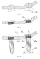
- Fig. 1A illustrates a bone plate with an overpress having a concave portion in relation to the top surface of the plate and the convex portion in relation to the bottom surface of the plate
- Fig. 1B shows a bone plate with a recess in the bottom convex portion of the overpress
- Fig. 1C describes a bone plate with a hole for a bone screw insertion formed in the overpress
- Fig. ID presents the set used to stabilize periarticular and/or shaft fractures of the skeletal system where the screw is angularly positioned in relation to the plate
- Fig. 1A illustrates a bone plate with an overpress having a concave portion in relation to the top surface of the plate and the convex portion in relation to the bottom surface of the plate
- Fig. 1B shows a bone plate with a recess in the bottom convex portion of the overpress
- Fig. 1C describes a bone plate with a hole for a bone screw insertion formed in the overpress
- FIG. 2A depicts a plate with the overpress having a convex portion in relation to the top surface of the plate, and a concave portion with respect to its bottom surface
- Fig. 2B illustrates a bone plate with a hole for a bone screw insertion in the overpress that has a convex portion in relation to the top surface of the plate and a concave portion with respect to its bottom surface
- Fig. 2C shows the set used to stabilize periarticular and/or shaft fractures of the skeletal system where in the angular position of the screw with respect to the plate, the screw head does not protrude above the top surface of the plate and its convex portion
- Fig. 3A describes a bone plate with the convex overpress on its bottom and top part
- Fig. 3A describes a bone plate with the convex overpress on its bottom and top part
- FIG. 3B presents a bone plate with cylindrical or conical recesses in the bottom convex part of the overpress;
- Fig. 3C depicts a bone plate of the set with the hole for screw insertion performed in the overpress;
- Fig. 3D illustrates the set where in the angular position of the screw with respect to the plate, the screw head does not protrude above the top surface of the plate and convex portion of the overpress, and the locking thread of the screw does not extend beyond the bottom convex portion of the overpress and the bottom surface of the plate.
- the set used to stabilize periarticular and/or shaft fractures of the skeletal system consists of a bone plate 1 and bone screw 7.
- Fig. 1D shows a bone plate of the set with a shaped, preferably spherical or oval-shaped overpress that has a concave portion 1A in relation to the top surface 3 of the plate, and a convex portion 2B with respect to the bottom surface 4 of the plate.
- a cylindrical or conical recess 5 is performed in the bottom convex portion 2B of the overpress.
- Fig. 1C shows the overpress with a hole 6 in it for the appropriate bone screw 7 insertion.
- the screw 7 head 8 When the screw 7 is positioned angularly with respect to the plate 1, the screw 7 head 8 does not protrude above the top surface 3 of the plate 1 and the screw 7 locking thread 9 does not protrude beyond the bottom convex portion 2B of the overpress and the bottom surface 4 of the plate 1.
- the depth of the overpress is dependent on the angle ⁇ of inclination of the plate 1 hole 6 axis 10 with respect to the axis 11 perpendicular to the top surface 3 as shown in Fig. 1D .
- the recess 5 performed in the overpress smoothes the edge resulted from the hole 6 performed. Additionally, convex portion 2B of the overpress forces the bottom surface 4 of the plate 1 to be pulled back in relation to the bone surface which results in a greatly reduced plate-bone contact surface which further on preferably influences peri-implant blood circulation and accelerates bone healing. Furthermore, the head 8 of the locking screw 7 works with its entire perimeter with the hole 6.
- Fig. 2A ?? Fig.2C show the embodiment with a shaped, preferably spherical or oval-shaped overpress that has a convex portion 1B with respect to the top surface 3 of the plate 1 and the concave portion 2A in relation to its bottom surface 4.
- a hole 6 for a suitable bone screw insertion was performed and when the screw 7 is positioned angularly in relation to the plate 1, the head 8 of the screw 7 does not protrude above the top surface 3 of the plate 1 and a convex portion 1B of the overpress and the locking thread 9 of the screw 7 do not protrude beyond the bottom surface 4 of the plate 1.
- the depth of the overpress is dependent on the angle ⁇ of inclination of the plate hole 6 axis 10 with respect to the axis 11 perpendicular to its top surface. Furthermore, the head 8 of the screw 7 works with its entire perimeter with the hole 6.
- the bone plate 1 has a shaped, preferably spherical or oval-shaped overpresses that have a convex portion 1B with respect to the top surface 3 of the plate 1, and a convex portion 2B in relation to the bottom surface 4 of the plate 1, as shown in Fig. 3A .
- a cylindrical or conical recess 5 is performed as shown in Fig.
- a hole 6 is performed for appropriate screw insertion.
- the screw 7 head 8 does not protrude above the top surface 1B of the overpress and a convex portion 2B of the overpress, and the locking thread 9 of the screw 7 does not protrude beyond the bottom portion of the convex 2B of the overpress and the bottom surface 4 of the plate 1.
- the depth of the overpress is dependent on the angle ⁇ of inclination of the plate 1 hole 6 axis 10 with respect to the axis 11 perpendicular to the top surface 3 of the plate 1.
- the recess 5 performed in the overpress smoothes the edge resulted from the hole 6 performed.
- convex portion 2B of the overpress forces the bottom surface 4 of the plate 1 to be pulled back in relation to the bone surface which results in a greatly reduced plate-bone contact surface which further on preferably influences peri-implant tissue blood circulation and accelerates bone healing.
- the head 8 of the screw 7 works with its entire perimeter with the hole 6.
Landscapes
- Health & Medical Sciences (AREA)
- Orthopedic Medicine & Surgery (AREA)
- Surgery (AREA)
- Life Sciences & Earth Sciences (AREA)
- Heart & Thoracic Surgery (AREA)
- Nuclear Medicine, Radiotherapy & Molecular Imaging (AREA)
- Engineering & Computer Science (AREA)
- Biomedical Technology (AREA)
- Neurology (AREA)
- Medical Informatics (AREA)
- Molecular Biology (AREA)
- Animal Behavior & Ethology (AREA)
- General Health & Medical Sciences (AREA)
- Public Health (AREA)
- Veterinary Medicine (AREA)
- Surgical Instruments (AREA)
Abstract
Description
- The invention relates to the set of bone plate and bone screw used to stabilize periarticular and/or shaft fractures of the skeletal system.
- In clinical treatment of bone fractures with internal stabilization using bone plates, there are many structural embodiments used for periarticular and/or shaft fractures stabilization based on the use of bone plate and locking screws. In this treatment, the bone union relies on a stable connection of a plate with a locking screw which allows for angular stable fixation of bone fragments, preventing the fragments and bone screws from migration. In orthopedics, the most widely used connection is a threaded connection where a locking screw has a threaded head that cooperates with a threaded hole of a bone plate.
- Complex shapes of locking plates, physiological limitations referring to the plates thickness and angular adjustment of the screws that are forced by a complex anatomy of the human skeleton, pose problems in use of the currently offered structural embodiments, in particular, the heads of the locking screws that protrude above the top or bottom surface of the plate which causes i.a. irritation and compression of peri-implant tissues (tendons, skin, etc.). The problem also relates to a limited number of active thread coils of the locking plate hole, resulting in lower mechanical strength of the screw-plate threaded connection. Moreover, in the current state of the art, there is a limited range of angular positioning of the screw in relation to the plate surface. Overgrowing of the exposed portion of the thread with tissues impedes the subsequent removal of the implant.
- In the current state of the art the above-mentioned problems are solved by:
- making the plate thicker which, however, is not applicable in all types of fracture fixation,
- reducing the height of the screw head, consequently reducing the cooperating surface of the plate-screw construct, thus lowering the mechanical strength of the connection,
- performing conical overpresses applicable to thin bone plates of thickness of 0.5±2mm. This embodiment has a great limitation regarding the angle of the screw inclination in relation to the plate surface - the need to maintain concentricity of the overpress and the axis of the locking hole.
- The current state of the art relating to the set used to stabilize periarticular and/or shaft fractures of the skeletal system is described i.a. in the Patents numbered:
EP1211992 B1 ,EP1211993 B1 ,EP1610700 B1 ,EP2040631B1 ,US6821278B2 and in the Inventions Applications numbered:EP2559394 A1 andUS 2004/0153073 A1 . - The European Patent
EP 1211992 B1 discloses an embodiment where a conical threaded hole is performed in the bone plate of the set that comprises at least one locking screw mounted to the plate in a fixed angular relationship. However, in this embodiment, when larger angles of the locking hole axis inclination occur, the screw will not work with its entire perimeter with the plate hole and the screw head will protrude above the surface of the plate. A part of the locking screw thread will be exposed and the peri-implant tissue overgrowing may occur. - The European Patent
EP 1211993 B1 discloses an embodiment where a hole is performed with an element that gets deformed during screw insertion, without locking thread in the hole of the plate. This allows the insertion of the screw at a different angle, however, threaded screw head works with a locking hole of a plate at a very short distance. In this embodiment, the locking thread is exposed and the peri-implant tissue overgrowing may occur. - The embodiment presented in European Patent
EP1610700 B1 refers to two adjacent threaded locking holes with the possibility to make a hole at an angle. The top recess allows the screw head to immerse. A similar screw embodiment as ChLP screw causes protrusion of the screw at the higher inclination angles and in thin plates. The locking threads are exposed and the peri-implant tissue overgrowing may occur. - The next European Patent -
EP2040631 B 1 discloses an embodiment where a calcaneal plate with local thickened cross-section was presented. This allows for positioning of the screw at a greater angle. The local increase in thickness of the plate is not always possible due to the anatomical and technical limitations of the device. - In the European Invention Application -
EP2559394 A1 - the embodiment described presents a locking hole and screws with the possibility of changing the angle of insertion. Half-thread profiles may weaken screw-plate connection. Although performed upper deepening eliminates the screw head protrusion above the top surface of the plate, this embodiment is limited by the thickness of the plate. When angularly positioned, locking threads of the screw head are exposed and the peri-implant tissue overgrowing may occur. - The American Invention Application
US 2004/0153073 A1 presents locking using threaded end cap. The disadvantage of this embodiment is introduction of an additional locking element. Moreover, the connection strength is lower than in the case of a direct threaded screw-plate connection. - The American Patent
US6821278B2 discloses an embodiment where a plate with conical bends and locking holes in them is presented. This embodiment limits the inclination angle of the screw in relation to the plate surface. It does not eliminate, however, the protrusion of the screw head above the top surface of the plate. - The aim of this invention is the embodiment relating to the set used to stabilize periarticular and/or shaft fractures of the skeletal system wherein the screw head, when angularly positioned in relation to the plate, does not protrude over the top surface of the plate. Furthermore, the locking thread of the screw should not protrude beyond the bottom convex portion of the overpress and the bottom surface of the plate.
- The invention relates to the set of bone plate and bone screw used to stabilize fractures, wherein the angularly positioned locking screw that has a threaded head cooperates with a threaded hole of the bone plate. The set is characterized in that by a plate that in the region of holes for bone screws insertion has shaped, preferably spherical or oval-shaped overpresses that have a concave and a convex portion in relation to the outer surfaces of the plate.
- In an advantageous embodiment, in the convex portion of the overpress, a recess is performed and the depth of the overpress increases with the angle of inclination α of the plate hole axis in relation to the axis perpendicular to the top surface of the plate.
- The embodiment of the set used to stabilize periarticular and/or shaft fractures of the skeletal system eliminates the most common problems in the current state of the art. The shape of the plate surface in the region of holes for bone screws insertion allows for the optimum thickness of the plate without its thickening on the entire length. Applied overpresses do not limit the inclination angle of the screw in relation to the plate surface and do not enforce the need to maintain concentricity of the overpress and the locking hole axis.
- The invention is presented for example on a drawing in which:
Fig. 1A illustrates a bone plate with an overpress having a concave portion in relation to the top surface of the plate and the convex portion in relation to the bottom surface of the plate;Fig. 1B shows a bone plate with a recess in the bottom convex portion of the overpress;Fig. 1C describes a bone plate with a hole for a bone screw insertion formed in the overpress; Fig. ID presents the set used to stabilize periarticular and/or shaft fractures of the skeletal system where the screw is angularly positioned in relation to the plate;Fig. 2A depicts a plate with the overpress having a convex portion in relation to the top surface of the plate, and a concave portion with respect to its bottom surface;Fig. 2B illustrates a bone plate with a hole for a bone screw insertion in the overpress that has a convex portion in relation to the top surface of the plate and a concave portion with respect to its bottom surface;Fig. 2C shows the set used to stabilize periarticular and/or shaft fractures of the skeletal system where in the angular position of the screw with respect to the plate, the screw head does not protrude above the top surface of the plate and its convex portion;Fig. 3A describes a bone plate with the convex overpress on its bottom and top part;Fig. 3B presents a bone plate with cylindrical or conical recesses in the bottom convex part of the overpress;Fig. 3C depicts a bone plate of the set with the hole for screw insertion performed in the overpress;Fig. 3D illustrates the set where in the angular position of the screw with respect to the plate, the screw head does not protrude above the top surface of the plate and convex portion of the overpress, and the locking thread of the screw does not extend beyond the bottom convex portion of the overpress and the bottom surface of the plate. - The set used to stabilize periarticular and/or shaft fractures of the skeletal system consists of a bone plate 1 and
bone screw 7. - In the sets provided below, the appropriate configurations of the plate surface in the region of the
holes 6 forbone screws insertion 7 are introduced. The embodiment shown in the drawing inFig. 1A ÷Fig. 1D shows a bone plate of the set with a shaped, preferably spherical or oval-shaped overpress that has aconcave portion 1A in relation to thetop surface 3 of the plate, and aconvex portion 2B with respect to thebottom surface 4 of the plate. In the bottomconvex portion 2B of the overpress, a cylindrical orconical recess 5 is performed.Fig. 1C shows the overpress with ahole 6 in it for theappropriate bone screw 7 insertion. When thescrew 7 is positioned angularly with respect to the plate 1, thescrew 7head 8 does not protrude above thetop surface 3 of the plate 1 and thescrew 7locking thread 9 does not protrude beyond the bottomconvex portion 2B of the overpress and thebottom surface 4 of the plate 1. The depth of the overpress is dependent on the angle α of inclination of the plate 1hole 6axis 10 with respect to theaxis 11 perpendicular to thetop surface 3 as shown inFig. 1D . - The
recess 5 performed in the overpress smoothes the edge resulted from thehole 6 performed. Additionally,convex portion 2B of the overpress forces thebottom surface 4 of the plate 1 to be pulled back in relation to the bone surface which results in a greatly reduced plate-bone contact surface which further on preferably influences peri-implant blood circulation and accelerates bone healing. Furthermore, thehead 8 of the lockingscrew 7 works with its entire perimeter with thehole 6. -
Fig. 2A ÷Fig.2C show the embodiment with a shaped, preferably spherical or oval-shaped overpress that has aconvex portion 1B with respect to thetop surface 3 of the plate 1 and theconcave portion 2A in relation to itsbottom surface 4. In the overpress, ahole 6 for a suitable bone screw insertion was performed and when thescrew 7 is positioned angularly in relation to the plate 1, thehead 8 of thescrew 7 does not protrude above thetop surface 3 of the plate 1 and aconvex portion 1B of the overpress and the lockingthread 9 of thescrew 7 do not protrude beyond thebottom surface 4 of the plate 1. The depth of the overpress is dependent on the angle α of inclination of theplate hole 6axis 10 with respect to theaxis 11 perpendicular to its top surface. Furthermore, thehead 8 of thescrew 7 works with its entire perimeter with thehole 6. As shown inFig. 3A ÷Fig.3D , the bone plate 1 has a shaped, preferably spherical or oval-shaped overpresses that have aconvex portion 1B with respect to thetop surface 3 of the plate 1, and aconvex portion 2B in relation to thebottom surface 4 of the plate 1, as shown inFig. 3A . Additionally, in the bottom portion of the convex 2B of the overpress, a cylindrical orconical recess 5 is performed as shown inFig. 3B . In that overpress, ahole 6 is performed for appropriate screw insertion. Similarly to two previous embodiments, when thescrew 7 is angularly positioned in relation to the plate 1, thescrew 7head 8 does not protrude above thetop surface 1B of the overpress and aconvex portion 2B of the overpress, and the lockingthread 9 of thescrew 7 does not protrude beyond the bottom portion of the convex 2B of the overpress and thebottom surface 4 of the plate 1. The depth of the overpress is dependent on the angle α of inclination of the plate 1hole 6axis 10 with respect to theaxis 11 perpendicular to thetop surface 3 of the plate 1. Therecess 5 performed in the overpress smoothes the edge resulted from thehole 6 performed. Additionally,convex portion 2B of the overpress forces thebottom surface 4 of the plate 1 to be pulled back in relation to the bone surface which results in a greatly reduced plate-bone contact surface which further on preferably influences peri-implant tissue blood circulation and accelerates bone healing. Furthermore, thehead 8 of thescrew 7 works with its entire perimeter with thehole 6.
Claims (3)
- The set of bone plate and bone screw used to stabilize fractures wherein the angularly positioned locking screw that has a threaded head cooperates with a threaded hole of the bone plate characterized in that the top surface (3) of the plate (1) in the area of holes (6) for bone screws (7) insertion has at least one shaped overpress, preferably spherical or oval-shaped which has a concave (1A) or convex (1B) portion in relation to the top surface (3) of the plate (1) and a concave (2A) or a convex (2B) portion with respect to the bottom surface 4 of the plate (1).
- The set acc. to claim 1 characterized in that in the convex (2B) portion of the overpress a recess (5) is performed.
- The set acc. to claim 1 characterized in that the depth (G) of the overpress increases with the angle of inclination α of the plate (1) hole (6) axis (10) in relation to the axis (11) perpendicular to the top surface (3) of the plate (1).
Priority Applications (1)
| Application Number | Priority Date | Filing Date | Title |
|---|---|---|---|
| PL15460064T PL2995270T3 (en) | 2014-09-12 | 2015-09-03 | The set of bone plate and bone screw used to stabilize fractures |
Applications Claiming Priority (1)
| Application Number | Priority Date | Filing Date | Title |
|---|---|---|---|
| PL409476A PL231693B1 (en) | 2014-09-12 | 2014-09-12 | Bone plate complex with the bone screw for stabilization of fractures |
Publications (2)
| Publication Number | Publication Date |
|---|---|
| EP2995270A1 true EP2995270A1 (en) | 2016-03-16 |
| EP2995270B1 EP2995270B1 (en) | 2018-02-14 |
Family
ID=54148453
Family Applications (1)
| Application Number | Title | Priority Date | Filing Date |
|---|---|---|---|
| EP15460064.7A Active EP2995270B1 (en) | 2014-09-12 | 2015-09-03 | The set of bone plate and bone screw used to stabilize fractures |
Country Status (6)
| Country | Link |
|---|---|
| EP (1) | EP2995270B1 (en) |
| ES (1) | ES2668856T3 (en) |
| PL (2) | PL231693B1 (en) |
| PT (1) | PT2995270T (en) |
| RU (1) | RU2604035C2 (en) |
| TR (1) | TR201806816T4 (en) |
Cited By (2)
| Publication number | Priority date | Publication date | Assignee | Title |
|---|---|---|---|---|
| CN112437639A (en) * | 2018-06-12 | 2021-03-02 | 奥林巴斯泰尓茂生物材料株式会社 | Bone plate and bone plate kit |
| CN115701946A (en) * | 2020-06-11 | 2023-02-14 | 奥林巴斯泰尔茂生物材料株式会社 | bone plate |
Citations (12)
| Publication number | Priority date | Publication date | Assignee | Title |
|---|---|---|---|---|
| JPH01300945A (en) * | 1988-05-30 | 1989-12-05 | Shigeyasu Ito | Broken bone bonding method |
| US20020058940A1 (en) * | 2000-06-26 | 2002-05-16 | Robert Frigg | Bone plate |
| EP1211992B1 (en) | 1999-09-13 | 2004-01-14 | Synthes AG Chur | Bone plate system |
| US20040153073A1 (en) | 2000-02-01 | 2004-08-05 | Hand Innovations, Inc. | Orthopedic fixation system including plate element with threaded holes having divergent axes |
| EP1211993B1 (en) | 1999-09-14 | 2005-10-26 | Dietmar Prof. Dr. Wolter | Fixation system for bones |
| US20080200955A1 (en) * | 2005-02-22 | 2008-08-21 | Kyon | Plate and Screws for Treatment of Bone Fractures |
| US20100016858A1 (en) * | 2008-07-21 | 2010-01-21 | Gerlinde Michel | Carbon Fiber Reinforced Peek Bone Plate With Titanium Fixation Screws |
| EP1610700B1 (en) | 2003-03-26 | 2010-08-04 | Swiss Orthopedic Solutions SA | Locking bone plate |
| EP2040631B1 (en) | 2006-07-18 | 2011-10-12 | Orthohelix Surgical Designs, Inc. | Calcaneal plate |
| EP2559394A1 (en) | 2007-08-13 | 2013-02-20 | Synthes GmbH | Highly-versatile variable-angle bone plate system |
| US20130150853A1 (en) * | 2011-12-12 | 2013-06-13 | Douglas K. Blacklidge | Metatarsal Fixation Device, System and Method |
| US20130211461A1 (en) * | 2012-02-13 | 2013-08-15 | Stryker Trauma Sa | Attachment device for a bone plate |
Family Cites Families (2)
| Publication number | Priority date | Publication date | Assignee | Title |
|---|---|---|---|---|
| RU2190980C1 (en) * | 2001-03-16 | 2002-10-20 | Государственное унитарное предприятие Научное конструкторско-технологическое бюро "Искра" | Plate implant for performing osteosynthesis |
| RU2476180C2 (en) * | 2011-05-05 | 2013-02-27 | Владимир Васильевич Хоминец | Device for osteosynthesis of bone fractures |
-
2014
- 2014-09-12 PL PL409476A patent/PL231693B1/en unknown
-
2015
- 2015-05-06 RU RU2015117224/14A patent/RU2604035C2/en active
- 2015-09-03 ES ES15460064.7T patent/ES2668856T3/en active Active
- 2015-09-03 PT PT154600647T patent/PT2995270T/en unknown
- 2015-09-03 TR TR2018/06816T patent/TR201806816T4/en unknown
- 2015-09-03 PL PL15460064T patent/PL2995270T3/en unknown
- 2015-09-03 EP EP15460064.7A patent/EP2995270B1/en active Active
Patent Citations (13)
| Publication number | Priority date | Publication date | Assignee | Title |
|---|---|---|---|---|
| JPH01300945A (en) * | 1988-05-30 | 1989-12-05 | Shigeyasu Ito | Broken bone bonding method |
| EP1211992B1 (en) | 1999-09-13 | 2004-01-14 | Synthes AG Chur | Bone plate system |
| EP1211993B1 (en) | 1999-09-14 | 2005-10-26 | Dietmar Prof. Dr. Wolter | Fixation system for bones |
| US20040153073A1 (en) | 2000-02-01 | 2004-08-05 | Hand Innovations, Inc. | Orthopedic fixation system including plate element with threaded holes having divergent axes |
| US20020058940A1 (en) * | 2000-06-26 | 2002-05-16 | Robert Frigg | Bone plate |
| US6821278B2 (en) | 2000-06-26 | 2004-11-23 | Synthes Ag Chur | Bone plate |
| EP1610700B1 (en) | 2003-03-26 | 2010-08-04 | Swiss Orthopedic Solutions SA | Locking bone plate |
| US20080200955A1 (en) * | 2005-02-22 | 2008-08-21 | Kyon | Plate and Screws for Treatment of Bone Fractures |
| EP2040631B1 (en) | 2006-07-18 | 2011-10-12 | Orthohelix Surgical Designs, Inc. | Calcaneal plate |
| EP2559394A1 (en) | 2007-08-13 | 2013-02-20 | Synthes GmbH | Highly-versatile variable-angle bone plate system |
| US20100016858A1 (en) * | 2008-07-21 | 2010-01-21 | Gerlinde Michel | Carbon Fiber Reinforced Peek Bone Plate With Titanium Fixation Screws |
| US20130150853A1 (en) * | 2011-12-12 | 2013-06-13 | Douglas K. Blacklidge | Metatarsal Fixation Device, System and Method |
| US20130211461A1 (en) * | 2012-02-13 | 2013-08-15 | Stryker Trauma Sa | Attachment device for a bone plate |
Cited By (4)
| Publication number | Priority date | Publication date | Assignee | Title |
|---|---|---|---|---|
| CN112437639A (en) * | 2018-06-12 | 2021-03-02 | 奥林巴斯泰尓茂生物材料株式会社 | Bone plate and bone plate kit |
| CN115701946A (en) * | 2020-06-11 | 2023-02-14 | 奥林巴斯泰尔茂生物材料株式会社 | bone plate |
| CN115701946B (en) * | 2020-06-11 | 2025-11-14 | 奥林巴斯泰尔茂生物材料株式会社 | Bone plate |
| US12478414B2 (en) | 2020-06-11 | 2025-11-25 | Olympus Terumo Biomaterials Corp. | Bone plate |
Also Published As
| Publication number | Publication date |
|---|---|
| PL2995270T3 (en) | 2018-10-31 |
| RU2015117224A (en) | 2016-11-27 |
| PT2995270T (en) | 2018-05-17 |
| ES2668856T3 (en) | 2018-05-22 |
| EP2995270B1 (en) | 2018-02-14 |
| PL409476A1 (en) | 2016-03-14 |
| PL231693B1 (en) | 2019-03-29 |
| TR201806816T4 (en) | 2018-06-21 |
| RU2604035C2 (en) | 2016-12-10 |
Similar Documents
| Publication | Publication Date | Title |
|---|---|---|
| EP2389884B1 (en) | Implant for bone fixation | |
| EP3202348B1 (en) | Bone plate with alternating chamfers | |
| CA2647067C (en) | Bone stabilization system including multi-directional threaded fixation element | |
| AU775910B2 (en) | Bone plate | |
| US12201334B2 (en) | Femur plate | |
| EP1764052A1 (en) | Bone stabilization system | |
| US20160051295A1 (en) | Osteosynthesis device | |
| JP6847096B2 (en) | Bone fixation implant system | |
| CN111839704A (en) | Degradable Absorbable Magnesium Alloy Rib Fracture Fixation Plate and Fixation Instrument System | |
| CN108852488A (en) | A kind of medical internal fixing peg for fracture and medical fracture setting tool | |
| EP2995270A1 (en) | The set of bone plate and bone screw used to stabilize fractures | |
| US20180256225A1 (en) | Set of bone plate and bone screw used to stabilize fractures | |
| CN103654934A (en) | Combined type locking screw applied to bone plate and bone plate system comprising same | |
| CN209864014U (en) | Inboard supporting steel plate of thighbone neck | |
| JP2019520134A (en) | Bone plate for epiphyseal line closure | |
| KR20200062405A (en) | Distal radius fixation system | |
| CN216221619U (en) | Tibia far-end front locking plate | |
| CN222533372U (en) | Hammer toe screw anti-rotation system | |
| JP2018015432A (en) | Femoral fracture treatment instrument and fixation plate | |
| JP2013094628A (en) | External fixation pin | |
| CN110215268A (en) | Steel plate screw system for osteotomy of calcaneus art | |
| PL151415B1 (en) | Stabilizer for treatment of neck fractures and region of the upper metaphysis of the thigh bone |
Legal Events
| Date | Code | Title | Description |
|---|---|---|---|
| PUAI | Public reference made under article 153(3) epc to a published international application that has entered the european phase |
Free format text: ORIGINAL CODE: 0009012 |
|
| AK | Designated contracting states |
Kind code of ref document: A1 Designated state(s): AL AT BE BG CH CY CZ DE DK EE ES FI FR GB GR HR HU IE IS IT LI LT LU LV MC MK MT NL NO PL PT RO RS SE SI SK SM TR |
|
| AX | Request for extension of the european patent |
Extension state: BA ME |
|
| 17P | Request for examination filed |
Effective date: 20160826 |
|
| RBV | Designated contracting states (corrected) |
Designated state(s): AL AT BE BG CH CY CZ DE DK EE ES FI FR GB GR HR HU IE IS IT LI LT LU LV MC MK MT NL NO PL PT RO RS SE SI SK SM TR |
|
| 17Q | First examination report despatched |
Effective date: 20161109 |
|
| GRAP | Despatch of communication of intention to grant a patent |
Free format text: ORIGINAL CODE: EPIDOSNIGR1 |
|
| GRAJ | Information related to disapproval of communication of intention to grant by the applicant or resumption of examination proceedings by the epo deleted |
Free format text: ORIGINAL CODE: EPIDOSDIGR1 |
|
| GRAP | Despatch of communication of intention to grant a patent |
Free format text: ORIGINAL CODE: EPIDOSNIGR1 |
|
| GRAP | Despatch of communication of intention to grant a patent |
Free format text: ORIGINAL CODE: EPIDOSNIGR1 |
|
| INTG | Intention to grant announced |
Effective date: 20171027 |
|
| INTC | Intention to grant announced (deleted) | ||
| INTG | Intention to grant announced |
Effective date: 20171115 |
|
| GRAS | Grant fee paid |
Free format text: ORIGINAL CODE: EPIDOSNIGR3 |
|
| GRAA | (expected) grant |
Free format text: ORIGINAL CODE: 0009210 |
|
| AK | Designated contracting states |
Kind code of ref document: B1 Designated state(s): AL AT BE BG CH CY CZ DE DK EE ES FI FR GB GR HR HU IE IS IT LI LT LU LV MC MK MT NL NO PL PT RO RS SE SI SK SM TR |
|
| REG | Reference to a national code |
Ref country code: GB Ref legal event code: FG4D |
|
| REG | Reference to a national code |
Ref country code: CH Ref legal event code: EP |
|
| REG | Reference to a national code |
Ref country code: IE Ref legal event code: FG4D |
|
| REG | Reference to a national code |
Ref country code: DE Ref legal event code: R096 Ref document number: 602015008025 Country of ref document: DE Ref country code: AT Ref legal event code: REF Ref document number: 969360 Country of ref document: AT Kind code of ref document: T Effective date: 20180315 |
|
| REG | Reference to a national code |
Ref country code: RO Ref legal event code: EPE |
|
| REG | Reference to a national code |
Ref country code: PT Ref legal event code: SC4A Ref document number: 2995270 Country of ref document: PT Date of ref document: 20180517 Kind code of ref document: T Free format text: AVAILABILITY OF NATIONAL TRANSLATION Effective date: 20180511 |
|
| REG | Reference to a national code |
Ref country code: ES Ref legal event code: FG2A Ref document number: 2668856 Country of ref document: ES Kind code of ref document: T3 Effective date: 20180522 |
|
| REG | Reference to a national code |
Ref country code: NL Ref legal event code: MP Effective date: 20180214 |
|
| REG | Reference to a national code |
Ref country code: AT Ref legal event code: MK05 Ref document number: 969360 Country of ref document: AT Kind code of ref document: T Effective date: 20180214 |
|
| PG25 | Lapsed in a contracting state [announced via postgrant information from national office to epo] |
Ref country code: NL Free format text: LAPSE BECAUSE OF FAILURE TO SUBMIT A TRANSLATION OF THE DESCRIPTION OR TO PAY THE FEE WITHIN THE PRESCRIBED TIME-LIMIT Effective date: 20180214 Ref country code: CY Free format text: LAPSE BECAUSE OF FAILURE TO SUBMIT A TRANSLATION OF THE DESCRIPTION OR TO PAY THE FEE WITHIN THE PRESCRIBED TIME-LIMIT Effective date: 20180214 Ref country code: FI Free format text: LAPSE BECAUSE OF FAILURE TO SUBMIT A TRANSLATION OF THE DESCRIPTION OR TO PAY THE FEE WITHIN THE PRESCRIBED TIME-LIMIT Effective date: 20180214 Ref country code: LT Free format text: LAPSE BECAUSE OF FAILURE TO SUBMIT A TRANSLATION OF THE DESCRIPTION OR TO PAY THE FEE WITHIN THE PRESCRIBED TIME-LIMIT Effective date: 20180214 Ref country code: HR Free format text: LAPSE BECAUSE OF FAILURE TO SUBMIT A TRANSLATION OF THE DESCRIPTION OR TO PAY THE FEE WITHIN THE PRESCRIBED TIME-LIMIT Effective date: 20180214 Ref country code: NO Free format text: LAPSE BECAUSE OF FAILURE TO SUBMIT A TRANSLATION OF THE DESCRIPTION OR TO PAY THE FEE WITHIN THE PRESCRIBED TIME-LIMIT Effective date: 20180514 |
|
| PG25 | Lapsed in a contracting state [announced via postgrant information from national office to epo] |
Ref country code: AT Free format text: LAPSE BECAUSE OF FAILURE TO SUBMIT A TRANSLATION OF THE DESCRIPTION OR TO PAY THE FEE WITHIN THE PRESCRIBED TIME-LIMIT Effective date: 20180214 Ref country code: RS Free format text: LAPSE BECAUSE OF FAILURE TO SUBMIT A TRANSLATION OF THE DESCRIPTION OR TO PAY THE FEE WITHIN THE PRESCRIBED TIME-LIMIT Effective date: 20180214 Ref country code: BG Free format text: LAPSE BECAUSE OF FAILURE TO SUBMIT A TRANSLATION OF THE DESCRIPTION OR TO PAY THE FEE WITHIN THE PRESCRIBED TIME-LIMIT Effective date: 20180514 Ref country code: LV Free format text: LAPSE BECAUSE OF FAILURE TO SUBMIT A TRANSLATION OF THE DESCRIPTION OR TO PAY THE FEE WITHIN THE PRESCRIBED TIME-LIMIT Effective date: 20180214 Ref country code: SE Free format text: LAPSE BECAUSE OF FAILURE TO SUBMIT A TRANSLATION OF THE DESCRIPTION OR TO PAY THE FEE WITHIN THE PRESCRIBED TIME-LIMIT Effective date: 20180214 |
|
| PG25 | Lapsed in a contracting state [announced via postgrant information from national office to epo] |
Ref country code: AL Free format text: LAPSE BECAUSE OF FAILURE TO SUBMIT A TRANSLATION OF THE DESCRIPTION OR TO PAY THE FEE WITHIN THE PRESCRIBED TIME-LIMIT Effective date: 20180214 Ref country code: EE Free format text: LAPSE BECAUSE OF FAILURE TO SUBMIT A TRANSLATION OF THE DESCRIPTION OR TO PAY THE FEE WITHIN THE PRESCRIBED TIME-LIMIT Effective date: 20180214 |
|
| REG | Reference to a national code |
Ref country code: GR Ref legal event code: EP Ref document number: 20180401158 Country of ref document: GR Effective date: 20181012 |
|
| REG | Reference to a national code |
Ref country code: DE Ref legal event code: R097 Ref document number: 602015008025 Country of ref document: DE |
|
| PG25 | Lapsed in a contracting state [announced via postgrant information from national office to epo] |
Ref country code: DK Free format text: LAPSE BECAUSE OF FAILURE TO SUBMIT A TRANSLATION OF THE DESCRIPTION OR TO PAY THE FEE WITHIN THE PRESCRIBED TIME-LIMIT Effective date: 20180214 Ref country code: SM Free format text: LAPSE BECAUSE OF FAILURE TO SUBMIT A TRANSLATION OF THE DESCRIPTION OR TO PAY THE FEE WITHIN THE PRESCRIBED TIME-LIMIT Effective date: 20180214 Ref country code: CZ Free format text: LAPSE BECAUSE OF FAILURE TO SUBMIT A TRANSLATION OF THE DESCRIPTION OR TO PAY THE FEE WITHIN THE PRESCRIBED TIME-LIMIT Effective date: 20180214 Ref country code: SK Free format text: LAPSE BECAUSE OF FAILURE TO SUBMIT A TRANSLATION OF THE DESCRIPTION OR TO PAY THE FEE WITHIN THE PRESCRIBED TIME-LIMIT Effective date: 20180214 |
|
| PLBE | No opposition filed within time limit |
Free format text: ORIGINAL CODE: 0009261 |
|
| STAA | Information on the status of an ep patent application or granted ep patent |
Free format text: STATUS: NO OPPOSITION FILED WITHIN TIME LIMIT |
|
| 26N | No opposition filed |
Effective date: 20181115 |
|
| PG25 | Lapsed in a contracting state [announced via postgrant information from national office to epo] |
Ref country code: SI Free format text: LAPSE BECAUSE OF FAILURE TO SUBMIT A TRANSLATION OF THE DESCRIPTION OR TO PAY THE FEE WITHIN THE PRESCRIBED TIME-LIMIT Effective date: 20180214 |
|
| PG25 | Lapsed in a contracting state [announced via postgrant information from national office to epo] |
Ref country code: MC Free format text: LAPSE BECAUSE OF FAILURE TO SUBMIT A TRANSLATION OF THE DESCRIPTION OR TO PAY THE FEE WITHIN THE PRESCRIBED TIME-LIMIT Effective date: 20180214 |
|
| REG | Reference to a national code |
Ref country code: CH Ref legal event code: PL |
|
| REG | Reference to a national code |
Ref country code: BE Ref legal event code: MM Effective date: 20180930 |
|
| REG | Reference to a national code |
Ref country code: IE Ref legal event code: MM4A |
|
| PG25 | Lapsed in a contracting state [announced via postgrant information from national office to epo] |
Ref country code: LU Free format text: LAPSE BECAUSE OF NON-PAYMENT OF DUE FEES Effective date: 20180903 |
|
| PG25 | Lapsed in a contracting state [announced via postgrant information from national office to epo] |
Ref country code: IE Free format text: LAPSE BECAUSE OF NON-PAYMENT OF DUE FEES Effective date: 20180903 |
|
| PG25 | Lapsed in a contracting state [announced via postgrant information from national office to epo] |
Ref country code: FR Free format text: LAPSE BECAUSE OF NON-PAYMENT OF DUE FEES Effective date: 20180930 Ref country code: LI Free format text: LAPSE BECAUSE OF NON-PAYMENT OF DUE FEES Effective date: 20180930 Ref country code: CH Free format text: LAPSE BECAUSE OF NON-PAYMENT OF DUE FEES Effective date: 20180930 Ref country code: BE Free format text: LAPSE BECAUSE OF NON-PAYMENT OF DUE FEES Effective date: 20180930 |
|
| PG25 | Lapsed in a contracting state [announced via postgrant information from national office to epo] |
Ref country code: MT Free format text: LAPSE BECAUSE OF NON-PAYMENT OF DUE FEES Effective date: 20180903 |
|
| PG25 | Lapsed in a contracting state [announced via postgrant information from national office to epo] |
Ref country code: HU Free format text: LAPSE BECAUSE OF FAILURE TO SUBMIT A TRANSLATION OF THE DESCRIPTION OR TO PAY THE FEE WITHIN THE PRESCRIBED TIME-LIMIT; INVALID AB INITIO Effective date: 20150903 Ref country code: MK Free format text: LAPSE BECAUSE OF NON-PAYMENT OF DUE FEES Effective date: 20180214 |
|
| PG25 | Lapsed in a contracting state [announced via postgrant information from national office to epo] |
Ref country code: IS Free format text: LAPSE BECAUSE OF FAILURE TO SUBMIT A TRANSLATION OF THE DESCRIPTION OR TO PAY THE FEE WITHIN THE PRESCRIBED TIME-LIMIT Effective date: 20180614 |
|
| PGFP | Annual fee paid to national office [announced via postgrant information from national office to epo] |
Ref country code: PT Payment date: 20250618 Year of fee payment: 11 |
|
| PGFP | Annual fee paid to national office [announced via postgrant information from national office to epo] |
Ref country code: GR Payment date: 20250618 Year of fee payment: 11 |
|
| PGFP | Annual fee paid to national office [announced via postgrant information from national office to epo] |
Ref country code: DE Payment date: 20250922 Year of fee payment: 11 |
|
| PGFP | Annual fee paid to national office [announced via postgrant information from national office to epo] |
Ref country code: TR Payment date: 20250902 Year of fee payment: 11 Ref country code: IT Payment date: 20250805 Year of fee payment: 11 Ref country code: PL Payment date: 20250826 Year of fee payment: 11 |
|
| PGFP | Annual fee paid to national office [announced via postgrant information from national office to epo] |
Ref country code: GB Payment date: 20250703 Year of fee payment: 11 |
|
| PGFP | Annual fee paid to national office [announced via postgrant information from national office to epo] |
Ref country code: ES Payment date: 20251103 Year of fee payment: 11 |
|
| PGFP | Annual fee paid to national office [announced via postgrant information from national office to epo] |
Ref country code: RO Payment date: 20260227 Year of fee payment: 11 |