EP2995284B1 - Befestigungsmodul und bewegungsunterstützungsvorrichtung damit - Google Patents
Befestigungsmodul und bewegungsunterstützungsvorrichtung damit Download PDFInfo
- Publication number
- EP2995284B1 EP2995284B1 EP15152670.4A EP15152670A EP2995284B1 EP 2995284 B1 EP2995284 B1 EP 2995284B1 EP 15152670 A EP15152670 A EP 15152670A EP 2995284 B1 EP2995284 B1 EP 2995284B1
- Authority
- EP
- European Patent Office
- Prior art keywords
- supporting member
- user
- extending portion
- frame
- fixing device
- Prior art date
- Legal status (The legal status is an assumption and is not a legal conclusion. Google has not performed a legal analysis and makes no representation as to the accuracy of the status listed.)
- Active
Links
Images






Classifications
-
- A—HUMAN NECESSITIES
- A61—MEDICAL OR VETERINARY SCIENCE; HYGIENE
- A61H—PHYSICAL THERAPY APPARATUS, e.g. DEVICES FOR LOCATING OR STIMULATING REFLEX POINTS IN THE BODY; ARTIFICIAL RESPIRATION; MASSAGE; BATHING DEVICES FOR SPECIAL THERAPEUTIC OR HYGIENIC PURPOSES OR SPECIFIC PARTS OF THE BODY
- A61H3/00—Appliances for aiding patients or disabled persons to walk about
- A61H3/008—Appliances for aiding patients or disabled persons to walk about using suspension devices for supporting the body in an upright walking or standing position, e.g. harnesses
-
- A—HUMAN NECESSITIES
- A61—MEDICAL OR VETERINARY SCIENCE; HYGIENE
- A61F—FILTERS IMPLANTABLE INTO BLOOD VESSELS; PROSTHESES; DEVICES PROVIDING PATENCY TO, OR PREVENTING COLLAPSING OF, TUBULAR STRUCTURES OF THE BODY, e.g. STENTS; ORTHOPAEDIC, NURSING OR CONTRACEPTIVE DEVICES; FOMENTATION; TREATMENT OR PROTECTION OF EYES OR EARS; BANDAGES, DRESSINGS OR ABSORBENT PADS; FIRST-AID KITS
- A61F5/00—Orthopaedic methods or devices for non-surgical treatment of bones or joints; Nursing devices ; Anti-rape devices
- A61F5/01—Orthopaedic devices, e.g. long-term immobilising or pressure directing devices for treating broken or deformed bones such as splints, casts or braces
- A61F5/0193—Apparatus specially adapted for treating hip dislocation; Abduction splints
-
- A—HUMAN NECESSITIES
- A61—MEDICAL OR VETERINARY SCIENCE; HYGIENE
- A61F—FILTERS IMPLANTABLE INTO BLOOD VESSELS; PROSTHESES; DEVICES PROVIDING PATENCY TO, OR PREVENTING COLLAPSING OF, TUBULAR STRUCTURES OF THE BODY, e.g. STENTS; ORTHOPAEDIC, NURSING OR CONTRACEPTIVE DEVICES; FOMENTATION; TREATMENT OR PROTECTION OF EYES OR EARS; BANDAGES, DRESSINGS OR ABSORBENT PADS; FIRST-AID KITS
- A61F5/00—Orthopaedic methods or devices for non-surgical treatment of bones or joints; Nursing devices ; Anti-rape devices
- A61F5/01—Orthopaedic devices, e.g. long-term immobilising or pressure directing devices for treating broken or deformed bones such as splints, casts or braces
- A61F5/02—Orthopaedic corsets
-
- A—HUMAN NECESSITIES
- A61—MEDICAL OR VETERINARY SCIENCE; HYGIENE
- A61F—FILTERS IMPLANTABLE INTO BLOOD VESSELS; PROSTHESES; DEVICES PROVIDING PATENCY TO, OR PREVENTING COLLAPSING OF, TUBULAR STRUCTURES OF THE BODY, e.g. STENTS; ORTHOPAEDIC, NURSING OR CONTRACEPTIVE DEVICES; FOMENTATION; TREATMENT OR PROTECTION OF EYES OR EARS; BANDAGES, DRESSINGS OR ABSORBENT PADS; FIRST-AID KITS
- A61F5/00—Orthopaedic methods or devices for non-surgical treatment of bones or joints; Nursing devices ; Anti-rape devices
- A61F5/01—Orthopaedic devices, e.g. long-term immobilising or pressure directing devices for treating broken or deformed bones such as splints, casts or braces
- A61F5/02—Orthopaedic corsets
- A61F5/022—Orthopaedic corsets consisting of one or more shells
-
- A—HUMAN NECESSITIES
- A61—MEDICAL OR VETERINARY SCIENCE; HYGIENE
- A61F—FILTERS IMPLANTABLE INTO BLOOD VESSELS; PROSTHESES; DEVICES PROVIDING PATENCY TO, OR PREVENTING COLLAPSING OF, TUBULAR STRUCTURES OF THE BODY, e.g. STENTS; ORTHOPAEDIC, NURSING OR CONTRACEPTIVE DEVICES; FOMENTATION; TREATMENT OR PROTECTION OF EYES OR EARS; BANDAGES, DRESSINGS OR ABSORBENT PADS; FIRST-AID KITS
- A61F5/00—Orthopaedic methods or devices for non-surgical treatment of bones or joints; Nursing devices ; Anti-rape devices
- A61F5/01—Orthopaedic devices, e.g. long-term immobilising or pressure directing devices for treating broken or deformed bones such as splints, casts or braces
- A61F5/02—Orthopaedic corsets
- A61F5/028—Braces for providing support to the lower back, e.g. lumbo sacral supports
-
- A—HUMAN NECESSITIES
- A61—MEDICAL OR VETERINARY SCIENCE; HYGIENE
- A61H—PHYSICAL THERAPY APPARATUS, e.g. DEVICES FOR LOCATING OR STIMULATING REFLEX POINTS IN THE BODY; ARTIFICIAL RESPIRATION; MASSAGE; BATHING DEVICES FOR SPECIAL THERAPEUTIC OR HYGIENIC PURPOSES OR SPECIFIC PARTS OF THE BODY
- A61H1/00—Apparatus for passive exercising; Vibrating apparatus; Chiropractic devices, e.g. body impacting devices, external devices for briefly extending or aligning unbroken bones
- A61H1/02—Stretching or bending or torsioning apparatus for exercising
- A61H1/0237—Stretching or bending or torsioning apparatus for exercising for the lower limbs
- A61H1/0244—Hip
-
- B—PERFORMING OPERATIONS; TRANSPORTING
- B25—HAND TOOLS; PORTABLE POWER-DRIVEN TOOLS; MANIPULATORS
- B25J—MANIPULATORS; CHAMBERS PROVIDED WITH MANIPULATION DEVICES
- B25J9/00—Program-controlled manipulators
- B25J9/0006—Exoskeletons, i.e. resembling a human figure
-
- A—HUMAN NECESSITIES
- A61—MEDICAL OR VETERINARY SCIENCE; HYGIENE
- A61F—FILTERS IMPLANTABLE INTO BLOOD VESSELS; PROSTHESES; DEVICES PROVIDING PATENCY TO, OR PREVENTING COLLAPSING OF, TUBULAR STRUCTURES OF THE BODY, e.g. STENTS; ORTHOPAEDIC, NURSING OR CONTRACEPTIVE DEVICES; FOMENTATION; TREATMENT OR PROTECTION OF EYES OR EARS; BANDAGES, DRESSINGS OR ABSORBENT PADS; FIRST-AID KITS
- A61F5/00—Orthopaedic methods or devices for non-surgical treatment of bones or joints; Nursing devices ; Anti-rape devices
- A61F5/01—Orthopaedic devices, e.g. long-term immobilising or pressure directing devices for treating broken or deformed bones such as splints, casts or braces
- A61F5/0102—Orthopaedic devices, e.g. long-term immobilising or pressure directing devices for treating broken or deformed bones such as splints, casts or braces specially adapted for correcting deformities of the limbs or for supporting them; Ortheses, e.g. with articulations
- A61F2005/0132—Additional features of the articulation
- A61F2005/0137—Additional features of the articulation with two parallel pivots
-
- A—HUMAN NECESSITIES
- A61—MEDICAL OR VETERINARY SCIENCE; HYGIENE
- A61F—FILTERS IMPLANTABLE INTO BLOOD VESSELS; PROSTHESES; DEVICES PROVIDING PATENCY TO, OR PREVENTING COLLAPSING OF, TUBULAR STRUCTURES OF THE BODY, e.g. STENTS; ORTHOPAEDIC, NURSING OR CONTRACEPTIVE DEVICES; FOMENTATION; TREATMENT OR PROTECTION OF EYES OR EARS; BANDAGES, DRESSINGS OR ABSORBENT PADS; FIRST-AID KITS
- A61F5/00—Orthopaedic methods or devices for non-surgical treatment of bones or joints; Nursing devices ; Anti-rape devices
- A61F5/01—Orthopaedic devices, e.g. long-term immobilising or pressure directing devices for treating broken or deformed bones such as splints, casts or braces
- A61F5/0102—Orthopaedic devices, e.g. long-term immobilising or pressure directing devices for treating broken or deformed bones such as splints, casts or braces specially adapted for correcting deformities of the limbs or for supporting them; Ortheses, e.g. with articulations
- A61F2005/0132—Additional features of the articulation
- A61F2005/0155—Additional features of the articulation with actuating means
-
- A—HUMAN NECESSITIES
- A61—MEDICAL OR VETERINARY SCIENCE; HYGIENE
- A61H—PHYSICAL THERAPY APPARATUS, e.g. DEVICES FOR LOCATING OR STIMULATING REFLEX POINTS IN THE BODY; ARTIFICIAL RESPIRATION; MASSAGE; BATHING DEVICES FOR SPECIAL THERAPEUTIC OR HYGIENIC PURPOSES OR SPECIFIC PARTS OF THE BODY
- A61H3/00—Appliances for aiding patients or disabled persons to walk about
- A61H2003/007—Appliances for aiding patients or disabled persons to walk about secured to the patient, e.g. with belts
Definitions
- Example embodiments relate to a fixing module and/or a motion assistance apparatus including the same.
- the motion assistance apparatuses may include active joint structures including hydraulic systems and/or driving motors to drive each joint portion to improve muscular strength of legs of users.
- a motion assistance apparatus may come in various fixed sizes according to a waist of the user.
- a motion assistance apparatus may shake due to torsional forces applied thereto while assisting the user with walking.
- US2012/316476A1 discloses a walking assistance device having an abdominal belt system that secures a pelvic frame on the pelvic part of a user.
- the abdominal belt includes a pair of side belt parts extending forward along an inner side of the pelvic frame from a rear part thereof and a front belt part connecting front ends of the side belt parts.
- WO2012/125765A2 discloses an orthosis including a belt assembly, an energy storage apparatus, and an articulable leg frame.
- the belt assembly is configured to be secured to a user's body.
- the energy storage apparatus is coupled to the belt assembly and includes a pretension adjustment device and an exotendon.
- the articulable leg frame is coupleable to the belt assembly. The energy storage apparatus helps move the user's leg which is coupled to the leg frame.
- a fixing device as defined in any of the claims 1-8. is provided.
- a motion assistance apparatus as defined in any of the claims 9-14 is provided.
- first, second, third, etc. may be used herein to describe various elements, components, regions, layers, and/or sections, these elements, components, regions, layers, and/or sections should not be limited by these terms. These terms are only used to distinguish one element, component, region, layer, and/or section from another element, component, region, layer, and/or section. For example, a first element, component, region, layer, and/or section could be termed a second element, component, region, layer, and/or section without departing from the teachings of example embodiments.
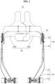
- FIG. 1 is a front view illustrating a motion assistance apparatus according to some example embodiments
- FIG. 2 is a side view illustrating the motion assistance apparatus according to some example embodiments.
- a motion assistance apparatus 10 may be worn by a user to assist a motion of the user.
- the user may correspond to a human, an animal, or a robot. However, the user is not limited thereto.
- FIG. 1 illustrates a case in which the motion assistance apparatus 10 assists motions of thighs of the user
- the motion assistance apparatus 10 may also assist a motion of an upper body, for example, a hand, an upper arm, and a lower arm of the user.
- the motion assistance apparatus 10 may assist a motion of another part of a lower body, for example, a foot, and a calf of the user.
- the motion assistance apparatus 10 may assist a motion of a part of the user.
- the motion assistance apparatus 10 may include a fixing module 20, a driving module 30, a joint assembly 40, and a supporting module 50.
- the fixing module 20 may be fixed to the user.
- the fixing module 20 may be provided in a form of covering an outer surface of the user.
- the fixing module 20 may be fixed to the sides of a waist of the user, and include a curved surface corresponding to a contact portion of the user.
- the fixing module 20 includes a first side frame 100 disposed on one side of the waist of the user, and a second side frame 200 disposed on another side of the waist of the user.
- the driving module 30 may provide power that is transmitted to the joint assembly 40.
- the driving module 30 may be disposed in a lateral direction of the joint assembly 40, in detail, such that an axis of rotation of the diving module 30 may be spaced apart from an axis of rotation of the joint assembly 40. Therefore, when compared to a case in which the driving module 30 and the joint assembly 40 share an axis of rotation, a protruding height from the user may relatively decrease.
- the driving module 30 may be more spaced apart from the joint assembly 40. Therefore, a power transmitting module may be additionally provided to transmit power from the driving module 30 to the joint assembly 40.
- the power transmitting module may be a rotary body such as, for example, a gear, or a longitudinal member such as, for example, a wire, a cable, a string, a rubber band, a spring, a belt, and a chain.
- the joint assembly 40 may receive power from the driving module 30, and assist a motion of a joint portion of the user.
- the joint assembly 40 may be disposed on one side of the fixing module 20 at a position corresponding to the joint portion of the user, for example, at a hip joint of the user.
- One side of the joint assembly 40 may be connected to the driving module 30, and another side of the joint assembly 40 may be connected to the supporting module 50.
- the joint assembly 40 includes a rotating member 42, and a connecting member 44.
- the rotating member 42 may rotate using power received from the driving module 30.
- the rotating member 42 may be disposed on one side of the hip joint of the user.
- the connecting member 44 may connect the rotating member 42 to the supporting module 50, and rotate using torque of the rotating member 42.
- the connecting member 44 may be provided, for example, in a hinge connection structure. By a hinge axis of the hinge connection structure and an axis of rotation of the rotating member 42, the supporting module 50 may perform a two degree of freedom (DOF) motion with respect to the fixing module 20.
- DOF two degree of freedom
- the supporting module 50 may support a portion of the user, and assist a motion of the portion of the user.
- the supporting module 50 may be configured to rotate using torque of the joint assembly 40.
- the supporting module 50 may include a supporting frame 52, an applying member 54, and a supporting band 56.
- the supporting frame 52 may transmit force to a portion of the user, for example, to the thighs of the user to assist the user in rotating their hip joints.
- One end portion of the supporting frame 52 may be rotatably connected to the joint assembly 40, and another end portion of the supporting frame 52 may be connected to the supporting band 56 to transmit force to a portion of the user.
- the supporting frame 52 may push or pull a thigh of the user.
- the supporting frame 52 may extend and be bent in a longitudinal direction of the thigh of the user to cover at least a portion of the circumference of the thigh of the user.
- the one end portion of the supporting frame 52 may be disposed on a side surface of the thigh of the user, and the other portion of the supporting frame 52 may be disposed on a front surface of the thigh of the user.
- a surface on the side of the one end portion of the supporting frame 52 may be orthogonal to a surface on the side of the other end portion of the supporting frame 52.
- the supporting frame 52 may be movably connected to the connecting member 44. By relative motions of the supporting frame 52 and the connecting member 44, a total length from the joint assembly 40 to the supporting band 56 may be variable.
- the supporting module 50 may perform a three degree of freedom (DOF) motion with respect to the fixing module 20.
- DOF three degree of freedom
- the applying member 54 may be connected to the other end portion of the supporting frame 52 to apply force to a portion of the user.
- the applying member 54 may be disposed along the front surface of the thigh of the user, or in a circumferential direction of the thigh of the user to push or pull the thigh of the user.
- the applying member 54 may include a curved surface corresponding to the thigh of the user, and configured to extend from the other end portion of the supporting frame 52 toward both sides of the supporting frame 52.
- the supporting band 56 may be connected to one side of the applying member 54.
- the supporting band 56 may be disposed to cover a circumference of at least a portion of the thigh of the user, thereby preventing separation between the thigh of the user and the supporting frame 52.
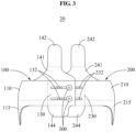
- FIG. 3 is a rear view illustrating a fixing module according to some example embodiments
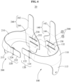
- FIG. 4 is an exploded perspective view illustrating a fixing module according to some example embodiments.
- the fixing module 20 may include the first side frame 100, the second side frame 200, and a fastening member 300.
- the first side frame 100 and the second side frame 200 may be configured to attach to opposite sides of the waist of the user.
- the first side frame 100 and the second side frame 200 may be connected to each other to form a single closed curve, for example, around the waist of the user.
- the first side frame 100 and the second side frame 200 may be detachable from each other. Therefore, the first side frame 100 and the second side frame 200 may also be referred to as a "first separable frame” and a “second separable frame”, respectively.
- the first side frame 100 may cover one side surface of the waist of the user, a portion of a front surface of the waist of the user, and a portion of a rear portion of the waist of the user.
- the first side frame 100 may fit around half of the pelvis of the user.
- the first side frame 100 may be provided roughly in a U-shape.
- the first side frame 100 may be provided using a relatively thin board.
- the first side frame 100 may be provided using a flexible material to improve a degree of contact with the user. In this example, the first side frame 100 may be deformed based on a shape of the user to be in close contact with the user.
- the first side frame 100 includes a first central portion 110, a first front extending portion 120, and a first rear extending portion 130.
- the first central portion 110 may include a curved surface corresponding to one side surface of the user, and be disposed on the one side surface of the user.
- the first central portion 110 includes a joint mounting portion 115 configured to extend toward a hip joint portion of the user.
- the joint mounding portion 115 may be provided to cover the hip joint portion.
- the rotating member 42 of FIG. 1 may be provided on the joint mounting portion 115.
- the first front extending portion 120 may extend from the first central portion 110 to cover at least a portion of the front surface of the user.
- the first front extending portion 120 may be provided to be detachable from the second side frame 200.
- the first front extending portion 120 includes a first binding portion 122, and a first connecting portion 124.
- the first binding portion 122 may be provided to be detachable from the second side frame 200.
- the first binding portion 122 may include a base plate having a shape of a board, and a hook and loop fastener provided on the base plate.
- the first binding portion 122 may also be fastened with the second side frame 200 in a structure of a buckle.
- the shape of the first binding portion 122 is not limited thereto.
- the first and second binding portions 122, 22 may be series of buttons, tabs or posts that are adjustable, and/or form an adjustable belt like loop that is secured via pressure provided thereto.
- the fixing module 20 may include a stretchable fabric such that the fixing module 20 may be warm as clothing.
- the first connecting portion 124 may rotatably connect the first binding portion 122 to the first central portion 110.
- the first connecting portion 124 may be a ring or a hinge.
- the first rear extending portion 130 may extend from the first central portion 110 to cover at least a portion of the rear surface of the user.
- the first rear extending portion 130 may extend toward an opposite side of the first front extending portion 120 based on the first central portion 110.
- the first rear extending portion 130 may be disposed on the opposite side of the first front extending portion 120 based on the user.
- the first rear extending portion 130 may be provided to be detachable from the second side frame 200.
- the first rear extending portion 130 includes a first guide portion 132.
- the first guide portion 132 may guide the second side frame 200 to slide with respect to the first rear extending portion 130.
- the first guide portion 132 may be a slot provided lengthwise in an extending direction of the first rear extending portion 130.
- the first guide portion 132 may be referred to as a "guide slot”.
- a plurality of first guide portions 132 may be provided.
- the plurality of first guide portions 132 may be provided in parallel.
- the fastening member 300 may be connected to the first guide portion 132.
- FIG. 3 illustrates a manual adjustment of the distance between the first side frame 100 and the second side frame 200
- the distance between the first side frame 100 and the second side frame 200 may be electronically adjusted.
- the fixing module 20 may include a motor (not shown).
- the first and second side frames may be connected in a rack and pinion design such that, in response to instructions generated by a controller (not shown), the motor generates a force that causes the pinion to rotate on the rack and adjust the distance between the first side frame 100 and the second side frame 200.
- the controller may include a processor and a memory storing computer readable code, that when executed by the processor, configures the controller as a special purpose computer that is configured to control the motion assistance apparatus 10.
- the first side frame 100 may further include a first supporting member 140.
- the first supporting member 140 may include one or more of a first upper supporting member 142 and a first lower supporting member 144.
- the first supporting member 140 may stabilize the fixing member 20 when a force is applied thereto. Further, in some example embodiments, the first supporting member 140 may further include an internal pad (not shown) to further stabilize the fixing member 20 and also provide comfort to the user.
- the first upper supporting member 142 may extend from the first rear extending portion 130 in an upward direction to support a lower back of the user.
- the first side supporting member 142 may extend in a direction orthogonal to a longitudinal direction of the first rear extending portion 130.
- the first upper supporting member 142 may support a dorsal portion of the user.
- the first upper supporting member 142 may extend from the first rear extending portion 130 to a portion corresponding to about a midpoint of the dorsal portion of the user.
- the first upper supporting member 142 may include a first extension 141 whose width increases in a direction of the first rear extending portion 130 near the waist of the user.
- the first lower supporting member 144 may extend from the first rear extending portion 130 in a downward direction to support a lower side of the user.
- the first lower supporting member 144 may extend in a direction orthogonal to the longitudinal direction of the first rear extending portion 130.
- the first lower supporting member 144 may support a hip portion of the user.
- the first side frame 100 may include a reinforcing material (not shown), for example a pad, on an interior surface thereof.
- the reinforcing material may stabilize the fixing member 20 and also provide comfort to the user.
- the second side frame 200 may be provided in a shape symmetrical to the first side frame 100.
- the same names may be used to describe the elements included in the first side frame 100 described above and elements having common functions. Unless otherwise mentioned, the descriptions on the first side frame 100 may be applicable to the second side frames 200.
- the second side frame 200 may cover a remaining portion of the waist of the user yet to be covered by the first side frame 100.
- the second side frame 200 may covering another side of the waist of the user, a remaining portion of the front surface of the waist user, and a remaining portion of the rear portion of the waist of the user. At least a portion of the second side frame 200 may overlap the first side frame 100.
- the second side frame 200 may include a second central portion 210, a second front extending portion 220, and a second rear extending portion 230.
- the second central portion 210 may include a curved surface corresponding to one of the side surfaces of the waist of the user, and configured to attach to this side surface of the waist of the user.
- the second central portion 210 may be disposed to face the first central portion 110.
- the second central portion 210 may include a joint mounting portion 215 configured to extend toward a hip joint portion of the user.
- the joint mounting portion 215 may be provided to cover the hip joint portion.
- the second front extending portion 220 may extend from the second central portion 210 to cover at least a portion of the front surface of the waist of the user.
- the second front extending portion 220 may be provided to be detachable from the first binding portion 122.
- the second front extending portion 220 includes a second binding portion 222, and a second connecting portion 224.
- the second rear extending portion 230 may extend from the second central portion 210 to cover at least a portion of the rear surface of the user.
- the second rear extending portion 230 may extend towards an opposite side of the second front extending portion 220 based on the second central portion 210.
- the second rear extending portion 230 may be disposed on the opposite sides of the second front extending portion 220 based on the user.
- the second rear extending portion 230 may be provided to be detachable from the first rear extending portion 130.
- the second rear extending portion 230 may include a second guide portion 232.
- the second guide portion 232 may guide the first rear extending portion 130 to slide with respect to the second rear extending portion 230.
- the second guide portion 232 may be a slot provided lengthwise in an extending direction of the second rear extending portion 230.
- the second guide portion 232 may be provided in a shape corresponding to the first guide portion 132.
- the second guide portion 232 may overlap at least a portion of the first guide portion 132.
- the fastening member 300 may be connected to the overlapping portion between the second guide portion 232 and the first guide portion 132.
- the fastening member 300 may fasten the second rear extending portion 230 with the first rear extending portion 130.
- the second side frame 200 may further include a second supporting member 240.
- the second supporting member 240 may stabilize the fixing member 20 when a force is applied thereto. Further, in some example embodiments, the second supporting member 240 may further include an internal pad (not shown) to further stabilize the fixing member 20 and also provide comfort to the user.
- the second supporting member 240 includes a second upper supporting member 242, and a second lower supporting member 244. While FIG. 4 illustrates that both the first side frame 100 and the second side frame 200 each include a supporting member 140, 240, in other example embodiments, only one of the first side frame 100 and the second side frame 200 may include a supporting member. For example, a single supporting member may be attached to one of the side frames in relatively closer contact to the user when the two side frames 100, 200 overlap around the user.
- the second upper supporting member 242 may be provided in a shape symmetrical to the first upper supporting member 142.
- the second upper supporting member 242 may include a second extension 241.
- the second upper supporting member 242 and the first upper supporting member 142 may be disposed on both sides based on a spine of the user, respectively, to support erector spinae muscles of the user.
- the second lower supporting member 244 may be provided in a shape symmetrical to the first lower supporting member 144.
- the second lower supporting member 244 and the first lower supporting member 144 may be disposed to support hip muscles of the user.
- the second side frame 200 may include a reinforcing material (not shown), for example a pad, on an interior surface thereof.
- the reinforcing material may stabilize the fixing member 20 and also provide comfort to the user.
- the fastening member 300 may fasten the first side frame 100 with the second side frame 200.
- the fastening member 300 may penetrate through the first guide portion 132 and the second guide portion 232, and prevent relative movements of the first rear extending portion 130 and the second rear extending portion 230.
- the fastening member 300 may include a bolt and a nut configured to pressurize the first rear extending portion 130 and the second rear extending portion 230 simultaneously.
- one of the first guide portion 132 or the second guide portion 232 may be provided in a form of a threaded hole, and the fastening member 300 may be a bolt having threads corresponding to the hole.
- FIG. 5 is an exploded perspective view illustrating a fixing module according to some example embodiments.
- the fixing module 20 may include the first side frame 100, the second side frame 200, the fastening member 300, and a supporting member 400.
- the supporting member 400 may include a fixing portion 410, an upper supporting member 420, and a lower supporting member 430.
- the fixing portion 410 may overlap the first side frame 100 and the second side frame 200.
- the first rear extending portion 130 may be fixed to one side of the fixing portion 410, and the second rear extending portion 230 may be fixed to another side of the fixing portion 410.
- a third guide portion 412 may be provided in the fixing portion 410.
- the third guide portion 412 may be provided in a shape corresponding to the first guide portion 132 and the second guide portion 232.
- the upper supporting member 420 may extend from the fixing portion 410 in an upward direction to support an upper side of the user.
- the upper supporting member 420 may extend in a direction orthogonal to a longitudinal direction of the fixing portion 410.
- the upper supporting member 420 may support a dorsal portion of the user.
- the upper supporting member 420 may extend from the fixing portion 410 to a portion corresponding to a midpoint of the dorsal portion of the user.
- the lower supporting member 430 may extend from the fixing portion 410 in a downward direction to support a lower side of the user.
- the lower supporting member 430 may extend in a direction orthogonal to the longitudinal direction of the fixing portion 410.
- the lower supporting member 430 may support a hip portion of the user.
- the fastening member 300 may include a first fastening member configured to fasten the first rear extending portion 130 with the fixing portion 410, and a second fastening member configured to fasten the second rear extending portion 230 with the fixing portion 410. While FIG. 5 illustrates two fastening members, the number of fastening members may vary. For example, in other example embodiments a single fastening member may be used to fasten the first rear extending portion 130 and the second rear extending portion 230 with the fixing portion 410.
- FIG. 6 is a perspective view illustrating a supporting member according to some example embodiments.
- a supporting member 500 may be applicable to at least one of the supporting members described above to provide increased flexibility in a central portion and increased stiffness in an end portion thereof.
- the supporting member 500 may include a fixing portion 510 in which a guide portion 512 is provided, an upper supporting member 520, a lower supporting member 530, and a stiffening device 550.
- the upper supporting member 520 includes an upper plate 521 provided in a shape of a board extending from the fixing portion 510 in an upward direction, and a plurality of upper protruding portions 522 configured to protrude from the upper plate 521 such that the upper plate 521 is ribbed.
- the plurality of upper protruding portions 522 may be disposed to be spaced apart from each other in a longitudinal direction of the upper plate 521.
- the plurality of upper protruding portions 522 may be disposed in parallel.
- the lower supporting member 530 may include a lower plate 531 provided in a shape of a board extending from the fixing portion 510 in a downward direction, and a plurality of lower protruding portions 532 configured to protrude from the lower plate 531 such that the lower plate 531 is ribbed.
- the plurality of lower protruding portions 532 may be disposed to be spaced apart from each other in a longitudinal direction of the lower plate 531.
- the plurality of lower protruding portions 532 may be disposed in parallel.
- the stiffening device 550 may reinforce a stiffness of the upper supporting member 520 or the lower supporting member 530.
- the stiffener 550 may increase a stiffness of both end portions of the upper supporting member 520 or the lower supporting member 530 to be greater than a stiffness of the central area of the upper supporting member 520 or the lower supporting member 530.
- the stiffener 550 may be disposed to penetrate through the plurality of upper protruding portions 522 and the plurality of lower protruding portions 532.
- the stiffening device 550 may be embedded in width directions of the upper plate 521 and the lower plate 531, and extend in longitudinal directions of the upper plate 521 and the lower plate 531.
- the stiffening device 550 may be a linear material such as, for example, a wire.
- the ends of the stiffening device 550 may be fixed to the ends of the upper plate 521 and/or the lower plate 531, and a center portion of the stiffening device 550 may be unfixed from a central portion of the upper plate 521 and/or the lower plate 531.
- FIG. 7 is a perspective view illustrating a supporting member according to example embodiments.
- a supporting member 620 may be applicable to at least one of the upper supporting member and the lower supporting member described above to provide increased flexibility in a central portion and increased stiffness in the end portions thereof.
- the supporting member 620 may include a first frame 630, a second frame 640, a connecting end portion 650, and an applying end portion 660.
- the first frame 630 may include a first plate 632, a first protruding portion 634, and a first hanging portion 636.
- the first plate 632 may be formed using a thin elastic board, for example, a material such as plastic, and steel.
- the first protruding portion 634 may protrude from the first plate 632 toward the second frame 640.
- a plurality of first protruding portions 634 may be disposed to be spaced apart from each other in a longitudinal direction of the first plate 632.
- the first protruding portion 634 may be provided lengthwise in a direction orthogonal to the longitudinal direction of the first plate 632.
- a cross-section area of the first protruding portion 634 may decrease as a distance from the first plate 632 increases.
- a width of an upper side of the first protruding portion 634 may be smaller than a width of a lower side of the first protruding portion 634.
- the first protruding portion 634 may have an inclined surface in a shape of a taper.
- the second protruding portion 644 may move along inclined surface without being obstructed by the first protruding portions 634.
- the first hanging portion 636 may prevent a separation of the second frame 640 from the first frame 630.
- the first hanging portion 636 may be provided in a form of a groove including side surfaces of the first protruding portion 634 and an inner surface of the first plate 632. As shown in FIG. 7 , the first hanging portion 636 may be provided in a form of a trapezoidal groove. To have a form of such a groove, a side surface of the first protruding portion 634 may protrude toward an inner side as a distance from the first plate 632 increases.
- first protruding portions 634 when first protruding portions 634 are arranged in two rows along both edges of the first plate 632, side surfaces of the first protruding portions 634 may be provided to protrude toward a center as a distance from the first plate 632 increases. These side surfaces of the first protruding portions 634 and the inner surface of the first plate 632 may be combined with a second hanging portion 646 of the second frame 640 to form a groove that prevents a separation.
- the second frame 640 may be provided in a shape corresponding to the first frame 630.
- the second frame 640 includes a second plate 642, the second protruding portion 644, and the second hanging portion 646.
- the second plate 642 may be provided in a shape corresponding to the first plate 632, and disposed to be spaced apart from the first plate 632.
- the second plate 642 may be formed using a thin elastic board, for example, a material such as plastic, and steel.
- a space between the second plate 642 and the first plate 632 may increases from the applying end portion 660 toward the connecting end portion 650.
- a distance between the second plate 642 and the first plate 632 may increase as a distance from the applying end portion 660 increases.
- the second protruding portion 644 may protrude from the second plate 642 toward the first plate 632.
- a plurality of second protruding portions 644 may be disposed to be spaced apart from each other in a longitudinal direction of the second plate 642.
- the second protruding portion 644 may be provided lengthwise in a direction orthogonal to the longitudinal direction of the second plate 642.
- the second hanging portion 646 may prevent a separation of the first frame 630 from the second frame 640. As shown in FIG. 7 , a cross-section of the second hanging portion 646 may be provided in a shape of a reversed trapezoidal dove tail.
- the second hanging portion 646, of which a width increases from the second plate 642 toward the first plate 632, may be combined with the first hanging portion 636 provided in a trapezoidal shape to prevent a separation of the second plate 642.
- the connecting end portion 650 may be connected to the first rear extending portion 130 or the second rear extending portion 230 of FIGS. 1 through 4 , or the fixing portion 410 of FIG. 5 .
- the applying end portion 660 may apply force to a user to offset a torsional moment when the torsional moment is applied to the fixing module 20 due to a reaction resulting from rotation of the joint assembly 40.
- the applying end portion 660 may apply force to an upper side or a lower side of the user, for example, a back or hips.
- a thickness of the applying end portion 660 may be set to be greater than a sum of a thickness of the first frame 630 adjacent to the applying end portion 660 and a thickness of the second frame 640 adjacent to the applying end portion 660.
- end portions of a power transmitting frame for example, the first side frame 100, to which both end portions of the first frame 630 and the second frame 640 are fixed, respectively, may have a relatively great stiffness resistant to a torsion.
- a central portion of the first frame 630 may relatively move with respect to a central portion of the second frame 640.
- a central portion of the power transmitting frame for example, the first side frame 100 may have a greater flexibility than an end portion thereof.
- a stiffness of both end portions of the power transmitting frame for example, the first side frame 100 may be greater than a stiffness of a central portion thereof.
- the power transmitting frame for example, the first side frame 100 may prevent buckling of the first frame 630 or the second frame 640 while maintaining a flexibility of the central portion of the first frame 630 or the second frame 640.
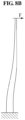
- FIGS. 8A through 8C illustrate a supporting member deformed when an external force is applied to the supporting member according to example embodiments.
- FIG. 8A illustrates a state in which a load is not applied to the supporting member
- FIG. 8B illustrates a state in which a load F is applied to an end portion of the supporting member
- FIG. 8C illustrates a state in which a load F is applied to a central portion of the supporting module.
- a stiffness of an end portion of the supporting member may be greater than a stiffness of the central portion thereof.
- the end portion of the supporting member may resist the load F and thus may not experience little deformation.
- FIG. 8C when the identical load F is applied to the central portion of the supporting member, due to the flexibility of the central portion of the supporting member, the central portion may experience greater deformation.
- a conventional longitudinal member made of a flexible material may be weaker as a distance from a fixing end increases. Thus, force may not be transmitted properly at an end portion of the longitudinal member including the flexible material.
- a conventional longitudinal member may instead be made from a stiff material to transmit force properly at an end portion thereof.
- a flexibility of the longitudinal member including the stiff material may decrease at a central portion thereof.
- the longitudinal member including the stiff material may have difficulty in handling changes in a volume of a user with respect to various motion states. In this example, a frictional force with the user may increase.
- a supporting member may include a flexible central portion and a stiff end portion and thus, the supporting member may apply sufficient supporting force corresponding to a reaction resulting from rotation of the joint assembly 40 while reducing frictional force with the user.
- the fixing module 20 may include the first side frame 100, the second side frame 200, the fastening member 300, and a supporting member 700 that is adjustable.
- the supporting member 700 may include a fixing portion 710, an upper supporting member 720, and a lower supporting member 730.
- the fixing portion 710 may overlap the first side frame 100 and the second side frame 200.
- the first rear extending portion 130 may be fixed to one side of the fixing portion 710, and the second rear extending portion 230 may be fixed to another side of the fixing portion 710.
- a third guide portion 712 may be provided in the fixing portion 710.
- the third guide portion 712 may include one or more slots provided in a direction perpendicular to the first guide portion 132 of the first side frame 100 and the second guide portion 232 of the second side frame 200.
- the third guide portion 712 may include two parallel slots that extend in a direction perpendicular to the first and second guide portions 132, 232.
- a position of the supporting member 700 may be adjusted in a vertical direction with respect to the first side frame 100 or the second side frame 200.
- the fastening member 300 may include a first fastening member configured to fasten the first rear extending portion 130 with the fixing portion 710, and a second fastening member configured to fasten the second rear extending portion 230 with the fixing portion 710. While FIG. 9 illustrates two fastening members, the number of fastening members may vary. For example, in other example embodiments a single fastening member may be used to fasten the first rear extending portion 130 and the second rear extending portion 230 with the fixing portion 710.
Landscapes
- Health & Medical Sciences (AREA)
- Engineering & Computer Science (AREA)
- Life Sciences & Earth Sciences (AREA)
- Veterinary Medicine (AREA)
- Public Health (AREA)
- General Health & Medical Sciences (AREA)
- Animal Behavior & Ethology (AREA)
- Heart & Thoracic Surgery (AREA)
- Vascular Medicine (AREA)
- Biomedical Technology (AREA)
- Orthopedic Medicine & Surgery (AREA)
- Nursing (AREA)
- Epidemiology (AREA)
- Pain & Pain Management (AREA)
- Physical Education & Sports Medicine (AREA)
- Rehabilitation Therapy (AREA)
- Mechanical Engineering (AREA)
- Robotics (AREA)
- Rehabilitation Tools (AREA)
- Manipulator (AREA)
- Automatic Cycles, And Cycles In General (AREA)
- Prostheses (AREA)
Claims (14)
- Befestigungsvorrichtung (20) für eine Bewegungsunterstützungsvorrichtung, umfassend:einen ersten seitlichen Rahmen (100), der Folgendes enthält:einen ersten zentralen Abschnitt (110), der konfiguriert ist, um an einer Seite eines Benutzers angebracht zu werden;einen ersten sich nach vorne erstreckenden Abschnitt (120), der so konfiguriert ist, dass er sich von dem ersten zentralen Abschnitt (110) entlang einer Vorderseite des Benutzers erstreckt; undeinen ersten sich nach hinten erstreckenden Abschnitt (130), der so konfiguriert ist, dass er sich von dem ersten zentralen Abschnitt (110) entlang einer Rückseite des Benutzers erstreckt; undeinen zweiten seitlichen Rahmen (200), der Folgendes enthält:einen zweiten zentralen Abschnitt (210), der konfiguriert ist, um an einer anderen Seite des Benutzers angebracht zu werden, so dass der zweite zentrale Abschnitt (210) dem ersten zentralen Abschnitt (110) gegenüberliegt und von dem ersten zentralen Abschnitt (110) um einen Abstand getrennt ist, wobei ein Abschnitt des Benutzers dazwischen eingefasst ist, wobei der Abstand zwischen dem ersten zentralen Abschnitt (110) und dem zweiten zentralen Abschnitt (210) einstellbar ist;einen zweiten sich nach vorne erstreckenden Abschnitt (220), der so konfiguriert ist, dass er sich von dem zweiten zentralen Abschnitt (210) entlang der Vorderseite des Benutzers erstreckt; undeinen zweiten sich nach hinten erstreckenden Abschnitt (230), der so konfiguriert ist, dass er sich von dem zweiten zentralen Abschnitt (210) entlang der Rückseite des Benutzers erstreckt,wobei der erste sich nach vorne erstreckende Abschnitt (120) und der zweite sich nach vorne erstreckende Abschnitt (220) voneinander lösbar sind und so konfiguriert sind, dass sie sich um eine Vorderseite des Benutzers in einem einstellbaren vorderen Überlappungsbereich überlappen,wobei mindestens ein seitlicher Rahmen unter dem ersten seitlichen Rahmen (100) und dem zweiten seitlichen Rahmen (200) ferner Folgendes umfasst:ein Stützelement (140, 240, 500, 620, 700), das so konfiguriert ist, dass es sich von einem sich nach hinten erstreckenden Abschnitt des mindestens einen seitlichen Rahmens in einer kranialen und/oder einer kaudalen Richtung erstreckt;dadurch gekennzeichnet, dass der erste sich nach hinten erstreckende Abschnitt (130) und der zweite sich nach hinten erstreckende Abschnitt (230) voneinander lösbar sindund so konfiguriert sind, dass sie sich um eine Rückseite des Benutzers in einem einstellbaren hinteren Überlappungsbereich überlappen, wobei der erste sich nach hinten erstreckende Abschnitt (130) so konfiguriert ist, dass er in Bezug auf den zweiten sich nach hinten erstreckende Abschnitt (230) gleitet.
- Befestigungsvorrichtung (20) nach Anspruch 1, wobei der erste sich nach vorne erstreckende Abschnitt (120) Folgendes umfasst:einen Bindungsabschnitt (122), der konfiguriert ist, um sich an den zweiten sich nach vorne erstreckenden Abschnitt zu binden; undeinen Verbindungsabschnitt (124), der konfiguriert ist, um den Bindungsabschnitt drehbar mit dem ersten zentralen Abschnitt zu verbinden.
- Befestigungsvorrichtung (20) nach einem der vorhergehenden Ansprüche, wobei der erste sich nach hinten erstreckende Abschnitt (130) ein dort hindurch verlaufendes erstes Führungsloch enthält und der zweite sich nach hinten erstreckende Abschnitt (230) ein zweites Führungsloch enthält, das dem ersten Führungsloch entspricht, und
wobei die Befestigungsvorrichtung ein Befestigungselement (300) umfasst, das so konfiguriert ist, dass es durch das erste Führungsloch und das zweite Führungsloch geht, um Relativbewegungen des ersten sich nach hinten erstreckenden Abschnitts (130) und des zweiten sich nach hinten erstreckenden Abschnitts (230) zu verhindern. - Befestigungsvorrichtung (20) nach einem der vorhergehenden Ansprüche, wobei der erste seitliche Rahmen (100) ein erstes oberes Stützelement (142) enthält, das so konfiguriert ist, dass es sich von dem ersten sich nach hinten erstreckenden Abschnitt (130) in einer kranialen Richtung erstreckt,der zweite seitliche Rahmen (200) ein zweites oberes Stützelement (242) enthält, das so konfiguriert ist, dass es sich von dem zweiten sich nach hinten erstreckenden Abschnitt (230) in eine kraniale Richtung erstreckt, unddas erste obere Stützelement (142) und das zweite obere Stützelement (242) so konfiguriert sind, dass sie sich zu beiden Seiten der Wirbelsäule des Benutzers erstrecken, um die Rückenstreckmuskeln des Benutzers zu stützen.
- Befestigungsvorrichtung (20) nach einem der vorhergehenden Ansprüche, wobei der erste seitliche Rahmen (100) ein erstes unteres Stützelement (144) enthält, das so konfiguriert ist, dass es sich von dem ersten sich nach hinten erstreckenden Abschnitt (130) in einer kaudalen Richtung erstreckt, um die Muskeln in einer ersten Hüfte des Benutzers zu stützen,
der zweite seitliche Rahmen (200) ein zweites unteres Stützelement (144) enthält, das so konfiguriert ist, dass es sich von dem zweiten sich nach hinten erstreckenden Abschnitt (230) in eine kaudale Richtung erstreckt, um die Muskeln in einer zweiten Hüfte des Benutzers zu stützen. - Befestigungsvorrichtung (20) nach einem der vorhergehenden Ansprüche, wobei das Stützelement (500, 620, 700) Folgendes umfasst:eine Platte (521, 531, 632, 642), die orthogonal zu einer Längsrichtung des sich nach hinten erstreckenden Abschnitts ist; undeine Vielzahl von vorstehenden Abschnitten (522, 532, 634, 644), die konfiguriert sind, um von der Platte vorzustehen.
- Befestigungsvorrichtung (20) nach Anspruch 6, wobei die Vielzahl von vorstehenden Abschnitten (522, 532) in einer Längsrichtung der Platte (521, 531) voneinander beabstandet sind, wobei das Stützelement vorzugsweise Folgendes umfasst:
eine Versteifungsvorrichtung (550), die so konfiguriert ist, dass sie durch die Vielzahl von vorstehenden Abschnitten (522, 532) geht, um die Enden des Stützelements (500) zu versteifen. - Befestigungsvorrichtung (20) nach einem der vorhergehenden Ansprüche, wobei das Stützelement (500, 620, 700) Folgendes umfasst:eine Platte (521, 531, 634, 644), die orthogonal zu einer Längsrichtung des sich nach hinten erstreckenden Abschnitts ist, wobei die Platte Endabschnitte und einen zentralen Abschnitt aufweist;eine Versteifungsvorrichtung (550), die konfiguriert ist, um an der Platte angebracht zu werden, so dass die Versteifungsvorrichtung an den Endabschnitten der Platte befestigt ist und nicht an dem zentralen Abschnitt befestigt ist;
und/oderwobei das Stützelement (500, 620) Folgendes umfasst:eine Platte (521, 532, 634, 644), die orthogonal zu einer Längsrichtung des sich nach hinten erstreckenden Abschnitts ist; undeinen Versteifungsdraht (550), der konfiguriert ist, um an einem Endabschnitt der Platte in einer Breitenrichtung der Platte eingebettet zu werden und sich in einer Längsrichtung der Platte zu erstrecken;und/oder wobei das Stützelement (500, 620) konfiguriert ist, um eine Länge aufzuweisen, die größer als seine Breite ist, undeine Steifigkeit der beiden Endabschnitte des Stützelements größer ist als eine Steifigkeit eines zentralen Bereichs des Stützelements in einer Längsrichtung des Stützelements. - Bewegungsunterstützungsvorrichtung (10), die Folgendes umfasst:die Befestigungsvorrichtung (20) nach einem der vorhergehenden Ansprüche, wobei die Befestigungsvorrichtung einen ersten trennbaren Rahmen (100) enthält, der konfiguriert ist, um an einer ersten seitlichen Oberfläche eines Benutzers montiert zu werden, und einen zweiten trennbaren Rahmen (200), der konfiguriert ist, um an einer zweiten seitlichen Oberfläche des Benutzers montiert zu werden, wobei ein Abstand zwischen dem ersten trennbaren Rahmen und dem zweiten trennbaren Rahmen einstellbar ist;ein Antriebsmodul (30), das an der Befestigungsvorrichtung (20) angebracht ist; undeine Gelenkanordnung (40), die konfiguriert ist, um sich unter Verwendung von aus dem Antriebsmodul empfangener Leistung zu drehen, um eine Drehbewegung von zumindest einem Gelenk des Benutzers zu unterstützen.
- Bewegungsunterstützungsvorrichtung (10) nach Anspruch 9, wobei der erste trennbare Rahmen (100) und der zweite trennbare Rahmen (200) ein flexibles Material enthalten, und die Befestigungsvorrichtung ferner Folgendes umfasst.
ein oberes Stützelement (142) und ein unteres Stützelement (144), die so konfiguriert sind, dass sie sich in Richtung einer Oberseite bzw. einer Unterseite des Benutzers erstrecken, wobei das obere Stützelement (142) so konfiguriert ist, dass es Druck auf die Oberseite des Benutzers ausübt, wenn sich die Gelenkanordnung (40) in eine erste Richtung dreht, und das untere Stützelement (144) so konfiguriert ist, dass es Druck auf die Unterseite des Benutzers ausübt, wenn sich die Gelenkanordnung (40) in eine zweite Richtung dreht, die sich von der ersten Richtung unterscheidet. - Bewegungsunterstützungsvorrichtung (10) nach Anspruch 9 oder 10, wobei die Bewegungsunterstützungsvorrichtung (10) ferner Folgendes umfasst:eine Befestigungsvorrichtung (20), die so konfiguriert ist, dass sie an der Taille eines Trägers derselben angebracht werden kann, wobei die Befestigungsvorrichtung (20) eine Vielzahl von ineinandergreifenden Rahmen (100, 200) enthält, die um einen Abstand getrennt sind, wobei die Befestigungsvorrichtung so konfiguriert ist, dass der Abstand zwischen den ineinandergreifenden Rahmen eingestellt werden kann, um die Bewegungsunterstützungsvorrichtung an der Taille des Trägers zu sichern;eine Vielzahl von Anbringungsvorrichtungen, die so konfiguriert sind, dass sie an den Oberschenkeln des Trägers angebracht werden können; undeine Vielzahl von Gelenkanordnungen, die an jeweiligen aus der Vielzahl von seitlichen Rahmen angebracht sind, wobei die Gelenkanordnungen so konfiguriert sind, dass sie ein Drehmoment auf die Vielzahl von Anbringungsvorrichtungen ausüben, um den Benutzer bei der Bewegung seiner Hüftgelenke zu unterstützen.
- Bewegungsunterstützungsvorrichtung nach Anspruch 11, wobei die Vielzahl von ineinandergreifenden Rahmen einen ersten ineinandergreifenden Rahmen (100) und einen zweiten ineinandergreifenden Rahmen (200) enthält, wobei der erste ineinander greifende Rahmen (100) konfiguriert ist, um sich von dem zweiten ineinandergreifenden Rahmen (200) zu lösen, um es dem Benutzer zu erlauben, die Befestigungsvorrichtung zu entfernen und/oder wobei die Vielzahl von ineinander greifenden Rahmen hintere Abschnitte (130, 230) enthält, die konfiguriert sind, um eine jeweilige Seite des unteren Rückens des Trägers zu berühren, und vordere Abschnitte (120, 220), die konfiguriert sind, um eine jeweilige Seite eines unteren Bauches des Trägers zu berühren, und
ein erster der hinteren Abschnitte (130, 230) und der vorderen Abschnitte (120, 220) der Vielzahl von ineinandergreifenden Rahmen (100, 200) konfiguriert ist, um zuzulassen, dass ein Befestigungselement (300) durch einen darin befindlichen Führungsschlitz geht, um zuzulassen, dass ein erster der Vielzahl von ineinandergreifenden Rahmen (100, 200) relativ zu einem zweiten der Vielzahl von ineinandergreifenden Rahmen (200, 100) gleitet; und ein zweiter der hinteren Abschnitte (230, 130) und der vorderen Abschnitte (220, 120) der Vielzahl von ineinandergreifenden Rahmen (100, 200) eine Klammer enthält, die konfiguriert ist, um den ersten ineinandergreifenden Rahmen (100) wahlweise an dem zweiten ineinandergreifenden Rahmen (200) zu befestigen. - Bewegungsunterstützungsvorrichtung nach Anspruch 11 oder 12, wobei die Befestigungsvorrichtung ein Stützelement (500, 620, 700) enthält, das so konfiguriert ist, dass es sich in einer kranialen und/oder kaudalen Richtung von der Befestigungsvorrichtung (20) erstreckt, wobei das Stützelement (500, 620, 700) so konfiguriert ist, dass es eine Torsionskraft ausgleicht, die erzeugt wird, wenn die Vielzahl von Gelenkanordnungen (50) das Drehmoment auf die Anbringungsvorrichtungen ausübt.
- Bewegungsunterstützungsvorrichtung nach Anspruch 13, wobei das Stützelement (500, 620, 700) eine solche Form aufweist, dass eine Steifigkeit des Stützelements in Richtung der distalen Enden davon zunimmt, und/oder wobei die Befestigungsvorrichtung (20) konfiguriert ist, um den Abstand zwischen der Vielzahl von ineinandergreifenden Rahmen (100, 200) in einer ersten Richtung einzustellen und das Stützelement (500, 620, 700) in einer zweiten Richtung senkrecht zu der ersten Richtung zu bewegen, und/oder wobei die Vielzahl von ineinandergreifenden Rahmen (100, 200) in Bezug auf das Stützelement (500, 620, 700) symmetrisch sind.
Applications Claiming Priority (1)
| Application Number | Priority Date | Filing Date | Title |
|---|---|---|---|
| KR1020140107171A KR102250238B1 (ko) | 2014-08-18 | 2014-08-18 | 고정 모듈 및 이를 포함하는 운동 보조 장치 |
Publications (3)
| Publication Number | Publication Date |
|---|---|
| EP2995284A2 EP2995284A2 (de) | 2016-03-16 |
| EP2995284A3 EP2995284A3 (de) | 2016-09-07 |
| EP2995284B1 true EP2995284B1 (de) | 2025-02-26 |
Family
ID=52784878
Family Applications (1)
| Application Number | Title | Priority Date | Filing Date |
|---|---|---|---|
| EP15152670.4A Active EP2995284B1 (de) | 2014-08-18 | 2015-01-27 | Befestigungsmodul und bewegungsunterstützungsvorrichtung damit |
Country Status (5)
| Country | Link |
|---|---|
| US (1) | US10195100B2 (de) |
| EP (1) | EP2995284B1 (de) |
| JP (1) | JP6616950B2 (de) |
| KR (1) | KR102250238B1 (de) |
| CN (2) | CN110559165B (de) |
Families Citing this family (51)
| Publication number | Priority date | Publication date | Assignee | Title |
|---|---|---|---|---|
| KR102250260B1 (ko) * | 2014-07-17 | 2021-05-10 | 삼성전자주식회사 | 연결 모듈 및 이를 포함하는 운동 보조 장치 |
| CN107223044B (zh) * | 2015-02-09 | 2019-11-01 | 圣安娜高等学校 | 髋关节矫形器驱动系统 |
| US10398617B2 (en) * | 2015-04-29 | 2019-09-03 | Steering Solutions Ip Holding Corporation | Adjustable position pivot for medical assist device |
| US10588811B2 (en) | 2015-04-30 | 2020-03-17 | Steering Solutions Ip Holding Corporation | Low friction gearbox for medical assist device |
| KR102541908B1 (ko) * | 2015-07-21 | 2023-06-09 | 삼성전자주식회사 | 프레임 모듈 및 이를 포함하는 운동 보조 장치 |
| USD844794S1 (en) * | 2015-10-28 | 2019-04-02 | John R. Mitchell | Orthopaedic shoe mount |
| US10596060B2 (en) | 2015-11-26 | 2020-03-24 | Samsung Electronics Co., Ltd. | Frame assembly and motion assistance apparatus including the same |
| EP3173053B1 (de) | 2015-11-26 | 2025-04-09 | Samsung Electronics Co., Ltd. | Bewegungsunterstützungsvorrichtung mit einer rahmenanordnung |
| EP3509557B1 (de) | 2016-09-09 | 2025-08-06 | Ecole Polytechnique Fédérale de Lausanne (EPFL) | Modulares exoskelett für zum beispiel patienten mit rückenmarksverletzungen |
| FR3057484B1 (fr) * | 2016-10-14 | 2018-11-30 | Bmexo | Dispositif portable de support de charge eloignee de la personne qui la porte |
| JP6912208B2 (ja) * | 2017-01-19 | 2021-08-04 | トヨタ自動車株式会社 | 歩行補助装具 |
| KR102193845B1 (ko) * | 2017-05-25 | 2020-12-24 | 유.에스. 바이오닉스, 인크. | 외골격 장치용 조정 가능한 몸통 및 엉덩이 조립체 |
| US10835444B2 (en) * | 2017-11-13 | 2020-11-17 | Free Bionics Taiwan Inc. | Shoe assembly for a walking assist device |
| KR102586645B1 (ko) * | 2018-07-13 | 2023-10-12 | 삼성전자주식회사 | 보행 보조 장치 |
| KR102710749B1 (ko) | 2018-10-30 | 2024-09-27 | 삼성전자주식회사 | 운동 보조 장치 |
| US12364618B2 (en) * | 2019-03-13 | 2025-07-22 | Leo Ochoa | Back support system |
| KR102663601B1 (ko) * | 2019-04-04 | 2024-05-08 | 현대자동차주식회사 | 착용식 근력 보조 장치의 상완 모듈 및 이를 포함한 착용식 근력 보조 장치 |
| JP7468532B2 (ja) * | 2019-07-12 | 2024-04-16 | 東レ株式会社 | 腰部アシスト装置 |
| USD992741S1 (en) * | 2020-10-22 | 2023-07-18 | Samsung Electronics Co., Ltd. | Wearable assistance robot |
| USD992122S1 (en) * | 2020-10-22 | 2023-07-11 | Samsung Electronics Co., Ltd. | Wearable assistance robot |
| KR102934879B1 (ko) | 2020-11-20 | 2026-03-10 | 현대자동차주식회사 | 근력 보조 장치 |
| US11918475B2 (en) | 2021-03-31 | 2024-03-05 | DePuy Synthes Products, Inc. | Modular acetabular surgical implant assembly |
| CN112936232B (zh) * | 2021-04-08 | 2022-10-28 | 中国科学技术大学 | 一种辅助潜水的髋关节外骨骼机器人系统 |
| JP7738813B2 (ja) * | 2021-08-19 | 2025-09-16 | 株式会社レナーズブレイス | 医療用具 |
| USD1010140S1 (en) * | 2021-11-19 | 2024-01-02 | Samsung Electronics Co., Ltd. | Wearable robot for fitness and walking assistance |
| US12508145B2 (en) | 2022-02-01 | 2025-12-30 | Aspen Medical Products, Llc | Orthopedic brace and donning method |
| US12440365B2 (en) | 2022-02-01 | 2025-10-14 | Aspen Medical Products, Llc | Orthopedic brace having telescopic lateral panels and an adjustable pulley subsystem |
| US12521265B2 (en) * | 2022-02-01 | 2026-01-13 | Aspen Medical Products, Llc | Posterior bracing system with interchangeable extension panels |
| US20230301814A1 (en) * | 2022-02-01 | 2023-09-28 | Aspen Medical Products, Llc | Orthopedic brace having telescopic lateral panels and an interchangeable wishbone coupler |
| USD1023096S1 (en) * | 2022-05-20 | 2024-04-16 | Samsung Electronics Co., Ltd. | Wearable robot |
| USD1022222S1 (en) * | 2022-05-20 | 2024-04-09 | Samsung Electronics Co., Ltd. | Wearable robot |
| USD1022223S1 (en) * | 2022-05-20 | 2024-04-09 | Samsung Electronics Co., Ltd. | Wearable robot |
| USD1022224S1 (en) * | 2022-05-20 | 2024-04-09 | Samsung Electronics Co., Ltd. | Wearable robot |
| USD1022221S1 (en) * | 2022-05-20 | 2024-04-09 | Samsung Electronics Co., Ltd. | Wearable robot |
| USD1021990S1 (en) * | 2022-05-20 | 2024-04-09 | Samsung Electronics Co., Ltd. | Wearable robot |
| USD1059606S1 (en) | 2022-10-20 | 2025-01-28 | Samsung Electronics Co., Ltd. | Wearable robot |
| USD1057963S1 (en) | 2022-10-20 | 2025-01-14 | Samsung Electronics Co., Ltd. | Wearable robot |
| USD1058822S1 (en) | 2022-10-20 | 2025-01-21 | Samsung Electronics Co., Ltd. | Wearable robot |
| USD1057964S1 (en) * | 2022-10-20 | 2025-01-14 | Samsung Electronics Co., Ltd. | Wearable robot |
| USD1057788S1 (en) | 2022-10-20 | 2025-01-14 | Samsung Electronics Co., Ltd. | Wearable robot |
| USD1066692S1 (en) * | 2022-10-20 | 2025-03-11 | Samsung Electronics Co., Ltd. | Wearable robot |
| USD1058628S1 (en) | 2022-10-20 | 2025-01-21 | Samsung Electronics Co., Ltd. | Wearable robot |
| USD1059607S1 (en) * | 2022-10-20 | 2025-01-28 | Samsung Electronics Co., Ltd. | Wearable robot |
| USD1058629S1 (en) * | 2022-10-20 | 2025-01-21 | Samsung Electronics Co., Ltd. | Wearable robot |
| USD1066693S1 (en) * | 2022-10-20 | 2025-03-11 | Samsung Electronics Co., Ltd. | Wearable robot |
| USD1034730S1 (en) * | 2022-11-09 | 2024-07-09 | Shenzhen Enhanced Power Technology Co., Ltd. | Wearable robotic exoskeleton |
| IT202300001710A1 (it) * | 2023-02-02 | 2024-08-02 | Postura E Sport Srl | Busto correttivo ortopedico |
| US12589017B2 (en) * | 2023-10-02 | 2026-03-31 | E-Life International Co., Ltd. | Adjustable body brace and adjusting assembly thereof |
| CN118123072B (zh) * | 2024-05-06 | 2024-07-19 | 江苏春宇精密机械有限公司 | 一种加工中心生产系统及工作方法 |
| USD1104096S1 (en) * | 2024-06-18 | 2025-12-02 | Hypershell Co., Ltd. | Powered exoskeleton |
| USD1122460S1 (en) * | 2024-08-30 | 2026-04-14 | Shenzhen Kenqing Technology Co., Ltd. | Wearable robot for providing assistive force |
Citations (4)
| Publication number | Priority date | Publication date | Assignee | Title |
|---|---|---|---|---|
| US5476441A (en) * | 1993-09-30 | 1995-12-19 | Massachusetts Institute Of Technology | Controlled-brake orthosis |
| EP1792597A1 (de) * | 2004-08-27 | 2007-06-06 | HONDA MOTOR CO., Ltd. | Kontrollvorrichtung für eine gehhilfe |
| WO2012125765A2 (en) * | 2011-03-14 | 2012-09-20 | Schoen Jason A | Orthosis and methods of using the same |
| US20120316476A1 (en) * | 2011-06-10 | 2012-12-13 | Honda Motor Co., Ltd. | Walking assistance device |
Family Cites Families (39)
| Publication number | Priority date | Publication date | Assignee | Title |
|---|---|---|---|---|
| US2327207A (en) * | 1943-08-17 | Slacks and the like | ||
| FR2350120A1 (fr) | 1976-05-05 | 1977-12-02 | Hull Pierre | Jouet - tete de cheval se fixant a la taille de l'enfant au moyen d'une ceinture |
| US4523337A (en) | 1983-05-02 | 1985-06-18 | Leibowitz Martin Nick | Contoured apparel |
| US5020790A (en) | 1990-10-23 | 1991-06-04 | Board Of Supervisors Of Louisiana State University And Agricultural And Mechanical College | Powered gait orthosis |
| US5830168A (en) * | 1997-02-18 | 1998-11-03 | Orthomerica Products, Inc. | Orthopedic hip support with multi-positional joints |
| RU2182228C2 (ru) | 2000-06-16 | 2002-05-10 | Дальневосточный государственный технический университет | Способ скважинной разработки мощных подземных формаций |
| CN2508772Y (zh) * | 2001-09-12 | 2002-09-04 | 深圳市丹妮寝饰保健品有限公司 | 安眠枕 |
| JP2006505344A (ja) * | 2002-11-07 | 2006-02-16 | オスール・エイチエフ | 短下肢装具 |
| KR100481642B1 (ko) * | 2002-11-18 | 2005-04-11 | 박인식 | 경직성 뇌성마비 아동의 재활을 위한 다축 하지보조기 |
| JP4072094B2 (ja) * | 2003-05-21 | 2008-04-02 | 本田技研工業株式会社 | 歩行補助装置 |
| JP4315766B2 (ja) * | 2003-05-21 | 2009-08-19 | 本田技研工業株式会社 | 歩行補助装置 |
| JP4093912B2 (ja) | 2003-05-21 | 2008-06-04 | 本田技研工業株式会社 | 歩行補助装置 |
| KR100598504B1 (ko) | 2004-01-19 | 2006-07-13 | 재단법인 산재의료관리원 | 동력형 왕복 보행 보조기 |
| US7429253B2 (en) * | 2004-09-21 | 2008-09-30 | Honda Motor Co., Ltd. | Walking assistance system |
| KR100612031B1 (ko) | 2004-11-04 | 2006-08-11 | 학교법인 서강대학교 | 근력증강을 위한 보행보조기기 및 그 제어방법 |
| US8057410B2 (en) | 2005-04-13 | 2011-11-15 | The Regents Of The University Of California | Semi-powered lower extremity exoskeleton |
| JP4603479B2 (ja) | 2005-12-09 | 2010-12-22 | 本田技研工業株式会社 | 力伝達部材 |
| JP5229621B2 (ja) | 2007-08-20 | 2013-07-03 | 国立大学法人 筑波大学 | 装着式動作補助装置の動作補助システム及び装着式動作補助装置及び装着式動作補助装置の動作補助方法 |
| US7926879B2 (en) * | 2007-09-20 | 2011-04-19 | Herman Miller, Inc. | Load support structure |
| CN201085760Y (zh) | 2007-09-21 | 2008-07-16 | 北京瑞海博科技有限公司 | 一种截瘫步行机的可调式胸腰支撑装置 |
| JP4326580B2 (ja) | 2007-09-25 | 2009-09-09 | 本田技研工業株式会社 | 歩行補助装置の大腿部装具 |
| JP2009284919A (ja) | 2008-05-27 | 2009-12-10 | Honda Motor Co Ltd | 腰部装着具 |
| JP5161036B2 (ja) | 2008-11-06 | 2013-03-13 | 本田技研工業株式会社 | 歩行補助装置 |
| KR20100090628A (ko) * | 2009-02-06 | 2010-08-16 | 주식회사 엘지화학 | 절연된 도전성 패턴의 제조 방법 |
| JP5411003B2 (ja) | 2010-01-11 | 2014-02-12 | 本田技研工業株式会社 | 歩行補助装置 |
| KR101146112B1 (ko) | 2010-03-15 | 2012-05-16 | 한국산재의료원 | 전동보행보조기 |
| KR101142240B1 (ko) | 2010-05-12 | 2012-05-07 | 한양대학교 산학협력단 | 근력 지원용 착용형 로봇 |
| WO2012044621A1 (en) * | 2010-09-27 | 2012-04-05 | Vanderbilt University | Movement assistance device |
| CN201977985U (zh) * | 2011-01-29 | 2011-09-21 | 孙雁群 | 一种新型外固定支具 |
| US8474672B1 (en) | 2011-03-29 | 2013-07-02 | Michael R. Keith | Hiker's buddy apparatus for sharing with a hiker the carrying load of a backpack |
| JP5854719B2 (ja) * | 2011-06-10 | 2016-02-09 | 本田技研工業株式会社 | バッテリパック収容構造およびバッテリパックおよび歩行補助装置 |
| JP5690663B2 (ja) | 2011-06-15 | 2015-03-25 | 本田技研工業株式会社 | 歩行補助装置 |
| JP5714986B2 (ja) | 2011-06-10 | 2015-05-07 | 本田技研工業株式会社 | 歩行補助装置の腰部装具および歩行補助装置 |
| WO2013070253A1 (en) * | 2011-11-07 | 2013-05-16 | Haider Thomas T | Adjustable lumbar brace |
| CN102499859B (zh) | 2011-11-08 | 2014-04-16 | 上海交通大学 | 下肢外骨骼行走康复机器人 |
| ES2773853T3 (es) | 2012-06-15 | 2020-07-15 | Univ Vanderbilt | Dispositivo de asistencia al movimiento |
| US9089409B2 (en) | 2012-10-26 | 2015-07-28 | Ying-Ching Wu | Adjustable waist pad |
| US9675514B2 (en) * | 2013-03-15 | 2017-06-13 | Bionik Laboratories, Inc. | Transmission assembly for use in an exoskeleton apparatus |
| JP6357628B2 (ja) * | 2014-01-30 | 2018-07-18 | 国立大学法人 筑波大学 | 装着式動作補助装置、及び装着式動作補助装置の操作ユニット |
-
2014
- 2014-08-18 KR KR1020140107171A patent/KR102250238B1/ko active Active
- 2014-12-18 US US14/575,533 patent/US10195100B2/en active Active
-
2015
- 2015-01-27 EP EP15152670.4A patent/EP2995284B1/de active Active
- 2015-03-06 CN CN201910857589.XA patent/CN110559165B/zh active Active
- 2015-03-06 CN CN201510099047.2A patent/CN105362040B/zh active Active
- 2015-03-19 JP JP2015056769A patent/JP6616950B2/ja active Active
Patent Citations (4)
| Publication number | Priority date | Publication date | Assignee | Title |
|---|---|---|---|---|
| US5476441A (en) * | 1993-09-30 | 1995-12-19 | Massachusetts Institute Of Technology | Controlled-brake orthosis |
| EP1792597A1 (de) * | 2004-08-27 | 2007-06-06 | HONDA MOTOR CO., Ltd. | Kontrollvorrichtung für eine gehhilfe |
| WO2012125765A2 (en) * | 2011-03-14 | 2012-09-20 | Schoen Jason A | Orthosis and methods of using the same |
| US20120316476A1 (en) * | 2011-06-10 | 2012-12-13 | Honda Motor Co., Ltd. | Walking assistance device |
Also Published As
| Publication number | Publication date |
|---|---|
| US20160045387A1 (en) | 2016-02-18 |
| EP2995284A2 (de) | 2016-03-16 |
| CN110559165A (zh) | 2019-12-13 |
| JP2016041240A (ja) | 2016-03-31 |
| KR102250238B1 (ko) | 2021-05-10 |
| CN105362040A (zh) | 2016-03-02 |
| KR20160021628A (ko) | 2016-02-26 |
| JP6616950B2 (ja) | 2019-12-04 |
| CN105362040B (zh) | 2019-10-08 |
| EP2995284A3 (de) | 2016-09-07 |
| US10195100B2 (en) | 2019-02-05 |
| CN110559165B (zh) | 2022-11-22 |
Similar Documents
| Publication | Publication Date | Title |
|---|---|---|
| US10195100B2 (en) | Fixing module and motion assistance apparatus including the same | |
| US11974955B2 (en) | Frame module and motion assistance apparatus including the same | |
| EP3687743B1 (de) | Körperschnittstelle | |
| US7780616B2 (en) | Walking assistance device | |
| KR102483389B1 (ko) | 골반 고정 기구 및 이를 포함하는 운동 보조 장치 | |
| EP1637113B1 (de) | Gehhilfe | |
| JP3955304B2 (ja) | 腰部装具 | |
| CN112584811A (zh) | 用于辅助移动性的系统和装置 | |
| US10039687B2 (en) | Driving modules and motion assistance apparatuses including the same | |
| US10449666B2 (en) | Supporting modules and motion assistance apparatuses including the same | |
| WO2017026943A1 (en) | Exosuit | |
| KR20170058634A (ko) | 지지 모듈 및 이를 포함하는 운동 보조 장치 | |
| JP2023551436A (ja) | 持ち上げ補助装置と背面の装置 | |
| EP3359096B1 (de) | Stabilisierungssystem für eine knieorthese | |
| EP2965726A1 (de) | Verbessertes lumbalkorsett | |
| KR20160034174A (ko) | 힘 전달 프레임 및 이를 포함하는 운동 보조 장치 | |
| JP4112541B2 (ja) | 歩行補助装置用装着具 | |
| US10583025B2 (en) | Wearing module and motion assistance apparatus including the same |
Legal Events
| Date | Code | Title | Description |
|---|---|---|---|
| PUAI | Public reference made under article 153(3) epc to a published international application that has entered the european phase |
Free format text: ORIGINAL CODE: 0009012 |
|
| AK | Designated contracting states |
Kind code of ref document: A2 Designated state(s): AL AT BE BG CH CY CZ DE DK EE ES FI FR GB GR HR HU IE IS IT LI LT LU LV MC MK MT NL NO PL PT RO RS SE SI SK SM TR |
|
| AX | Request for extension of the european patent |
Extension state: BA ME |
|
| PUAL | Search report despatched |
Free format text: ORIGINAL CODE: 0009013 |
|
| AK | Designated contracting states |
Kind code of ref document: A3 Designated state(s): AL AT BE BG CH CY CZ DE DK EE ES FI FR GB GR HR HU IE IS IT LI LT LU LV MC MK MT NL NO PL PT RO RS SE SI SK SM TR |
|
| AX | Request for extension of the european patent |
Extension state: BA ME |
|
| RIC1 | Information provided on ipc code assigned before grant |
Ipc: A61F 5/02 20060101ALI20160801BHEP Ipc: A61F 5/01 20060101AFI20160801BHEP Ipc: B25J 9/00 20060101ALI20160801BHEP Ipc: A61H 3/00 20060101ALI20160801BHEP |
|
| STAA | Information on the status of an ep patent application or granted ep patent |
Free format text: STATUS: REQUEST FOR EXAMINATION WAS MADE |
|
| 17P | Request for examination filed |
Effective date: 20170105 |
|
| RBV | Designated contracting states (corrected) |
Designated state(s): AL AT BE BG CH CY CZ DE DK EE ES FI FR GB GR HR HU IE IS IT LI LT LU LV MC MK MT NL NO PL PT RO RS SE SI SK SM TR |
|
| STAA | Information on the status of an ep patent application or granted ep patent |
Free format text: STATUS: EXAMINATION IS IN PROGRESS |
|
| 17Q | First examination report despatched |
Effective date: 20170619 |
|
| GRAP | Despatch of communication of intention to grant a patent |
Free format text: ORIGINAL CODE: EPIDOSNIGR1 |
|
| STAA | Information on the status of an ep patent application or granted ep patent |
Free format text: STATUS: GRANT OF PATENT IS INTENDED |
|
| INTG | Intention to grant announced |
Effective date: 20240826 |
|
| GRAS | Grant fee paid |
Free format text: ORIGINAL CODE: EPIDOSNIGR3 |
|
| GRAA | (expected) grant |
Free format text: ORIGINAL CODE: 0009210 |
|
| STAA | Information on the status of an ep patent application or granted ep patent |
Free format text: STATUS: THE PATENT HAS BEEN GRANTED |
|
| AK | Designated contracting states |
Kind code of ref document: B1 Designated state(s): AL AT BE BG CH CY CZ DE DK EE ES FI FR GB GR HR HU IE IS IT LI LT LU LV MC MK MT NL NO PL PT RO RS SE SI SK SM TR |
|
| REG | Reference to a national code |
Ref country code: GB Ref legal event code: FG4D |
|
| REG | Reference to a national code |
Ref country code: CH Ref legal event code: EP |
|
| REG | Reference to a national code |
Ref country code: DE Ref legal event code: R096 Ref document number: 602015091090 Country of ref document: DE |
|
| REG | Reference to a national code |
Ref country code: IE Ref legal event code: FG4D |
|
| REG | Reference to a national code |
Ref country code: NL Ref legal event code: MP Effective date: 20250226 |
|
| PG25 | Lapsed in a contracting state [announced via postgrant information from national office to epo] |
Ref country code: RS Free format text: LAPSE BECAUSE OF FAILURE TO SUBMIT A TRANSLATION OF THE DESCRIPTION OR TO PAY THE FEE WITHIN THE PRESCRIBED TIME-LIMIT Effective date: 20250526 |
|
| PG25 | Lapsed in a contracting state [announced via postgrant information from national office to epo] |
Ref country code: FI Free format text: LAPSE BECAUSE OF FAILURE TO SUBMIT A TRANSLATION OF THE DESCRIPTION OR TO PAY THE FEE WITHIN THE PRESCRIBED TIME-LIMIT Effective date: 20250226 |
|
| PG25 | Lapsed in a contracting state [announced via postgrant information from national office to epo] |
Ref country code: PL Free format text: LAPSE BECAUSE OF FAILURE TO SUBMIT A TRANSLATION OF THE DESCRIPTION OR TO PAY THE FEE WITHIN THE PRESCRIBED TIME-LIMIT Effective date: 20250226 |
|
| PG25 | Lapsed in a contracting state [announced via postgrant information from national office to epo] |
Ref country code: ES Free format text: LAPSE BECAUSE OF FAILURE TO SUBMIT A TRANSLATION OF THE DESCRIPTION OR TO PAY THE FEE WITHIN THE PRESCRIBED TIME-LIMIT Effective date: 20250226 |
|
| REG | Reference to a national code |
Ref country code: LT Ref legal event code: MG9D |
|
| PG25 | Lapsed in a contracting state [announced via postgrant information from national office to epo] |
Ref country code: IS Free format text: LAPSE BECAUSE OF FAILURE TO SUBMIT A TRANSLATION OF THE DESCRIPTION OR TO PAY THE FEE WITHIN THE PRESCRIBED TIME-LIMIT Effective date: 20250626 Ref country code: NO Free format text: LAPSE BECAUSE OF FAILURE TO SUBMIT A TRANSLATION OF THE DESCRIPTION OR TO PAY THE FEE WITHIN THE PRESCRIBED TIME-LIMIT Effective date: 20250526 |
|
| PG25 | Lapsed in a contracting state [announced via postgrant information from national office to epo] |
Ref country code: NL Free format text: LAPSE BECAUSE OF FAILURE TO SUBMIT A TRANSLATION OF THE DESCRIPTION OR TO PAY THE FEE WITHIN THE PRESCRIBED TIME-LIMIT Effective date: 20250226 |
|
| PG25 | Lapsed in a contracting state [announced via postgrant information from national office to epo] |
Ref country code: HR Free format text: LAPSE BECAUSE OF FAILURE TO SUBMIT A TRANSLATION OF THE DESCRIPTION OR TO PAY THE FEE WITHIN THE PRESCRIBED TIME-LIMIT Effective date: 20250226 |
|
| PG25 | Lapsed in a contracting state [announced via postgrant information from national office to epo] |
Ref country code: LV Free format text: LAPSE BECAUSE OF FAILURE TO SUBMIT A TRANSLATION OF THE DESCRIPTION OR TO PAY THE FEE WITHIN THE PRESCRIBED TIME-LIMIT Effective date: 20250226 Ref country code: PT Free format text: LAPSE BECAUSE OF FAILURE TO SUBMIT A TRANSLATION OF THE DESCRIPTION OR TO PAY THE FEE WITHIN THE PRESCRIBED TIME-LIMIT Effective date: 20250626 |
|
| PG25 | Lapsed in a contracting state [announced via postgrant information from national office to epo] |
Ref country code: GR Free format text: LAPSE BECAUSE OF FAILURE TO SUBMIT A TRANSLATION OF THE DESCRIPTION OR TO PAY THE FEE WITHIN THE PRESCRIBED TIME-LIMIT Effective date: 20250527 Ref country code: BG Free format text: LAPSE BECAUSE OF FAILURE TO SUBMIT A TRANSLATION OF THE DESCRIPTION OR TO PAY THE FEE WITHIN THE PRESCRIBED TIME-LIMIT Effective date: 20250226 |
|
| REG | Reference to a national code |
Ref country code: AT Ref legal event code: MK05 Ref document number: 1769929 Country of ref document: AT Kind code of ref document: T Effective date: 20250226 |
|
| PG25 | Lapsed in a contracting state [announced via postgrant information from national office to epo] |
Ref country code: SE Free format text: LAPSE BECAUSE OF FAILURE TO SUBMIT A TRANSLATION OF THE DESCRIPTION OR TO PAY THE FEE WITHIN THE PRESCRIBED TIME-LIMIT Effective date: 20250226 |
|
| PG25 | Lapsed in a contracting state [announced via postgrant information from national office to epo] |
Ref country code: SM Free format text: LAPSE BECAUSE OF FAILURE TO SUBMIT A TRANSLATION OF THE DESCRIPTION OR TO PAY THE FEE WITHIN THE PRESCRIBED TIME-LIMIT Effective date: 20250226 |
|
| PG25 | Lapsed in a contracting state [announced via postgrant information from national office to epo] |
Ref country code: DK Free format text: LAPSE BECAUSE OF FAILURE TO SUBMIT A TRANSLATION OF THE DESCRIPTION OR TO PAY THE FEE WITHIN THE PRESCRIBED TIME-LIMIT Effective date: 20250226 |
|
| PG25 | Lapsed in a contracting state [announced via postgrant information from national office to epo] |
Ref country code: IT Free format text: LAPSE BECAUSE OF FAILURE TO SUBMIT A TRANSLATION OF THE DESCRIPTION OR TO PAY THE FEE WITHIN THE PRESCRIBED TIME-LIMIT Effective date: 20250226 |
|
| PG25 | Lapsed in a contracting state [announced via postgrant information from national office to epo] |
Ref country code: AT Free format text: LAPSE BECAUSE OF FAILURE TO SUBMIT A TRANSLATION OF THE DESCRIPTION OR TO PAY THE FEE WITHIN THE PRESCRIBED TIME-LIMIT Effective date: 20250226 |
|
| PG25 | Lapsed in a contracting state [announced via postgrant information from national office to epo] |
Ref country code: EE Free format text: LAPSE BECAUSE OF FAILURE TO SUBMIT A TRANSLATION OF THE DESCRIPTION OR TO PAY THE FEE WITHIN THE PRESCRIBED TIME-LIMIT Effective date: 20250226 Ref country code: CZ Free format text: LAPSE BECAUSE OF FAILURE TO SUBMIT A TRANSLATION OF THE DESCRIPTION OR TO PAY THE FEE WITHIN THE PRESCRIBED TIME-LIMIT Effective date: 20250226 |
|
| PG25 | Lapsed in a contracting state [announced via postgrant information from national office to epo] |
Ref country code: RO Free format text: LAPSE BECAUSE OF FAILURE TO SUBMIT A TRANSLATION OF THE DESCRIPTION OR TO PAY THE FEE WITHIN THE PRESCRIBED TIME-LIMIT Effective date: 20250226 |
|
| PG25 | Lapsed in a contracting state [announced via postgrant information from national office to epo] |
Ref country code: SK Free format text: LAPSE BECAUSE OF FAILURE TO SUBMIT A TRANSLATION OF THE DESCRIPTION OR TO PAY THE FEE WITHIN THE PRESCRIBED TIME-LIMIT Effective date: 20250226 |
|
| REG | Reference to a national code |
Ref country code: DE Ref legal event code: R097 Ref document number: 602015091090 Country of ref document: DE |
|
| PLBE | No opposition filed within time limit |
Free format text: ORIGINAL CODE: 0009261 |
|
| STAA | Information on the status of an ep patent application or granted ep patent |
Free format text: STATUS: NO OPPOSITION FILED WITHIN TIME LIMIT |
|
| PGFP | Annual fee paid to national office [announced via postgrant information from national office to epo] |
Ref country code: GB Payment date: 20251222 Year of fee payment: 12 |
|
| 26N | No opposition filed |
Effective date: 20251127 |
|
| PGFP | Annual fee paid to national office [announced via postgrant information from national office to epo] |
Ref country code: DE Payment date: 20251222 Year of fee payment: 12 |
|
| PG25 | Lapsed in a contracting state [announced via postgrant information from national office to epo] |
Ref country code: LT Free format text: LAPSE BECAUSE OF FAILURE TO SUBMIT A TRANSLATION OF THE DESCRIPTION OR TO PAY THE FEE WITHIN THE PRESCRIBED TIME-LIMIT Effective date: 20250226 |