EP2995319A1 - Système isolateur et système de contrôle de celui-ci - Google Patents
Système isolateur et système de contrôle de celui-ci Download PDFInfo
- Publication number
- EP2995319A1 EP2995319A1 EP14840527.7A EP14840527A EP2995319A1 EP 2995319 A1 EP2995319 A1 EP 2995319A1 EP 14840527 A EP14840527 A EP 14840527A EP 2995319 A1 EP2995319 A1 EP 2995319A1
- Authority
- EP
- European Patent Office
- Prior art keywords
- concentration
- unit
- work area
- air conditioning
- flag
- Prior art date
- Legal status (The legal status is an assumption and is not a legal conclusion. Google has not performed a legal analysis and makes no representation as to the accuracy of the status listed.)
- Granted
Links
Images




Classifications
-
- B—PERFORMING OPERATIONS; TRANSPORTING
- B01—PHYSICAL OR CHEMICAL PROCESSES OR APPARATUS IN GENERAL
- B01L—CHEMICAL OR PHYSICAL LABORATORY APPARATUS FOR GENERAL USE
- B01L1/00—Enclosures; Chambers
- B01L1/02—Air-pressure chambers; Air-locks therefor
- B01L1/025—Environmental chambers
-
- B—PERFORMING OPERATIONS; TRANSPORTING
- B01—PHYSICAL OR CHEMICAL PROCESSES OR APPARATUS IN GENERAL
- B01L—CHEMICAL OR PHYSICAL LABORATORY APPARATUS FOR GENERAL USE
- B01L1/00—Enclosures; Chambers
- B01L1/02—Air-pressure chambers; Air-locks therefor
-
- C—CHEMISTRY; METALLURGY
- C12—BIOCHEMISTRY; BEER; SPIRITS; WINE; VINEGAR; MICROBIOLOGY; ENZYMOLOGY; MUTATION OR GENETIC ENGINEERING
- C12M—APPARATUS FOR ENZYMOLOGY OR MICROBIOLOGY; APPARATUS FOR CULTURING MICROORGANISMS FOR PRODUCING BIOMASS, FOR GROWING CELLS OR FOR OBTAINING FERMENTATION OR METABOLIC PRODUCTS, i.e. BIOREACTORS OR FERMENTERS
- C12M37/00—Means for sterilizing, maintaining sterile conditions or avoiding chemical or biological contamination
-
- C—CHEMISTRY; METALLURGY
- C12—BIOCHEMISTRY; BEER; SPIRITS; WINE; VINEGAR; MICROBIOLOGY; ENZYMOLOGY; MUTATION OR GENETIC ENGINEERING
- C12M—APPARATUS FOR ENZYMOLOGY OR MICROBIOLOGY; APPARATUS FOR CULTURING MICROORGANISMS FOR PRODUCING BIOMASS, FOR GROWING CELLS OR FOR OBTAINING FERMENTATION OR METABOLIC PRODUCTS, i.e. BIOREACTORS OR FERMENTERS
- C12M41/00—Means for regulation, monitoring, measurement or control, e.g. flow regulation
- C12M41/12—Means for regulation, monitoring, measurement or control, e.g. flow regulation of temperature
- C12M41/14—Incubators; Climatic chambers
-
- C—CHEMISTRY; METALLURGY
- C12—BIOCHEMISTRY; BEER; SPIRITS; WINE; VINEGAR; MICROBIOLOGY; ENZYMOLOGY; MUTATION OR GENETIC ENGINEERING
- C12M—APPARATUS FOR ENZYMOLOGY OR MICROBIOLOGY; APPARATUS FOR CULTURING MICROORGANISMS FOR PRODUCING BIOMASS, FOR GROWING CELLS OR FOR OBTAINING FERMENTATION OR METABOLIC PRODUCTS, i.e. BIOREACTORS OR FERMENTERS
- C12M41/00—Means for regulation, monitoring, measurement or control, e.g. flow regulation
- C12M41/30—Means for regulation, monitoring, measurement or control, e.g. flow regulation of concentration
-
- C—CHEMISTRY; METALLURGY
- C12—BIOCHEMISTRY; BEER; SPIRITS; WINE; VINEGAR; MICROBIOLOGY; ENZYMOLOGY; MUTATION OR GENETIC ENGINEERING
- C12M—APPARATUS FOR ENZYMOLOGY OR MICROBIOLOGY; APPARATUS FOR CULTURING MICROORGANISMS FOR PRODUCING BIOMASS, FOR GROWING CELLS OR FOR OBTAINING FERMENTATION OR METABOLIC PRODUCTS, i.e. BIOREACTORS OR FERMENTERS
- C12M41/00—Means for regulation, monitoring, measurement or control, e.g. flow regulation
- C12M41/30—Means for regulation, monitoring, measurement or control, e.g. flow regulation of concentration
- C12M41/34—Means for regulation, monitoring, measurement or control, e.g. flow regulation of concentration of gas
-
- C—CHEMISTRY; METALLURGY
- C12—BIOCHEMISTRY; BEER; SPIRITS; WINE; VINEGAR; MICROBIOLOGY; ENZYMOLOGY; MUTATION OR GENETIC ENGINEERING
- C12M—APPARATUS FOR ENZYMOLOGY OR MICROBIOLOGY; APPARATUS FOR CULTURING MICROORGANISMS FOR PRODUCING BIOMASS, FOR GROWING CELLS OR FOR OBTAINING FERMENTATION OR METABOLIC PRODUCTS, i.e. BIOREACTORS OR FERMENTERS
- C12M41/00—Means for regulation, monitoring, measurement or control, e.g. flow regulation
- C12M41/48—Automatic or computerized control
-
- B—PERFORMING OPERATIONS; TRANSPORTING
- B01—PHYSICAL OR CHEMICAL PROCESSES OR APPARATUS IN GENERAL
- B01L—CHEMICAL OR PHYSICAL LABORATORY APPARATUS FOR GENERAL USE
- B01L2300/00—Additional constructional details
- B01L2300/02—Identification, exchange or storage of information
- B01L2300/023—Sending and receiving of information, e.g. using Bluetooth®
-
- B—PERFORMING OPERATIONS; TRANSPORTING
- B01—PHYSICAL OR CHEMICAL PROCESSES OR APPARATUS IN GENERAL
- B01L—CHEMICAL OR PHYSICAL LABORATORY APPARATUS FOR GENERAL USE
- B01L2300/00—Additional constructional details
- B01L2300/02—Identification, exchange or storage of information
- B01L2300/025—Displaying results or values with integrated means
- B01L2300/027—Digital display, e.g. LCD, LED
Definitions
- the present disclosure relates to an isolator system and a control system thereof that are used for experiments related to regenerative medicine and pharmaceutical production.
- Patent Literature 1 discloses an isolator configured to conduct work on tissue-derived biomaterials as target materials.
- the isolator includes: a working chamber; a reader configured to read information from a wireless tag that stores information associated with an operation target; and a work management unit configured to obtain information read with the reader, to manage work. Further, the isolator includes a monitor configured to display to a worker an operation menu for devices. Thus, work efficiency in the isolator is improved.
- the present disclosure is to provide an isolator system and a control system thereof that are capable of improving safety for workers.
- An isolator system includes : a box-shaped body case including a work area, provided in an interior of the body case, in which work is conducted in a sterile environment, and an insertion portion, provided in a front surface of the body case, into which a worker's arm is inserted; a sterilizing unit configured to supply a sterilizing substance into the work area; an air conditioning unit configured to supply and/or discharge gas with respect to the work area; a display unit with which a worker inputs a signal; a control unit configured to be coupled to the sterilizing unit, the air conditioning unit, and the display unit; and a storage unit configured to store a signal from the control unit, the control unit being configured to, after startup, confirm whether a concentration of a sterilizing substance in the work area is equal to or less than a predetermined concentration, or not, and when the concentration of the sterilizing substance in the work area exceeds the predetermined concentration, store in the storage unit a high concentration flag indicative that the concentration of the sterilizing substance in the work area is
- a control system includes: a box-shaped body case including a work area, provided in an interior of the body case, in which work is conducted in a sterile environment, and an insertion portion, provided in a front surface of the body case, into which a worker' s arm is inserted; a sterilizing unit configured to supply a sterilizing substance into the work area; an air conditioning unit configured to supply and/or discharge gas with respect to the work area; a display unit with which a worker inputs a signal; and a storage unit configured to store a signal from the control unit, the control system being configured to be coupled to the sterilizing unit, the air conditioning unit, the display unit, and the storage unit, the control system being configured to, after startup, confirm whether a concentration of a sterilizing substance in the work area is equal to or less than a predetermined concentration, or not, and when the concentration of the sterilizing substance in the work area exceeds the predetermined concentration, store in the storage unit a high concentration flag indicative that the concentration of the sterilizing substance in
- An isolator system and a control system according to the present disclosure can improve safety for workers.
- An isolator system 100 will be described hereinafter as an example of an isolator system in a first embodiment with reference to Figs. 1 to 14 .
- the isolator system 100 in the first embodiment is a device configured to perform, for example, work for cell culture, manipulation, observation, etc., in a sterile environment which has been sterilized.
- Sterilizing refers to an act of killing microorganisms, cells, etc., to bring a state closer to a sterile environment.
- the Z-axis is an axis along a vertical direction in which the isolator system 100 is provided to stand, and it is assumed that a direction toward the upper side (upward) is +Z-direction and a direction toward the lower side (downward) is -Z-direction.
- the Y-axis is an axis along a direction substantially perpendicular to the front surface and the back surface of the isolator system 100, and it is assumed that a direction extending from the front surface, where an opening for conducting work within a work area is provided, to the back surface opposite to the front surface is -Y-direction, and a direction extending from the back surface to the front surface is +Y-direction.
- the X-axis is an axis along a direction substantially perpendicular to the side surfaces on the left and right sides when seen from the front, and it is assumed that a direction extending from the left side surface to the right side surface when seen from the front is +X-direction, and a direction extending from the right side surface to the left side surface is -X-direction.
- Figs. 1 and 2 are a front view and a perspective view of the isolator system 100 according to the first embodiment, respectively.
- the isolator system 100 includes: a glove box 110; a centrifuge unit 120; an observation unit 130; a sterilizing unit 140; an air conditioning unit 150; a control unit 160; a pass box 170; an air conditioning unit 180; and diffusion fans 191, 192 ( Fig. 4 ).
- the glove box 110 includes a display 111 configured to display, at the upper front part thereof, an operation and/or a status of a device.
- the display 111 is configured to be coupled to the control unit 160 provided at the upper front part.
- a worker can input a signal with the display 111.
- the glove box 110 has a substantially box-shaped work area A, formed therein, which configures a sterile environment isolated from the surroundings.
- the glove box 110 includes a front door 112 having a plurality of openings 113 provided in the front surface.
- the glove box 110 is formed to be partitioned with airtightness so as to restrain bacterial invasion from the outside.
- ducts for discharging the gas in the work area A are formed below a work platform, on which work is conducted, and on the back side of the work area A.
- the glove box 110 according to the present embodiment is configured with stainless steel plates, which are easily cleaned and sterilized.
- the front door 112 is provided, in the front surface thereof, with the plurality of openings 113 for a worker's arms to be inserted thereinto, and gloves (not shown) are mounted to the plurality of openings 113, respectively.
- the front door 112 is openable and closable with respect to a hinge, serving as an axis, provided at an upper end portion.
- the front surface of the glove box 110 is openable and closable.
- Handles with locks 114 which are capable of locking the front door 112 as to opening/closing, are provided at the lower part of the front door 112.
- the centrifuge unit 120 is provided below the glove box 110, and can be connected from the work area A.
- the centrifuge unit 120 includes, in the interior thereof, a centrifuge configured to centrifuge a sample to be worked on within the work area A.
- the observation unit 130 is provided below the glove box 110, and can be connected from the work area A.
- the observation unit 130 includes, in the interior thereof, an observation device configured to observe a sample to be worked on within the work area A. Further, the observation unit 130 includes: an elevating mechanism capable of raising and lowering the observation device provided therewithin; and a handle, provided outside, with which the elevating mechanism is operated. A worker operates the elevating mechanism with the handle, thereby being able to lift the observation device into the work area A when the observation device is used, and accommodate the observation device in the observation unit 130 when the observation device is not used.
- Fig. 3 is a perspective view illustrating the isolator system 100 according to the first embodiment when an incubator 200 is mounted thereto.
- the incubator 200 in the isolator system 100, the incubator 200 is mounted on the side surface opposite to the side surface of the glove box 110 to which the pass box 170 is mounted.
- the incubator 200 includes a storage chamber (not shown) in the interior thereof.
- the storage chamber is a chamber in which a culture is stored, and is partitioned, as a space for restraining bacterial invasion from the outside, by a rectangular parallelepiped-shaped box body, for example.
- the storage chamber is partitioned with, for example, stainless steel plates.
- the incubator 200 is demountably configured with respect to the isolator system 100. As a result, culture can be controlled in each incubator 200.
- a dedicated incubator 200 is used for each donor, thereby being able to restrain occurrence of failures such as mix-ups of cultures.
- the sterilizing unit 140 is provided below the glove box 110 so as to supply a sterilizing substance to sterilize the work area A in the glove box 110.
- Fig. 4 is a schematic diagram illustrating a configuration of the isolator system 100 according to the first embodiment.
- the sterilizing unit 140 includes: a sterilizing liquid bottle 141; an electronic balance 148 configured to measure the weight of the sterilizing liquid bottle 141; and a water suction tube 142a and a peristaltic pump 142b for suctioning the sterilizing liquid from the sterilizing liquid bottle 141 to supply it to the nozzle 143 or the nozzle 144.
- the sterilizing unit 140 further includes: the nozzle 143 provided within the glove box 110; and the nozzle 144 provided within the pass box 170.
- the sterilizing unit 140 further includes a compressor 145a and an air supply tube 145b for supplying air to the nozzle 143 or the nozzle 144.
- the sterilizing unit 140 also includes: an air supply valve 149 for introducing the air into the water suction tube 142a.
- the air supply valve 149 is provided between the tip of the water suction tube 142a inserted into the sterilizing liquid bottle 141 and the peristaltic pump 142b.
- a switching valve 146a and a switching valve 146b are configured to be opened/closed, to control the flow of the air into the nozzle 143 or the nozzle 144.
- a switching valve 147a and a switching valve 147b are configured to be opened/closed, to control the flow of the sterilizing liquid into the nozzle 143 or the nozzle 144.
- a hydrogen peroxide solution is used as the sterilizing liquid.
- the sterilizing liquid is stored in the sterilizing liquid bottle 141, and the sterilizing liquid bottle 141 is placed on a measurement means such as the electronic balance 148.
- the electronic balance 148 is configured to measure the weight of the sterilizing liquid bottle 141 and the sterilizing liquid, and its signal is inputted to the control unit 160.
- the sterilizing liquid stored in the sterilizing liquid bottle 141 is to be supplied by a liquid delivery means, such as the peristaltic pump 142b, through the water suction tube 142a to the nozzle 143 or the nozzle 144.
- the hydrogen peroxide solution in the sterilizing liquid bottle 141 is supplied in a gradual manner by the peristaltic pump 142b to the nozzle 143 or the nozzle 144.
- the peristaltic pump 142b is provided to the water suction tube 142a, and a filter configured to remove foreign substances is provided on the downstream side with respect to the peristaltic pump 142b.
- a pressure sensor configured to detect the pressure within the water suction tube 142a is provided between the filter and the peristaltic pump 142b. With the pressure sensor, it is possible to monitor the clogging of the filter or detect abnormality such as bending of the water suction tube 142a.
- the control unit 160 can control driving of the peristaltic pump 142b and opening/closing of the air supply valve 149. Further, one end of the air supply tube 145b is mounted to the compressor 145a, and the other end thereof is mounted to the nozzle 143 or the nozzle 144. Thereby, the compressor 145a can supply air through the air supply tube 145b to the nozzle 143 or the nozzle 144.
- the air conditioning unit 150 is provided above the glove box 110 and is configured to control supply/discharge with respect to the work area A.
- the air conditioning unit 150 includes an air supply unit 150a and a discharge unit 150b.
- the air conditioning unit 150 includes an air supply inlet 151 and a discharge outlet 155 provided on an upper surface plate in the glove box 110. The air is supplied into the glove box 110 from the air supply inlet 151, and is discharged from the discharge outlet 155.
- a particulate trap filter of an HEPA filter 152 is mounted to the air supply inlet 151, and the air is supplied through the particulate trap filter into the glove box 110.
- An HEPA filter 156 is also mounted to the discharge outlet 155, and the gas within the glove box 110 is discharged through the HEPA filter 156 from the interior of the glove box 110.
- a sterilizing substance such as hydrogen peroxide is sprayed thereinto, and thereby sterilization processing of sterilizing the interior of the glove box 110 is performed.
- Fig. 5 is a block diagram illustrating a configuration of the isolator system according to the first embodiment.
- the control unit 160 is configured to be coupled to a memory 162, the display 111, the handles with locks 114, the sterilizing unit 140, the air conditioning unit 150, the air conditioning unit 180 ( Fig. 3 ) and the diffusion fans 191, 192 ( Fig. 4 ).
- the memory 162 is configured to store a signal transmitted from the control unit 160.
- the display 111 is configured to display a signal transmitted from the control unit 160.
- the handles with locks 114 are configured to lock or release the front door 112 as to opening/closing, in response to a signal transmitted from the control unit 160.
- a signal is outputted to components of the sterilizing unit 140, in response to an input from the electronic balance 148, etc.
- the sterilizing unit 140 is configured to operate the components in response to a signal transmitted from the control unit 160 to spray a sterilizing mist.
- the air conditioning unit 150 and the air conditioning unit 180 are configured to control an air supply blower 153, a discharge blower 157, and an air supply blower 183, based on a signal transmitted from the control unit 160, to supply outside air (gas) and discharge inside air.
- the diffusion fans 191, 192 are controlled based on a signal transmitted from the control unit 160.
- the control unit 160 is configured to perform a pre-operation check for checking devices and a sterilization process for sterilizing the interior of the glove box 110.
- the sterilization process includes a spray process, an exposure process, and a detoxification process.
- the spray process is a process of spraying the sterilizing mist (sterilizing substance) in the interior of the glove box 110 to sterilize it.
- the exposure process is a process of diffusing the sprayed sterilizing mist over the entire interior of the glove box 110 to sterilize it.
- the detoxification process is a process of supplying the air to the interior of the glove box 110 while discharging the gas in the glove box 110, to exchange the gas in the glove box 110, thereby reducing the concentration of the sterilizing substance in the interior of the work area A.
- the pass box 170 is provided on the side surface of the glove box 110 so that a worker puts a work item into the work area A from the outside.
- a transport space B for temporarily storing the work item is formed in the interior of the pass box 170.
- the transport space B has hermeticity against the surrounding environment.
- the work item is sterilized within the transport space B.
- an opening for moving the work item is provided, and the glove box 110 and the pass box 170 are fixed so that the opening in the side surface of the pass box 170 is opposed to an opening provided in the side surface of the glove box 110.
- the work area A and the transport space B communicate with each other with hermeticity being maintained.
- a door that is openable and closable is mounted to the opening of the pass box 170. The door can separate the transport space B and the work area A with hermeticity being maintained.
- the air conditioning unit 180 is provided above the pass box 170 and is configured to control air conditioning within the transport space B.
- the isolator system 100 includes the diffusion fans 191, 192.
- the diffusion fan 191 is provided in the glove box 110, and the diffusion fan 192 is provided in the pass box 170.
- the diffusion fan 191 is configured to diffuse the gas in the interior of the work area A, and the diffusion fan 192 is configured to diffuse the gas in the interior of the transport space.
- Fig. 6 is a diagram illustrating a main menu screen after startup of the isolator system according to the first embodiment.
- the control unit 160 when the isolator system 100 is started, the control unit 160, firstly, displays a main menu screen illustrated in Fig. 6 on the display 111. A worker selects a menu to be operated from the main menu screen, to operate the isolator system 100.
- the main menu screen displays an [END] button B1 for ending the operation of the isolator system 100, a [PRE-OPERATION CHECK] button B2 for checking the device, an [OPERATION MENU] button B3 for operating the sterilization process, etc., a [DATA SETTING] button B4 for setting various data, and an [AUTHENTICATION] button B5 for performing authentication of a worker.
- FIG. 7 is a flowchart illustrating the pre-operation check of the isolator system according to the first embodiment.
- the control unit 160 when the pre-operation check is selected, the control unit 160, firstly, confirms whether the operation normally ended when the previous operation ended (S101).
- the normal end of the operation indicates that a worker instructs termination of the operation and thereby the operation ends.
- the abnormal end of the operation indicates that electric power supply to the device is interrupted, for example, due to a power failure caused by lightning strike or the like, resulting in the device being forcibly shut down.
- the front door 112 is locked with the handles with locks 114 when power supply is OFF.
- the handles with locks 114 are in a state of being locked.
- Fig. 8 is a diagram illustrating a hydrogen-peroxide concentration confirmation screen at normal time when the pre-operation check of the isolator system 100 according to the first embodiment is performed.
- the normal hydrogen-peroxide concentration confirmation screen displays: an instruction for measuring the concentration of hydrogen peroxide to a worker; a question as to whether the concentration of hydrogen peroxide is equal to or less than the predetermined concentration or not; and a [YES] button B7 and a [NO] button B8 (concentration confirmation input part) for inputting a reply to the question.
- the screen displays also a [MAIN MENU] button B6 for returning to the main menu screen and an operating instruction space A1 for providing an instruction of an operation method to a worker, on the same screen.
- Fig. 9 is a diagram illustrating a hydrogen-peroxide concentration confirmation screen indicative that the isolator system 100 according to the first embodiment abnormally ended last time, when the pre-operation check of the isolator system is performed.
- the screen at normal time illustrated in Fig. 8 is displayed with a precaution space A2, including a precaution for a worker, being added.
- a worker measures the concentration of hydrogen peroxide remaining in the work area A, using a hydrogen peroxide gas detector tube, in response to the question illustrated in Figs. 8 , 9 , and inputs the results with the display 111.
- the control unit 160 stores, in the memory 162, a "concentration Hi flag" indicative that the concentration of hydrogen peroxide in the glove box 110 is high, and thereafter displays a device check screen illustrated in Fig. 10 on the display 111 (S104, S105, S106).
- the control unit 160 displays the device check screen illustrated in Fig. 10 on the display 111, without storing the "concentration Hi flag" in the memory 162 (S104, S106).
- the control unit 160 when the worker selects the [YES] button B7, the control unit 160 releases the locks of the handles with locks 114, to enable opening/closing of the front door 112. On the other hand, when the worker selects the [NO] button B8, the control unit 160 does not release the locks of the handles with locks 114, with the front door 112 remaining locked as to opening/closing.
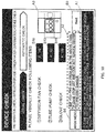
- Figs. 10 and 11 are diagrams illustrating a device check screen when a visual check in the pre-operation check of the isolator system according to the first embodiment is performed.
- the pre-operation check includes the visual check and an automatic check
- the control unit 160 displays the visual check items, which are to be visually checked by a worker in the device, on the display 111 (S106).
- confirmation buttons B10 visual check input part
- the display of each of the confirmation buttons B10 is switched from "NG” , indicative that check is not completed, to "OK", indicative that check is completed, in response to an input from the worker.
- the device check screen displays a [Next] button B9 to which completion of the check of the visual check items is inputted.
- the [Next] button B9 becomes operative when the display of the visual check item is switched to "OK".
- the [Next] button B9 becomes operative when all the plurality of the confirmation buttons B10 are switched to OK. That is, if any one of the plurality of the confirmation buttons B10 displays "NG”, the worker cannot input with the [Next] button B9, and when all the confirmation buttons B10 are switched to "OK", the worker can input with the [Next] button B9.
- the control unit 160 holds the screen display as it is.
- the control unit 160 displays an abnormality screen including the confirmation button B10 displaying "NG" indicative that the visual check items have not been completely checked or abnormality exists in the visual check items (S107, S10B).
- the control unit 160 can let the worker know that there is a possibility of abnormality in the visual check items.
- the control unit 160 displays the next device check screen, illustrated in Fig. 12 , on the display 111 (S107, S109).
- the visual check screen displays an information map A3 indicating which parts in the isolator system 100 correspond to the visual check items. This improves workability.
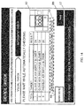
- Figs. 12 to 15 are diagrams illustrating the device check screens when the automatic check in the pre-operation check of the isolator system according to the first embodiment is performed.
- the control unit 160 performs the automatic check for checking items other than the visual check items.
- the control unit 160 displays guidance for a worker to confirm the predetermined items as preparation of the check, on the display 111.
- the control unit 160 confirms whether the predetermined items satisfy the conditions and also displays, on the same screen, whether the predetermined items satisfy the conditions.
- the control unit 160 displays the [Next] button B9, which becomes operative when the predetermined items satisfy all the conditions, similarly to the device check screen when the visual check is performed.
- the control unit 160 displays the device check screen at the time when the automatic check is being performed, illustrated in Fig. 13 , on the display 111 (S109). Further, although not illustrated in Fig. 7 , in the present embodiment, when the worker inputs with the [Next] button B9, the control unit 160 locks the front door 112 as to opening/closing using the handles with locks 114.
- the control unit 160 displays target items to be checked and the respective check results of the target items (including a display indicative of checking).
- the control unit 160 displays the [Next] button B9, which becomes operative when all the items to be checked are normal, similarly to the device check screen when the visual check is performed.
- the control unit 160 holds the screen display as it is, if any one of the check results of the items to be checked displays "NG", on the device check screen when the automatic check is performed. That is, the control unit 160 displays an abnormality screen indicative that abnormality exists in the items to be checked (S110, S111).
- the control unit 160 can let a worker to know that abnormality exists in the automatic check items.
- control unit 160 confirms whether the "concentration Hi flag" is stored in the memory 162 (S112).
- the control unit 160 transmits an operation start signal to the air conditioning unit 150, to start a detoxification process (S113).
- the detoxification process that is started herein is a process similar to the detoxification process performed in the sterilization process.
- the control unit 160 includes a counter, and measures whether a predetermined time period has passed (S114). When the predetermined time period has passed, the control unit 160 displays a screen, similar to the hydrogen-peroxide concentration confirmation screen illustrated in Fig. 8 , on the display 111 (S115). When the worker selects the [YES] button B7, the control unit 160 transmits an operation stop signal to the air conditioning unit 150, to end the detoxification process (S116).
- the control unit 160 starts measuring the predetermined time period again.
- the hydrogen-peroxide concentration confirmation screen is displayed again (S115).
- the control unit 160 repeats this operation until the [YES] button B7 is selected.
- the control unit 160 releases the locks of the handles with locks 114, to end the pre-operation check (S117).
- control unit 160 releases the locks of the handles with locks 114, to end the pre-operation check (S117).
- the isolator system 100 includes: the box-shaped glove box 110 (body case) including the work area A of a sterile environment in the interior thereof, and the opening 113 (insertion portion) for a worker's arm to be inserted in the front surface thereof; the sterilizing unit 140 (sterilizing unit) configured to supply a hydrogen peroxide (sterilizing substance), to sterilize the work area A; the air conditioning unit 150 (air conditioning unit) configured to supply and/or discharge the gas with respect to the work area A; the display 111 (display unit) with which a worker can input a signal; the control unit 160 (control unit) configured to be coupled to the sterilizing unit 140, the air conditioning unit 150, and the display 111; and the memory 162 (storage unit) configured to store a signal from the control unit 160, and the control unit 160 is configured to, after startup, confirm whether the concentration of hydrogen peroxide in the work area A is equal to or less than the predetermined concentration, or not (S104 of Fig.
- the check of the operation of the air conditioning unit 150 includes, for example, a leakage test for confirming whether airtightness is maintained in the work area A.
- the isolator system capable of improving safety for workers can be provided.
- the detoxification process can be performed by operating air conditioning unit 150 after checking the operation of the air conditioning unit 150. Therefore, such an isolator system can be provided that, even if the sterilizing substance remains in the interior at the time of startup, the device can be reliably checked, thereby being able to reduce risk of workers.
- the sterilizing substance might leak to the exterior, to expose a worker to risk. For example, damage in a glove, cracks in the front door 112 and/or a discharge pass, etc., can be considered.
- control unit 160 is configured to display a concentration confirmation screen ( Fig. 8 ) for confirming whether the concentration of hydrogen peroxide within the work area A is equal to or less than the predetermined concentration, or not, and the concentration confirmation screen is configured to display a concentration confirmation input part ([YES] button B7 and [NO] button B8) with which a worker inputs whether the concentration of hydrogen peroxide in the work area A is equal to or less than the predetermined concentration, or exceeds the predetermined concentration, and the control unit 160 is configured to, when it is inputted to the concentration confirmation input part that the concentration of hydrogen peroxide in the work area A exceeds the predetermined concentration, store the "concentration Hi flag" in the memory 162 (S104, S105).
- concentration confirmation screen Fig. 8
- concentration confirmation screen is configured to display a concentration confirmation input part ([YES] button B7 and [NO] button B8) with which a worker inputs whether the concentration of hydrogen peroxide in the work area A is equal to or less than the predetermined concentration, or exceeds the predetermined
- a worker can reliably measure the concentration of hydrogen peroxide within the work area A, and when the concentration is high, the worker can check the air conditioning unit 150 before the detoxification process. Therefore, such an isolator system capable of reducing risk of workers can be provided.
- the isolator system 100 is configured to, after startup, confirm whether abnormality existed when the previous operation ended (S101), and when abnormality existed, display warning information on the concentration confirmation screen ( Fig. 8 ), the warning information being indicative that abnormality existed when the previous operation ended (S103), and thus, when abnormality existed at the end of the previous operation, there is high possibility of high concentration of hydrogen peroxide in the work area A, and in such a case, it is possible to draw worker's attention to risk. Therefore, safety for workers can be further improved.
- control unit 160 is a control system configured to control the isolator system 100, and the control unit includes: the box-shaped glove box 110 (body case) including the work area A of a sterile environment in the interior thereof, and the opening 113 (insertion portion) for a worker' s arm to be inserted in the front surface thereof; the sterilizing unit 140 (sterilizing unit) configured to supply a hydrogen peroxide (sterilizing substance), to sterilize the work area A; the air conditioning unit 150 (air conditioning unit) configured to supply and/or discharge the gas with respect to the work area A; and the display 111 (display unit) with which a worker can input a signal, the control system being configured to be couple d to the sterilizing unit 140 , the air conditioning unit 150, the display 111, and the memory 162 (storage unit), and the control system is further configured to, after startup, confirm whether the concentration of a hydrogen peroxide in the work area is equal to or less than a predetermined concentration, or not,
- the isolator system capable of improving safety for workers can be provided.
- the detoxification process can be performed such that air conditioning unit 150 is operated after the operation of the air conditioning unit 150 is checked. Therefore, such an isolator system can be provided that, even if the sterilizing substance remains in the interior at the time of startup, the device can be reliably checked, thereby being able to reduce risk of workers.
- the sterilizing substance might leak to the exterior, to expose a worker to risk. For example, damage in a glove, cracks in the front door 112 and/or a discharge pass, etc., can be considered.
- control unit 160 is configured to display the concentration confirmation screen ( Fig. 8 ) for conf irming whether the concentration of the hydrogen peroxide in the work area A is equal to or less than the predetermined concentration, or not
- the concentration confirmation screen is configured to display the concentration confirmation input part ([YES] button B7 and [NO] button B8) with which a worker inputs whether the concentration of the hydrogen peroxide in the work area A is equal to or less than the predetermined concentration, or exceeds the predetermined concentration
- the control system is configured to, when it is inputted, to the concentration confirmation input part, that the concentration of the hydrogen peroxide in the work area A exceeds the predetermined concentration, store the "concentration Hi flag" in the memory 162. (S104, S105).
- the control system configured to control the isolator system capable of reducing risk of workers can be provided.
- the isolator system 100 is configured to, after startup, confirm whether abnormality existed when the previous operation ended (S101), and when abnormality existed, display warning information on the concentration confirmation screen ( Fig. 8 ), the warning information being indicative that abnormality existed when the previous operation ended (S103), and thus, when abnormality existed at the end of the previous operation, there is high possibility of high concentration of the hydrogen peroxide in the work area A, and in such a case, it is possible to call worker's attention to risk. Therefore, safety for workers can be further improved.
- An isolator system 101 according to a second embodiment will hereinafter be described with reference to Fig. 15 .
- the configuration of the isolator system 101 is similar to that of the isolator system 100 according to the first embodiment, the description thereof is omitted here.
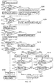
- Fig. 15 is a flow chart illustrating a pre-operation check of the isolator system 101 according to the second embodiment.
- a control unit 160 firstly displays a main menu screen as illustrated in Fig. 6 on the display 111.
- a worker selects a menu to be operated from the main menu screen, to operate the isolator system 101.
- the main menu screen displays the [END] button B1 for ending the operation of the isolator system 101, the [PRE-OPERATION CHECK] button B2 for checking devices, the [OPERATION MENU] button B3 for performing the sterilization process, etc. , the B4 for setting various data, and the B5 for performing authentication of a worker.
- the control unit 160 when the pre-operation check is selected, the control unit 160, firstly, confirms whether the operation normally ended when the previous operation ended (S201). When the operation normally ended at the end of the previous operation, the control unit 160 displays the screen illustrated in Fig. 8 on the display 111 (S202).
- control unit 160 stores "abnormality flag” in the memory 162, the "abnormality flag” being indicative that the end of the previous operation is abnormal, and thereafter display the screen illustrated in Fig. 9 on the display 111 (S203, S204).
- control unit 160 confirms whether the "concentration Hi flag" is stored in the memory 162 (S213).
- the control unit 160 When the "concentration Hi flag" is stored in the memory 162, the control unit 160 confirms whether an "abnormality flag” is stored in the memory 162 (S214). Thereafter, the control unit 160 transmits an operation start signal to the air conditioning unit 150, to operate the detoxification process (S215, S218).
- the control unit 160 includes a counter, and measures whether a predetermined time period has passed (S216, S219). At this time, the control unit 160 sets the predetermined time period in the case where the "abnormality flag" is stored in the memory 162, to a time period longer than the predetermined time period in the case where the "abnormality flag" is not stored in the memory 162.
- the control unit 160 displays, on the display 111, a screen similar to the hydrogen-peroxide concentration confirmation screen illustrated in Fig. 8 (S217, S220).
- the control unit 160 transmits an operation stop signal to the air conditioning unit 150, to end the detoxification process (S221).
- the control unit 160 starts measuring the predetermined time period again.
- the control unit 160 display the hydrogen-peroxide concentration confirmation screen again (S216, S219). The control unit 160 repeats this operation until the [YES] button B7 is selected.
- the predetermined time period when the operation is repeated may be set shorter than the predetermined time period of the previous operation. This enables reduction in the time period of the detoxification process.
- the control unit 160 releases the locks of the handles with locks 114, to end the pre-operation check (S222).
- control unit 160 releases the locks of the handles with locks 114, to end the pre-operation check (S222).
- control unit 160 is configured to, after startup, confirm whether abnormality existed when the previous operation ended, and when abnormality existed, store the "abnormality flag", indicative that abnormality existed at the end of the previous operation, in the memory 162 (S203). Then, the control unit 160 is configured to, after completion of the operation check of the air conditioning unit 150, confirm whether the "abnormality flag" is stored in the memory 162 (S214), and when the "abnormality flag" is stored, operate the air conditioning unit 150 for a time period longer than the predetermined time period (S219).
- the concentration of the sterilizing substance in the work area A after abnormality ends has high possibility of high concentration of sterilizing substance, and in such a case, the control unit 160 can set the time period of the detoxification process longer.
- safety for workers can be further improved. Therefore, the isolator system and control system thereof that have high degree of safety can be provided.
- the first and the second embodiments have been described as exemplification of technologies disclosed in the present application.
- the technologies in the present disclosure are not limited thereto, and can be applied to embodiments to which modification, replacement, addition, omission and/or the like is made as necessary.
- the glove box 110 has been described as an example of a body case. Since the glove box 110 includes targets to be visually checked by a worker, such as checking of a glove, etc., safety for workers can be improved.
- the body case is not limited to the glove box 110.
- the technologies of the present disclosure may be used for the pass box 170.
- the technologies of the present disclosure may be used for a plurality of isolator systems.
- the technologies of the present disclosure may be used for a safety cabinet and/or a clean bench. That is, a body case only has to be a device configuring a work area.
- the sterilizing unit 140 has been described as an example of a sterilizing unit. Since the sterilizing unit 140 is configured to eject a sterilizing mist in a mist form from a nozzle, the time period for the sterilization process can be reduced.
- the sterilizing unit is not limited to the sterilizing unit 140.
- the sterilizing unit may be configured to supply sterilizing gas obtained by heating and gasifying a sterilizing substance with a heater. Further, the sterilizing unit may be configured to supply a sterilizing mist obtained by converting a sterilizing substance into a mist with an ultrasonic vibrator. Further, the sterilizing unit may be such that a sterilizing mist obtained by converting the substance is heated and gasified. That is, the sterilizing unit only has to be a device capable of supplying the sterilizing substance into a work area to sterilize the interior of a work area.
- the detoxification process is configured to supply the air into the glove box 110 while discharging the gas in the glove box 110, to replace the gas in the glove box 110, thereby reducing the concentration of the sterilizing substance in the work area A.
- the detoxification process is not limited to this process.
- the process may be such that a sterilizing substance reduction means such as catalyst, etc., may be provided in a circulation pathway, through which the gas discharged from the work area A returns, and the gas in the work area A is circulated through the circulation pathway.
- the isolator systems 100, 101 do not include a concentration sensor, the configurations thereof are such that a worker carries out a measurement also using a detector tube and its measurement results are inputted, however the technologies of the present disclosure are not limited to such configurations.
- the control unit 160 can omit the display of the hydrogen-peroxide concentration confirmation screen illustrated in Figs. 8 , 9 .
- the air conditioning unit 150 has been described as an example of an air conditioning unit. Since the air conditioning unit 150 includes the air supply unit 150a and the discharge unit 150b, air conditioning can be effectively performed. Further, environmental conditions such as atmospheric pressure in the work area can be easily controlled.
- the air conditioning unit is not limited to the air conditioning unit 150.
- the air conditioning unit may include only an air supply unit as in the air conditioning unit 180 of the pass box 170.
- the air conditioning unit may include only a discharge unit.
- the air conditioning unit may include a passage for supplying gas, may be configured to circulate the gas in the interior, and/or the like. That is, the air conditioning unit only has to be a device capable of supplying gas into a work area or discharge gas in the work area.
- constituent elements described in the accompanying drawings and the detailed description may include not only constituent elements required for solving the problems, but also constituent elements not required for solving the problems in order to exemplify the above technologies.
- constituent elements not required are described in the accompanying drawings and the detailed description, it should not be immediately recognized that those constituent elements not required should be requirements.
- the present disclosure is applicable to an isolator system and a control system thereof configured to check a device at the time of startup. Specifically, the present disclosure is applicable to an isolator system, a control system thereof and/or the like used in laboratory work related to regenerative medicine and pharmaceutical production.
Landscapes
- Chemical & Material Sciences (AREA)
- Health & Medical Sciences (AREA)
- Life Sciences & Earth Sciences (AREA)
- Engineering & Computer Science (AREA)
- Wood Science & Technology (AREA)
- Zoology (AREA)
- Organic Chemistry (AREA)
- Bioinformatics & Cheminformatics (AREA)
- General Engineering & Computer Science (AREA)
- Genetics & Genomics (AREA)
- Microbiology (AREA)
- Sustainable Development (AREA)
- Biotechnology (AREA)
- Biomedical Technology (AREA)
- Biochemistry (AREA)
- General Health & Medical Sciences (AREA)
- Analytical Chemistry (AREA)
- Clinical Laboratory Science (AREA)
- Chemical Kinetics & Catalysis (AREA)
- Molecular Biology (AREA)
- Physics & Mathematics (AREA)
- Thermal Sciences (AREA)
- Computer Hardware Design (AREA)
- Apparatus For Disinfection Or Sterilisation (AREA)
- Apparatus Associated With Microorganisms And Enzymes (AREA)
- Devices For Use In Laboratory Experiments (AREA)
- Manipulator (AREA)
Applications Claiming Priority (2)
| Application Number | Priority Date | Filing Date | Title |
|---|---|---|---|
| JP2013179042 | 2013-08-30 | ||
| PCT/JP2014/004358 WO2015029414A1 (fr) | 2013-08-30 | 2014-08-25 | Système isolateur et système de contrôle de celui-ci |
Publications (3)
| Publication Number | Publication Date |
|---|---|
| EP2995319A1 true EP2995319A1 (fr) | 2016-03-16 |
| EP2995319A4 EP2995319A4 (fr) | 2016-05-25 |
| EP2995319B1 EP2995319B1 (fr) | 2017-10-11 |
Family
ID=52586004
Family Applications (1)
| Application Number | Title | Priority Date | Filing Date |
|---|---|---|---|
| EP14840527.7A Not-in-force EP2995319B1 (fr) | 2013-08-30 | 2014-08-25 | Système isolateur et système de contrôle de celui-ci |
Country Status (4)
| Country | Link |
|---|---|
| US (1) | US9333498B2 (fr) |
| EP (1) | EP2995319B1 (fr) |
| JP (1) | JP5873608B2 (fr) |
| WO (1) | WO2015029414A1 (fr) |
Cited By (1)
| Publication number | Priority date | Publication date | Assignee | Title |
|---|---|---|---|---|
| CN111065419A (zh) * | 2018-04-24 | 2020-04-24 | 株式会社日立产机系统 | 灭菌气体净化封闭系统装置 |
Families Citing this family (3)
| Publication number | Priority date | Publication date | Assignee | Title |
|---|---|---|---|---|
| JP6752033B2 (ja) * | 2016-03-25 | 2020-09-09 | 鹿島建設株式会社 | ミスト噴霧装置及びミスト噴霧方法 |
| WO2019040676A1 (fr) * | 2017-08-22 | 2019-02-28 | Indiana University Research And Technology Corporation | Trieur de cellules, sous atmosphère régulée, dans un système étanche |
| JP6674076B1 (ja) | 2019-07-23 | 2020-04-01 | ヤマザキマザック株式会社 | 工作機械、工作機械のための入力支援方法、及び工作機械のためのプログラム |
Family Cites Families (18)
| Publication number | Priority date | Publication date | Assignee | Title |
|---|---|---|---|---|
| IN164991B (fr) * | 1985-02-05 | 1989-07-22 | Scopas Technology Co Inc | |
| US4908188A (en) | 1985-02-05 | 1990-03-13 | The Scopas Technology Company, Inc. | Gas sterilant system |
| US4921675A (en) * | 1987-04-28 | 1990-05-01 | Mdt Corporation | Biocidal gas sterilizer |
| US5882590A (en) * | 1996-07-03 | 1999-03-16 | American Sterilizer Company | Monitoring and control of sterilization processes with semiconductor sensor modules |
| JPH10314281A (ja) * | 1997-05-14 | 1998-12-02 | Zexel Corp | オゾン殺菌装置 |
| JP2942531B2 (ja) * | 1998-01-29 | 1999-08-30 | 株式会社ゼクセル | オゾン殺菌装置 |
| JPH11332550A (ja) * | 1998-05-25 | 1999-12-07 | Hitachi Air Conditioning & Refrig Co Ltd | 安全キャビネツト |
| US6387332B1 (en) * | 1999-01-29 | 2002-05-14 | Griffith Micro Science, Inc. | Safety system |
| JP2000254212A (ja) * | 1999-03-05 | 2000-09-19 | Ishikawajima Harima Heavy Ind Co Ltd | パスボックス |
| JP2001182346A (ja) * | 1999-12-28 | 2001-07-06 | Daikin Ind Ltd | 睡眠カプセル |
| JP2002052073A (ja) * | 2000-08-07 | 2002-02-19 | Miura Co Ltd | ガス滅菌器の運転方法 |
| JP2008011928A (ja) * | 2006-07-03 | 2008-01-24 | Daikin Ind Ltd | 滅菌システム |
| JP2008200126A (ja) * | 2007-02-16 | 2008-09-04 | Miura Co Ltd | 滅菌管理機能搭載滅菌器 |
| JP5209354B2 (ja) | 2008-03-24 | 2013-06-12 | パナソニックヘルスケア株式会社 | アイソレータ |
| US8658107B2 (en) * | 2008-08-20 | 2014-02-25 | Panasonic Healthcare Co., Ltd. | Isolator |
| JP5823727B2 (ja) | 2011-04-28 | 2015-11-25 | パナソニックヘルスケアホールディングス株式会社 | アイソレータ |
| JP5922303B2 (ja) * | 2013-03-29 | 2016-05-24 | パナソニックヘルスケアホールディングス株式会社 | アイソレータ |
| WO2015029413A1 (fr) * | 2013-08-30 | 2015-03-05 | パナソニックヘルスケアホールディングス株式会社 | Système isolateur et procédé de commande associé |
-
2014
- 2014-08-25 EP EP14840527.7A patent/EP2995319B1/fr not_active Not-in-force
- 2014-08-25 WO PCT/JP2014/004358 patent/WO2015029414A1/fr not_active Ceased
- 2014-08-25 JP JP2015533987A patent/JP5873608B2/ja active Active
-
2015
- 2015-12-09 US US14/964,112 patent/US9333498B2/en active Active
Cited By (1)
| Publication number | Priority date | Publication date | Assignee | Title |
|---|---|---|---|---|
| CN111065419A (zh) * | 2018-04-24 | 2020-04-24 | 株式会社日立产机系统 | 灭菌气体净化封闭系统装置 |
Also Published As
| Publication number | Publication date |
|---|---|
| US20160096171A1 (en) | 2016-04-07 |
| JPWO2015029414A1 (ja) | 2017-03-02 |
| EP2995319A4 (fr) | 2016-05-25 |
| WO2015029414A1 (fr) | 2015-03-05 |
| US9333498B2 (en) | 2016-05-10 |
| EP2995319B1 (fr) | 2017-10-11 |
| JP5873608B2 (ja) | 2016-03-01 |
Similar Documents
| Publication | Publication Date | Title |
|---|---|---|
| EP2889045B1 (fr) | Système d'isolation | |
| EP2995319B1 (fr) | Système isolateur et système de contrôle de celui-ci | |
| EP2468844B1 (fr) | Appareil de culture cellulaire | |
| EP1471138B1 (fr) | Système aseptique et méthode d'utilisation | |
| EP3165283B1 (fr) | Armoire de sécurité | |
| EP2354216B1 (fr) | Incubateur | |
| EP3269450A1 (fr) | Appareil fournissant de l'air pur | |
| US20060283483A1 (en) | System for washing, sterilizing and preserving endoscopes | |
| EP4159176A1 (fr) | Système d'examen | |
| GB2502972A (en) | Aseptic processing workstation with two independently regulated fans | |
| EP2692848A1 (fr) | Dispositif de pulvérisation de solution de décontamination | |
| US20050163685A1 (en) | Pre-sterilisation chamber for a processing enclosure | |
| EP3018194A1 (fr) | Système de transport d'incubateurs, unité de stockage d'incubateurs, et système isolateur | |
| WO2015029413A1 (fr) | Système isolateur et procédé de commande associé | |
| US11112143B2 (en) | Fan filter unit, sterilization apparatus and clean room | |
| US12426652B2 (en) | Glove device for protected intervention in a containment | |
| EP3406978B1 (fr) | Dispositif a air propre | |
| JP7027239B2 (ja) | 滅菌ガス浄化閉鎖系装置 | |
| CN118056095A (zh) | 洁净室设施 | |
| EP2966162B1 (fr) | Chambre de travail | |
| JP2019162047A (ja) | 細胞増殖ユニットとブースとを一体化した細胞増殖システム | |
| EP4722607A1 (fr) | Système de salle blanche et véhicule équipé d'un système de salle blanche | |
| CN217022316U (zh) | 一种新型流水线式移动核酸检测车 | |
| WO2017090773A1 (fr) | Système de culture cellulaire et procédé de stérilisation | |
| CN205868354U (zh) | 检验科自动化试管消毒处理机 |
Legal Events
| Date | Code | Title | Description |
|---|---|---|---|
| PUAI | Public reference made under article 153(3) epc to a published international application that has entered the european phase |
Free format text: ORIGINAL CODE: 0009012 |
|
| 17P | Request for examination filed |
Effective date: 20151209 |
|
| AK | Designated contracting states |
Kind code of ref document: A1 Designated state(s): AL AT BE BG CH CY CZ DE DK EE ES FI FR GB GR HR HU IE IS IT LI LT LU LV MC MK MT NL NO PL PT RO RS SE SI SK SM TR |
|
| AX | Request for extension of the european patent |
Extension state: BA ME |
|
| A4 | Supplementary search report drawn up and despatched |
Effective date: 20160426 |
|
| RIC1 | Information provided on ipc code assigned before grant |
Ipc: A61L 2/24 20060101AFI20160420BHEP Ipc: B25J 21/02 20060101ALI20160420BHEP Ipc: A61L 2/22 20060101ALI20160420BHEP Ipc: C12M 1/00 20060101ALI20160420BHEP Ipc: C12M 1/12 20060101ALI20160420BHEP Ipc: B01L 1/00 20060101ALI20160420BHEP Ipc: C12M 1/04 20060101ALI20160420BHEP |
|
| DAX | Request for extension of the european patent (deleted) | ||
| GRAP | Despatch of communication of intention to grant a patent |
Free format text: ORIGINAL CODE: EPIDOSNIGR1 |
|
| INTG | Intention to grant announced |
Effective date: 20170208 |
|
| GRAJ | Information related to disapproval of communication of intention to grant by the applicant or resumption of examination proceedings by the epo deleted |
Free format text: ORIGINAL CODE: EPIDOSDIGR1 |
|
| GRAP | Despatch of communication of intention to grant a patent |
Free format text: ORIGINAL CODE: EPIDOSNIGR1 |
|
| INTC | Intention to grant announced (deleted) | ||
| INTG | Intention to grant announced |
Effective date: 20170601 |
|
| GRAS | Grant fee paid |
Free format text: ORIGINAL CODE: EPIDOSNIGR3 |
|
| GRAA | (expected) grant |
Free format text: ORIGINAL CODE: 0009210 |
|
| AK | Designated contracting states |
Kind code of ref document: B1 Designated state(s): AL AT BE BG CH CY CZ DE DK EE ES FI FR GB GR HR HU IE IS IT LI LT LU LV MC MK MT NL NO PL PT RO RS SE SI SK SM TR |
|
| REG | Reference to a national code |
Ref country code: GB Ref legal event code: FG4D |
|
| REG | Reference to a national code |
Ref country code: CH Ref legal event code: EP |
|
| REG | Reference to a national code |
Ref country code: IE Ref legal event code: FG4D |
|
| REG | Reference to a national code |
Ref country code: AT Ref legal event code: REF Ref document number: 935449 Country of ref document: AT Kind code of ref document: T Effective date: 20171115 |
|
| REG | Reference to a national code |
Ref country code: DE Ref legal event code: R096 Ref document number: 602014015828 Country of ref document: DE |
|
| REG | Reference to a national code |
Ref country code: NL Ref legal event code: FP |
|
| REG | Reference to a national code |
Ref country code: LT Ref legal event code: MG4D |
|
| REG | Reference to a national code |
Ref country code: AT Ref legal event code: MK05 Ref document number: 935449 Country of ref document: AT Kind code of ref document: T Effective date: 20171011 |
|
| PG25 | Lapsed in a contracting state [announced via postgrant information from national office to epo] |
Ref country code: ES Free format text: LAPSE BECAUSE OF FAILURE TO SUBMIT A TRANSLATION OF THE DESCRIPTION OR TO PAY THE FEE WITHIN THE PRESCRIBED TIME-LIMIT Effective date: 20171011 Ref country code: LT Free format text: LAPSE BECAUSE OF FAILURE TO SUBMIT A TRANSLATION OF THE DESCRIPTION OR TO PAY THE FEE WITHIN THE PRESCRIBED TIME-LIMIT Effective date: 20171011 Ref country code: NO Free format text: LAPSE BECAUSE OF FAILURE TO SUBMIT A TRANSLATION OF THE DESCRIPTION OR TO PAY THE FEE WITHIN THE PRESCRIBED TIME-LIMIT Effective date: 20180111 Ref country code: SE Free format text: LAPSE BECAUSE OF FAILURE TO SUBMIT A TRANSLATION OF THE DESCRIPTION OR TO PAY THE FEE WITHIN THE PRESCRIBED TIME-LIMIT Effective date: 20171011 Ref country code: FI Free format text: LAPSE BECAUSE OF FAILURE TO SUBMIT A TRANSLATION OF THE DESCRIPTION OR TO PAY THE FEE WITHIN THE PRESCRIBED TIME-LIMIT Effective date: 20171011 |
|
| PG25 | Lapsed in a contracting state [announced via postgrant information from national office to epo] |
Ref country code: BG Free format text: LAPSE BECAUSE OF FAILURE TO SUBMIT A TRANSLATION OF THE DESCRIPTION OR TO PAY THE FEE WITHIN THE PRESCRIBED TIME-LIMIT Effective date: 20180111 Ref country code: AT Free format text: LAPSE BECAUSE OF FAILURE TO SUBMIT A TRANSLATION OF THE DESCRIPTION OR TO PAY THE FEE WITHIN THE PRESCRIBED TIME-LIMIT Effective date: 20171011 Ref country code: LV Free format text: LAPSE BECAUSE OF FAILURE TO SUBMIT A TRANSLATION OF THE DESCRIPTION OR TO PAY THE FEE WITHIN THE PRESCRIBED TIME-LIMIT Effective date: 20171011 Ref country code: HR Free format text: LAPSE BECAUSE OF FAILURE TO SUBMIT A TRANSLATION OF THE DESCRIPTION OR TO PAY THE FEE WITHIN THE PRESCRIBED TIME-LIMIT Effective date: 20171011 Ref country code: GR Free format text: LAPSE BECAUSE OF FAILURE TO SUBMIT A TRANSLATION OF THE DESCRIPTION OR TO PAY THE FEE WITHIN THE PRESCRIBED TIME-LIMIT Effective date: 20180112 Ref country code: IS Free format text: LAPSE BECAUSE OF FAILURE TO SUBMIT A TRANSLATION OF THE DESCRIPTION OR TO PAY THE FEE WITHIN THE PRESCRIBED TIME-LIMIT Effective date: 20180211 Ref country code: RS Free format text: LAPSE BECAUSE OF FAILURE TO SUBMIT A TRANSLATION OF THE DESCRIPTION OR TO PAY THE FEE WITHIN THE PRESCRIBED TIME-LIMIT Effective date: 20171011 |
|
| REG | Reference to a national code |
Ref country code: DE Ref legal event code: R082 Ref document number: 602014015828 Country of ref document: DE Representative=s name: GRUENECKER PATENT- UND RECHTSANWAELTE PARTG MB, DE Ref country code: DE Ref legal event code: R081 Ref document number: 602014015828 Country of ref document: DE Owner name: PHC HOLDINGS CORP., JP Free format text: FORMER OWNER: PANASONIC HEALTHCARE HOLDINGS CO., LTD., TOKIO, JP |
|
| RAP2 | Party data changed (patent owner data changed or rights of a patent transferred) |
Owner name: PHC HOLDINGS CORPORATION |
|
| REG | Reference to a national code |
Ref country code: DE Ref legal event code: R097 Ref document number: 602014015828 Country of ref document: DE |
|
| PG25 | Lapsed in a contracting state [announced via postgrant information from national office to epo] |
Ref country code: SK Free format text: LAPSE BECAUSE OF FAILURE TO SUBMIT A TRANSLATION OF THE DESCRIPTION OR TO PAY THE FEE WITHIN THE PRESCRIBED TIME-LIMIT Effective date: 20171011 Ref country code: DK Free format text: LAPSE BECAUSE OF FAILURE TO SUBMIT A TRANSLATION OF THE DESCRIPTION OR TO PAY THE FEE WITHIN THE PRESCRIBED TIME-LIMIT Effective date: 20171011 Ref country code: EE Free format text: LAPSE BECAUSE OF FAILURE TO SUBMIT A TRANSLATION OF THE DESCRIPTION OR TO PAY THE FEE WITHIN THE PRESCRIBED TIME-LIMIT Effective date: 20171011 Ref country code: CZ Free format text: LAPSE BECAUSE OF FAILURE TO SUBMIT A TRANSLATION OF THE DESCRIPTION OR TO PAY THE FEE WITHIN THE PRESCRIBED TIME-LIMIT Effective date: 20171011 |
|
| REG | Reference to a national code |
Ref country code: NL Ref legal event code: HC Owner name: PHC HOLDINGS CORPORATION; JP Free format text: DETAILS ASSIGNMENT: CHANGE OF OWNER(S), CHANGE OF OWNER(S) NAME; FORMER OWNER NAME: PANASONIC HEALTHCARE HOLDINGS CO., LTD. Effective date: 20180612 |
|
| PLBE | No opposition filed within time limit |
Free format text: ORIGINAL CODE: 0009261 |
|
| STAA | Information on the status of an ep patent application or granted ep patent |
Free format text: STATUS: NO OPPOSITION FILED WITHIN TIME LIMIT |
|
| REG | Reference to a national code |
Ref country code: FR Ref legal event code: PLFP Year of fee payment: 5 |
|
| PG25 | Lapsed in a contracting state [announced via postgrant information from national office to epo] |
Ref country code: SM Free format text: LAPSE BECAUSE OF FAILURE TO SUBMIT A TRANSLATION OF THE DESCRIPTION OR TO PAY THE FEE WITHIN THE PRESCRIBED TIME-LIMIT Effective date: 20171011 Ref country code: PL Free format text: LAPSE BECAUSE OF FAILURE TO SUBMIT A TRANSLATION OF THE DESCRIPTION OR TO PAY THE FEE WITHIN THE PRESCRIBED TIME-LIMIT Effective date: 20171011 Ref country code: IT Free format text: LAPSE BECAUSE OF FAILURE TO SUBMIT A TRANSLATION OF THE DESCRIPTION OR TO PAY THE FEE WITHIN THE PRESCRIBED TIME-LIMIT Effective date: 20171011 Ref country code: RO Free format text: LAPSE BECAUSE OF FAILURE TO SUBMIT A TRANSLATION OF THE DESCRIPTION OR TO PAY THE FEE WITHIN THE PRESCRIBED TIME-LIMIT Effective date: 20171011 |
|
| 26N | No opposition filed |
Effective date: 20180712 |
|
| PG25 | Lapsed in a contracting state [announced via postgrant information from national office to epo] |
Ref country code: SI Free format text: LAPSE BECAUSE OF FAILURE TO SUBMIT A TRANSLATION OF THE DESCRIPTION OR TO PAY THE FEE WITHIN THE PRESCRIBED TIME-LIMIT Effective date: 20171011 |
|
| PG25 | Lapsed in a contracting state [announced via postgrant information from national office to epo] |
Ref country code: MC Free format text: LAPSE BECAUSE OF FAILURE TO SUBMIT A TRANSLATION OF THE DESCRIPTION OR TO PAY THE FEE WITHIN THE PRESCRIBED TIME-LIMIT Effective date: 20171011 |
|
| REG | Reference to a national code |
Ref country code: CH Ref legal event code: PL |
|
| PG25 | Lapsed in a contracting state [announced via postgrant information from national office to epo] |
Ref country code: LU Free format text: LAPSE BECAUSE OF NON-PAYMENT OF DUE FEES Effective date: 20180825 Ref country code: LI Free format text: LAPSE BECAUSE OF NON-PAYMENT OF DUE FEES Effective date: 20180831 Ref country code: CH Free format text: LAPSE BECAUSE OF NON-PAYMENT OF DUE FEES Effective date: 20180831 |
|
| REG | Reference to a national code |
Ref country code: BE Ref legal event code: MM Effective date: 20180831 |
|
| PG25 | Lapsed in a contracting state [announced via postgrant information from national office to epo] |
Ref country code: BE Free format text: LAPSE BECAUSE OF NON-PAYMENT OF DUE FEES Effective date: 20180831 |
|
| PG25 | Lapsed in a contracting state [announced via postgrant information from national office to epo] |
Ref country code: MT Free format text: LAPSE BECAUSE OF NON-PAYMENT OF DUE FEES Effective date: 20180825 |
|
| PG25 | Lapsed in a contracting state [announced via postgrant information from national office to epo] |
Ref country code: TR Free format text: LAPSE BECAUSE OF FAILURE TO SUBMIT A TRANSLATION OF THE DESCRIPTION OR TO PAY THE FEE WITHIN THE PRESCRIBED TIME-LIMIT Effective date: 20171011 |
|
| PG25 | Lapsed in a contracting state [announced via postgrant information from national office to epo] |
Ref country code: PT Free format text: LAPSE BECAUSE OF FAILURE TO SUBMIT A TRANSLATION OF THE DESCRIPTION OR TO PAY THE FEE WITHIN THE PRESCRIBED TIME-LIMIT Effective date: 20171011 |
|
| PG25 | Lapsed in a contracting state [announced via postgrant information from national office to epo] |
Ref country code: CY Free format text: LAPSE BECAUSE OF FAILURE TO SUBMIT A TRANSLATION OF THE DESCRIPTION OR TO PAY THE FEE WITHIN THE PRESCRIBED TIME-LIMIT Effective date: 20171011 Ref country code: IE Free format text: LAPSE BECAUSE OF NON-PAYMENT OF DUE FEES Effective date: 20180825 Ref country code: HU Free format text: LAPSE BECAUSE OF FAILURE TO SUBMIT A TRANSLATION OF THE DESCRIPTION OR TO PAY THE FEE WITHIN THE PRESCRIBED TIME-LIMIT; INVALID AB INITIO Effective date: 20140825 Ref country code: MK Free format text: LAPSE BECAUSE OF NON-PAYMENT OF DUE FEES Effective date: 20171011 |
|
| PG25 | Lapsed in a contracting state [announced via postgrant information from national office to epo] |
Ref country code: AL Free format text: LAPSE BECAUSE OF FAILURE TO SUBMIT A TRANSLATION OF THE DESCRIPTION OR TO PAY THE FEE WITHIN THE PRESCRIBED TIME-LIMIT Effective date: 20171011 |
|
| PGFP | Annual fee paid to national office [announced via postgrant information from national office to epo] |
Ref country code: NL Payment date: 20200715 Year of fee payment: 7 |
|
| PGFP | Annual fee paid to national office [announced via postgrant information from national office to epo] |
Ref country code: GB Payment date: 20200813 Year of fee payment: 7 Ref country code: FR Payment date: 20200715 Year of fee payment: 7 Ref country code: DE Payment date: 20200812 Year of fee payment: 7 |
|
| REG | Reference to a national code |
Ref country code: DE Ref legal event code: R119 Ref document number: 602014015828 Country of ref document: DE |
|
| REG | Reference to a national code |
Ref country code: NL Ref legal event code: MM Effective date: 20210901 |
|
| GBPC | Gb: european patent ceased through non-payment of renewal fee |
Effective date: 20210825 |
|
| PG25 | Lapsed in a contracting state [announced via postgrant information from national office to epo] |
Ref country code: NL Free format text: LAPSE BECAUSE OF NON-PAYMENT OF DUE FEES Effective date: 20210901 |
|
| PG25 | Lapsed in a contracting state [announced via postgrant information from national office to epo] |
Ref country code: GB Free format text: LAPSE BECAUSE OF NON-PAYMENT OF DUE FEES Effective date: 20210825 Ref country code: FR Free format text: LAPSE BECAUSE OF NON-PAYMENT OF DUE FEES Effective date: 20210831 Ref country code: DE Free format text: LAPSE BECAUSE OF NON-PAYMENT OF DUE FEES Effective date: 20220301 |