EP2995339A2 - Balloon catheter - Google Patents
Balloon catheter Download PDFInfo
- Publication number
- EP2995339A2 EP2995339A2 EP15173650.1A EP15173650A EP2995339A2 EP 2995339 A2 EP2995339 A2 EP 2995339A2 EP 15173650 A EP15173650 A EP 15173650A EP 2995339 A2 EP2995339 A2 EP 2995339A2
- Authority
- EP
- European Patent Office
- Prior art keywords
- balloon
- drug
- coated
- catheter
- free
- Prior art date
- Legal status (The legal status is an assumption and is not a legal conclusion. Google has not performed a legal analysis and makes no representation as to the accuracy of the status listed.)
- Granted
Links
Images


Classifications
-
- A—HUMAN NECESSITIES
- A61—MEDICAL OR VETERINARY SCIENCE; HYGIENE
- A61L—METHODS OR APPARATUS FOR STERILISING MATERIALS OR OBJECTS IN GENERAL; DISINFECTION, STERILISATION OR DEODORISATION OF AIR; CHEMICAL ASPECTS OF BANDAGES, DRESSINGS, ABSORBENT PADS OR SURGICAL ARTICLES; MATERIALS FOR BANDAGES, DRESSINGS, ABSORBENT PADS OR SURGICAL ARTICLES
- A61L29/00—Materials for catheters, medical tubing, cannulae, or endoscopes or for coating catheters
- A61L29/04—Macromolecular materials
- A61L29/041—Macromolecular materials obtained by reactions only involving carbon-to-carbon unsaturated bonds
-
- A—HUMAN NECESSITIES
- A61—MEDICAL OR VETERINARY SCIENCE; HYGIENE
- A61F—FILTERS IMPLANTABLE INTO BLOOD VESSELS; PROSTHESES; DEVICES PROVIDING PATENCY TO, OR PREVENTING COLLAPSING OF, TUBULAR STRUCTURES OF THE BODY, e.g. STENTS; ORTHOPAEDIC, NURSING OR CONTRACEPTIVE DEVICES; FOMENTATION; TREATMENT OR PROTECTION OF EYES OR EARS; BANDAGES, DRESSINGS OR ABSORBENT PADS; FIRST-AID KITS
- A61F2/00—Filters implantable into blood vessels; Prostheses, i.e. artificial substitutes or replacements for parts of the body; Appliances for connecting them with the body; Devices providing patency to, or preventing collapsing of, tubular structures of the body, e.g. stents
- A61F2/95—Instruments specially adapted for placement or removal of stents or stent-grafts
- A61F2/962—Instruments specially adapted for placement or removal of stents or stent-grafts having an outer sleeve
- A61F2/966—Instruments specially adapted for placement or removal of stents or stent-grafts having an outer sleeve with relative longitudinal movement between outer sleeve and prosthesis, e.g. using a push rod
-
- A—HUMAN NECESSITIES
- A61—MEDICAL OR VETERINARY SCIENCE; HYGIENE
- A61F—FILTERS IMPLANTABLE INTO BLOOD VESSELS; PROSTHESES; DEVICES PROVIDING PATENCY TO, OR PREVENTING COLLAPSING OF, TUBULAR STRUCTURES OF THE BODY, e.g. STENTS; ORTHOPAEDIC, NURSING OR CONTRACEPTIVE DEVICES; FOMENTATION; TREATMENT OR PROTECTION OF EYES OR EARS; BANDAGES, DRESSINGS OR ABSORBENT PADS; FIRST-AID KITS
- A61F2/00—Filters implantable into blood vessels; Prostheses, i.e. artificial substitutes or replacements for parts of the body; Appliances for connecting them with the body; Devices providing patency to, or preventing collapsing of, tubular structures of the body, e.g. stents
- A61F2/82—Devices providing patency to, or preventing collapsing of, tubular structures of the body, e.g. stents
-
- A—HUMAN NECESSITIES
- A61—MEDICAL OR VETERINARY SCIENCE; HYGIENE
- A61L—METHODS OR APPARATUS FOR STERILISING MATERIALS OR OBJECTS IN GENERAL; DISINFECTION, STERILISATION OR DEODORISATION OF AIR; CHEMICAL ASPECTS OF BANDAGES, DRESSINGS, ABSORBENT PADS OR SURGICAL ARTICLES; MATERIALS FOR BANDAGES, DRESSINGS, ABSORBENT PADS OR SURGICAL ARTICLES
- A61L29/00—Materials for catheters, medical tubing, cannulae, or endoscopes or for coating catheters
- A61L29/04—Macromolecular materials
- A61L29/06—Macromolecular materials obtained otherwise than by reactions only involving carbon-to-carbon unsaturated bonds
-
- A—HUMAN NECESSITIES
- A61—MEDICAL OR VETERINARY SCIENCE; HYGIENE
- A61L—METHODS OR APPARATUS FOR STERILISING MATERIALS OR OBJECTS IN GENERAL; DISINFECTION, STERILISATION OR DEODORISATION OF AIR; CHEMICAL ASPECTS OF BANDAGES, DRESSINGS, ABSORBENT PADS OR SURGICAL ARTICLES; MATERIALS FOR BANDAGES, DRESSINGS, ABSORBENT PADS OR SURGICAL ARTICLES
- A61L29/00—Materials for catheters, medical tubing, cannulae, or endoscopes or for coating catheters
- A61L29/14—Materials characterised by their function or physical properties, e.g. lubricating compositions
- A61L29/146—Porous materials, e.g. foams or sponges
-
- A—HUMAN NECESSITIES
- A61—MEDICAL OR VETERINARY SCIENCE; HYGIENE
- A61L—METHODS OR APPARATUS FOR STERILISING MATERIALS OR OBJECTS IN GENERAL; DISINFECTION, STERILISATION OR DEODORISATION OF AIR; CHEMICAL ASPECTS OF BANDAGES, DRESSINGS, ABSORBENT PADS OR SURGICAL ARTICLES; MATERIALS FOR BANDAGES, DRESSINGS, ABSORBENT PADS OR SURGICAL ARTICLES
- A61L29/00—Materials for catheters, medical tubing, cannulae, or endoscopes or for coating catheters
- A61L29/14—Materials characterised by their function or physical properties, e.g. lubricating compositions
- A61L29/16—Biologically active materials, e.g. therapeutic substances
-
- A—HUMAN NECESSITIES
- A61—MEDICAL OR VETERINARY SCIENCE; HYGIENE
- A61M—DEVICES FOR INTRODUCING MEDIA INTO, OR ONTO, THE BODY; DEVICES FOR TRANSDUCING BODY MEDIA OR FOR TAKING MEDIA FROM THE BODY; DEVICES FOR PRODUCING OR ENDING SLEEP OR STUPOR
- A61M25/00—Catheters; Hollow probes
- A61M25/10—Balloon catheters
-
- A—HUMAN NECESSITIES
- A61—MEDICAL OR VETERINARY SCIENCE; HYGIENE
- A61M—DEVICES FOR INTRODUCING MEDIA INTO, OR ONTO, THE BODY; DEVICES FOR TRANSDUCING BODY MEDIA OR FOR TAKING MEDIA FROM THE BODY; DEVICES FOR PRODUCING OR ENDING SLEEP OR STUPOR
- A61M25/00—Catheters; Hollow probes
- A61M25/10—Balloon catheters
- A61M25/1011—Multiple balloon catheters
-
- A—HUMAN NECESSITIES
- A61—MEDICAL OR VETERINARY SCIENCE; HYGIENE
- A61L—METHODS OR APPARATUS FOR STERILISING MATERIALS OR OBJECTS IN GENERAL; DISINFECTION, STERILISATION OR DEODORISATION OF AIR; CHEMICAL ASPECTS OF BANDAGES, DRESSINGS, ABSORBENT PADS OR SURGICAL ARTICLES; MATERIALS FOR BANDAGES, DRESSINGS, ABSORBENT PADS OR SURGICAL ARTICLES
- A61L2300/00—Biologically active materials used in bandages, wound dressings, absorbent pads or medical devices
- A61L2300/60—Biologically active materials used in bandages, wound dressings, absorbent pads or medical devices characterised by a special physical form
- A61L2300/606—Coatings
-
- A—HUMAN NECESSITIES
- A61—MEDICAL OR VETERINARY SCIENCE; HYGIENE
- A61M—DEVICES FOR INTRODUCING MEDIA INTO, OR ONTO, THE BODY; DEVICES FOR TRANSDUCING BODY MEDIA OR FOR TAKING MEDIA FROM THE BODY; DEVICES FOR PRODUCING OR ENDING SLEEP OR STUPOR
- A61M25/00—Catheters; Hollow probes
- A61M25/01—Introducing, guiding, advancing, emplacing or holding catheters
- A61M25/06—Body-piercing guide needles or the like
- A61M25/0662—Guide tubes
- A61M2025/0681—Systems with catheter and outer tubing, e.g. sheath, sleeve or guide tube
-
- A—HUMAN NECESSITIES
- A61—MEDICAL OR VETERINARY SCIENCE; HYGIENE
- A61M—DEVICES FOR INTRODUCING MEDIA INTO, OR ONTO, THE BODY; DEVICES FOR TRANSDUCING BODY MEDIA OR FOR TAKING MEDIA FROM THE BODY; DEVICES FOR PRODUCING OR ENDING SLEEP OR STUPOR
- A61M25/00—Catheters; Hollow probes
- A61M25/10—Balloon catheters
- A61M2025/1043—Balloon catheters with special features or adapted for special applications
- A61M2025/105—Balloon catheters with special features or adapted for special applications having a balloon suitable for drug delivery, e.g. by using holes for delivery, drug coating or membranes
-
- A—HUMAN NECESSITIES
- A61—MEDICAL OR VETERINARY SCIENCE; HYGIENE
- A61M—DEVICES FOR INTRODUCING MEDIA INTO, OR ONTO, THE BODY; DEVICES FOR TRANSDUCING BODY MEDIA OR FOR TAKING MEDIA FROM THE BODY; DEVICES FOR PRODUCING OR ENDING SLEEP OR STUPOR
- A61M25/00—Catheters; Hollow probes
- A61M25/10—Balloon catheters
- A61M2025/1043—Balloon catheters with special features or adapted for special applications
- A61M2025/1061—Balloon catheters with special features or adapted for special applications having separate inflations tubes, e.g. coaxial tubes or tubes otherwise arranged apart from the catheter tube
-
- A—HUMAN NECESSITIES
- A61—MEDICAL OR VETERINARY SCIENCE; HYGIENE
- A61M—DEVICES FOR INTRODUCING MEDIA INTO, OR ONTO, THE BODY; DEVICES FOR TRANSDUCING BODY MEDIA OR FOR TAKING MEDIA FROM THE BODY; DEVICES FOR PRODUCING OR ENDING SLEEP OR STUPOR
- A61M25/00—Catheters; Hollow probes
- A61M25/10—Balloon catheters
- A61M2025/1043—Balloon catheters with special features or adapted for special applications
- A61M2025/1081—Balloon catheters with special features or adapted for special applications having sheaths or the like for covering the balloon but not forming a permanent part of the balloon, e.g. retractable, dissolvable or tearable sheaths
-
- A—HUMAN NECESSITIES
- A61—MEDICAL OR VETERINARY SCIENCE; HYGIENE
- A61M—DEVICES FOR INTRODUCING MEDIA INTO, OR ONTO, THE BODY; DEVICES FOR TRANSDUCING BODY MEDIA OR FOR TAKING MEDIA FROM THE BODY; DEVICES FOR PRODUCING OR ENDING SLEEP OR STUPOR
- A61M25/00—Catheters; Hollow probes
- A61M25/10—Balloon catheters
- A61M25/1002—Balloon catheters characterised by balloon shape
Definitions
- the invention relates to a balloon catheter having a medicament-coated balloon which in an initial state is covered with a sliding protective sheath on an elongated catheter body having a distal and a proximal end. It further relates to a balloon for producing such a balloon catheter.
- the balloons are a crucial functional element of balloon catheters, such as those used to dilate narrowed vessels and to insert and expand stents in vessels or hollow organs. Their reliable function is of utmost importance for the success of such interventions.
- Balloons with such a coating also referred to as DEB (Drug-Eluting Balloons)
- DEB Drug-Eluting Balloons
- Medication-coated balloons have the disadvantage of being able to partially lose medication on the way to the treatment site. This means that the proportion of active ingredient varies at the treatment site and that the dissolved particles can be deposited in undefined locations at other locations. The effect of the drug coating is therefore difficult to control to some degree.
- the invention has for its object to provide a balloon catheter of the type mentioned above, which can be used largely without side effects that result from detached parts of the drug coating.
- the balloon is divided into a coated and an uncoated part, or a separate coated and an uncoated balloon are mounted on the inner shaft.
- the uncoated balloon closes the vessel distally and / or proximally and prevents particles from being washed away.
- the uncoated balloon can also be used for pre-dilatation of the vessel.
- the balloon catheter has a single balloon having an uncoated distal portion and a coated portion having the same diameter with a common lumen so that the uncoated portion is dilated with the same pressure as the coated portion.
- the uncoated portion has a smaller diameter than the coated one, or it tapers towards its end.
- the balloon catheter has two balloons, one uncoated and one coated, of the same diameter, and there are two lumens, ie, the uncoated distal balloon can be dilated at a lower pressure than the coated balloon.
- the balloon catheter has two balloons, one uncoated and one coated, with the distal uncoated balloon having a smaller diameter than the coated balloon and providing a lumen so that the uncoated distal balloon dilates at the same pressure as the coated balloon becomes.
- the coated balloon area is protected with a retractable protective cover. This can self-withdraw or be withdrawn manually.
- the position of the medicament-coated balloon or of its medicament-coated region, in particular of one end thereof, is marked on the catheter body with at least one x-ray marker.
- the ends of the drug-coated balloon and the border between the drug-coated and the or each drug-free region or ends of the drug-coated balloon and the ends of the or each drug-free region are each marked with an x-ray marker.
- distal end of the balloon or an additional distal balloon is devoid of a drug coating
- displacement means are provided for displacing the protective sheath to expose the drug-coated balloon or drug-coated area to the distal end, such that the exposed drug-free balloon or section is exposed prior to exposing the drug-coated balloon or drug-coated area.
- the displacement means comprise a push-in wire or a push tube, which extends to the proximal end of the catheter body and is provided there with an actuating device.
- the end of the protective cover facing the medicament-free balloon or drug-free region is designed to be flexibly expandable.
- This tip protects the coating when the coated balloon is opened until it touches the vessel wall.
- the flexible material of the tip after the intervention has no disadvantage in removing the catheter.
- Balloon catheter 10 comprises an elongate catheter body 11 having a distal end 11a and a proximal end which is external to the body and thus outside the viewing area of the drawing.
- a balloon 13 On the catheter body 11, a balloon 13 is mounted, which in the initial state ( Fig. 1A ) folded and a sliding protective cover 15 is arranged. This has at its distal end a flexibly expandable, atraumatic tip 15a.
- X-ray marker rings 17a, 17b and 17c are provided to identify certain portions of the balloon (see below).
- FIG. 1A While in Fig. 1A the state of the balloon catheter is shown immediately after insertion to the site, ie, with the original position of the protective sheath 15, Figures 1B to 1D show various phases of retraction of the protective sheath and concomitant expansion of the balloon.
- FIG. 1B the protective sheath 15 is retracted by a relatively small amount and releases a small distal region of the balloon 13.
- the protective cover tip 15a widens itself when the balloon is pulled back and simultaneously widened.
- Fig. 1C The balloon is expanded over a greater part of its length, and the protective cover is accordingly further retracted.
- a distal portion 13a of the balloon is delimited from a proximal portion 13b, to clarify that the distal portion 13a is free of a drug coating.
- the boundary between the uncoated distal balloon section 13a and the coated proximal section 13b is also marked for X-ray imaging procedures.
- the tip 15a is widened more here than in the Fig. 1B shown state.
- the x-ray marker ring 17c marks the proximal end of the coated balloon portion 13b.
- Fig. 1D shows the fully expanded state of the balloon 13 with correspondingly far retracted protective cover 15.
- the tip 15a of the protective cover is shown here expanded, but retracts in this state of the balloon catheter, which avoids vascular injury when retracting the catheter.
- the vessel is closed with the distal, uncoated balloon section 13a before the proximal balloon section 13b expands, thus exposing the medicament coating in this section. This prevents the transport of particles from the drug coating. Instead, with fully expanded balloon portion 13b, the drug deposits in the vessel wall before deflating the balloon and retracting the balloon catheter.
- Fig. 2A to 2C show as a further embodiment of the invention, a balloon catheter 20, whose components are based on the in Fig. 1A to 1D shown and described above are provided with reference numerals and will be described again only insofar as it requires the explanation of the deviating features of this embodiment.
- the proximal end portion 23a of the balloon 23 is drug-free, and this results in the further essential difference that the protective sheath 25 is designed not displaceable from distal to proximal, but from proximal to distal.
- the uncoated proximal balloon portion 23a can be expanded and brought into contact with the wall of the vessel V before the expansion of the balloon 23 onto its distal, coated portion 23b.
- This intermediate state is in Fig. 2B shown.
- Fig. 2C shows the final state of full expansion of the entire length of the balloon 23, including its distal coated portion 23b.
- the x-ray marker rings 27a, 27b, and 27c mark substantial portions of the balloon, in this order the distal balloon end, the border between the coated and uncoated portions, and the proximal balloon end.
- a push tube or wire 29 is provided in the catheter body 21, which extends to the proximal end of the balloon catheter 20 and can be pushed from there to distal. Its distal end is at the distal end 25b attached to the sliding protective cover 25 so that it carries the protective sleeve in the distal direction.
- Fig. 3A shows in outline form as a further embodiment, a balloon catheter 30 with two separate balloons 32 and 33 on a catheter body 31, of which the proximal balloon 33 is drug coated, the distally disposed balloon 32, however, is free of a drug coating.
- Fig. 3B shows as a further embodiment, a balloon catheter 30 ', which also has two balloons 33 and 34, in which case the coated balloon 33 is arranged distally.
- Fig. 3C Finally, Fig. 3 shows another balloon catheter 30 "comprising three balloons 32, 33 and 34, both distal and proximal to the coated balloon 33, each having an uncoated balloon 32 and 34, respectively.
- a specific embodiment envisages exploiting the properties of expanded PTFE (e-PTFE).
- An e-PTFE hose which corresponds in its outside diameter to the protective outer hose, is attached to this by an adhesive bond.
- e-PTFE is very easy to glue, unlike other types of PTFE, when using adhesives that are low viscosity and have the ability to wet non-polar surfaces.
- adhesives that are low viscosity and have the ability to wet non-polar surfaces.
- there is primarily a mechanical anchoring of the microstructure of the e-PTFE with the penetrating adhesive A very reliable bond / anchoring of the e-PTFE component with the adhesive is obtained.
- e-PTFE tubing from Zeuss and the cyanoacrylate adhesive Loctite 4061 are used.
- the e-PTFE tube is widened by means of a telephone pliers to make a better transition from the protective tube to the tip segment.
- a rolled e-PTFE film can also be assumed.
- the joint is fixed by means of the cyanoacrylate adhesive.
- the adhesive Loctite 4061 wets the e-PTFE tubing very well at the contact points and also has a suitable viscosity to infiltrate the pore structure of the e-PTFE tubing.
- the supernatant is soaked in an isopropanol-stearic acid solution to transfer a stearic acid-controlled amount of the fatty acid to the PTFE by a dipping process.
- This solution is above a temperature above the melting point of the related fatty acid stearic acid stable.
- the impregnated area is then dried in hot air ⁇ 80 ° C.
- a temperature higher than the melting point of the fatty acid should also be used, as this has a high tendency to crystallize and at too low a temperature produces a crystalline, little associated with the e-PTFE substrate precipitate.
- the e-PTFE is infiltrated by means of stearic acid and is moldable by thermal molding processes.
- the created composite can now be pressurized into a temporary shape by means of temperatures above the melting point of the related fatty acid.
- formulations are possible which allow the impression of the e-PTFE composite to form an atraumatic shaped tip or catheter segment which, after its plastic deformation, does not produce any dangerously stiff and possibly sharp-edged deformed regions.
- a catheter segment can easily be passed through a narrow passage such as e.g. an introducer or a hemostatic sheath are retracted, although this catheter segment has previously been deformed to larger diameters.
- this composite protects after deformation from damage, which can be generated by vessel contact.
- the composite is to form a catheter tip, which is pressed from the inside (by a dilating balloon).
- the bonded areas of the composite delaminate under the resulting tensile load. If an even more expandable e-PTFE membrane type is used, this tip can be considerably widened (approx. 4 times the diameter according to current tests).
- the deformation also delaminates the microstructure of the e-PTFE composite, and the membrane almost recovers its original softness.
- the deformation can be dimensioned primarily by the length of the related e-PTFE tube so that the deformed tip creates a protective funnel which ends before the diameter which would make contact with the vessel wall.
Landscapes
- Health & Medical Sciences (AREA)
- Life Sciences & Earth Sciences (AREA)
- Veterinary Medicine (AREA)
- Public Health (AREA)
- General Health & Medical Sciences (AREA)
- Animal Behavior & Ethology (AREA)
- Engineering & Computer Science (AREA)
- Biomedical Technology (AREA)
- Heart & Thoracic Surgery (AREA)
- Chemical & Material Sciences (AREA)
- Epidemiology (AREA)
- Child & Adolescent Psychology (AREA)
- Hematology (AREA)
- Chemical Kinetics & Catalysis (AREA)
- Anesthesiology (AREA)
- Pulmonology (AREA)
- Biophysics (AREA)
- Vascular Medicine (AREA)
- Transplantation (AREA)
- Cardiology (AREA)
- Oral & Maxillofacial Surgery (AREA)
- Molecular Biology (AREA)
- Medicinal Chemistry (AREA)
- Dispersion Chemistry (AREA)
- Materials For Medical Uses (AREA)
- Media Introduction/Drainage Providing Device (AREA)
Abstract
Ballonkatheter mit einem medikamentenbeschichteten Ballon, der in einem Ausgangszustand mit einer verschieblichen Schutzhülle bedeckt ist, auf einem langgestreckten Katheterkörper, der ein distales und ein proximales Ende hat, wobei ein distaler und/oder proximaler Bereich des medikamentenbeschichteten Ballons frei von einer Medikamentenbeschichtung ist.A balloon catheter having a drug-coated balloon covered in a baseline with a sliding protective cover on an elongate catheter body having a distal and a proximal end, wherein a distal and / or proximal portion of the drug-coated balloon is free of a drug coating.
Description
Die Erfindung betrifft einen Ballonkatheter mit einem medikamentenbeschichteten Ballon, der in einem Ausgangszustand mit einer verschieblichen Schutzhülle bedeckt ist, auf einem langgestreckten Katheterkörper, der ein distales und ein proximales Ende hat. Sie betrifft des Weiteren einen Ballon zur Herstellung eines solchen Ballonkatheters.The invention relates to a balloon catheter having a medicament-coated balloon which in an initial state is covered with a sliding protective sheath on an elongated catheter body having a distal and a proximal end. It further relates to a balloon for producing such a balloon catheter.
Die Ballone sind ein entscheidendes Funktionselement von Ballonkathetern, wie sie (u. a.) zur Dilatation von verengten Gefäßen und zum Einbringen und Expandieren von Stents in Gefäßen oder Hohlorganen benutzt werden. Ihre zuverlässige Funktion ist von höchster Bedeutung für das Gelingen entsprechender Eingriffe.The balloons are a crucial functional element of balloon catheters, such as those used to dilate narrowed vessels and to insert and expand stents in vessels or hollow organs. Their reliable function is of utmost importance for the success of such interventions.
Seit einiger Zeit versucht man, die Nachhaltigkeit der mit Ballonkathetern ausgeführten Dilatation verengter Gefäße zu vergrößern und insgesamt deren Performance zu verbessern, indem man auf den Ballon eine geeignete Medikamentenbeschichtung aufbringt. Ballone mit einer derartigen Beschichtung, die auch als DEB (Drug-Eluting Balloons) bezeichnet werden, sind Stand der Technik und im klinischen Einsatz; vgl. etwa http://www.biotronik.de/en/uk/24250. For some time now, attempts have been made to increase the sustainability of balloon catheter dilation of stenosed vessels and to improve their overall performance by applying a suitable drug coating to the balloon. Balloons with such a coating, also referred to as DEB (Drug-Eluting Balloons), are state of the art and in clinical use; see. about http://www.biotronik.de/en/uk/24250.
Medikamentenbeschichtete Ballone haben den Nachteil, dass sie auf dem Weg zum Behandlungsort teilweise Medikament verlieren können. Das heisst, dass der Wirkstoffanteil am Behandlungsort variiert und dass die gelösten Partikel an anderen Orten undefiniert abgelagert werden können. Die Wirkung der Medikamentenbeschichtung ist also in gewissem Grade schwer kontrollierbar.Medication-coated balloons have the disadvantage of being able to partially lose medication on the way to the treatment site. This means that the proportion of active ingredient varies at the treatment site and that the dissolved particles can be deposited in undefined locations at other locations. The effect of the drug coating is therefore difficult to control to some degree.
Der Erfindung liegt die Aufgabe zugrunde, einen Ballonkatheter der oben genannten Art bereitzustellen, der weitgehend ohne Nebenwirkungen eingesetzt werden kann, die aus abgelösten Teilen der Medikamentenbeschichtung resultieren.The invention has for its object to provide a balloon catheter of the type mentioned above, which can be used largely without side effects that result from detached parts of the drug coating.
Diese Aufgabe wird durch einen Ballonkatheter mit den Merkmalen des Anspruchs 1 gelöst. Es wird des Weiteren ein Ballon zur Bildung eines solchen Ballonkatheters bereitgestellt. Zweckmäßige Fortbildungen des Erfindungsgedankens sind Gegenstand der abhängigen Ansprüche.This object is achieved by a balloon catheter having the features of claim 1. There is further provided a balloon for forming such a balloon catheter. Advantageous developments of the inventive concept are the subject of the dependent claims.
Die Erfindung schließt im Wesentlichen die folgenden Überlegungen/Aspekte ein:
- Die Beschichtung des Ballons soll bis zum Behandlungsort mit einem entfernbaren Schutz versehen werden. Der Blutfluss soll solange unterbrochen werden, bis die Partikel, die sich möglicherweise bei der Balloninflation gebildet haben, durch den Ballondruck in die Gefäßwand eingebettet sind.
- The coating of the balloon should be provided with a removable protection up to the treatment site. The blood flow should be interrupted until the particles that may have formed in the balloon inflation, are embedded by the balloon pressure in the vessel wall.
Der Ballon ist eingeteilt in einen beschichteten und einen unbeschichteten Teil, oder es sind auf dem Innenschaft ein separater beschichteter und ein unbeschichteter Ballon montiert Der unbeschichtete Ballon verschliesst das Gefäss distal und/oder proximal und verhindert, dass Partikel weggeschwemmt werden. Bei der Verwendung von separaten Ballonen kann der unbeschichtete Ballon auch für die Vordilatation des Gefäßes verwendet werden.The balloon is divided into a coated and an uncoated part, or a separate coated and an uncoated balloon are mounted on the inner shaft. The uncoated balloon closes the vessel distally and / or proximally and prevents particles from being washed away. When using separate balloons, the uncoated balloon can also be used for pre-dilatation of the vessel.
In einer konstruktiven Ausführung hat der Ballonkatheter einen einzelnen Ballon, der einen unbeschichteten distalen Abschnitt und einen beschichteten Abschnitt aufweist, die den gleichen Durchmesser haben, mit einem gemeinsamen Lumen, so dass der unbeschichtete Abschnitt mit dem gleichen Druck dilatiert wird wie der beschichtete Abschnitt. In einer Modifikation dieser Ausführung hat der unbeschichtete Abschnitt einen kleineren Durchmesser als der beschichtete, oder er verjüngt sich zu seinem Ende hin.In a constructive embodiment, the balloon catheter has a single balloon having an uncoated distal portion and a coated portion having the same diameter with a common lumen so that the uncoated portion is dilated with the same pressure as the coated portion. In a modification of this embodiment, the uncoated portion has a smaller diameter than the coated one, or it tapers towards its end.
In einer anderen Ausführung hat der Ballonkatheter zwei Ballons, und zwar einen unbeschichteten und einen beschichteten, mit gleichem Durchmesser, und es gibt zwei Lumen, d.h. der unbeschichtete distale Ballon kann mit einem niedrigeren Druck als der beschichtete Ballon dilatiert werden.In another embodiment, the balloon catheter has two balloons, one uncoated and one coated, of the same diameter, and there are two lumens, ie, the uncoated distal balloon can be dilated at a lower pressure than the coated balloon.
In einer weiteren Ausführung hat der Ballonkatheter zwei Ballone, nämlich einen unbeschichteten und einen beschichteten, wobei der distale unbeschichtete Ballon einen kleineren Durchmesser als der beschichtete Ballon hat und ein Lumen vorgesehen, so dass der unbeschichtete distale Ballon mit dem gleichen Druck wie der beschichtete Ballon dilatiert wird.In another embodiment, the balloon catheter has two balloons, one uncoated and one coated, with the distal uncoated balloon having a smaller diameter than the coated balloon and providing a lumen so that the uncoated distal balloon dilates at the same pressure as the coated balloon becomes.
Der beschichtete Ballonbereich ist geschützt mit einer rückziehbaren Schutzhülle. Diese kann sich selbstständig zurückziehen oder manuell zurückgezogen werden.The coated balloon area is protected with a retractable protective cover. This can self-withdraw or be withdrawn manually.
Mit der Erfindung sind gegenüber bekannten Ballonkathetern mit medikamentenbeschichtetem Ballon erhebliche klinische Vorteile erreichbar; Insbesondere tritt kein oder zumindest ein geringfügiger Partikelverlust auf dem Weg zur Stenose und bei der Dilatation auf, und die Wirkstoffverteilung am Zielort lässt sich vorhersagbarer und homogener gestalten. Dies bietet die Möglichkeit der Realisierung kleinerer Dosierungen, mit dem zusätzlichen Vorteil einer geringeren systemischen Wirkstoffabgabe. Die offensichtlichen klinischen Vorteile führen zu ebenso deutlich hervortretenden Verbesserungen der Produkteigenschaften und damit der Marktaussichten des Produktes.Significant clinical advantages can be achieved with the invention compared with known balloon catheters with medicament-coated balloon; In particular, no or at least slight particle loss occurs on the way to stenosis and dilatation, and the drug distribution at the target site can be made more predictable and more homogeneous. This offers the possibility of realizing smaller dosages, with the added benefit of lower systemic drug delivery. The obvious clinical benefits lead to equally significant improvements in product properties and thus the market outlook for the product.
In einer weiteren Ausführung der Erfindung ist die Lage des medikamentenbeschichteten Ballons oder von dessen medikamentenbeschichteten Bereich, insbesondere eines Endes desselben, auf dem Katheterkörper mit mindestens einem Röntgenmarker markiert. Insbesondere ist vorgesehen, dass die Enden des medikamentenbeschichteten Ballons und die Grenze zwischen dem medikamentenbeschichteten und dem oder jedem medikamentenfreien Bereich oder die Enden des medikamentenbeschichteten Ballons und die Enden des oder jedes medikamentenfreien Bereichs jeweils mit einem Röntgenmarker markiert sind.In a further embodiment of the invention, the position of the medicament-coated balloon or of its medicament-coated region, in particular of one end thereof, is marked on the catheter body with at least one x-ray marker. In particular, it is contemplated that the ends of the drug-coated balloon and the border between the drug-coated and the or each drug-free region or ends of the drug-coated balloon and the ends of the or each drug-free region are each marked with an x-ray marker.
Während bei einer Ausführung, bei der das (im Gebrauchszustand) distale Ende des Ballons oder ein zusätzlicher distaler Ballon frei von einer Medikamentenbeschichtung ist, das Zurückziehen der Schutzhülle in üblicher Weise von distal nach proximal durch proximales Erfassen der Schutzhülle erfolgen kann, erfordert das Zurückziehen der Schutzhülle bei proximal angeordnetem medikamentenfreien Bereich oder Ballon ein anderes Vorgehen: Die Schutzhülle muss hier von proximal nach distal zurückgezogen werden. Hierzu sind bei dieser Ausführung im Katheterkörper Verschiebemittel zum Verschieben der Schutzhülle zum Freilegen des medikamentenbeschichteten Ballons oder medikamentenbeschichteten Bereiches zum distalen Ende hin vorgesehen, derart, dass vor einem Freilegen des medikamentenbeschichteten Ballons oder medikamentenbeschichteten Bereichs der proximal angeordnete medikamentenfreie Ballon oder Abschnitt freigelegt wird. Speziell umfassen die Verschiebemittel einen Einschubdraht oder ein Schubrohr, welches bis zum proximalen Ende des Katheterkörpers reicht und dort mit einer Betätigungseinrichtung versehen ist.While in one embodiment where the (in use) distal end of the balloon or an additional distal balloon is devoid of a drug coating, retraction of the protective sheath in the usual manner from distal to proximal through proximal Detecting the protective cover can be done, the withdrawal of the protective sheath with proximal drug-free area or balloon requires a different approach: The protective sheath here must be pulled back from proximal to distal. To this end, in this embodiment, in the catheter body, displacement means are provided for displacing the protective sheath to expose the drug-coated balloon or drug-coated area to the distal end, such that the exposed drug-free balloon or section is exposed prior to exposing the drug-coated balloon or drug-coated area. Specifically, the displacement means comprise a push-in wire or a push tube, which extends to the proximal end of the catheter body and is provided there with an actuating device.
In einer weiteren Ausgestaltung ist vorgesehen, dass das dem medikamentenfreien Ballon oder medikamentenfreien Bereich zugewandte Ende der Schutzhülle flexibel aufweitbar ausgeführt ist. Diese Spitze schützt die Beschichtung beim Öffnen des beschichteten Ballons, bis sie an der Gefässwand anliegt. Das flexible Material der Spitze hat nach der Intervention keinen Nachteil beim Entfernen des Katheters.In a further embodiment, it is provided that the end of the protective cover facing the medicament-free balloon or drug-free region is designed to be flexibly expandable. This tip protects the coating when the coated balloon is opened until it touches the vessel wall. The flexible material of the tip after the intervention has no disadvantage in removing the catheter.
Vorteile und Zweckmäßigkeiten der Erfindung werden im Übrigen aus der nachfolgenden Beschreibung von Ausführungsbeispielen anhand der Figuren deutlich. Es zeigen:
-
Fig. 1A bis 1D schematische Darstellungen zur Erläuterung einer ersten Ausführungsform der Erfindung, -
Fig. 2A bis 2C schematische Darstellungen zur Erläuterung einer zweiten Ausführungsform der Erfindung und -
Fig. 3A bis 3C schematische Darstellungen zur Erläuterung weiterer Ausführungsformen der Erfindung. -
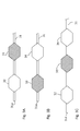
Fig. 1A bis 1D zeigen jeweils schematisch eine Phase des Einsatzes eineserfindungsgemäßen Ballonkatheters 10 in einem Gefäß V eines menschlichen (oder tierischen) Körpers.
-
Fig. 1A to 1D schematic representations for explaining a first embodiment of the invention, -
Fig. 2A to 2C schematic representations for explaining a second embodiment of the invention and -
Figs. 3A to 3C schematic representations for explaining further embodiments of the invention. -
Fig. 1A to 1D each show schematically a phase of the use of aballoon catheter 10 according to the invention in a vessel V of a human (or animal) body.
Der Ballonkatheter 10 umfasst einen langgestreckten Katheterkörper 11 mit einem distalen Ende 11a und einem proximalen Ende, welches außerhalb des Körpers und somit außerhalb des Darstellungsbereiches der Zeichnung liegt. Auf dem Katheterkörper 11 ist ein Ballon 13 angebracht, der im Ausgangszustand (
Während in
Hier ist auch dargestellt, dass ein distaler Abschnitt 13a des Ballons von einem proximalen Abschnitt 13b abgegrenzt ist, und zwar zur Verdeutlichung dessen, dass der distale Abschnitt 13a frei von einer Medikamentenbeschichtung ist. Mittels des Röntgenmarkierungsringes 17b ist die Grenze zwischen dem unbeschichteten distalen Ballonabschnitt 13a und dem beschichteten proximalen Abschnitt 13b auch für Röntgendarstellungsverfahren markiert. Die Spitze 15a ist hier stärker aufgeweitet als in dem in
Es ist zu erkennen, dass bei dem in den
Eine spezifische Ausgestaltung sieht vor, die Eigenschaften von expandiertem PTFE (e-PTFE) zu nutzen. Ein e-PTFE-Schlauch, der in seinem Aussendurchmesser dem schützenden Aussenschlauch entspricht, wird an diesem durch eine Klebeverbindung befestigt. e-PTFE lässt sich im Gegensatz zu anderen PTFE-Typen sehr leicht kleben, sofern Klebstoffe verwandt werden, welche niedrigviskos sind und die Fähigkeit besitzen unpolare Oberflächen zu benetzen. In diesem Falle erfolgt primär eine mechanische Verankerung der Mikrostruktur des e-PTFE mit dem penetrierenden Klebstoff. Es wird eine sehr zuverlässige Klebung/Verankerung des e-PTFE-Bauteiles mit dem Klebstoff erhalten.A specific embodiment envisages exploiting the properties of expanded PTFE (e-PTFE). An e-PTFE hose, which corresponds in its outside diameter to the protective outer hose, is attached to this by an adhesive bond. e-PTFE is very easy to glue, unlike other types of PTFE, when using adhesives that are low viscosity and have the ability to wet non-polar surfaces. In this case, there is primarily a mechanical anchoring of the microstructure of the e-PTFE with the penetrating adhesive. A very reliable bond / anchoring of the e-PTFE component with the adhesive is obtained.
In einem Beispiel kommen e-PTFE Schläuche der Firma Zeuss und der Cyanacrylat Klebstoff Loctite 4061 zum Einsatz. Der e-PTFE Schlauch wird mittels einer Telefonzange geweitet, um einen besseren Übergang von dem Schutzschlauch zu dem Tip-Segment zu realisieren. Alternativ kann statt von einem e-PTFE Schlauch natürlich auch von einer gerollten e-PTFE Folie ausgegangen werden. Die Verbindungsstelle wird mittels des Cyanacrylatklebers fixiert. Der Klebstoff Loctite 4061 benetzt den e-PTFE-Schlauch an den Kontaktstellen sehr gut und weist auch eine geeignete Viskosität auf, um die Porenstruktur des e-PTFE Schlauches zu infiltrieren.In one example, e-PTFE tubing from Zeuss and the cyanoacrylate adhesive Loctite 4061 are used. The e-PTFE tube is widened by means of a telephone pliers to make a better transition from the protective tube to the tip segment. Alternatively, of course, instead of an e-PTFE hose, a rolled e-PTFE film can also be assumed. The joint is fixed by means of the cyanoacrylate adhesive. The adhesive Loctite 4061 wets the e-PTFE tubing very well at the contact points and also has a suitable viscosity to infiltrate the pore structure of the e-PTFE tubing.
Der überstehende Bereich wird in einer Isopropanol-Stearinsäure-Lösung getränkt, um eine über die Stearinsäure-Konzentration gesteuerte Menge der Fettsäure durch einen Tauchprozess auf das PTFE zu übertragen. Diese Lösung ist ab einer Temperatur oberhalb des Schmelzpunktes der verwandten Fettsäure Stearinsäure stabil. Anschliessend wird der getränkte Bereich in Heissluft ≥ 80°C getrocknet. Im vorliegenden Fall sollte ebenfalls eine Temperatur höher als der Schmelzpunkt der Fettsäure genutzt werden, da diese eine hohe Kristallisationsneigung aufweist und bei zu geringer Temperatur einen kristallinen, wenig mit dem e-PTFE-Substrat verbundenen Niederschlag erzeugt.The supernatant is soaked in an isopropanol-stearic acid solution to transfer a stearic acid-controlled amount of the fatty acid to the PTFE by a dipping process. This solution is above a temperature above the melting point of the related fatty acid stearic acid stable. The impregnated area is then dried in hot air ≥ 80 ° C. In the present case, a temperature higher than the melting point of the fatty acid should also be used, as this has a high tendency to crystallize and at too low a temperature produces a crystalline, little associated with the e-PTFE substrate precipitate.
Bei diesem Prozessschritt wird das e-PTFE mittels der Stearinsäure infiltriert und wird über thermische Formprozesse formbar. Der erstellte Verbund kann nun mittels Temperaturen oberhalb des Schmelzpunktes der verwandten Fettsäure über Druck in eine temporäre Form gebracht werden.In this process step, the e-PTFE is infiltrated by means of stearic acid and is moldable by thermal molding processes. The created composite can now be pressurized into a temporary shape by means of temperatures above the melting point of the related fatty acid.
Unter Druck ist dieser Verbund relativ stabil, unter Zug delaminieren die PTFE Bereiche, und der e-PTFE Schlauch wird wieder freigesetzt. Je nach Herstellung des e-PTFE kann dieser noch verformbar sein. Die primär genutzten Eigenschaften sind jedoch die Ausbildung eines Verbundes, der unter Druckbelastung stabil ist und unter Zugbeanspruchungen in den mittels der Fettsäure "verklebten" Bereichen unter Zugbelastung leicht delaminiert. Der delaminierte Verbund weist geringe Reibung, je nach Formulierung auch eine gewisse Weichheit, auf, was diesen konstruktiven Bereich des Katheters auch atraumatisch macht.Under pressure, this bond is relatively stable, the PTFE regions delaminate under tension and the e-PTFE tube is released again. Depending on the production of the e-PTFE this may still be deformable. However, the primarily used properties are the formation of a composite that is stable under pressure and delays under tensile stress in the "glued" by the fatty acid areas under tensile load easily delaminated. The delaminated composite has low friction, depending on the formulation also a certain softness, which also makes this constructive area of the catheter atraumatic.
So sind Formulierungen möglich, die die Abformung des e-PTFE Verbundes zu einem atraumatischen geformten Tip oder Kathetersegmentes ermöglichen, welcher nach seiner plastischen Verformung keine bedenklich steifen und möglicherweise scharfkantige verformten Bereiche erzeugt. Solch ein Kathetersegment kann ohne Probleme durch eine enge Passage wie z.B. einen Introducer oder eine hemostatische Schleuse zurückgezogen werden, obwohl dieses Kathetersegment zuvor auf grössere Durchmesser verformt wurde.Thus, formulations are possible which allow the impression of the e-PTFE composite to form an atraumatic shaped tip or catheter segment which, after its plastic deformation, does not produce any dangerously stiff and possibly sharp-edged deformed regions. Such a catheter segment can easily be passed through a narrow passage such as e.g. an introducer or a hemostatic sheath are retracted, although this catheter segment has previously been deformed to larger diameters.
Durch seine wiedererlangte Weichheit schützt dieser Verbund nach der Verformung auch vor Schädigungen, welche durch Gefäßkontakt erzeugt werden können.Due to its regained softness, this composite protects after deformation from damage, which can be generated by vessel contact.
Bei vorliegender Applikation soll der Verbund eine Katheterspitze formen, welche von innen aufgedrückt wird (durch einen dilatierenden Ballon). Hierbei delaminieren die verklebten Bereiche des Verbundes unter der entstehenden Zugbelastung. Wird eine noch weiter expandierbare e-PTFE Membrantype verwandt, kann dieser Tip noch erheblich geweitet werden (nach derzeitigen Versuchen ca. um den Faktor 4 des Durchmessers). Durch die Deformation delaminiert auch die Mikrostruktur des e-PTFE-Verbundes, und die Membran erhält annähernd ihre ursprüngliche Weichheit wieder.In the present application, the composite is to form a catheter tip, which is pressed from the inside (by a dilating balloon). Here, the bonded areas of the composite delaminate under the resulting tensile load. If an even more expandable e-PTFE membrane type is used, this tip can be considerably widened (approx. 4 times the diameter according to current tests). The deformation also delaminates the microstructure of the e-PTFE composite, and the membrane almost recovers its original softness.
Bei der Verformung durch einen innenliegenden Ballon kann primär durch die Länge des verwandten e-PTFE Schlauches die Verformung so bemessen werden, dass durch die verformte Spitze ein schützender Trichter entsteht, der vor dem Durchmesser welcher einen Kontakt zur Gefässwand erzeugen würde, endet.In the case of deformation by means of an inner balloon, the deformation can be dimensioned primarily by the length of the related e-PTFE tube so that the deformed tip creates a protective funnel which ends before the diameter which would make contact with the vessel wall.
Vorteilhafte Nebeneffekte werden wie folgt zusammengefasst:
- Das Kathetersegment kann plastisch verformt werden. Diese Verformung erzeugt ein weiches, flexibles und somit auch atraumatisches Gebilde. Die durch die Umformung erzeugte Flexibilität dieses Konstruktes macht Deformation z.B. für den Rückzug und das weitere Handling des Katheters unproblematisch.
- Das e-PTFE und wie auch der Stearinsäure-beschichtete Verbund zeichnet sich durch eine reibungsarme Oberfläche aus.
- Unter dem Mikroskop ist eine minimale Partikelbildungen bei der Verwendung reiner Stearinsäure nachweisbar. Die Fixierung der Fettsäure in der PTFE Struktur und an der Oberfläche kann als sehr effektiv betrachtet werden. Durch Reduktion der Kristallinität dieses Bindesystemes - bei Stearinsäure z.B. durch Zumischung von Ölsäure - können Anforderungen an Partikelbildung und auch Reduktion der Verbundfestigkeit in einfacher Form optimiert werden.
- The catheter segment can be plastically deformed. This deformation creates a soft, flexible and therefore atraumatic structure. The flexibility of this construct generated by the deformation makes deformation, for example, for the withdrawal and further handling of the catheter unproblematic.
- The e-PTFE as well as the stearic acid-coated composite is characterized by a low-friction surface.
- Under the microscope, minimal particle formation is detectable using pure stearic acid. The fixation of the fatty acid in the PTFE structure and on the surface can be considered very effective. By reducing the crystallinity of this binding system - with stearic acid, for example, by admixing oleic acid - requirements for particle formation and reduction of bond strength in a simple form can be optimized.
Die Ausführung der Erfindung ist nicht auf die oben beschriebenen Beispiele und hervorgehobenen Aspekte beschränkt, sondern ebenso in einer Vielzahl von Abwandlungen möglich, die im Rahmen fachgemäßen Handelns liegen.The embodiment of the invention is not limited to the examples and highlighted aspects described above, but also possible in a variety of modifications, which are within the scope of technical action.
Claims (11)
Applications Claiming Priority (2)
| Application Number | Priority Date | Filing Date | Title |
|---|---|---|---|
| US201462050211P | 2014-09-15 | 2014-09-15 | |
| US201462050212P | 2014-09-15 | 2014-09-15 |
Publications (3)
| Publication Number | Publication Date |
|---|---|
| EP2995339A2 true EP2995339A2 (en) | 2016-03-16 |
| EP2995339A3 EP2995339A3 (en) | 2016-08-31 |
| EP2995339B1 EP2995339B1 (en) | 2020-01-08 |
Family
ID=53488242
Family Applications (2)
| Application Number | Title | Priority Date | Filing Date |
|---|---|---|---|
| EP15173650.1A Active EP2995339B1 (en) | 2014-09-15 | 2015-06-24 | Balloon catheter |
| EP15173651.9A Active EP3000446B1 (en) | 2014-09-15 | 2015-06-24 | Catheter system and method for producing same |
Family Applications After (1)
| Application Number | Title | Priority Date | Filing Date |
|---|---|---|---|
| EP15173651.9A Active EP3000446B1 (en) | 2014-09-15 | 2015-06-24 | Catheter system and method for producing same |
Country Status (2)
| Country | Link |
|---|---|
| US (2) | US20160074632A1 (en) |
| EP (2) | EP2995339B1 (en) |
Families Citing this family (1)
| Publication number | Priority date | Publication date | Assignee | Title |
|---|---|---|---|---|
| WO2018067875A1 (en) * | 2016-10-05 | 2018-04-12 | Microvention, Inc. | Balloon catheter systems |
Family Cites Families (21)
| Publication number | Priority date | Publication date | Assignee | Title |
|---|---|---|---|---|
| WO2003006096A1 (en) * | 2001-07-09 | 2003-01-23 | Argmed Kommanditbolag | Flow path control catheter with funnel-shaped expandable structure at proximal part and tubular-shaped structure at distal part and perfusion system with such a catheter |
| JP4351832B2 (en) * | 2002-08-05 | 2009-10-28 | テルモ株式会社 | Balloon catheter |
| US7468070B2 (en) * | 2004-01-23 | 2008-12-23 | Boston Scientific Scimed, Inc. | Stent delivery catheter |
| US8308789B2 (en) * | 2004-07-16 | 2012-11-13 | W. L. Gore & Associates, Inc. | Deployment system for intraluminal devices |
| US7892592B1 (en) * | 2004-11-30 | 2011-02-22 | Advanced Cardiovascular Systems, Inc. | Coating abluminal surfaces of stents and other implantable medical devices |
| US7632296B2 (en) * | 2005-03-03 | 2009-12-15 | Boston Scientific Scimed, Inc. | Rolling membrane with hydraulic recapture means for self expanding stent |
| US20080045896A1 (en) * | 2006-08-17 | 2008-02-21 | Abott Laboratories | Catheter having intermediate position markers |
| US8153181B2 (en) * | 2006-11-14 | 2012-04-10 | Boston Scientific Scimed, Inc. | Medical devices and related methods |
| US8690823B2 (en) * | 2007-07-13 | 2014-04-08 | Abbott Cardiovascular Systems Inc. | Drug coated balloon catheter |
| US20110137245A1 (en) * | 2007-09-12 | 2011-06-09 | Cook Medical Technologies Llc | Balloon catheter with embedded rod |
| EP2419167A1 (en) * | 2009-04-13 | 2012-02-22 | Cook Medical Technologies LLC | Coated balloon catheter |
| US9180274B2 (en) * | 2010-09-09 | 2015-11-10 | W. L. G ore & Associates, Inc | Indwelling luminal devices |
| US9327101B2 (en) * | 2010-09-17 | 2016-05-03 | Abbott Cardiovascular Systems Inc. | Length and diameter adjustable balloon catheter |
| EP2450010B1 (en) * | 2010-11-09 | 2013-11-20 | Biotronik AG | Balloon catheter, in particular for delivering drugs or stents in the region of a stenosis |
| EP2709711B8 (en) * | 2011-05-18 | 2017-03-22 | Vatrix Medical, Inc. | Coated balloons for blood vessel stabilization |
| EP2822635B8 (en) * | 2012-03-09 | 2018-11-14 | Clearstream Technologies Limited | Medical balloon with radiopaque identifier for precisely identifying the working surface |
| CN104968389B (en) * | 2012-12-31 | 2018-11-06 | 明讯科技有限公司 | Radiate impermeable foley's tube and the seal wire for facilitating alignment |
| EP2991718B1 (en) * | 2013-05-03 | 2019-11-13 | C.R. Bard, Inc. | Peelable protective sheath |
| WO2015059099A1 (en) * | 2013-10-22 | 2015-04-30 | Tulip Endovascular Innovation Limited | A therapeutic agent delivery system and method for arteries |
| US20150190618A1 (en) * | 2014-01-09 | 2015-07-09 | Medtronic Vascular, Inc. | Balloon Catheter With Elastomeric Sheath and Methods |
| US10569063B2 (en) * | 2014-10-03 | 2020-02-25 | W. L. Gore & Associates, Inc. | Removable covers for drug eluting medical devices |
-
2015
- 2015-06-24 EP EP15173650.1A patent/EP2995339B1/en active Active
- 2015-06-24 EP EP15173651.9A patent/EP3000446B1/en active Active
- 2015-08-12 US US14/824,257 patent/US20160074632A1/en not_active Abandoned
- 2015-08-17 US US14/827,871 patent/US20160074187A1/en not_active Abandoned
Non-Patent Citations (1)
| Title |
|---|
| None |
Also Published As
| Publication number | Publication date |
|---|---|
| EP2995339A3 (en) | 2016-08-31 |
| EP3000446A2 (en) | 2016-03-30 |
| US20160074632A1 (en) | 2016-03-17 |
| EP3000446B1 (en) | 2020-02-12 |
| EP3000446A3 (en) | 2016-04-20 |
| US20160074187A1 (en) | 2016-03-17 |
| EP2995339B1 (en) | 2020-01-08 |
Similar Documents
| Publication | Publication Date | Title |
|---|---|---|
| DE69737208T2 (en) | STENT MOUNTING DEVICE WITH A SEPARATE SHEATH | |
| DE60214973T2 (en) | DEVICE FOR IMPLANTING A STENT WITH LIQUID DISPENSER | |
| DE60110141T2 (en) | Stent delivery system with a delivery zone having a clear transition zone | |
| DE602004012640T2 (en) | Anti-friction agent for loading a self-expanding stent | |
| EP0592726B1 (en) | Catheter with a vessel support | |
| DE602004012037T2 (en) | Covering device for an aneurysm neck | |
| DE69626108T2 (en) | STENTING DEVICE WITH ROLLING MEMBRANE | |
| DE69434819T2 (en) | INSERTING A PROSTHESIS | |
| DE69825200T2 (en) | Catheter system for stent delivery | |
| EP2361651B1 (en) | System comprising a protective sleeve and a medical device, and method for the production thereof | |
| DE69228260T2 (en) | IMPREGNATED STENT | |
| DE602004010344T2 (en) | Catheter without balloon for inserting a stent | |
| EP4009918B1 (en) | Implant having a three-dimensional structure | |
| EP2710985A2 (en) | Implant, system formed of an implant and a catheter, and method for producing such a system | |
| EP2450010A1 (en) | Balloon catheter, in particular for delivering drugs or stents in the region of a stenosis | |
| DE9390115U1 (en) | Esophageal stent and delivery instrument | |
| EP1832309A2 (en) | Implantable medical electrode device, in particular cardiovascular pacemaker or defibrillator electrode device | |
| EP3151903B1 (en) | Balloon catheter with an insertion aid for a guide wire | |
| EP2522385B1 (en) | Elastic cap for the protection of the distal end of a catheter having an inner and an outer hose | |
| DE102015119639A1 (en) | Uterotubar implant device | |
| EP2995339B1 (en) | Balloon catheter | |
| DE60307808T2 (en) | Hybrid stent apparatus | |
| DE102008012744A1 (en) | Catheter and system for introducing an intraluminal endoprosthesis | |
| DE102022134125B4 (en) | CATHETER, BALLOON EXPANSION PROCEDURE, BALLOON COMPRESSION PROCEDURE | |
| EP2910221A1 (en) | Release device for releasing a medical implant from a catheter, and catheter comprising a release device |
Legal Events
| Date | Code | Title | Description |
|---|---|---|---|
| PUAI | Public reference made under article 153(3) epc to a published international application that has entered the european phase |
Free format text: ORIGINAL CODE: 0009012 |
|
| AK | Designated contracting states |
Kind code of ref document: A2 Designated state(s): AL AT BE BG CH CY CZ DE DK EE ES FI FR GB GR HR HU IE IS IT LI LT LU LV MC MK MT NL NO PL PT RO RS SE SI SK SM TR |
|
| AX | Request for extension of the european patent |
Extension state: BA ME |
|
| RIC1 | Information provided on ipc code assigned before grant |
Ipc: A61M 25/10 20060101AFI20160411BHEP |
|
| PUAL | Search report despatched |
Free format text: ORIGINAL CODE: 0009013 |
|
| AK | Designated contracting states |
Kind code of ref document: A3 Designated state(s): AL AT BE BG CH CY CZ DE DK EE ES FI FR GB GR HR HU IE IS IT LI LT LU LV MC MK MT NL NO PL PT RO RS SE SI SK SM TR |
|
| AX | Request for extension of the european patent |
Extension state: BA ME |
|
| RIC1 | Information provided on ipc code assigned before grant |
Ipc: A61M 25/10 20060101AFI20160726BHEP |
|
| STAA | Information on the status of an ep patent application or granted ep patent |
Free format text: STATUS: REQUEST FOR EXAMINATION WAS MADE |
|
| 17P | Request for examination filed |
Effective date: 20170223 |
|
| RBV | Designated contracting states (corrected) |
Designated state(s): AL AT BE BG CH CY CZ DE DK EE ES FI FR GB GR HR HU IE IS IT LI LT LU LV MC MK MT NL NO PL PT RO RS SE SI SK SM TR |
|
| GRAP | Despatch of communication of intention to grant a patent |
Free format text: ORIGINAL CODE: EPIDOSNIGR1 |
|
| STAA | Information on the status of an ep patent application or granted ep patent |
Free format text: STATUS: GRANT OF PATENT IS INTENDED |
|
| INTG | Intention to grant announced |
Effective date: 20190822 |
|
| GRAS | Grant fee paid |
Free format text: ORIGINAL CODE: EPIDOSNIGR3 |
|
| GRAA | (expected) grant |
Free format text: ORIGINAL CODE: 0009210 |
|
| STAA | Information on the status of an ep patent application or granted ep patent |
Free format text: STATUS: THE PATENT HAS BEEN GRANTED |
|
| AK | Designated contracting states |
Kind code of ref document: B1 Designated state(s): AL AT BE BG CH CY CZ DE DK EE ES FI FR GB GR HR HU IE IS IT LI LT LU LV MC MK MT NL NO PL PT RO RS SE SI SK SM TR |
|
| REG | Reference to a national code |
Ref country code: GB Ref legal event code: FG4D Free format text: NOT ENGLISH |
|
| REG | Reference to a national code |
Ref country code: CH Ref legal event code: EP |
|
| REG | Reference to a national code |
Ref country code: DE Ref legal event code: R096 Ref document number: 502015011439 Country of ref document: DE |
|
| REG | Reference to a national code |
Ref country code: IE Ref legal event code: FG4D Free format text: LANGUAGE OF EP DOCUMENT: GERMAN |
|
| REG | Reference to a national code |
Ref country code: AT Ref legal event code: REF Ref document number: 1221933 Country of ref document: AT Kind code of ref document: T Effective date: 20200215 |
|
| REG | Reference to a national code |
Ref country code: NL Ref legal event code: FP |
|
| REG | Reference to a national code |
Ref country code: LT Ref legal event code: MG4D |
|
| PG25 | Lapsed in a contracting state [announced via postgrant information from national office to epo] |
Ref country code: NO Free format text: LAPSE BECAUSE OF FAILURE TO SUBMIT A TRANSLATION OF THE DESCRIPTION OR TO PAY THE FEE WITHIN THE PRESCRIBED TIME-LIMIT Effective date: 20200408 Ref country code: LT Free format text: LAPSE BECAUSE OF FAILURE TO SUBMIT A TRANSLATION OF THE DESCRIPTION OR TO PAY THE FEE WITHIN THE PRESCRIBED TIME-LIMIT Effective date: 20200108 Ref country code: PT Free format text: LAPSE BECAUSE OF FAILURE TO SUBMIT A TRANSLATION OF THE DESCRIPTION OR TO PAY THE FEE WITHIN THE PRESCRIBED TIME-LIMIT Effective date: 20200531 Ref country code: RS Free format text: LAPSE BECAUSE OF FAILURE TO SUBMIT A TRANSLATION OF THE DESCRIPTION OR TO PAY THE FEE WITHIN THE PRESCRIBED TIME-LIMIT Effective date: 20200108 Ref country code: FI Free format text: LAPSE BECAUSE OF FAILURE TO SUBMIT A TRANSLATION OF THE DESCRIPTION OR TO PAY THE FEE WITHIN THE PRESCRIBED TIME-LIMIT Effective date: 20200108 |
|
| PG25 | Lapsed in a contracting state [announced via postgrant information from national office to epo] |
Ref country code: HR Free format text: LAPSE BECAUSE OF FAILURE TO SUBMIT A TRANSLATION OF THE DESCRIPTION OR TO PAY THE FEE WITHIN THE PRESCRIBED TIME-LIMIT Effective date: 20200108 Ref country code: GR Free format text: LAPSE BECAUSE OF FAILURE TO SUBMIT A TRANSLATION OF THE DESCRIPTION OR TO PAY THE FEE WITHIN THE PRESCRIBED TIME-LIMIT Effective date: 20200409 Ref country code: SE Free format text: LAPSE BECAUSE OF FAILURE TO SUBMIT A TRANSLATION OF THE DESCRIPTION OR TO PAY THE FEE WITHIN THE PRESCRIBED TIME-LIMIT Effective date: 20200108 Ref country code: LV Free format text: LAPSE BECAUSE OF FAILURE TO SUBMIT A TRANSLATION OF THE DESCRIPTION OR TO PAY THE FEE WITHIN THE PRESCRIBED TIME-LIMIT Effective date: 20200108 Ref country code: IS Free format text: LAPSE BECAUSE OF FAILURE TO SUBMIT A TRANSLATION OF THE DESCRIPTION OR TO PAY THE FEE WITHIN THE PRESCRIBED TIME-LIMIT Effective date: 20200508 Ref country code: BG Free format text: LAPSE BECAUSE OF FAILURE TO SUBMIT A TRANSLATION OF THE DESCRIPTION OR TO PAY THE FEE WITHIN THE PRESCRIBED TIME-LIMIT Effective date: 20200408 |
|
| REG | Reference to a national code |
Ref country code: DE Ref legal event code: R097 Ref document number: 502015011439 Country of ref document: DE |
|
| PG25 | Lapsed in a contracting state [announced via postgrant information from national office to epo] |
Ref country code: CZ Free format text: LAPSE BECAUSE OF FAILURE TO SUBMIT A TRANSLATION OF THE DESCRIPTION OR TO PAY THE FEE WITHIN THE PRESCRIBED TIME-LIMIT Effective date: 20200108 Ref country code: ES Free format text: LAPSE BECAUSE OF FAILURE TO SUBMIT A TRANSLATION OF THE DESCRIPTION OR TO PAY THE FEE WITHIN THE PRESCRIBED TIME-LIMIT Effective date: 20200108 Ref country code: RO Free format text: LAPSE BECAUSE OF FAILURE TO SUBMIT A TRANSLATION OF THE DESCRIPTION OR TO PAY THE FEE WITHIN THE PRESCRIBED TIME-LIMIT Effective date: 20200108 Ref country code: EE Free format text: LAPSE BECAUSE OF FAILURE TO SUBMIT A TRANSLATION OF THE DESCRIPTION OR TO PAY THE FEE WITHIN THE PRESCRIBED TIME-LIMIT Effective date: 20200108 Ref country code: SM Free format text: LAPSE BECAUSE OF FAILURE TO SUBMIT A TRANSLATION OF THE DESCRIPTION OR TO PAY THE FEE WITHIN THE PRESCRIBED TIME-LIMIT Effective date: 20200108 Ref country code: DK Free format text: LAPSE BECAUSE OF FAILURE TO SUBMIT A TRANSLATION OF THE DESCRIPTION OR TO PAY THE FEE WITHIN THE PRESCRIBED TIME-LIMIT Effective date: 20200108 Ref country code: SK Free format text: LAPSE BECAUSE OF FAILURE TO SUBMIT A TRANSLATION OF THE DESCRIPTION OR TO PAY THE FEE WITHIN THE PRESCRIBED TIME-LIMIT Effective date: 20200108 |
|
| PLBE | No opposition filed within time limit |
Free format text: ORIGINAL CODE: 0009261 |
|
| STAA | Information on the status of an ep patent application or granted ep patent |
Free format text: STATUS: NO OPPOSITION FILED WITHIN TIME LIMIT |
|
| 26N | No opposition filed |
Effective date: 20201009 |
|
| PG25 | Lapsed in a contracting state [announced via postgrant information from national office to epo] |
Ref country code: IT Free format text: LAPSE BECAUSE OF FAILURE TO SUBMIT A TRANSLATION OF THE DESCRIPTION OR TO PAY THE FEE WITHIN THE PRESCRIBED TIME-LIMIT Effective date: 20200108 Ref country code: MC Free format text: LAPSE BECAUSE OF FAILURE TO SUBMIT A TRANSLATION OF THE DESCRIPTION OR TO PAY THE FEE WITHIN THE PRESCRIBED TIME-LIMIT Effective date: 20200108 |
|
| PG25 | Lapsed in a contracting state [announced via postgrant information from national office to epo] |
Ref country code: PL Free format text: LAPSE BECAUSE OF FAILURE TO SUBMIT A TRANSLATION OF THE DESCRIPTION OR TO PAY THE FEE WITHIN THE PRESCRIBED TIME-LIMIT Effective date: 20200108 Ref country code: SI Free format text: LAPSE BECAUSE OF FAILURE TO SUBMIT A TRANSLATION OF THE DESCRIPTION OR TO PAY THE FEE WITHIN THE PRESCRIBED TIME-LIMIT Effective date: 20200108 |
|
| GBPC | Gb: european patent ceased through non-payment of renewal fee |
Effective date: 20200624 |
|
| PG25 | Lapsed in a contracting state [announced via postgrant information from national office to epo] |
Ref country code: LU Free format text: LAPSE BECAUSE OF NON-PAYMENT OF DUE FEES Effective date: 20200624 |
|
| REG | Reference to a national code |
Ref country code: BE Ref legal event code: MM Effective date: 20200630 |
|
| PG25 | Lapsed in a contracting state [announced via postgrant information from national office to epo] |
Ref country code: GB Free format text: LAPSE BECAUSE OF NON-PAYMENT OF DUE FEES Effective date: 20200624 |
|
| PG25 | Lapsed in a contracting state [announced via postgrant information from national office to epo] |
Ref country code: BE Free format text: LAPSE BECAUSE OF NON-PAYMENT OF DUE FEES Effective date: 20200630 |
|
| REG | Reference to a national code |
Ref country code: AT Ref legal event code: MM01 Ref document number: 1221933 Country of ref document: AT Kind code of ref document: T Effective date: 20200624 |
|
| PG25 | Lapsed in a contracting state [announced via postgrant information from national office to epo] |
Ref country code: AT Free format text: LAPSE BECAUSE OF NON-PAYMENT OF DUE FEES Effective date: 20200624 |
|
| PG25 | Lapsed in a contracting state [announced via postgrant information from national office to epo] |
Ref country code: TR Free format text: LAPSE BECAUSE OF FAILURE TO SUBMIT A TRANSLATION OF THE DESCRIPTION OR TO PAY THE FEE WITHIN THE PRESCRIBED TIME-LIMIT Effective date: 20200108 Ref country code: MT Free format text: LAPSE BECAUSE OF FAILURE TO SUBMIT A TRANSLATION OF THE DESCRIPTION OR TO PAY THE FEE WITHIN THE PRESCRIBED TIME-LIMIT Effective date: 20200108 Ref country code: CY Free format text: LAPSE BECAUSE OF FAILURE TO SUBMIT A TRANSLATION OF THE DESCRIPTION OR TO PAY THE FEE WITHIN THE PRESCRIBED TIME-LIMIT Effective date: 20200108 |
|
| PG25 | Lapsed in a contracting state [announced via postgrant information from national office to epo] |
Ref country code: MK Free format text: LAPSE BECAUSE OF FAILURE TO SUBMIT A TRANSLATION OF THE DESCRIPTION OR TO PAY THE FEE WITHIN THE PRESCRIBED TIME-LIMIT Effective date: 20200108 Ref country code: AL Free format text: LAPSE BECAUSE OF FAILURE TO SUBMIT A TRANSLATION OF THE DESCRIPTION OR TO PAY THE FEE WITHIN THE PRESCRIBED TIME-LIMIT Effective date: 20200108 |
|
| PGFP | Annual fee paid to national office [announced via postgrant information from national office to epo] |
Ref country code: NL Payment date: 20220621 Year of fee payment: 8 Ref country code: IE Payment date: 20220616 Year of fee payment: 8 |
|
| P01 | Opt-out of the competence of the unified patent court (upc) registered |
Effective date: 20230607 |
|
| REG | Reference to a national code |
Ref country code: NL Ref legal event code: MM Effective date: 20230701 |
|
| REG | Reference to a national code |
Ref country code: IE Ref legal event code: MM4A |
|
| PG25 | Lapsed in a contracting state [announced via postgrant information from national office to epo] |
Ref country code: NL Free format text: LAPSE BECAUSE OF NON-PAYMENT OF DUE FEES Effective date: 20230701 |
|
| PG25 | Lapsed in a contracting state [announced via postgrant information from national office to epo] |
Ref country code: IE Free format text: LAPSE BECAUSE OF NON-PAYMENT OF DUE FEES Effective date: 20230624 |
|
| PG25 | Lapsed in a contracting state [announced via postgrant information from national office to epo] |
Ref country code: IE Free format text: LAPSE BECAUSE OF NON-PAYMENT OF DUE FEES Effective date: 20230624 |
|
| PGFP | Annual fee paid to national office [announced via postgrant information from national office to epo] |
Ref country code: DE Payment date: 20250618 Year of fee payment: 11 |
|
| PGFP | Annual fee paid to national office [announced via postgrant information from national office to epo] |
Ref country code: FR Payment date: 20250626 Year of fee payment: 11 |
|
| REG | Reference to a national code |
Ref country code: DE Ref legal event code: R082 Ref document number: 502015011439 Country of ref document: DE Representative=s name: WSL PATENTANWAELTE PARTNERSCHAFT MBB, DE |
|
| PGFP | Annual fee paid to national office [announced via postgrant information from national office to epo] |
Ref country code: CH Payment date: 20250701 Year of fee payment: 11 |