EP2995366A1 - Vorrichtung zur abscheidung von kohlendioxid unter verwendung einer silikontrennfolie und verfahren zur herstellung davon - Google Patents
Vorrichtung zur abscheidung von kohlendioxid unter verwendung einer silikontrennfolie und verfahren zur herstellung davon Download PDFInfo
- Publication number
- EP2995366A1 EP2995366A1 EP14794902.8A EP14794902A EP2995366A1 EP 2995366 A1 EP2995366 A1 EP 2995366A1 EP 14794902 A EP14794902 A EP 14794902A EP 2995366 A1 EP2995366 A1 EP 2995366A1
- Authority
- EP
- European Patent Office
- Prior art keywords
- carbon dioxide
- membrane
- byproduct gas
- separation
- porous silicone
- Prior art date
- Legal status (The legal status is an assumption and is not a legal conclusion. Google has not performed a legal analysis and makes no representation as to the accuracy of the status listed.)
- Withdrawn
Links
Images


Classifications
-
- B—PERFORMING OPERATIONS; TRANSPORTING
- B01—PHYSICAL OR CHEMICAL PROCESSES OR APPARATUS IN GENERAL
- B01D—SEPARATION
- B01D53/00—Separation of gases or vapours; Recovering vapours of volatile solvents from gases; Chemical or biological purification of waste gases, e.g. engine exhaust gases, smoke, fumes, flue gases, aerosols
- B01D53/22—Separation of gases or vapours; Recovering vapours of volatile solvents from gases; Chemical or biological purification of waste gases, e.g. engine exhaust gases, smoke, fumes, flue gases, aerosols by diffusion
-
- B—PERFORMING OPERATIONS; TRANSPORTING
- B01—PHYSICAL OR CHEMICAL PROCESSES OR APPARATUS IN GENERAL
- B01D—SEPARATION
- B01D53/00—Separation of gases or vapours; Recovering vapours of volatile solvents from gases; Chemical or biological purification of waste gases, e.g. engine exhaust gases, smoke, fumes, flue gases, aerosols
- B01D53/22—Separation of gases or vapours; Recovering vapours of volatile solvents from gases; Chemical or biological purification of waste gases, e.g. engine exhaust gases, smoke, fumes, flue gases, aerosols by diffusion
- B01D53/228—Separation of gases or vapours; Recovering vapours of volatile solvents from gases; Chemical or biological purification of waste gases, e.g. engine exhaust gases, smoke, fumes, flue gases, aerosols by diffusion characterised by specific membranes
-
- B—PERFORMING OPERATIONS; TRANSPORTING
- B01—PHYSICAL OR CHEMICAL PROCESSES OR APPARATUS IN GENERAL
- B01D—SEPARATION
- B01D53/00—Separation of gases or vapours; Recovering vapours of volatile solvents from gases; Chemical or biological purification of waste gases, e.g. engine exhaust gases, smoke, fumes, flue gases, aerosols
- B01D53/22—Separation of gases or vapours; Recovering vapours of volatile solvents from gases; Chemical or biological purification of waste gases, e.g. engine exhaust gases, smoke, fumes, flue gases, aerosols by diffusion
- B01D53/225—Multiple stage diffusion
-
- B—PERFORMING OPERATIONS; TRANSPORTING
- B01—PHYSICAL OR CHEMICAL PROCESSES OR APPARATUS IN GENERAL
- B01D—SEPARATION
- B01D69/00—Semi-permeable membranes for separation processes or apparatus characterised by their form, structure or properties; Manufacturing processes specially adapted therefor
- B01D69/12—Composite membranes; Ultra-thin membranes
-
- B—PERFORMING OPERATIONS; TRANSPORTING
- B01—PHYSICAL OR CHEMICAL PROCESSES OR APPARATUS IN GENERAL
- B01D—SEPARATION
- B01D71/00—Semi-permeable membranes for separation processes or apparatus characterised by the material; Manufacturing processes specially adapted therefor
- B01D71/06—Organic material
- B01D71/70—Polymers having silicon in the main chain, with or without sulfur, nitrogen, oxygen or carbon only
-
- B—PERFORMING OPERATIONS; TRANSPORTING
- B01—PHYSICAL OR CHEMICAL PROCESSES OR APPARATUS IN GENERAL
- B01D—SEPARATION
- B01D53/00—Separation of gases or vapours; Recovering vapours of volatile solvents from gases; Chemical or biological purification of waste gases, e.g. engine exhaust gases, smoke, fumes, flue gases, aerosols
- B01D53/22—Separation of gases or vapours; Recovering vapours of volatile solvents from gases; Chemical or biological purification of waste gases, e.g. engine exhaust gases, smoke, fumes, flue gases, aerosols by diffusion
- B01D2053/221—Devices
-
- B—PERFORMING OPERATIONS; TRANSPORTING
- B01—PHYSICAL OR CHEMICAL PROCESSES OR APPARATUS IN GENERAL
- B01D—SEPARATION
- B01D53/00—Separation of gases or vapours; Recovering vapours of volatile solvents from gases; Chemical or biological purification of waste gases, e.g. engine exhaust gases, smoke, fumes, flue gases, aerosols
- B01D53/22—Separation of gases or vapours; Recovering vapours of volatile solvents from gases; Chemical or biological purification of waste gases, e.g. engine exhaust gases, smoke, fumes, flue gases, aerosols by diffusion
- B01D2053/221—Devices
- B01D2053/223—Devices with hollow tubes
-
- B—PERFORMING OPERATIONS; TRANSPORTING
- B01—PHYSICAL OR CHEMICAL PROCESSES OR APPARATUS IN GENERAL
- B01D—SEPARATION
- B01D2256/00—Main component in the product gas stream after treatment
- B01D2256/24—Hydrocarbons
- B01D2256/245—Methane
-
- B—PERFORMING OPERATIONS; TRANSPORTING
- B01—PHYSICAL OR CHEMICAL PROCESSES OR APPARATUS IN GENERAL
- B01D—SEPARATION
- B01D2257/00—Components to be removed
- B01D2257/50—Carbon oxides
- B01D2257/504—Carbon dioxide
-
- B—PERFORMING OPERATIONS; TRANSPORTING
- B01—PHYSICAL OR CHEMICAL PROCESSES OR APPARATUS IN GENERAL
- B01D—SEPARATION
- B01D2258/00—Sources of waste gases
- B01D2258/02—Other waste gases
- B01D2258/0283—Flue gases
-
- B—PERFORMING OPERATIONS; TRANSPORTING
- B01—PHYSICAL OR CHEMICAL PROCESSES OR APPARATUS IN GENERAL
- B01D—SEPARATION
- B01D2259/00—Type of treatment
- B01D2259/80—Employing electric, magnetic, electromagnetic or wave energy, or particle radiation
-
- B—PERFORMING OPERATIONS; TRANSPORTING
- B01—PHYSICAL OR CHEMICAL PROCESSES OR APPARATUS IN GENERAL
- B01D—SEPARATION
- B01D2259/00—Type of treatment
- B01D2259/80—Employing electric, magnetic, electromagnetic or wave energy, or particle radiation
- B01D2259/816—Sonic or ultrasonic vibration
-
- Y—GENERAL TAGGING OF NEW TECHNOLOGICAL DEVELOPMENTS; GENERAL TAGGING OF CROSS-SECTIONAL TECHNOLOGIES SPANNING OVER SEVERAL SECTIONS OF THE IPC; TECHNICAL SUBJECTS COVERED BY FORMER USPC CROSS-REFERENCE ART COLLECTIONS [XRACs] AND DIGESTS
- Y02—TECHNOLOGIES OR APPLICATIONS FOR MITIGATION OR ADAPTATION AGAINST CLIMATE CHANGE
- Y02C—CAPTURE, STORAGE, SEQUESTRATION OR DISPOSAL OF GREENHOUSE GASES [GHG]
- Y02C20/00—Capture or disposal of greenhouse gases
- Y02C20/40—Capture or disposal of greenhouse gases of CO2
Definitions
- the present invention relates to an apparatus for separating carbon dioxide from waste gas, and more particularly, to an apparatus for separating carbon dioxide using a separator, which is made of a ceramic-coated porous silicone membrane, and a method of manufacturing the same.
- Global warming is now an issue of worldwide concern, and the greenhouse effect caused by carbon dioxide and methane gas plays a significant role in global warming. Global warming not only disturbs the ecosystem but also has a huge impact on human social life. In this regard, efforts are being made in various aspects to reduce atmospheric emissions of carbon dioxide and methane gas.
- landfill gas In sewage treatment plants, waste water treatment plants, landfill sites, etc., organic substances contained in waste generate gas through decomposition. This gas is called landfill gas.
- This gas is called landfill gas.
- the landfill gas At the initial landfill stage, the landfill gas is decomposed in the presence of oxygen. However, as oxygen is gradually reduced, the landfill gas is primarily decomposed in an anaerobic digestion process. Most of the landfill gas generated in the anaerobic digestion process contains 40 to 60 % carbon dioxide, 45 to 60 % methane gas, and very small amounts of other components such as nitrogen and ammonia. Methane and carbon dioxide, which are main components of the landfill gas, are the causes of global warming. To make the landfill gas industrially applicable, methane gas and carbon dioxide should be separated from each other.
- Carbon dioxide is emitted from sewage treatment plants, waste water treatment plants, landfill sites, etc. when waste materials are burned. Carbon dioxide is particularly a problem when emitted from thermoelectric power plants or steel mills. Therefore, technologies of separating and removing carbon dioxide from generated waste gas are being developed. Some carbon dioxide separation technologies already developed include an absorption method, an adsorption method, a cryogenic air separation method, and a membrane separation method.
- the absorption method is a method of selectively separating carbon dioxide by absorbing carbon dioxide.
- a combustion or process gas that contains carbon dioxide is brought into contact with a solution, such that carbon dioxide can be absorbed by a chemical reaction.
- a wet amine method is commercially available technology.
- carbon dioxide is collected from a combustion exhaust gas using an amine-based absorbent.
- the adsorption method is a method of separating carbon dioxide by making carbon dioxide be physically adsorbed onto the surface of an adsorbent having affinity for carbon dioxide.
- the cryogenic air separation method is a classic gas-liquid separation method for separating carbon dioxide liquefied at low temperature from other gases not liquefied. This method is advantageous in that it can produce a large amount of liquefied carbon dioxide but disadvantageous in that it requires a lot of energy for cooling.
- the membrane separation method generally uses a solid membrane having a separation function.
- the membrane separation method is widely usable from the molecular level to the particle level depending on the type of membrane used.
- a material is usually separated using pressure which is mechanical energy, less energy is consumed in the membrane separation method than in a distillation method using thermal energy.
- Applied examples of the membrane separation method include reverse osmosis, ultrafiltration, precision filtration, dialysis, and gas separation.
- the gas separation method is drawing attention as a method of separating and collecting carbon dioxide in an energy-saving manner from large-scale sources of carbon dioxide such as thermoelectric power plants, cement plants, and steel mill furnaces.
- a gas separation membrane that can be used in the membrane separation method to separate and collect a particular gas from, e.g., natural gas, may be an aromatic polyimide membrane which is obtained by polymerizing and imidizing an aromatic tetracarboxylic acid component and an aromatic diamine component.
- an aromatic polyimide membrane which is obtained by polymerizing and imidizing an aromatic tetracarboxylic acid component and an aromatic diamine component.
- Research has been actively conducted on the aromatic polyimide membrane.
- the aromatic polyimide gas separation membrane can be manufactured only at a high temperature of 350 °C or above and has problems in heat resistance, durability, and chemical resistance. Therefore, solutions to these problems need to be researched.
- Korean Patent Publication No. 10-0734926 discloses an apparatus for removing a sulfur compound and separating methane and carbon dioxide using a liquid iron chelate catalyst.
- the apparatus can process a sulfur compound in a bad-smelling gas generated by a landfill site or an anaerobic digester and separate and collect methane and carbon dioxide in the gas.
- Japanese Patent Laid-Open Publication No. hei 10-180062 discloses a separation membrane and a selective separation method.
- the separation membrane can separate carbon dioxide from a mixture of carbon dioxide and methane using a dense membrane or an asymmetric membrane that contains, as its main component, fluorine-containing polyimide resin having high separability and permeability for carbon dioxide.
- aspects of the present invention provide an apparatus for selectively separating and collecting carbon dioxide from a byproduct gas (methane gas, carbon dioxide and other gases will collectively be referred to as ⁇ byproduct gas') using a separator or plate made of a porous silicone membrane.
- a byproduct gas methane gas, carbon dioxide and other gases will collectively be referred to as ⁇ byproduct gas'
- aspects of the present invention also provide a method of efficiently separating carbon dioxide by simplifying a separation membrane manufacturing process and a separation process thereby to increase the size of a separation apparatus and reduce energy needed to separate carbon dioxide.
- an apparatus for separating carbon dioxide includes: a byproduct gas storage tank which stores a byproduct gas generated by a basic environmental treatment facility and containing a large amount of methane and carbon dioxide; a byproduct gas inlet through which the byproduct gas is fed from the byproduct gas storage tank and a byproduct gas outlet through which a methane-containing byproduct gas obtained by separating carbon dioxide from the fed byproduct gas is discharged; a separation container which includes a separator made of a porous silicone membrane that separates carbon dioxide from the fed byproduct gas; a discharge pipe which is formed in the separation container to discharge carbon dioxide separated from the porous silicone membrane; a carbon dioxide storage tank which receives and stores the separated carbon dioxide; and a remaining byproduct gas storage tank which stores the methane-containing byproduct gas obtained by separating carbon dioxide from the fed byproduct gas.
- a carbon dioxide separation membrane including: a separation membrane which is made of porous silicone; and a coated layer which is obtained by coating nanoceramic powder on the porous silicone separation membrane.
- a method of separating carbon dioxide from a byproduct gas using an apparatus for separating carbon dioxide which includes a carbon dioxide separation membrane is provided.
- a separator or plate made of a ceramic-coated porous silicone membrane is used. Therefore, carbon dioxide can be selectively separated from a byproduct gas using a very small pressure difference and a simple method.
- a conventional apparatus for separating carbon dioxide uses a pressure difference. That is, the conventional apparatus for separating carbon dioxide separates carbon dioxide by feeding a mixed gas into a pressure of 3 to 40 kgf/cm 2 or a higher pressure. Therefore, high energy consumption is required. In addition, since there is a limit to increasing the size of the apparatus, there is a limit to production. However, the present invention operates an apparatus for separating carbon dioxide at room temperature by maintaining a difference in pressure between the inside and outside of a separation membrane at less than 4 kgf/cm 2 . Therefore, energy consumption is low. Further, since the apparatus is simple, the product cost of the apparatus can be saved.
- the present invention discloses an apparatus for separating carbon dioxide.
- the apparatus includes: a byproduct gas storage tank which stores a byproduct gas generated by a basic environmental treatment facility and containing a large amount of methane and carbon dioxide; a byproduct gas inlet through which the byproduct gas is fed from the byproduct gas storage tank and a byproduct gas outlet through which a methane-containing byproduct gas obtained by separating carbon dioxide from the fed byproduct gas is discharged; a separation container which includes a separator made of a porous silicone membrane that separates carbon dioxide from the fed byproduct gas; a discharge pipe which is formed in the separation container to discharge carbon dioxide separated from the porous silicone membrane; a carbon dioxide storage tank which receives and stores the separated carbon dioxide; and a storage tank which stores the methane-containing byproduct gas obtained by separating carbon dioxide from the fed byproduct gas.
- a gas separation membrane method is used to separate a specific component from a mixed gas or organic vapor by using permeation of a gas through a membrane.
- gas components diffuse through the membrane by being dissolved or adsorbed into the membrane.
- solubility and permeability of each gas component may vary according to the material of the separation membrane.
- carbon dioxide, water vapor, helium, and hydrogen sulfide can easily permeate through a membrane by being easily adsorbed or dissolved into the membrane
- nitrogen, methane, ethane and other hydrocarbons are gas components that permeate through the membrane at very low speed. This is a basic reason why a membrane is used to separate oxygen from nitrogen and carbon dioxide from methane in the air.
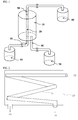
- FIG. 1 is a schematic view of an apparatus for separating carbon dioxide from a byproduct gas according to an embodiment of the present invention.
- An apparatus for separating and collecting carbon dioxide includes a byproduct gas storage tank 60 which stores a byproduct gas that contains a large amount of methane and carbon dioxide, a byproduct gas inlet 30 through which the byproduct gas is fed from the byproduct gas storage tank 60, a byproduct gas outlet 50 through which a methane-containing byproduct gas obtained by separating carbon dioxide from the fed byproduct gas is discharged, a separation container 10 which includes a separator 20 for separating carbon dioxide from the fed byproduct gas, a discharge pipe 40 through which the separated carbon dioxide is discharged from the separation container, a carbon dioxide storage tank 70 which receives and stores the separated carbon dioxide, and a tank 80 which receives and stores the methane-containing byproduct gas obtained by separating carbon dioxide from the fed byproduct gas.
- the gas separation membrane method when used to separate a specific gas, it is required to increase pressure at the feed side and reduce pressure at the permeate side, so that the gas can permeate through a separation membrane effectively.
- the present invention uses a difference in negative pressure applied to the inside and outside of a separation membrane, which is installed in the separation container, for a specific gas component.
- the separation container may be maintained at a temperature of 0 to 60 °C, more preferably, in a low temperature range of 20 to 40 °C.
- the separation container may be a carbon dioxide separation apparatus which undergoes no phase change by maintaining a pressure of 0 to 4 kgf/cm 2 and has low energy consumption.
- carbon dioxide can be separated more efficiently by an osmotic pressure phenomenon resulting from a difference between the concentration of carbon dioxide contained in a byproduct gas and the concentration of carbon dioxide separated from the byproduct gas. Even when the concentration of carbon dioxide is the same inside and outside the separate pipe, the separation of carbon dioxide may be continued by the difference in negative pressure.
- the separation container 10 of the present invention can obtain energy required to separate carbon dioxide from the difference in carbon dioxide concentration between the inside D1 of the separation membrane made of a porous silicone membrane and the outside D2 of the separator.
- a byproduct gas flows inside D1 the separator, and only carbon dioxide separated from the byproduct gas exists outside D2 the separator.
- initial pressure P1 by which a byproduct gas is fed into the separator 20 is greater than or equal to pressure P2 inside the separator, carbon dioxide permeates through the porous silicone membrane in any situation if carbon dioxide concentration of D1 is greater than that of D2.
- the separated carbon dioxide is periodically transported to the carbon dioxide storage tank in order to prevent carbon dioxide concentration of D2 from becoming greater than that of D1. In this way, carbon dioxide can be selectively separated by continuously permeating through the porous silicone membrane. As a result, high-purity carbon dioxide can be obtained.
- a pump may be installed at the outlet to facilitate the discharge of the methane-containing byproduct gas without carbon dioxide through the outlet.
- the pump may be maintained at a pressure of 0 to 2 kgf/cm 2 in order to maintain a pressure difference within the separation container in a range of 0 to 4 kgf/cm 2 .
- another pump may be installed at a carbon dioxide collection line in order for efficient collection of separated carbon dioxide.
- the pump may be maintained at a pressure of approximately 0 to -1 kgf/cm 2 .
- the separation membrane may be made of a polymer material such as cellulose acetate or polysulfone, a new polymer material, a ceramic material or a carbon molecular sieve material.
- the separation membrane may be made of porous silica-based ceramics, porous silica-based glass, porous alumina-based ceramics, porous stainless steel, porous titanium, or porous silver. More preferably, the separation membrane may be made of porous silicone.
- the separator 20 made of the porous silicone membrane may be in the form of a vertical sheet, a horizontal sheet, or a tube. More preferably, the separator 20 may be in the form of a tube.
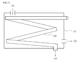
- FIGS. 2 and 3 illustrate different embodiments in which a byproduct gas is fed into either the separator 20 or the separation container 10 using reversible characteristics of a separator.
- FIG. 2 illustrates a case where when a byproduct gas fed into the separator 20 as indicated by reference numeral 30 flows through the separator 20, carbon dioxide is adsorbed and passed through the separation membrane to be collected in the separation container 10 as indicated by reference numeral 40.
- FIG. 3 illustrates a case where when a byproduct gas fed into the separation container 10 as indicated by reference numeral 30 is absorbed and permeates into the separator to be discharged as indicated by reference numeral 40.
- FIG. 4 illustrates a separation container having a plurality of separators in the form of tubes and a separation container lid.
- a plurality of separators 20 may be installed in a separation container 10 as illustrated in FIG. 4 .
- the separators can be installed at a desired angle, e.g., vertically or horizontally, and a large-scale apparatus for separating carbon dioxide can be manufactured by connecting two or more separation containers 10.
- a support 90 may be installed at appropriate locations to support and protect the separators.
- the porous silicone membrane of the present invention can be manufactured in the form of a sheet to produce a box-type separator with an increased separation area. Accordingly, the amount of carbon dioxide separated and collected can be increased.
- FIG. 5 illustrates a separator 20 having a surface area increased by installing separation membranes, which are manufactured in the form of sheets, to face each other with an empty space therebetween.
- the separator includes a support 90 shaped like a quadrilateral frame. The support 90 maintains a predetermined gap between the separation membranes.
- FIG. 6(A) illustrates a box-type separator which extends along a lengthwise direction thereof and in which a support 90 and a mesh 100 are installed between separation membranes 20 to maintain a predetermined gap between the separation membranes 20, protect the separation membranes 20 and allow carbon dioxide to be separated.
- FIG. 6(B) illustrates the support 90 only.
- the support 90 supports the mesh 100 to suppress excessive expansion of the separation membranes 20.
- FIG. 6(C) illustrates the mesh 100 only.
- the mesh 100 is a structure that suppresses excessive expansion of the separation membranes 20 due to a difference in pressure between the inside and outside of the separator in the process of separating carbon dioxide and maintains a predetermined gap between the separation membranes.
- a plurality of box-type separators 20 are installed in a separation container 10.
- a byproduct gas is injected from outside the separators 20, and carbon dioxide is discharged and collected from each of the separators 20 through a discharge pipe 40.
- a through hole may be formed in each of the separators 20 to directly connect the separators 20 by compression.
- carbon dioxide may be collected along the through holes, or a carbon dioxide connection pipe may be installed between the separators. Since a separator is reversible, a byproduct gas may be injected into a separator, and separated carbon dioxide may be collected outside the separator.
- FIG. 7 illustrates nanoceramic coated on the surface of a separation membrane.
- ceramic nano-powder may be coated on the inside and outside of the porous silicone separation membrane.
- Ceramic may be any one or more of Fe-based oxide, Pd-based oxide, Ti-base oxide, and Al-based oxide which have affinity for carbon dioxide.
- ceramic may be any one or mixture of Fe 2 O 3 , TiO 2 , PdO, Al 2 O 3 , MgO, NiO, Y 2 O 3 , SiO 2 , ZrO 2 , and Zeolite.
- ceramic is superior to an organic polymer membrane in terms of heat resistance, chemical stability, and mechanical/physical properties. Therefore, it can be applied in a high temperature, high pressure, and corrosive atmosphere.
- gas molecules may be passed through micropores by Knudsen diffusion, surface diffusion, or activated diffusion in a molecular sieve region depending on the size or surface characteristics of the micropores.
- surface diffusion may be induced by controlling the size and structure of the micropores and reforming the surface of the micropores. Consequently, a ceramic-coated layer of the present invention can be advantageously used as a separation membrane for adsorption and diffusion of carbon dioxide due to its superior affinity for carbon dioxide.
- a separation membrane may be immersed in a suspension obtained by diluting ceramic powder with water and then taken out from the suspension and dried.
- a thickness of the ceramic-coated membrane may be adjusted by the size of the ceramic powder and the number of times that the separation membrane is immersed in the suspension.
- a ceramic coating method by spraying the suspension or a ceramic deposition method can be used.
- the surface of a separation membrane can be reformed to be alkaline by coating the separation membrane with an alkali metal or an alkaline earth metal such as sodium, potassium, magnesium or barium.
- an alkali metal or an alkaline earth metal such as sodium, potassium, magnesium or barium.
- carbon dioxide which is an acid gas, can be separated efficiently.
- the support 90 or the mesh 100 may be made of a metal to apply an electric field.
- the electric field applied to the support or the mesh can facilitate the movement of carbon dioxide molecules.
- an electrode made of a metal conducting wire may be added to supply a voltage.
- the mesh or the support is a metal, there is no need to add the electrode.
- an electric field applied to the mesh, the support or the electrode may supply any one or both of a direct current and an alternating current, more specifically, a direct current of 0.01 to 50 kV or an alternating current of 0.01 to 50 kV in a state of 1 Hz to 1 MHz.
- a direct current of 0.01 to 50 kV or an alternating current of 0.01 to 50 kV in a state of 1 Hz to 1 MHz.
- a sound wave generator may also be installed on a movement path of a byproduct gas within the separator made of the porous silicone membrane.
- the sound wave generator may vibrate the porous silicone membrane, thereby making the separation of carbon dioxide more efficient.
- the sound wave generator may vibrate the porous silicone membrane by generating a sound wave of 1 Hz to 100 kHz. Accordingly, carbon dioxide can easily pass through the porous silicone membrane to be separated more easily.
- care is needed to prevent the separator from being damaged by a resonance phenomenon.
- FIG. 8A is an exploded perspective view of carbon dioxide separation membranes manufactured in the form of sheets.
- FIG. 8B illustrates an assembled apparatus for separating carbon dioxide.
- an inlet or outlet 400, a mesh 500 and an electrode 550 are placed between upper and lower separation membranes 100 in the form of sheets, and then the upper and lower separation membranes 100 are bonded together by applying an adhesive onto edges of the upper and lower separation membranes 100.
- the mesh 500 is a mesh-shaped elastic material that serves as a support in a tube hose.
- the mesh 500 is made of nylon, resin, or a metal material such as a spring. When the pressure between the upper and lower sheets becomes negative, the mesh 500 prevents the upper and lower sheets from being attached to each other and thus losing their separation function.
- the mesh may be manufactured in the form of a tube or a sheet.
- a separation container of the apparatus for separating carbon dioxide may use a stacked plate, which is in the form of a sheet, or a tube.
- a byproduct gas is passed through the separation container having a stack of a plurality of separation membranes in the form of sheets, and only carbon dioxide is separated and extracted through the inlet or outlet 400.
- the opposite is possible. That is, a byproduct gas can be passed through the inlet or outlet 400, and only carbon dioxide can be separated and extracted within the separation container. Therefore, the inlet or outlet 400 can be formed on only one side or on both sides of the separation membranes in the form of sheets.
- FIG. 9A is an exploded perspective view of a carbon dioxide separation membrane manufactured in the form of a tube.
- FIG. 9B illustrates an assembled apparatus for separating carbon dioxide.
- the apparatus for separating carbon dioxide is assembled by inserting an inlet or outlet 400, a mesh 500 and an electrode 550 into a carbon dioxide separation membrane tube and sealing the carbon separation membrane tube with an adhesive applied onto both ends of the carbon separation membrane tube.
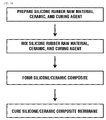
- FIG. 10 illustrates a method of forming a carbon dioxide separation membrane according to another embodiment of the present invention.
- the porous silicone membrane can be formed by mixing a silicone rubber raw material, ceramic powder and a curing agent, extruding the mixture, and curing the extruded mixture at a temperature of 80 to 300 °C.
- the method of forming a carbon dioxide separation membrane may include a) preparing a mixture by mixing a silicone rubber raw material, ceramic and a curing agent, b) stirring the mixture, c) extruding the stirred mixture as a ceramic-containing silicone composite membrane by injecting the stirred mixture into an extruder at a temperature of 50 to 100 °C, and d) curing the composite membrane at a temperature of 100 to 300 °C.
- the silicone rubber maintains its properties even at high temperature. Therefore, the silicon rubber exhibits far better tensile strength, elongation rate, and wear resistance than general organic rubber. Unlike other organic rubbers, the silicone rubber has a molecular structure without a double bond that creates cracks by reacting with oxygen, ozone, and ultraviolet rays in the atmosphere. Therefore, the silicone rubber has excellent weather resistance, which makes it hardly suffer from a change in physical properties even if used for a long period of time. In addition, the silicone rubber has heat resistance, low-temperature flexibility, excellent strength, and fire-retardant properties. Most of all, since the permeability of the silicone rubber to oxygen and organic vapor is high, the silicone rubber is used to concentrate oxygen in the air and collect organic vapor.
- the ceramic powder may be any one or more of Fe-based oxide, Pd-based oxide, Ti-base oxide, and Al-based oxide which have affinity for carbon dioxide.
- the ceramic powder may be any one or mixture of Fe 2 O 3 , TiO 2 , PdO, Al 2 O 3 , MgO, NiO, Y 2 O 3 , SiO 2 , ZrO 2 , and Zeolite.
- the ceramic powder may be used in an amount of 0.001 to 10 % by weight based on the weight of the silicone rubber raw material. Due to its superior affinity for carbon dioxide, the ceramic powder may facilitate the adsorption and diffusion of carbon dioxide to the separation membrane.
- the curing agent may be organic peroxide that can generate radicals through pyrolysis at a temperature of 20 to 200 °C.
- the curing agent may be, but is not limited to benzoyl peroxide, 2,4-dichlorobenzoyl peroxide, p-methylbenzoyl peroxide, O- methylbenzoyl peroxide, 2,4-dicumyl peroxide, 2,5-dimethyl-bis (2,5-t- butylperoxy) hexane, di-t-butyl peroxide, t-butyl perbenzoate, or 1,6-hexanediol-bis-t-butyl peroxy carbonate.
- the ceramic and the curing agent may be mixed with the silicone rubber raw material.
- the curing agent may be added in an amount of 0.1 to 15 parts by weight, in particular, 0.2 to 10 parts by weight based on 100 parts by weight of the total weight.
- the curing agent is added at less than 0.1 parts by weight, the rubber raw material may become too soft or a cheese state after being cured, thus making it inappropriate for use in the silicone separation membrane of the present invention.
- the curing agent is added at more than 15 parts by weight, mechanical/physical properties may be degraded, and it may take more time to remove the remaining curing agent after the curing process.
- the mixture of the ceramic and the curing agent may be mixed with the silicone rubber raw material and then stirred for 10 minutes to 5 hours at room temperature to mix them evenly.
- the mixture of the ceramic, the curing agent and the silicone rubber raw material is not stirred enough, it may cause a difference in the density of the ceramic in the silicone rubber raw material, make a thickness of the molded separation membrane non-uniform, and cause an exfoliation phenomenon. For this reason, the mixture of the ceramic, the curing agent and the silicone rubber raw material should be stirred enough.
- the stirred mixture of operation b) is extruded.
- the stirred mixture is injected into an extruder heated to a temperature of 50 to 100 °C and extruded as a ceramic-containing silicone composite membrane in the form of a tube.
- the ceramic-containing silicone composite membrane is cured up to an uncured portion in the heat of 100 to 300 °C at atmospheric pressure to produce a silicone ceramic composite membrane in the form of a tube.
- an increase in the content of the curing agent or an increase in curing temperature in the process of mixing the above raw materials can reduce the curing time.
- the use of a far-infrared panel heater can further reduce the time required to cure the silicone rubber.
- the silicone composite membrane obtained by extruding the stirred mixture may be molded into a vertical sheet, a horizontal sheet or a tube.
- the composite membrane obtained by extruding the stirred mixture may also be a porous silicone composite membrane that contains ceramic.
- the ceramic may has a grain size of 1 nm to 100 ⁇ m.
- a separation membrane made of porous silicone may be in the form of a tube having a diameter of 1 to 100 mm, more preferably, 2 to 50 mm.
- the separation membrane made of porous silicone may have a thickness of 0.05 to 3 mm, more preferably, 0.1 to 2 mm. When the diameter and thickness of the separation membrane is outside a predetermined range, the surface area and the permeability of carbon dioxide can be affected.
- pores formed in the silicone membrane may have a diameter of 0.3 to 0.37 nm, more preferably, 0.32 to 0.35 nm.
- silicone pores have a diameter of more than 0.38 nm based on a kinetic molecular diameter that is usually used to compare gas diffusivities, methane as well as carbon dioxide can be separated.
- silicon pores have a diameter of less than 0.33 nm, carbon dioxide may not be separated. Therefore, a porous silicone membrane having an appropriate pore diameter should be used.
- the nanoceramic powder used in the present invention may have an average grain size of 1 to 100 nm, more preferably, 2 to 50 nm.
- the ceramic-coated membrane in the present invention may have a thickness of 2 nm to 1000 ⁇ m.
- the ceramic-coated membrane is too thick or too thin, cracks or exfoliation can occur. Since carbon dioxide cannot permeate through a too thick ceramic-coated layer, the thickness of the ceramic-coated layer should be adjusted.
- the separation membrane may be coated with ceramic by dip coating, flow coating, roll coating or spray coating, preferably, by dip coating.
- the ceramic may be dispersed in water or any one of alcohol-based organic solvents such as methanol, ethanol and propanol and then used to coat the separation membrane.
- the ceramic may most preferably be dispersed in water.
- the ceramic may be dispersed for 30 minutes to 1 hour using an ultrasonic disperser and then be used to coat the separation membrane.
- the present invention may provide a method of separating carbon dioxide from a byproduct gas using an apparatus for separating carbon dioxide which includes a separator made of a porous silicone membrane.
- a difference in pressure between the inside and outside of the separator made of the porous silicone membrane is less than 4 kgf/cm 2 .
- the difference in pressure between the inside and outside of the separator is 4 kgf/cm 2 or greater, a flow rate of the byproduct gas increases, thus making it difficult for carbon dioxide to be absorbed and passed through the porous silicone membrane.
- the expansion of the porous silicone membrane may become noticeable. Therefore, it is desirable to separate carbon dioxide in the range of sound pressure near atmospheric pressure.
- carbon dioxide collected was qualitatively and quantitatively analyzed using gas chromatography analysis, and a flow rate was measured using a mass flow meter (MFC).
- MFC mass flow meter
- Example 1 Experiment conducted using a porous silicone tube as a separator.
- a porous silicone tube having a thickness of 2mm was installed as the porous silicone membrane 20 of FIG. 1 , and a mixed gas containing 50 % carbon dioxide and 50 % nitrogen was used as a byproduct gas.
- the byproduct gas was injected into a reactor at a constant flow rate of 2.5 cc/sec using the MFC.
- Example 2 Experiment conducted using a nanoceramic-coated porous silicone tube as a separation membrane.
- nanoceramic After 0.5 g of nanoceramic was mixed with 100 g of water, the mixture was dispersed sufficiently using an ultrasonic disperser. Then, a silicone tube having a thickness of 2 mm was immersed in the dispersed mixture for 30 minutes. After 30 minutes, the silicon tube was taken out from the dispersed mixture and dried for 3 to 4 hours at room temperature. This process was repeated three or more times so that the mixture can be evenly coated on the inside and outside of the tube.
- the coated porous silicone tube was installed as the porous silicone membrane 20 of FIG. 1 , and a mixed gas containing 50 % carbon dioxide and 50 % nitrogen was used as a byproduct gas.
- the byproduct gas was injected into a reactor at a constant flow rate of 2.5 cc/sec using the MFC.
- Example 1 of the present invention An experiment was conducted in the same way as in Example 1 of the present invention except that a porous silicone tube having a thickness of 0.5 mm was used as the porous silicone membrane 20 instead of the porous silicone tube having a thickness of 2 mm in Example 1.
- Example 1 of the present invention An experiment was conducted in the same way as in Example 1 of the present invention except that a porous silicone tube having a thickness of 0.1 mm was used as the porous silicone membrane 20 instead of the porous silicone tube having a thickness of 2 mm in Example 1.
- Example 2 of the present invention An experiment was conducted in the same way as in Example 2 of the present invention except that a porous silicone tube having a thickness of 0.5 mm instead of the porous silicone tube having a thickness of 2 mm in Example 2 was coated with nanoceramic and used as the porous silicone membrane 20.
- Example 2 of the present invention An experiment was conducted in the same way as in Example 2 of the present invention except that a porous silicone tube having a thickness of 0.1 mm instead of the porous silicone tube having a thickness of 2 mm in Example 2 was coated with nanoceramic and used as the porous silicone membrane 20.
- the collection rate of carbon dioxide is higher when a porous silicone membrane coated with a nanoceramic material is used as a separator according to the present invention than when a pure porous silicone separation membrane is used as the separator. This indicates that carbon dioxide can be separated more effectively in the present invention.
- Example 3 Example method of manufacturing a carbon dioxide separation membrane by mixing a silicone rubber raw material, ceramic powder and a curing agent and extruding the mixture.
- nanoceramic powder having a grain size of 20 nm to 50 ⁇ m is mixed with 10 g of benzoyl peroxide which is a curing agent.
- the mixture is stirred for 10 to 200 minutes at room temperature to evenly mix the nanoceramic powder and the curing agent.
- a separation membrane in the form of a sheet can be manufactured in the same way as the separation membrane in the form of a tube but may be extruded using an extrusion die in the shape of a sheet.
- the present invention uses a separator or plate made of a ceramic-coated porous silicone membrane. Therefore, the present invention can selectively separate carbon dioxide from a byproduct gas using a very small pressure difference and a simple method.
- the present invention can be applied to an apparatus for separating carbon dioxide from a waste gas.
- the apparatus since the apparatus is operated at room temperature by maintaining a difference in pressure between the inside and outside of a separation membrane at less than 4 kgf/cm 2 , energy consumption is low.
- the apparatus since the apparatus is simple, the product cost of the apparatus can be saved. Also, the apparatus can be installed even in dirty water that generates a byproduct gas or under water. Such ease of installation makes the apparatus industrially applicable.
Landscapes
- Chemical & Material Sciences (AREA)
- Chemical Kinetics & Catalysis (AREA)
- Engineering & Computer Science (AREA)
- Analytical Chemistry (AREA)
- General Chemical & Material Sciences (AREA)
- Oil, Petroleum & Natural Gas (AREA)
- Separation Using Semi-Permeable Membranes (AREA)
- Carbon And Carbon Compounds (AREA)
- Treating Waste Gases (AREA)
Applications Claiming Priority (3)
| Application Number | Priority Date | Filing Date | Title |
|---|---|---|---|
| KR1020130053058A KR101354680B1 (ko) | 2013-05-10 | 2013-05-10 | 실리콘 분리막을 이용한 이산화탄소 분리장치 |
| KR1020130119091A KR101522252B1 (ko) | 2013-10-07 | 2013-10-07 | 이산화탄소 분리막의 제조방법 및 이를 이용한 이산화탄소 분리장치 |
| PCT/KR2014/003757 WO2014181994A1 (ko) | 2013-05-10 | 2014-04-29 | 실리콘 분리막을 이용한 이산화탄소 분리장치 및 그 제조방법 |
Publications (2)
| Publication Number | Publication Date |
|---|---|
| EP2995366A1 true EP2995366A1 (de) | 2016-03-16 |
| EP2995366A4 EP2995366A4 (de) | 2017-05-17 |
Family
ID=51867431
Family Applications (1)
| Application Number | Title | Priority Date | Filing Date |
|---|---|---|---|
| EP14794902.8A Withdrawn EP2995366A4 (de) | 2013-05-10 | 2014-04-29 | Vorrichtung zur abscheidung von kohlendioxid unter verwendung einer silikontrennfolie und verfahren zur herstellung davon |
Country Status (11)
| Country | Link |
|---|---|
| US (1) | US9937464B2 (de) |
| EP (1) | EP2995366A4 (de) |
| JP (2) | JP2016519998A (de) |
| CN (1) | CN105209154A (de) |
| AU (1) | AU2014263432B2 (de) |
| BR (1) | BR112015027126A2 (de) |
| CA (2) | CA3003318C (de) |
| MX (1) | MX359580B (de) |
| RU (1) | RU2627370C2 (de) |
| SA (1) | SA515370116B1 (de) |
| WO (1) | WO2014181994A1 (de) |
Cited By (3)
| Publication number | Priority date | Publication date | Assignee | Title |
|---|---|---|---|---|
| US9937464B2 (en) | 2013-05-10 | 2018-04-10 | Arstroma Co., Ltd. | Device for separating carbon dioxide using silicone separation film and method for manufacturing same |
| EP3921403A4 (de) * | 2019-02-06 | 2022-10-19 | Aromaloc Inc. | Vorrichtung und verfahren zur konservierung des aromas eines fermentierbaren getränks |
| US11649421B2 (en) | 2013-04-18 | 2023-05-16 | Aromaloc Inc. | Apparatus and method for preserving the aroma of a fermentable beverage |
Families Citing this family (5)
| Publication number | Priority date | Publication date | Assignee | Title |
|---|---|---|---|---|
| US10711238B2 (en) | 2012-10-02 | 2020-07-14 | Repligen Corporation | Method for proliferation of cells within a bioreactor using a disposable pumphead and filter assembly |
| KR101540585B1 (ko) * | 2014-06-20 | 2015-07-31 | 한국과학기술연구원 | 기체회수장치 및 방법 |
| MX2017012181A (es) * | 2015-03-24 | 2018-01-24 | Arstroma Co Ltd | Aparato de separacion de fluido que comprende membrana de separacion de fluido y modulo de membrana de separacion de fluido. |
| US10464015B2 (en) * | 2016-05-19 | 2019-11-05 | Lawrence Livermore National Security, Llc | Molten hydroxide membrane for separation of acid gases from emissions |
| JP7148460B2 (ja) * | 2019-06-04 | 2022-10-05 | 本田技研工業株式会社 | Co2濃縮方法及びco2濃縮装置 |
Family Cites Families (42)
| Publication number | Priority date | Publication date | Assignee | Title |
|---|---|---|---|---|
| US4737165A (en) * | 1983-11-10 | 1988-04-12 | Uop Inc. | Multicomponent membranes |
| US4783202A (en) * | 1983-12-28 | 1988-11-08 | Kraus Menahem A | Polyphosphazene membrane separation of polar from non-polar fluids |
| JPH01194926A (ja) | 1988-01-26 | 1989-08-04 | Matsushita Electric Works Ltd | ガス分離システム |
| JPH03115027U (de) * | 1990-03-02 | 1991-11-27 | ||
| JPH0411692A (ja) | 1990-04-27 | 1992-01-16 | Nkk Corp | 高炉ガスの発熱量増加方法 |
| US5332547A (en) * | 1991-04-16 | 1994-07-26 | Prolong Systems, Inc. | Controlled atmosphere storage container |
| JPH0584861A (ja) * | 1991-09-30 | 1993-04-06 | Japan Gore Tex Inc | シリコーン樹脂を使用した複合材料 |
| GB2277885A (en) | 1992-10-31 | 1994-11-16 | Richard John Wakeman | Ceramic filter and membrane |
| JP3297542B2 (ja) * | 1994-08-31 | 2002-07-02 | 京セラ株式会社 | 積層無機分離体 |
| US5505824A (en) * | 1995-01-06 | 1996-04-09 | United Technologies Corporation | Propellant generator and method of generating propellants |
| JP3238873B2 (ja) | 1996-12-26 | 2001-12-17 | 財団法人石油産業活性化センター | 二酸化炭素の選択的分離膜および選択的分離方法 |
| JPH10249175A (ja) | 1997-03-12 | 1998-09-22 | Kyocera Corp | 多孔質分離膜及びその製造方法 |
| JP3938223B2 (ja) | 1997-06-09 | 2007-06-27 | 三菱化工機株式会社 | 消化ガス利用燃料電池設備 |
| JP3501951B2 (ja) | 1998-06-24 | 2004-03-02 | 財団法人電力中央研究所 | 二酸化炭素分離膜 |
| JP3559470B2 (ja) | 1999-03-31 | 2004-09-02 | 京セラ株式会社 | ガス分離フィルタおよびその製造方法 |
| US6368382B1 (en) * | 2000-07-27 | 2002-04-09 | Uop Llc | Epoxysilicone coated membranes |
| US20020056371A1 (en) | 2000-09-27 | 2002-05-16 | Hawkeye Enterprises, Llc | Membrane system and method for separation of gases |
| JP4711544B2 (ja) | 2001-05-29 | 2011-06-29 | 京セラ株式会社 | 流体分離セル及び流体分離装置 |
| JP2004141809A (ja) * | 2002-10-25 | 2004-05-20 | Kyocera Corp | 流体分離フィルタ及び流体分離モジュール |
| US6938439B2 (en) * | 2003-05-22 | 2005-09-06 | Cool Clean Technologies, Inc. | System for use of land fills and recyclable materials |
| US7179325B2 (en) * | 2004-02-10 | 2007-02-20 | Virginia Tech Intellectual Properties, Inc. | Hydrogen-selective silica-based membrane |
| JP2006266108A (ja) * | 2005-03-22 | 2006-10-05 | Denso Corp | 排気温度制御装置 |
| US7604690B2 (en) * | 2005-04-05 | 2009-10-20 | Wostec, Inc. | Composite material for ultra thin membranes |
| US7344585B1 (en) | 2005-08-31 | 2008-03-18 | Uop Llc | Mixed matrix membrane for gas separation |
| WO2007116908A1 (ja) * | 2006-04-04 | 2007-10-18 | Taiyo Nippon Sanso Corporation | メタン分離方法、メタン分離装置及びメタン利用システム |
| KR100734926B1 (ko) | 2006-06-30 | 2007-07-03 | 이인화 | 액상 철 킬레이트 촉매를 이용한 황화합물 제거 및 메탄과이산화탄소 분리장치 |
| JP5324067B2 (ja) * | 2006-08-22 | 2013-10-23 | 日本碍子株式会社 | ゼオライト膜の製造方法 |
| PT2099921E (pt) * | 2006-12-11 | 2011-06-01 | Ralf Salvetzki | Processo para produção biológica de metano |
| US7811359B2 (en) | 2007-01-18 | 2010-10-12 | General Electric Company | Composite membrane for separation of carbon dioxide |
| BRPI0817328A2 (pt) * | 2007-09-25 | 2015-03-24 | Kubota Kk | Método e aparelho para tratamento de resíduo orgânico. |
| DE102007058548B4 (de) * | 2007-12-05 | 2009-10-15 | Landwärme GbR (vertretungsberechtigter Gesellschafter, Tobias Assmann, 80638 München) | Verfahren zum Aufreinigen von Biogas |
| US7938894B2 (en) * | 2008-02-14 | 2011-05-10 | Conocophillips Company | Hybrid organic-inorganic gas separation membranes |
| DE102009047351A1 (de) * | 2009-12-01 | 2011-06-09 | Evonik Goldschmidt Gmbh | Komposit-Siliconmembranen mit hoher Trennwirkung |
| US8158378B2 (en) * | 2010-02-03 | 2012-04-17 | Guild Associates, Inc. | Utilizing waste tail gas from a separation unit biogas upgrade systems as beneficial fuel |
| JP5799094B2 (ja) | 2010-07-09 | 2015-10-21 | エコ テクノル プロプライエタリー リミテッド | 膜技術の使用によるシンガスの生成 |
| KR101059830B1 (ko) | 2011-04-04 | 2011-08-29 | 주식회사 코아 에프앤티 | 환경기초시설에서 발생되어 메탄과 이산화탄소를 다량 함유한 부생가스의 유용성분 회수 방법 및 그 시스템 |
| WO2012138755A1 (en) * | 2011-04-08 | 2012-10-11 | Dongchan Ahn | Method of preparing gas selective membrane using epoxy-functional siloxanes |
| WO2012170541A1 (en) | 2011-06-06 | 2012-12-13 | Dongchan Ahn | Membrane derived from polyether- and siliceous filler-containing silicone composition |
| WO2014080670A1 (ja) * | 2012-11-21 | 2014-05-30 | 東洋ゴム工業株式会社 | 酸性ガス含有ガス処理用分離膜及びその製造方法、酸性ガス又はメタンガスの分離方法、並びに酸性ガス又はメタンガスの製造方法 |
| CA3003318C (en) | 2013-05-10 | 2019-03-12 | Arstroma Co., Ltd. | Device for separating carbon dioxide using silicone separation film and method for manufacturing the same |
| US10787615B2 (en) * | 2014-01-28 | 2020-09-29 | Praxair Technology, Inc. | Method and system for treating a flow back fluid exiting a well site |
| EP2965800B1 (de) * | 2014-07-08 | 2019-01-30 | Airbus Defence and Space GmbH | Verfahren und Vorrichtung zu einer Gasaufbereitung |
-
2014
- 2014-04-29 CA CA3003318A patent/CA3003318C/en not_active Expired - Fee Related
- 2014-04-29 BR BR112015027126A patent/BR112015027126A2/pt not_active Application Discontinuation
- 2014-04-29 US US14/785,445 patent/US9937464B2/en active Active
- 2014-04-29 EP EP14794902.8A patent/EP2995366A4/de not_active Withdrawn
- 2014-04-29 MX MX2015015181A patent/MX359580B/es active IP Right Grant
- 2014-04-29 RU RU2015152510A patent/RU2627370C2/ru active
- 2014-04-29 AU AU2014263432A patent/AU2014263432B2/en not_active Ceased
- 2014-04-29 CN CN201480026648.4A patent/CN105209154A/zh active Pending
- 2014-04-29 WO PCT/KR2014/003757 patent/WO2014181994A1/ko not_active Ceased
- 2014-04-29 CA CA2909395A patent/CA2909395C/en not_active Expired - Fee Related
- 2014-04-29 JP JP2016512821A patent/JP2016519998A/ja active Pending
-
2015
- 2015-11-08 SA SA515370116A patent/SA515370116B1/ar unknown
-
2017
- 2017-11-07 JP JP2017215000A patent/JP2018047463A/ja active Pending
Cited By (4)
| Publication number | Priority date | Publication date | Assignee | Title |
|---|---|---|---|---|
| US11649421B2 (en) | 2013-04-18 | 2023-05-16 | Aromaloc Inc. | Apparatus and method for preserving the aroma of a fermentable beverage |
| US9937464B2 (en) | 2013-05-10 | 2018-04-10 | Arstroma Co., Ltd. | Device for separating carbon dioxide using silicone separation film and method for manufacturing same |
| EP3921403A4 (de) * | 2019-02-06 | 2022-10-19 | Aromaloc Inc. | Vorrichtung und verfahren zur konservierung des aromas eines fermentierbaren getränks |
| AU2020218378B2 (en) * | 2019-02-06 | 2025-08-28 | Aromaloc Inc. | Apparatus and method for preserving the aroma of a fermentable beverage |
Also Published As
| Publication number | Publication date |
|---|---|
| CN105209154A (zh) | 2015-12-30 |
| EP2995366A4 (de) | 2017-05-17 |
| JP2016519998A (ja) | 2016-07-11 |
| CA3003318C (en) | 2019-03-12 |
| CA2909395A1 (en) | 2014-11-13 |
| CA3003318A1 (en) | 2014-11-13 |
| SA515370116B1 (ar) | 2016-05-01 |
| MX2015015181A (es) | 2016-06-02 |
| US9937464B2 (en) | 2018-04-10 |
| RU2015152510A (ru) | 2017-06-16 |
| MX359580B (es) | 2018-10-03 |
| US20160059181A1 (en) | 2016-03-03 |
| AU2014263432A1 (en) | 2015-11-12 |
| WO2014181994A1 (ko) | 2014-11-13 |
| JP2018047463A (ja) | 2018-03-29 |
| AU2014263432B2 (en) | 2017-02-02 |
| RU2627370C2 (ru) | 2017-08-08 |
| CA2909395C (en) | 2018-11-06 |
| BR112015027126A2 (pt) | 2018-04-24 |
Similar Documents
| Publication | Publication Date | Title |
|---|---|---|
| US9937464B2 (en) | Device for separating carbon dioxide using silicone separation film and method for manufacturing same | |
| KR101354680B1 (ko) | 실리콘 분리막을 이용한 이산화탄소 분리장치 | |
| Moral et al. | Hydrogen recovery from coke oven gas. Comparative analysis of technical alternatives | |
| Liu et al. | CO2/N2 separation by poly (ether block amide) thin film hollow fiber composite membranes | |
| Murali et al. | Gas permeation behavior of Pebax-1657 nanocomposite membrane incorporated with multiwalled carbon nanotubes | |
| US4685940A (en) | Separation device | |
| US8900435B2 (en) | Separating gas using ion exchange | |
| Rahimalimamaghani et al. | Carbon molecular sieve membranes for selective CO2/CH4 and CO2/N2 separation: Experimental study, optimal process design, and economic analysis | |
| EP2716347A1 (de) | Zeolithmembranentrennung und -rückgewinnung für co2 | |
| JP2019520198A (ja) | ガス分離のためのプロセスおよび機器 | |
| JP5124158B2 (ja) | メタン濃縮装置およびメタン濃縮方法 | |
| CN104220645A (zh) | 制造高纯度一氧化碳的装置 | |
| Hong et al. | Improvement of hydrogen-separating performance by on-stream catalytic cracking of silane over hollow fiber MFI zeolite membrane | |
| KR20200113517A (ko) | 메탄 선택적 작용기가 도입된 유무기 복합 다공체를 포함하는 메탄 선택성 복합 분리막, 이의 용도 및 이의 제조방법 | |
| JP2013049008A (ja) | 酸素富化空気を製造するシステムおよび方法 | |
| WO2024014493A1 (ja) | ガス分離システム及びメタン富化ガスの製造方法 | |
| EP3267524B1 (de) | Brennstoffzellensystem | |
| EP1647531B1 (de) | Methode zum Konzentrieren von Methan aus Klärschlamm und Methanlagerungsausstattung | |
| JP2014000535A (ja) | 二酸化炭素の分離方法及び二酸化炭素の分離膜 | |
| JP2007021472A (ja) | 酸素水製造方法及びその装置 | |
| US20250197750A1 (en) | Liquid fuel production system and liquid fuel production method | |
| KR101522252B1 (ko) | 이산화탄소 분리막의 제조방법 및 이를 이용한 이산화탄소 분리장치 | |
| Rosiah et al. | Purification of biohydrogen produced from palm oil mill effluent fermentation for fuel cell application | |
| Yildirim et al. | An experimental study of CO2 separation using a silica based composite membrane | |
| JP2007260630A (ja) | 水素分離ユニット |
Legal Events
| Date | Code | Title | Description |
|---|---|---|---|
| PUAI | Public reference made under article 153(3) epc to a published international application that has entered the european phase |
Free format text: ORIGINAL CODE: 0009012 |
|
| 17P | Request for examination filed |
Effective date: 20151109 |
|
| AK | Designated contracting states |
Kind code of ref document: A1 Designated state(s): AL AT BE BG CH CY CZ DE DK EE ES FI FR GB GR HR HU IE IS IT LI LT LU LV MC MK MT NL NO PL PT RO RS SE SI SK SM TR |
|
| AX | Request for extension of the european patent |
Extension state: BA ME |
|
| RAP1 | Party data changed (applicant data changed or rights of an application transferred) |
Owner name: ARSTROMA CO., LTD. |
|
| RIN1 | Information on inventor provided before grant (corrected) |
Inventor name: KIM, GWAN SHIG Inventor name: SHIN, KI YEONG |
|
| DAX | Request for extension of the european patent (deleted) | ||
| RIC1 | Information provided on ipc code assigned before grant |
Ipc: B01D 53/22 20060101AFI20161206BHEP |
|
| RIC1 | Information provided on ipc code assigned before grant |
Ipc: B01D 53/22 20060101AFI20170328BHEP |
|
| A4 | Supplementary search report drawn up and despatched |
Effective date: 20170413 |
|
| RIC1 | Information provided on ipc code assigned before grant |
Ipc: B01D 53/22 20060101AFI20170408BHEP |
|
| STAA | Information on the status of an ep patent application or granted ep patent |
Free format text: STATUS: EXAMINATION IS IN PROGRESS |
|
| 17Q | First examination report despatched |
Effective date: 20190328 |
|
| STAA | Information on the status of an ep patent application or granted ep patent |
Free format text: STATUS: THE APPLICATION IS DEEMED TO BE WITHDRAWN |
|
| 18D | Application deemed to be withdrawn |
Effective date: 20190808 |