EP2995368B1 - Procédé de fabrication de nanotrous et filtre fabriqué par ce dernier - Google Patents
Procédé de fabrication de nanotrous et filtre fabriqué par ce dernier Download PDFInfo
- Publication number
- EP2995368B1 EP2995368B1 EP15153186.0A EP15153186A EP2995368B1 EP 2995368 B1 EP2995368 B1 EP 2995368B1 EP 15153186 A EP15153186 A EP 15153186A EP 2995368 B1 EP2995368 B1 EP 2995368B1
- Authority
- EP
- European Patent Office
- Prior art keywords
- particles
- hole
- nanoholes
- outlet
- diameter
- Prior art date
- Legal status (The legal status is an assumption and is not a legal conclusion. Google has not performed a legal analysis and makes no representation as to the accuracy of the status listed.)
- Active
Links
Images




Classifications
-
- B—PERFORMING OPERATIONS; TRANSPORTING
- B01—PHYSICAL OR CHEMICAL PROCESSES OR APPARATUS IN GENERAL
- B01D—SEPARATION
- B01D71/00—Semi-permeable membranes for separation processes or apparatus characterised by the material; Manufacturing processes specially adapted therefor
- B01D71/02—Inorganic material
- B01D71/024—Oxides
- B01D71/025—Aluminium oxide
-
- B—PERFORMING OPERATIONS; TRANSPORTING
- B01—PHYSICAL OR CHEMICAL PROCESSES OR APPARATUS IN GENERAL
- B01D—SEPARATION
- B01D69/00—Semi-permeable membranes for separation processes or apparatus characterised by their form, structure or properties; Manufacturing processes specially adapted therefor
-
- B—PERFORMING OPERATIONS; TRANSPORTING
- B01—PHYSICAL OR CHEMICAL PROCESSES OR APPARATUS IN GENERAL
- B01D—SEPARATION
- B01D67/00—Processes specially adapted for manufacturing semi-permeable membranes for separation processes or apparatus
- B01D67/0081—After-treatment of organic or inorganic membranes
- B01D67/0088—Physical treatment with compounds, e.g. swelling, coating or impregnation
-
- C—CHEMISTRY; METALLURGY
- C01—INORGANIC CHEMISTRY
- C01B—NON-METALLIC ELEMENTS; COMPOUNDS THEREOF; METALLOIDS OR COMPOUNDS THEREOF NOT COVERED BY SUBCLASS C01C
- C01B32/00—Carbon; Compounds thereof
-
- C—CHEMISTRY; METALLURGY
- C25—ELECTROLYTIC OR ELECTROPHORETIC PROCESSES; APPARATUS THEREFOR
- C25D—PROCESSES FOR THE ELECTROLYTIC OR ELECTROPHORETIC PRODUCTION OF COATINGS; ELECTROFORMING; APPARATUS THEREFOR
- C25D11/00—Electrolytic coating by surface reaction, i.e. forming conversion layers
- C25D11/02—Anodisation
- C25D11/04—Anodisation of aluminium or alloys based thereon
- C25D11/045—Anodisation of aluminium or alloys based thereon for forming AAO templates
-
- C—CHEMISTRY; METALLURGY
- C25—ELECTROLYTIC OR ELECTROPHORETIC PROCESSES; APPARATUS THEREFOR
- C25D—PROCESSES FOR THE ELECTROLYTIC OR ELECTROPHORETIC PRODUCTION OF COATINGS; ELECTROFORMING; APPARATUS THEREFOR
- C25D11/00—Electrolytic coating by surface reaction, i.e. forming conversion layers
- C25D11/02—Anodisation
- C25D11/04—Anodisation of aluminium or alloys based thereon
- C25D11/18—After-treatment, e.g. pore-sealing
-
- B—PERFORMING OPERATIONS; TRANSPORTING
- B01—PHYSICAL OR CHEMICAL PROCESSES OR APPARATUS IN GENERAL
- B01D—SEPARATION
- B01D2323/00—Details relating to membrane preparation
- B01D2323/28—Pore treatments
- B01D2323/283—Reducing the pores
-
- B—PERFORMING OPERATIONS; TRANSPORTING
- B01—PHYSICAL OR CHEMICAL PROCESSES OR APPARATUS IN GENERAL
- B01D—SEPARATION
- B01D67/00—Processes specially adapted for manufacturing semi-permeable membranes for separation processes or apparatus
- B01D67/0039—Inorganic membrane manufacture
- B01D67/0053—Inorganic membrane manufacture by inducing porosity into non porous precursor membranes
- B01D67/006—Inorganic membrane manufacture by inducing porosity into non porous precursor membranes by elimination of segments of the precursor, e.g. nucleation-track membranes, lithography or laser methods
- B01D67/0065—Inorganic membrane manufacture by inducing porosity into non porous precursor membranes by elimination of segments of the precursor, e.g. nucleation-track membranes, lithography or laser methods by anodic oxidation
Definitions
- the present invention relates to a method for manufacturing nanoholes and a filter manufactured by the same, and more particularly, to a method for manufacturing nanoholes, the method being capable of easily manufacturing nanoholes with a size of several to hundreds of nanometers, and to a filter manufactured by the same.
- a nanohole refers to a pore or passage having a nanoscale width, and is used in various fields, such as for a computing device and a memory device.
- the shape limit of a photosensitive film is at least 1 ⁇ m due to optical diffraction of a photo-mask. Therefore, it is, in fact, difficult to realize several nanometer-sized nanoholes through the above techniques.
- the present invention has been made in an effort to provide a method for manufacturing nanoholes and a filter manufactured by the same, having advantages of easily and simply manufacturing nanoholes with a scale of several nanometers or less.
- the present invention provides a method for manufacturing nanoholes as defined in claim 1.
- a plurality of kinds of particles with different sizes may be injected into the through-hole.
- the same kind of particles with the same size may be injected into the through-hole.
- the present invention provides a filter as defined in claim 5.
- the size of the nanoholes may be controlled by adjusting the size of particles injected into the through-hole.
- the particles may have electrically positive or negative polarity by binding to a functional group.
- FIG. 1 is a process flowchart schematically showing a method for manufacturing nanoholes according a first embodiment of the present invention.
- the method S100 for manufacturing nanoholes according to the first embodiment of the present invention, particles with a smaller size than a nano- or micro-scale through-hole 11 are injected into the through-hole 11, and as a result, nanoholes 30 with a size of several nanometers or smaller can be manufactured, wherein the method comprises a preparing step S110 and a particle injecting step S120.
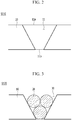
- FIG. 2 is a front view schematically illustrating a preparing step in the method for manufacturing nanoholes shown in FIG. 1 .
- a body 10 which passes through two facing surfaces and has a through-hole 11 with a nano- or micro-scale diameter is prepared.
- the through-hole 11 is formed to pass through upper and lower surfaces of the body 10, or right and left surfaces of the body 10.
- the through-hole 11 is prepared such that, based on a direction in which particles 20 are injected in the below-described particle injecting step S120, an inlet 11a, through which the particles 20 are injected, and an outlet 11b, which is opposite to the inlet 11a, are asymmetric.
- the shape of the inlet 11a and the shape of the outlet 11b may be asymmetric to each other by differently preparing the diameter of the inlet 11a and the diameter of the outlet 11b.
- the diameter of the inlet 11a is prepared to be larger than the diameter of the outlet 11b, thereby preventing the particles 20 injected in the particle injecting step S120 from leaving through the outlet 11b.
- the diameter of the outlet 11b is smaller than the diameter of the particles 20 injected in the below-described particle injecting step S120, but is not limited thereto.
- particles with a smaller diameter than the through-hole 11 are injected into the through-hole 11, thereby manufacturing nanoholes with a smaller scale than the through-hole 11.
- the particles 20 are injected into the through-hole 11, and thus nanoholes 30 are formed by pores formed between the particles 20.
- nanoholes 30 with a user-desired size can be manufactured by selecting the kind of injected particles 20.
- FIG. 3 is a view illustrating a state in which particles with the same size are injected in the particle injecting step in the method for manufacturing nanoholes shown in FIG. 1
- FIG. 4 is a view illustrating a state in which particles with different sizes are injected in the particle injecting step in the method for manufacturing nanoholes shown in FIG. 1 .
- nanoholes 30 having a constant size that is smaller than the diameter of the injected particles 20 can be manufactured.
- nanoholes 30 with a user-desired size can be manufactured by selecting the size of injected particles 20
- the particles injected in the particle injecting step S120 may be a plurality of kinds of particles with different sizes.
- first particles 21 and second particles 22 having a smaller diameter than the first particles 21 may be simultaneously or sequentially injected into the through-hole 11.
- the second particles 22 are disposed in pores formed in a state in which the first particles 21 are arranged, and thus nanoholes 30 with a more minute scale can be formed when compared with the case in which only the first particles are injected.
- the present embodiment exemplifies the provision of two kinds of particles, that is, the first particles 21 and the second particles 22 having different sizes, but it is not limited thereto, and thus more minute nanoholes 30 can be manufactured by using two or more kinds of particles.
- the nanoholes 30 formed in the first embodiment of the present invention may have a pico-scale size.
- the particles injected in the particle injecting step S120 may be electrically or chemically treated particles. That is, particles that are surface-functionalized by an electrical or chemical treatment may be injected into the through-hole 11.
- the surfaces of the particles 20 may be positively charged using a peptide. That is, the peptide may bind to the surfaces of the particles 20 by providing a functional group, such as a hydroxyl group (OH) or a carboxyl group (COOH), to the surfaces of the particles 20.
- a functional group such as a hydroxyl group (OH) or a carboxyl group (COOH)
- FIG. 5 is a view schematically showing the binding of a functional group to a particle surface in the particle injecting step in the method for manufacturing nanoholes shown in FIG. 1 .
- Such a peptide has electrically positive (+) polarity since hydrogen is separated from a functional group, such as a hydroxyl group (OH) or a carboxyl group (COOH), and thus can limit the kind of particles which can pass through nanoholes 30.
- a functional group such as a hydroxyl group (OH) or a carboxyl group (COOH)
- the particles 20 may be injected into the through-hole 11 while the particles are charged, so that an electrically charged electric double layer is formed on surfaces of the particles.
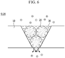
- FIG. 6 is a view schematically showing a state in which an electric double layer is formed by injecting charged particles in the particle injecting step in the method for manufacturing nanoholes shown in FIG. 1 .
- the term electric double layer refers to a phenomenon in which charges are naturally formed along the particle, and a phenomenon in which charges having opposite polarity to charges formed on the particle form a layer around the charge.
- a layer having negative (-) polarity is formed around the particle 20.
- electrically negative (-) particles have limitations in passing through the nanohole 30, and only electrically positive (+) or neutral particles can pass through the nanohole 30.
- the particles 20 are surface-functionalized through an electric or chemical treatment, but is not limited thereto, and thus the conventionally known various methods can be utilized.
- FIG. 7 is a process flowchart schematically showing a method for manufacturing nanoholes according a second embodiment of the present invention.
- the method S200 for manufacturing nanoholes according to the second embodiment of the present invention, particles with a smaller size than a nano- or micro-scale through-hole 11 are injected into the through-hole 11, and as a result, nanoholes 30 with a size of several nanometers or smaller can be manufactured, wherein the method includes a preparing step S110, an inlet reducing step S215, and a particle injecting step S120.
- the present embodiment is different from the first embodiment in that a body 10 including a through-hole 11 of which an inlet 11a and an outlet 11b are symmetric to each other is utilized.
- the body 10 of the second embodiment includes the through-hole 11 having a structure in which the shape of the inlet 11a and the shape of the outlet 11b correspond to each other by forming the inlet 11a and the outlet 11b to have the same diameter.
- the through-hole 11 may be formed such that the diameter of the inlet 11a and the diameter of the outlet 11b are the same, and more preferably, the center of the inlet 11a and the center of the outlet 11b are on the same central axis.
- particles 20 injected in the below-describing particle injecting step (S120) can naturally leave through the outlet 11b.
- FIG. 8 is a view schematically illustrating an outlet reduction step in the method for manufacturing nanoholes shown in FIG. 7 .
- an outlet reducing member 12 for shielding a part of the outlet 11b is provided on a surface of the body in which the outlet 11b is formed, in order to prevent the particles from leaving through the outlet 11b.
- the outlet reducing member 12 having a penetration hole formed on an external surface thereof is attached to the surface of the body 10 in which the outlet 11b is formed.
- the size of the penetration hole of the outlet reducing member 12 may be similar to or smaller than that of the outlet 11b. That is, the outlet reducing member 12 is attached to the surface of the body 10 in which the outlet 11b is formed, thereby shielding a part of the outlet 11b. Therefore, the outlet reducing member 12 prevents the particles 20 from passing through the outlet 11b and leaving the through-hole 11.
- the size of the outlet 11b can be reduced by disposing the penetration hole of the outlet reducing member 12 and the outlet 11b to be oblique to each other, that is, partially overlapping the outlet 11b and a region of the outlet reducing member 12 in which the penetration hole is not formed.
- the outlet reducing step S215 according to the second embodiment of the present invention may be performed as long as a predetermined material is bonded on the edge of the outlet 11b or the size of the outlet 11b is reduced by any other method.
- FIG. 9 is a view schematically showing a filter according to an embodiment of the present invention.
- FIG. 10 is an image showing an enlarged external surface of anodic aluminum oxide used as a filter part of the filter shown in FIG. 9 .
- a filter 300 according to an embodiment of the present invention has nanoholes manufactured by the method for manufacturing nanoholes according to the above-described first or second embodiment, and includes a filter part 310 and particles 320.
- the filter part 310 has a plurality of through-holes 311 passing through external surfaces thereof, contaminants are filtered by the through-holes 311, and thus purified air can be exhausted.
- the through-holes 311 have a scale of tens to hundreds of nanometers, and can filter minute particles with a larger scale than the through-holes 311.
- the filter part 310 may be prepared by an anodic aluminum oxidation filter.
- an inlet 311a and an outlet 311b of the through-hole 311 are asymmetric, and thus even though particles 320 are injected through the inlet 311a, the particles 320 do not leave through the outlet 311b due to the structural characteristics of the through-hole 311.
- a through-hole 311 having a symmetric structure as described in the methods (S100 and S200) for manufacturing nanoholes according to the first and second embodiments may be used.
- the particles 320 are inserted into the through-hole 311 to reduce the scale of the through-hole 311 to the several nano-scales or pico-scales. As described in the methods S100 and S200 for manufacturing nanoholes according to the first and second embodiments, a part of the through-hole 311 is shielded by the particles 310 placed inside the through-hole 311, and thus nanoholes 330 having a smaller scale than the through-hole 311 are manufactured.
- the particles may be placed inside the through-hole 311 while being surface-functionalized, and this feature is substantially the same as those in the methods S100 and S200 for manufacturing nanoholes according to the first and second embodiments, and thus a detailed description thereof will be omitted.
- the particles 320 have electrically positive (+) or negative (-) polarity by an electrical or chemical treatment, and thus the filter part 310 can selectively pass through only predetermined materials in air.
Landscapes
- Chemical & Material Sciences (AREA)
- Chemical Kinetics & Catalysis (AREA)
- Organic Chemistry (AREA)
- Inorganic Chemistry (AREA)
- Engineering & Computer Science (AREA)
- Electrochemistry (AREA)
- Materials Engineering (AREA)
- Metallurgy (AREA)
- Manufacturing & Machinery (AREA)
- Filtering Materials (AREA)
- Physical Or Chemical Processes And Apparatus (AREA)
Claims (7)
- Procédé de fabrication de nano-trous (30), le procédé comprenant :une étape de préparation consistant à préparer un corps (10) ayant un trou traversant (11) qui traverse deux surfaces en regard et a un diamètre nanométrique, le corps (10) étant une membrane d'oxyde d'aluminium anodique (AAO) ; etune étape d'injection de particules consistant à injecter des particules (20) dans le trou traversant (11) à travers une entrée (11a) du trou traversant (11) pour former des nano-trous (30) ayant une taille inférieure au trou traversant (11),dans lequel l'entrée (11a) et une sortie (11b) opposée à l'entrée (11a), sont formées dans une structure asymétrique,dans lequel, dans le trou traversant (11), le diamètre de l'entrée (11a) est supérieur à celui de la sortie (11b), le diamètre de l'entrée (11a) est supérieur au diamètre des particules (20) et le diamètre de la sortie (11b) est inférieur au diamètre des particules (20), de sorte que les particules (20) injectées dans l'étape d'injection de particules ne quittent pas le trou traversant (11) par la sortie (11b),dans lequel, dans l'étape d'injection de particules, les nano-trous (30) sont formés par des pores entre les particules (20), caractérisé en ce queune surface des particules (20) est chargée positivement ou négativement de sorte qu'une double couche électrique chargée électriquement soit formée sur la surface de la particule (20) ou une région adjacente à la surface.
- Procédé de la revendication 1, dans lequel dans l'étape d'injection de particules, une pluralité de types de particules (20) ayant des tailles différentes sont injectés dans le trou traversant (11).
- Procédé de la revendication 1, dans lequel dans l'étape d'injection de particules, le même type de particules (20) ayant la même taille est injecté dans le trou traversant (11).
- Procédé de la revendication 1, dans lequel dans l'étape d'injection de particules, les particules ont une polarité électriquement positive ou négative par un traitement électrique ou chimique.
- Filtre comprenant :une partie de filtre ayant un trou traversant (11) qui pénètre deux surfaces en regard et a un diamètre nanométrique ; etdes particules (20) injectées dans le trou traversant (11) à travers une entrée (11a) du trou traversant (11),dans lequel, l'entrée (11a) et une sortie (11b) opposée à l'entrée (11a), sont formées dans une structure asymétrique,dans lequel, dans le trou traversant (11), le diamètre de l'entrée (11a) est supérieur à celui d'une sortie (11b), qui est opposée à l'entrée (11a), le diamètre de l'entrée (11a) est supérieur au diamètre des particules (20) et le diamètre de la sortie (11b) est inférieur au diamètre des particules (20), de sorte que les particules (20) injectées dans le trou traversant (11) ne quittent pas le trou traversant (11) par la sortie (11b),dans lequel, la partie de filtre est une membrane d'oxyde d'aluminium anodique (AAO),dans lequel, la partie de filtre a des nano-trous (30), ayant une taille inférieure à celle du trou traversant (11), lorsque les particules (20) sont injectées dans le trou traversant (11),dans lequel, les nano-trous (30) sont des pores entre les particules (20), caractérisés en ce queune surface des particules (20) est chargée positivement ou négativement de sorte qu'une double couche électrique chargée électriquement soit formée sur la surface de la particule (20) ou une région adjacente à la surface.
- Filtre de la revendication 5, dans lequel la taille des nano-trous (30) est contrôlée en régulant la taille de particules (20) injectées dans le trou traversant (11).
- Filtre de la revendication 5, dans lequel les particules (20) ont une polarité électriquement positive ou négative en se liant à un groupe fonctionnel.
Applications Claiming Priority (1)
| Application Number | Priority Date | Filing Date | Title |
|---|---|---|---|
| KR1020140121300A KR101605632B1 (ko) | 2014-09-12 | 2014-09-12 | 나노 홀의 제조방법 및 이에 의해 제조된 필터 |
Publications (2)
| Publication Number | Publication Date |
|---|---|
| EP2995368A1 EP2995368A1 (fr) | 2016-03-16 |
| EP2995368B1 true EP2995368B1 (fr) | 2020-08-19 |
Family
ID=52432720
Family Applications (1)
| Application Number | Title | Priority Date | Filing Date |
|---|---|---|---|
| EP15153186.0A Active EP2995368B1 (fr) | 2014-09-12 | 2015-01-30 | Procédé de fabrication de nanotrous et filtre fabriqué par ce dernier |
Country Status (3)
| Country | Link |
|---|---|
| EP (1) | EP2995368B1 (fr) |
| KR (1) | KR101605632B1 (fr) |
| SG (1) | SG10201500789XA (fr) |
Families Citing this family (11)
| Publication number | Priority date | Publication date | Assignee | Title |
|---|---|---|---|---|
| US10980919B2 (en) | 2016-04-14 | 2021-04-20 | Lockheed Martin Corporation | Methods for in vivo and in vitro use of graphene and other two-dimensional materials |
| US10653824B2 (en) | 2012-05-25 | 2020-05-19 | Lockheed Martin Corporation | Two-dimensional materials and uses thereof |
| US9572918B2 (en) | 2013-06-21 | 2017-02-21 | Lockheed Martin Corporation | Graphene-based filter for isolating a substance from blood |
| EP3099645A4 (fr) | 2014-01-31 | 2017-09-27 | Lockheed Martin Corporation | Procédés de formation de structures composites avec un matériau à deux dimensions à l'aide d'une couche de support non-sacrificielle poreuse |
| EP3331588A4 (fr) * | 2015-08-05 | 2019-04-03 | Lockheed Martin Corporation | Matériaux bi-dimensionnels et leurs utilisations |
| AU2016303048A1 (en) | 2015-08-05 | 2018-03-01 | Lockheed Martin Corporation | Perforatable sheets of graphene-based material |
| WO2017023380A1 (fr) | 2015-08-05 | 2017-02-09 | Lockheed Martin Corporation | Matériaux bi-dimensionnels et leurs utilisations |
| MX2018001559A (es) | 2015-08-06 | 2018-09-27 | Lockheed Corp | Modificacion de nanoparticula y perforacion de grafeno. |
| EP3442697A4 (fr) | 2016-04-14 | 2020-03-18 | Lockheed Martin Corporation | Atténuation interfaciale sélective des défauts du graphène |
| KR101930068B1 (ko) | 2017-04-03 | 2018-12-17 | 한국기계연구원 | 표적 입자 검출용 멤브레인 필터, 이의 제조방법 및 이를 이용한 표적 입자 검출 방법 |
| KR101980244B1 (ko) * | 2017-11-15 | 2019-08-28 | 한국기계연구원 | 상분리용 옴니 멤브레인 및 그 제작 방법 |
Family Cites Families (10)
| Publication number | Priority date | Publication date | Assignee | Title |
|---|---|---|---|---|
| NL126633C (fr) * | 1958-02-24 | 1900-01-01 | ||
| JPS6414875A (en) * | 1987-07-08 | 1989-01-19 | Yamaha Motor Co Ltd | Separator for fuel cell |
| US6613241B1 (en) * | 1999-10-29 | 2003-09-02 | California Insitute Of Technology | MEMS elements with integrated porous membranes and method of making the same |
| JP2005144363A (ja) * | 2003-11-17 | 2005-06-09 | Nissan Motor Co Ltd | 水素分離膜構造体およびその製造方法 |
| US7669719B2 (en) * | 2006-07-05 | 2010-03-02 | General Electric Company | Membrane structure and method of making |
| JP2008027676A (ja) * | 2006-07-19 | 2008-02-07 | Tokai Rubber Ind Ltd | 異方性導電膜の製造方法および異方性導電膜 |
| EP2183383B1 (fr) | 2007-08-01 | 2013-01-16 | Hitachi Chemical Co., Ltd. | Detection d'agent pathogene dans des echantillons particulaires de grand volume |
| KR101656846B1 (ko) | 2008-12-23 | 2016-09-12 | 미카티스 엔브이 | 생물학적 분석들을 수행하기 위한 분석 장치 및 방법 |
| KR101399459B1 (ko) | 2012-11-28 | 2014-06-27 | 한국기계연구원 | 압착가공을 이용한 나노홀 제작방법 |
| KR101408194B1 (ko) | 2013-10-14 | 2014-06-17 | 한국기계연구원 | 나노채널 제작방법 |
-
2014
- 2014-09-12 KR KR1020140121300A patent/KR101605632B1/ko active Active
-
2015
- 2015-01-30 EP EP15153186.0A patent/EP2995368B1/fr active Active
- 2015-02-02 SG SG10201500789XA patent/SG10201500789XA/en unknown
Non-Patent Citations (1)
| Title |
|---|
| None * |
Also Published As
| Publication number | Publication date |
|---|---|
| KR101605632B1 (ko) | 2016-03-23 |
| EP2995368A1 (fr) | 2016-03-16 |
| SG10201500789XA (en) | 2016-04-28 |
Similar Documents
| Publication | Publication Date | Title |
|---|---|---|
| EP2995368A1 (fr) | Procédé de fabrication de nanotrous et filtre fabriqué par ce dernier | |
| US9873090B2 (en) | Apparatus and method for nanoporous inorganic membranes and films, methods of making and usage thereof | |
| Schönenberger et al. | Template synthesis of nanowires in porous polycarbonate membranes: electrochemistry and morphology | |
| US9327217B2 (en) | Multilayer filter | |
| US20170240962A1 (en) | Nanoparticle fabrication | |
| Li et al. | Macroporous silica hollow microspheres as nanoparticle collectors | |
| CA3020880A1 (fr) | Attenuation interfaciale selective des defauts du graphene | |
| JP2019517909A (ja) | 流路を有する二次元膜構造体 | |
| EP2386596B1 (fr) | Procédé de production de membranes polymères dotées d'un agencement ordonné de nanopores à rapport d'aspect élevé au moyen de bombardement avec des ions lourds | |
| EP3225296A1 (fr) | Structure de filtre à liquide hybride | |
| Mohabir et al. | Bottom-up nanoscale patterning and selective deposition on silicon nanowires | |
| Mohamed-Noriega et al. | Coating of NIL printed polymeric templates with semiconductor nanoparticles in solution for the preparation of anisotropic inorganic structures | |
| KR101980244B1 (ko) | 상분리용 옴니 멤브레인 및 그 제작 방법 | |
| US20160158706A1 (en) | Micro-and/or nano-scale patterned porous membranes, methods of making membranes, and methods of using membranes | |
| Weldon et al. | Fabrication of macroporous polymeric membranes through binary convective deposition | |
| KR101202017B1 (ko) | 플라즈마 스퍼터링을 이용한 은 나노 와이어의 제조 방법 | |
| US11666838B2 (en) | Device for applying magnetic field to a filter for reducing metallic contaminants | |
| US9442379B2 (en) | Method for producing a microscreen | |
| CN105218852B (zh) | 一种自组装ps-cooh微球功能复合膜的制备方法 | |
| Matovic et al. | Nanomembrane: A new MEMS/NEMS building block | |
| Brechmann et al. | CMOS-compatible fabrication of perforated membranes for filtration applications | |
| Lee et al. | Pore-size reduction protocol for SiN membrane nanopore using the thermal reflow in nanoimprinting for nanobio-based sensing | |
| Chen et al. | Surface micromachining of polydimethylsiloxane (pdms) for microfluidic biomedical applications | |
| US9909203B2 (en) | Nano-aperture fabrication using template guided thermal dewetting | |
| US20240299883A1 (en) | Complementary metal-oxide-semiconductor-based nanofilters for diagnostics |
Legal Events
| Date | Code | Title | Description |
|---|---|---|---|
| PUAI | Public reference made under article 153(3) epc to a published international application that has entered the european phase |
Free format text: ORIGINAL CODE: 0009012 |
|
| 17P | Request for examination filed |
Effective date: 20150130 |
|
| AK | Designated contracting states |
Kind code of ref document: A1 Designated state(s): AL AT BE BG CH CY CZ DE DK EE ES FI FR GB GR HR HU IE IS IT LI LT LU LV MC MK MT NL NO PL PT RO RS SE SI SK SM TR |
|
| AX | Request for extension of the european patent |
Extension state: BA ME |
|
| RBV | Designated contracting states (corrected) |
Designated state(s): AL AT BE BG CH CY CZ DE DK EE ES FI FR GB GR HR HU IE IS IT LI LT LU LV MC MK MT NL NO PL PT RO RS SE SI SK SM TR |
|
| STAA | Information on the status of an ep patent application or granted ep patent |
Free format text: STATUS: EXAMINATION IS IN PROGRESS |
|
| 17Q | First examination report despatched |
Effective date: 20170921 |
|
| GRAP | Despatch of communication of intention to grant a patent |
Free format text: ORIGINAL CODE: EPIDOSNIGR1 |
|
| STAA | Information on the status of an ep patent application or granted ep patent |
Free format text: STATUS: GRANT OF PATENT IS INTENDED |
|
| INTG | Intention to grant announced |
Effective date: 20200319 |
|
| GRAS | Grant fee paid |
Free format text: ORIGINAL CODE: EPIDOSNIGR3 |
|
| GRAA | (expected) grant |
Free format text: ORIGINAL CODE: 0009210 |
|
| STAA | Information on the status of an ep patent application or granted ep patent |
Free format text: STATUS: THE PATENT HAS BEEN GRANTED |
|
| AK | Designated contracting states |
Kind code of ref document: B1 Designated state(s): AL AT BE BG CH CY CZ DE DK EE ES FI FR GB GR HR HU IE IS IT LI LT LU LV MC MK MT NL NO PL PT RO RS SE SI SK SM TR |
|
| REG | Reference to a national code |
Ref country code: CH Ref legal event code: EP |
|
| REG | Reference to a national code |
Ref country code: DE Ref legal event code: R096 Ref document number: 602015057588 Country of ref document: DE |
|
| REG | Reference to a national code |
Ref country code: AT Ref legal event code: REF Ref document number: 1303315 Country of ref document: AT Kind code of ref document: T Effective date: 20200915 |
|
| REG | Reference to a national code |
Ref country code: IE Ref legal event code: FG4D |
|
| REG | Reference to a national code |
Ref country code: DE Ref legal event code: R081 Ref document number: 602015057588 Country of ref document: DE Owner name: KOREA INSTITUTE OF MACHINERY & MATERIALS, KR Free format text: FORMER OWNER: KOREA INSTITUTE OF MACHINERY & MATERIALS, DAJEON, KR |
|
| REG | Reference to a national code |
Ref country code: LT Ref legal event code: MG4D |
|
| REG | Reference to a national code |
Ref country code: NL Ref legal event code: MP Effective date: 20200819 |
|
| PG25 | Lapsed in a contracting state [announced via postgrant information from national office to epo] |
Ref country code: PT Free format text: LAPSE BECAUSE OF FAILURE TO SUBMIT A TRANSLATION OF THE DESCRIPTION OR TO PAY THE FEE WITHIN THE PRESCRIBED TIME-LIMIT Effective date: 20201221 Ref country code: NO Free format text: LAPSE BECAUSE OF FAILURE TO SUBMIT A TRANSLATION OF THE DESCRIPTION OR TO PAY THE FEE WITHIN THE PRESCRIBED TIME-LIMIT Effective date: 20201119 Ref country code: LT Free format text: LAPSE BECAUSE OF FAILURE TO SUBMIT A TRANSLATION OF THE DESCRIPTION OR TO PAY THE FEE WITHIN THE PRESCRIBED TIME-LIMIT Effective date: 20200819 Ref country code: FI Free format text: LAPSE BECAUSE OF FAILURE TO SUBMIT A TRANSLATION OF THE DESCRIPTION OR TO PAY THE FEE WITHIN THE PRESCRIBED TIME-LIMIT Effective date: 20200819 Ref country code: GR Free format text: LAPSE BECAUSE OF FAILURE TO SUBMIT A TRANSLATION OF THE DESCRIPTION OR TO PAY THE FEE WITHIN THE PRESCRIBED TIME-LIMIT Effective date: 20201120 Ref country code: HR Free format text: LAPSE BECAUSE OF FAILURE TO SUBMIT A TRANSLATION OF THE DESCRIPTION OR TO PAY THE FEE WITHIN THE PRESCRIBED TIME-LIMIT Effective date: 20200819 Ref country code: SE Free format text: LAPSE BECAUSE OF FAILURE TO SUBMIT A TRANSLATION OF THE DESCRIPTION OR TO PAY THE FEE WITHIN THE PRESCRIBED TIME-LIMIT Effective date: 20200819 Ref country code: BG Free format text: LAPSE BECAUSE OF FAILURE TO SUBMIT A TRANSLATION OF THE DESCRIPTION OR TO PAY THE FEE WITHIN THE PRESCRIBED TIME-LIMIT Effective date: 20201119 |
|
| REG | Reference to a national code |
Ref country code: AT Ref legal event code: MK05 Ref document number: 1303315 Country of ref document: AT Kind code of ref document: T Effective date: 20200819 |
|
| PG25 | Lapsed in a contracting state [announced via postgrant information from national office to epo] |
Ref country code: IS Free format text: LAPSE BECAUSE OF FAILURE TO SUBMIT A TRANSLATION OF THE DESCRIPTION OR TO PAY THE FEE WITHIN THE PRESCRIBED TIME-LIMIT Effective date: 20201219 Ref country code: LV Free format text: LAPSE BECAUSE OF FAILURE TO SUBMIT A TRANSLATION OF THE DESCRIPTION OR TO PAY THE FEE WITHIN THE PRESCRIBED TIME-LIMIT Effective date: 20200819 Ref country code: RS Free format text: LAPSE BECAUSE OF FAILURE TO SUBMIT A TRANSLATION OF THE DESCRIPTION OR TO PAY THE FEE WITHIN THE PRESCRIBED TIME-LIMIT Effective date: 20200819 Ref country code: PL Free format text: LAPSE BECAUSE OF FAILURE TO SUBMIT A TRANSLATION OF THE DESCRIPTION OR TO PAY THE FEE WITHIN THE PRESCRIBED TIME-LIMIT Effective date: 20200819 Ref country code: NL Free format text: LAPSE BECAUSE OF FAILURE TO SUBMIT A TRANSLATION OF THE DESCRIPTION OR TO PAY THE FEE WITHIN THE PRESCRIBED TIME-LIMIT Effective date: 20200819 |
|
| PG25 | Lapsed in a contracting state [announced via postgrant information from national office to epo] |
Ref country code: DK Free format text: LAPSE BECAUSE OF FAILURE TO SUBMIT A TRANSLATION OF THE DESCRIPTION OR TO PAY THE FEE WITHIN THE PRESCRIBED TIME-LIMIT Effective date: 20200819 Ref country code: CZ Free format text: LAPSE BECAUSE OF FAILURE TO SUBMIT A TRANSLATION OF THE DESCRIPTION OR TO PAY THE FEE WITHIN THE PRESCRIBED TIME-LIMIT Effective date: 20200819 Ref country code: RO Free format text: LAPSE BECAUSE OF FAILURE TO SUBMIT A TRANSLATION OF THE DESCRIPTION OR TO PAY THE FEE WITHIN THE PRESCRIBED TIME-LIMIT Effective date: 20200819 Ref country code: SM Free format text: LAPSE BECAUSE OF FAILURE TO SUBMIT A TRANSLATION OF THE DESCRIPTION OR TO PAY THE FEE WITHIN THE PRESCRIBED TIME-LIMIT Effective date: 20200819 Ref country code: EE Free format text: LAPSE BECAUSE OF FAILURE TO SUBMIT A TRANSLATION OF THE DESCRIPTION OR TO PAY THE FEE WITHIN THE PRESCRIBED TIME-LIMIT Effective date: 20200819 |
|
| REG | Reference to a national code |
Ref country code: DE Ref legal event code: R097 Ref document number: 602015057588 Country of ref document: DE |
|
| PG25 | Lapsed in a contracting state [announced via postgrant information from national office to epo] |
Ref country code: AT Free format text: LAPSE BECAUSE OF FAILURE TO SUBMIT A TRANSLATION OF THE DESCRIPTION OR TO PAY THE FEE WITHIN THE PRESCRIBED TIME-LIMIT Effective date: 20200819 Ref country code: AL Free format text: LAPSE BECAUSE OF FAILURE TO SUBMIT A TRANSLATION OF THE DESCRIPTION OR TO PAY THE FEE WITHIN THE PRESCRIBED TIME-LIMIT Effective date: 20200819 Ref country code: ES Free format text: LAPSE BECAUSE OF FAILURE TO SUBMIT A TRANSLATION OF THE DESCRIPTION OR TO PAY THE FEE WITHIN THE PRESCRIBED TIME-LIMIT Effective date: 20200819 |
|
| PLBE | No opposition filed within time limit |
Free format text: ORIGINAL CODE: 0009261 |
|
| STAA | Information on the status of an ep patent application or granted ep patent |
Free format text: STATUS: NO OPPOSITION FILED WITHIN TIME LIMIT |
|
| PG25 | Lapsed in a contracting state [announced via postgrant information from national office to epo] |
Ref country code: SK Free format text: LAPSE BECAUSE OF FAILURE TO SUBMIT A TRANSLATION OF THE DESCRIPTION OR TO PAY THE FEE WITHIN THE PRESCRIBED TIME-LIMIT Effective date: 20200819 |
|
| 26N | No opposition filed |
Effective date: 20210520 |
|
| PG25 | Lapsed in a contracting state [announced via postgrant information from national office to epo] |
Ref country code: IT Free format text: LAPSE BECAUSE OF FAILURE TO SUBMIT A TRANSLATION OF THE DESCRIPTION OR TO PAY THE FEE WITHIN THE PRESCRIBED TIME-LIMIT Effective date: 20200819 |
|
| PG25 | Lapsed in a contracting state [announced via postgrant information from national office to epo] |
Ref country code: SI Free format text: LAPSE BECAUSE OF FAILURE TO SUBMIT A TRANSLATION OF THE DESCRIPTION OR TO PAY THE FEE WITHIN THE PRESCRIBED TIME-LIMIT Effective date: 20200819 Ref country code: MC Free format text: LAPSE BECAUSE OF FAILURE TO SUBMIT A TRANSLATION OF THE DESCRIPTION OR TO PAY THE FEE WITHIN THE PRESCRIBED TIME-LIMIT Effective date: 20200819 |
|
| REG | Reference to a national code |
Ref country code: CH Ref legal event code: PL |
|
| PG25 | Lapsed in a contracting state [announced via postgrant information from national office to epo] |
Ref country code: LU Free format text: LAPSE BECAUSE OF NON-PAYMENT OF DUE FEES Effective date: 20210130 |
|
| REG | Reference to a national code |
Ref country code: BE Ref legal event code: MM Effective date: 20210131 |
|
| PG25 | Lapsed in a contracting state [announced via postgrant information from national office to epo] |
Ref country code: CH Free format text: LAPSE BECAUSE OF NON-PAYMENT OF DUE FEES Effective date: 20210131 Ref country code: LI Free format text: LAPSE BECAUSE OF NON-PAYMENT OF DUE FEES Effective date: 20210131 |
|
| PG25 | Lapsed in a contracting state [announced via postgrant information from national office to epo] |
Ref country code: IE Free format text: LAPSE BECAUSE OF NON-PAYMENT OF DUE FEES Effective date: 20210130 |
|
| PG25 | Lapsed in a contracting state [announced via postgrant information from national office to epo] |
Ref country code: BE Free format text: LAPSE BECAUSE OF NON-PAYMENT OF DUE FEES Effective date: 20210131 |
|
| PG25 | Lapsed in a contracting state [announced via postgrant information from national office to epo] |
Ref country code: HU Free format text: LAPSE BECAUSE OF FAILURE TO SUBMIT A TRANSLATION OF THE DESCRIPTION OR TO PAY THE FEE WITHIN THE PRESCRIBED TIME-LIMIT; INVALID AB INITIO Effective date: 20150130 |
|
| PG25 | Lapsed in a contracting state [announced via postgrant information from national office to epo] |
Ref country code: CY Free format text: LAPSE BECAUSE OF FAILURE TO SUBMIT A TRANSLATION OF THE DESCRIPTION OR TO PAY THE FEE WITHIN THE PRESCRIBED TIME-LIMIT Effective date: 20200819 |
|
| PG25 | Lapsed in a contracting state [announced via postgrant information from national office to epo] |
Ref country code: MK Free format text: LAPSE BECAUSE OF FAILURE TO SUBMIT A TRANSLATION OF THE DESCRIPTION OR TO PAY THE FEE WITHIN THE PRESCRIBED TIME-LIMIT Effective date: 20200819 |
|
| PG25 | Lapsed in a contracting state [announced via postgrant information from national office to epo] |
Ref country code: MT Free format text: LAPSE BECAUSE OF FAILURE TO SUBMIT A TRANSLATION OF THE DESCRIPTION OR TO PAY THE FEE WITHIN THE PRESCRIBED TIME-LIMIT Effective date: 20200819 |
|
| PG25 | Lapsed in a contracting state [announced via postgrant information from national office to epo] |
Ref country code: TR Free format text: LAPSE BECAUSE OF FAILURE TO SUBMIT A TRANSLATION OF THE DESCRIPTION OR TO PAY THE FEE WITHIN THE PRESCRIBED TIME-LIMIT Effective date: 20200819 |
|
| PGFP | Annual fee paid to national office [announced via postgrant information from national office to epo] |
Ref country code: FR Payment date: 20251231 Year of fee payment: 12 |
|
| PGFP | Annual fee paid to national office [announced via postgrant information from national office to epo] |
Ref country code: GB Payment date: 20260106 Year of fee payment: 12 |
|
| PGFP | Annual fee paid to national office [announced via postgrant information from national office to epo] |
Ref country code: DE Payment date: 20260102 Year of fee payment: 12 |