EP2995370B1 - Verfahren zur behandlung von schlämmen und behandlungsvorrichtung dafür - Google Patents
Verfahren zur behandlung von schlämmen und behandlungsvorrichtung dafür Download PDFInfo
- Publication number
- EP2995370B1 EP2995370B1 EP15162735.3A EP15162735A EP2995370B1 EP 2995370 B1 EP2995370 B1 EP 2995370B1 EP 15162735 A EP15162735 A EP 15162735A EP 2995370 B1 EP2995370 B1 EP 2995370B1
- Authority
- EP
- European Patent Office
- Prior art keywords
- ultrasonic
- treatment material
- vessel
- rotatable body
- ultrasonic horn
- Prior art date
- Legal status (The legal status is an assumption and is not a legal conclusion. Google has not performed a legal analysis and makes no representation as to the accuracy of the status listed.)
- Active
Links
Images

Classifications
-
- B—PERFORMING OPERATIONS; TRANSPORTING
- B01—PHYSICAL OR CHEMICAL PROCESSES OR APPARATUS IN GENERAL
- B01J—CHEMICAL OR PHYSICAL PROCESSES, e.g. CATALYSIS OR COLLOID CHEMISTRY; THEIR RELEVANT APPARATUS
- B01J8/00—Chemical or physical processes in general, conducted in the presence of fluids and solid particles; Apparatus for such processes
- B01J8/18—Chemical or physical processes in general, conducted in the presence of fluids and solid particles; Apparatus for such processes with fluidised particles
- B01J8/24—Chemical or physical processes in general, conducted in the presence of fluids and solid particles; Apparatus for such processes with fluidised particles according to "fluidised-bed" technique
- B01J8/40—Chemical or physical processes in general, conducted in the presence of fluids and solid particles; Apparatus for such processes with fluidised particles according to "fluidised-bed" technique with fluidised bed subjected to vibrations or pulsations
-
- B—PERFORMING OPERATIONS; TRANSPORTING
- B01—PHYSICAL OR CHEMICAL PROCESSES OR APPARATUS IN GENERAL
- B01F—MIXING, e.g. DISSOLVING, EMULSIFYING OR DISPERSING
- B01F31/00—Mixers with shaking, oscillating, or vibrating mechanisms
- B01F31/80—Mixing by means of high-frequency vibrations above one kHz, e.g. ultrasonic vibrations
-
- B—PERFORMING OPERATIONS; TRANSPORTING
- B01—PHYSICAL OR CHEMICAL PROCESSES OR APPARATUS IN GENERAL
- B01F—MIXING, e.g. DISSOLVING, EMULSIFYING OR DISPERSING
- B01F23/00—Mixing according to the phases to be mixed, e.g. dispersing or emulsifying
- B01F23/50—Mixing liquids with solids
- B01F23/53—Mixing liquids with solids using driven stirrers
-
- B—PERFORMING OPERATIONS; TRANSPORTING
- B01—PHYSICAL OR CHEMICAL PROCESSES OR APPARATUS IN GENERAL
- B01F—MIXING, e.g. DISSOLVING, EMULSIFYING OR DISPERSING
- B01F23/00—Mixing according to the phases to be mixed, e.g. dispersing or emulsifying
- B01F23/50—Mixing liquids with solids
- B01F23/55—Mixing liquids with solids the mixture being submitted to electrical, sonic or similar energy
- B01F23/551—Mixing liquids with solids the mixture being submitted to electrical, sonic or similar energy using vibrations
-
- B—PERFORMING OPERATIONS; TRANSPORTING
- B01—PHYSICAL OR CHEMICAL PROCESSES OR APPARATUS IN GENERAL
- B01F—MIXING, e.g. DISSOLVING, EMULSIFYING OR DISPERSING
- B01F27/00—Mixers with rotary stirring devices in fixed receptacles; Kneaders
- B01F27/27—Mixers with stator-rotor systems, e.g. with intermeshing teeth or cylinders or having orifices
- B01F27/272—Mixers with stator-rotor systems, e.g. with intermeshing teeth or cylinders or having orifices with means for moving the materials to be mixed axially between the surfaces of the rotor and the stator, e.g. the stator rotor system formed by conical or cylindrical surfaces
- B01F27/2722—Mixers with stator-rotor systems, e.g. with intermeshing teeth or cylinders or having orifices with means for moving the materials to be mixed axially between the surfaces of the rotor and the stator, e.g. the stator rotor system formed by conical or cylindrical surfaces provided with ribs, ridges or grooves on one surface
-
- B—PERFORMING OPERATIONS; TRANSPORTING
- B01—PHYSICAL OR CHEMICAL PROCESSES OR APPARATUS IN GENERAL
- B01F—MIXING, e.g. DISSOLVING, EMULSIFYING OR DISPERSING
- B01F31/00—Mixers with shaking, oscillating, or vibrating mechanisms
- B01F31/80—Mixing by means of high-frequency vibrations above one kHz, e.g. ultrasonic vibrations
- B01F31/84—Mixing by means of high-frequency vibrations above one kHz, e.g. ultrasonic vibrations for material continuously moving through a tube, e.g. by deforming the tube
- B01F31/841—Mixing by means of high-frequency vibrations above one kHz, e.g. ultrasonic vibrations for material continuously moving through a tube, e.g. by deforming the tube with a vibrating element inside the tube
-
- B—PERFORMING OPERATIONS; TRANSPORTING
- B01—PHYSICAL OR CHEMICAL PROCESSES OR APPARATUS IN GENERAL
- B01F—MIXING, e.g. DISSOLVING, EMULSIFYING OR DISPERSING
- B01F33/00—Other mixers; Mixing plants; Combinations of mixers
- B01F33/80—Mixing plants; Combinations of mixers
- B01F33/82—Combinations of dissimilar mixers
- B01F33/821—Combinations of dissimilar mixers with consecutive receptacles
- B01F33/8212—Combinations of dissimilar mixers with consecutive receptacles with moving and non-moving stirring devices
-
- B—PERFORMING OPERATIONS; TRANSPORTING
- B02—CRUSHING, PULVERISING, OR DISINTEGRATING; PREPARATORY TREATMENT OF GRAIN FOR MILLING
- B02C—CRUSHING, PULVERISING, OR DISINTEGRATING IN GENERAL; MILLING GRAIN
- B02C19/00—Other disintegrating devices or methods
- B02C19/18—Use of auxiliary physical effects, e.g. ultrasonic waves or irradiation, for disintegrating
-
- B—PERFORMING OPERATIONS; TRANSPORTING
- B01—PHYSICAL OR CHEMICAL PROCESSES OR APPARATUS IN GENERAL
- B01J—CHEMICAL OR PHYSICAL PROCESSES, e.g. CATALYSIS OR COLLOID CHEMISTRY; THEIR RELEVANT APPARATUS
- B01J2208/00—Processes carried out in the presence of solid particles; Reactors therefor
- B01J2208/00796—Details of the reactor or of the particulate material
- B01J2208/00823—Mixing elements
- B01J2208/00858—Moving elements
Definitions
- the present invention relates to a method for treating slurry and a treatment apparatus used therefor, by which slurry containing solid particles mixed in a liquid can be finely pulverized without using dispersion media, such as beads or balls.
- slurry means a mixture of solid particles in a liquid, such as solid particles mixed in an oil- or aqueous-based liquid. Such slurries are used in various fields (chemistry, medicine, electronics, ceramics, foods, feed, etc.) and are mixed, kneaded and dispersed to obtain a slurry of finely divided particles dispersed generally uniformly in the liquid.
- the treatment apparatus described in JP-A-2014-76441 comprises a vessel having a supply port and a discharge port for a slurry treatment material, a rotary body rotatably disposed in the vessel, and an annular fine gap formed between the inner face of the vessel and the outer periphery face of the rotary body and in which the treatment material flows, wherein notches are formed on the surface of the rotary body.
- the rotary body is in the form of a cylindrical body having projections that extend in the longitudinal direction of the cylindrical body and that are formed at circumferentially spaced intervals on the outer periphery face of the cylindrical body.
- the treatment is carried out at a high circumferential speed, which causes the particles themselves to be damaged by the dispersion media, and therefore it has been difficult to homogenize the properties of the treated material. Further, if the temperature of the treatment material is raised during the dispersion treatment, the quality of the treated material is adversely affected.
- JP-A-2014-76441 has been filed by the present applicant and describes that it has been found possible to finely pulverize a treatment material by an annular-type wet dispersion apparatus without formation of clumps or agglomerates of powdery materials, but as mentioned above, in the case of a slurry treatment material having mixed solid materials one of which is very fine nano powder, it has still been insufficient in disintegrating the agglomerates..
- a mixed solid materials system containing nano powder as one of the solid materials since the agglomerating power of the powder is strong, there exists a need to find a method capable of further securely conducting fine pulverization.
- the present inventors have found a method of dispersion using ultrasonic wave irradiation in combination with a wet dispersion apparatus, by which impact forces are applied to disintegrate the agglomerated clumps.
- a wet dispersion apparatus using no dispersion media treatment material enters a vessel through an inlet, and when it passes through the vessel, it receives compression, expansion and shearing treatments, and flows towards an outlet side.
- an ultrasonic-generating device is disposed near to the outlet and the treatment material is irradiated with ultrasonic waves, fine bubbles are formed by cavitation in the liquid of the treatment material.
- the fine bubbles rapidly collapse, producing shock waves that apply high impact, forces to the agglomerates in the vicinity of the collapsed bubbles thereby disintegrating the agglomerates resulting in a homogeneous dispersion
- the region where ultrasonic vibration is applied is mainly the front end portion of an ultrasonic horn.
- efficient dispersion cannot be made by simply disposing an ultrasonic-generating device in the vicinity of the outlet of the vessel.
- the present inventors' experiments have revealed that it is important to take into account the size of an outlet of a vessel relative to the size of a front end portion of an ultrasonic horn of an ultrasonic-generating device, and the distance between the side face of the ultrasonic horn and the wall face around the ultrasonic horn.
- One aspect of the present invention relates to a method and apparatus for treating slurry, in which a previously mixed and kneaded viscous fluid slurry of a viscosity range of from a low viscosity to a medium viscosity (1 to 100 dPa ⁇ s) is mixed and kneaded, or dispersed without using dispersion media, in combination with an ultrasonic-generating device.
- a further aspect of the present invention relates to a method for treating slurry comprising flowing a treatment material (slurry) which has entered though an inlet of a vessel into an annular fine gap formed between a rotatable body and an inner wall of the vessel; rotating the rotatable body to conduct compression, expansion and shearing treatments of the treatment material; discharging the treatment material which has passed through the annular fine gap from an internal flow-out port of the vessel to an ultrasonic chamber which has a discharge port; disposing an ultrasonic horn in the ultrasonic chamber at a distance of from 2 to 5 mm from a wall face of the ultrasonic chamber at the discharge port side and at a distance of from 2 to 5 mm from the internal flow-out port; and irradiating the treatment material flowing in the ultrasonic chamber with ultrasonic waves by use of the ultrasonic horn.
- a treatment material slurry
- Another aspect of the present invention relates to an apparatus for treating slurry, comprising a vessel having a supply port and an internal flow-out port for a treatment material; a rotatable body disposed rotatably in the vessel; an annular fine gap formed between an outer periphery face of the rotatable body and an inner wall face of the vessel; an ultrasonic chamber disposed in communication with the internal flow-out port of the vessel and having a discharge port; and an ultrasonic horn disposed in the ultrasonic chamber, wherein the ultrasonic horn is disposed near to the discharge port side so that the distance between the ultrasonic horn and the internal flow-out port is 2 to 5mm and the distance between the ultrasonic horn and a wall face of the ultrasonic chamber at the discharge port side is 2 to 5 mm.
- the slurry is preliminarily mixed and kneaded to form a treatment material whose liquid has a low viscosity to a medium viscosity within a viscosity range of 1 to 100 dPa ⁇ s.
- the treatment material enters the vessel through the supply port, and flows into an annular fine gap formed between the rotatable body and the inner wall of the vessel.
- the solid particles in the treatment material are subjected to compression, expansion and shearing treatments and finely pulverized,
- the treatment material is irradiated with ultrasonic waves by the ultrasonic horn to break up and disintegrate any remaining agglomerated clumps.
- the distance between the ultrasonic horn and the wall face of the ultrasonic chamber at the discharge port side, or the distance between the ultrasonic horn and the internal flow-out port is 6 mm or more, clumps or agglomerates in the treatment material cannot be sufficiently disintegrated. If the distance from the ultrasonic horn to either the wall face of the ultrasonic chamber or the internal flow-out port is 1 mm or less, the temperature of the treatment material tends to rise, which is undesirable.
- the distance between the ultrasonic horn and the wall face of the ultrasonic chamber at the discharge port side and the distance between the ultrasonic horn and the internal flow-out port are preferably set to be 2 to 5 mm. Since the ultrasonic horn is disposed close to the discharge port side, the ultrasonic vibration can strongly act on and be applied uniformly to agglomerated clumps that have not been finely pulverized by rotation of the rotatable body in close proximity to the annular fine gap. The clumps can thereby be securely disintegrated. Further, since no increase of temperature is observed, homogeneous dispersion can be made without adversely affecting the quality of the product.
- the internal pressure of the vessel can be made low, and generation of contaminants by abrasion or the like of the dispersion media can be eliminated. Since a media-separating apparatus (separator) conventionally used in bead mills is not used, the dispersion treatment can be efficiently made at a low energy.
- the present invention can be applied to fine pulverization of slurry (treatment material) in various fields such as chemistry, medicine, electronics, ceramics, foods or feed.
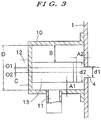
- the treatment, apparatus of the present invention has a vessel 1, preferably of cylindrical shape, and a rotatable body (rotor) 2 mounted to undergo rotation in the vessel.
- the vessel 1 has a supply port 3 which receives slurry composed of a pre-mixed and pre-kneaded treatment material and an internal flow-out port 4 through which the slurry flows out of the vessel.
- a jacket through which circulates a temperature-controlling medium such as cooling water is disposed around the vessel 1.
- the rotatable body 2 is rotated by a driving shaft 5 connected to a driving motor (not shown).
- An annular fine gap 6 is formed between an inner wall face of the vessel 1 and an outer periphery face of the rotatable body 2.
- the treatment material supplied into the vessel 1 from the supply port 3 flows into the annular fine gap 6.
- the size of the annular fine gap 6 is about 1.0 to 10 mm, preferably about 2.0 to 5.0 mm.
- the treatment material to be supplied into the vessel is optimally a viscous paste of from a low viscosity to a medium viscosity within a viscosity range of about 1 to 100 dPa ⁇ s.
- the rotatable body 2 is formed in a tubular shape of circular cross section, and the treatment material continuously receives compression and shearing actions in the annular fine gap 6 by rotation of the rotatable body.
- the outer periphery face of the rotatable tubular body 2 is provided with circumferentially spaced-apart projecting portions 8 that extend longitudinally along the length of the rotatable body 2.
- the projecting portions 8 are circumferentially separated from one another by arcuate portions 7 of the outer periphery face of the rotatable body 2 such that the arcuate portions 7 and the projections 8 are alternately arrayed in the circumferential direction around the outer periphery face of the rotatable body. Stated otherwise, the arcuate portions 7 constitute recessed portions alternately arrayed with the projecting portions 8.
- the treatment material is subjected to compression and shearing actions at the projection portions 8 and release and expansion actions at the arcuate portions 7 between the projections portions 8.
- the compression and shearing actions and the release and expansion actions are repeatedly applied to the treatment material as the material flows from the supply port 3 side towards the internal flow-out port 4 side.
- Usual roll mills in which a treatment material is dispersed by use of plural rolls, are generally considered to be an apparatus for dispersing a treatment material by applying compression, shearing and expansion actions to the material, and therefore the actions by the arcuate portions 7 and the projecting portions 8 may be regarded as actions similar to a dispersion treatment with a roll mill and make it possible to obtain fine and uniform pulverization of the treatment material.
- Notches 9 may be formed on the surface of the rotatable body 2 or on the surface of the projecting portions 8 by a knurling process.
- the shape of the notches 9 may be formed to have horizontal lines, a parallel knurl form such as oblique lines, or a twill knurl form such as rectangular, cross or diagonal.
- the fine projections formed by the notches are formed to have a height of about 1 0 to 0.. 1 mm, preferably about 0. 6 to 0.3 mm.
- An ultrasonic chamber 10 having a discharge port 11 is disposed opposite to the internal flow-out port 4 of the vessel 1., In the ultrasonic chamber 10, an ultrasonic horn 13 of an ultrasonic-generating device 12 is disposed, and treatment material flowing into the ultrasonic chamber 10 is irradiated with ultrasonic waves emitted from the ultrasonic horn 13,
- the distance A1 between the side face of the ultrasonic horn 13 at its discharge port 11 side and the inner wall of the ultrasonic chamber 10 at its discharge port 11 side, and the distance A2 between the front end of the ultrasonic horn 13 and the internal flow-out port 4, are preferably within the range of about 2 to 5 mm.
- the distances A1 and A2 are adjusted to be the same. It should be noted that the distances A1 and A2 need not be equal though each should preferably be within the range 2 to 5 mm.
- the optimum amplitude of ultrasonic waves for generating fine bubbles by cavitation depends on the type of liquid of the treatment material. It is known that cavitation is caused easily in a liquid of the treatment material that has a large surface tension. In general, when the liquid is of a solvent type, the surface tension is as low as roughly 20 to 30 mN/m, and therefore cavitation is hardly generated.. On the other hand, when the liquid is of an aqueous type, the surface tension is 73 mN/m, and therefore cavitation is easily generated.
- the output of the ultrasonic-generating device 12 is 600 W
- the frequency is 20 kHz
- the diameter at the front end portion of the ultrasonic horn 13 is 36 mm
- the amplitude of vibration is 14 to 40 ⁇ m
- cavitation is always generated regardless of the amplitude value.
- the clumps or agglomerates of treatment material can be broken up and disintegrated by the impact forces.
- the internal flow-out port 4 has an orifice through which the treatment material flows out, and the orifice is preferably formed in a shape similar to the shape of the confronting front end portion of the ultrasonic horn 13.
- the diameter of the internal flow-out port 4 is preferably formed to be smaller than the size of the front end portion of the ultrasonic horn 13 so that the treatment material flowing out of the internal flow-out port 4 can be appropriately irradiated with ultrasonic waves.
- the diameter d1 of the internal flow-out port 4 is desirably about 80% of the diameter d2 of the front end portion of the ultrasonic horn 13.
- d1 is formed larger than this level, the presence of clumps or agglomerates is observed in the treatment material discharged from the discharge port 11. At most, d1 is up to the same level as the diameter of the front end portion of the ultrasonic horn.
- the treatment material may undesirably flow out without receiving the ultrasonic treatment by a so-called short pass. Namely, if the position of the discharge port. 11 is close to the position of the internal flow-out port 4 in the ultrasonic chamber 10, and if the distance between the front end portion of the ultrasonic horn 13 disposed at the central position of the ultrasonic chamber 10 and the internal flow-out port 4 is equal to the distance between the side face of the ultrasonic horn 13 and the discharge port 11, the treatment material tends to undergo short pass from the internal flow out port 4 to the discharge port 11.
- the ultrasonic horn 13 is disposed eccentrically to the center 01 of the ultrasonic chamber 10 so that the distance B between the side wall of the ultrasonic horn 13 on the opposite side to the discharge port. 11 and the inner face of the ultrasonic chamber becomes greater than the distance A1 between the side face of the ultrasonic horn 13 at the discharge port 11 side and the discharge port 11, the flow resistance is lowered and control can suitably be made without formation of short pass.
- This structure will be explained below.
- the distance A1 between the side face of the ultrasonic horn 13 at the discharge port 11 side and the inner wall of the ultrasonic chamber 10 is shorter than the distance B between the side face of the ultrasonic horn 13 on the opposite side to the discharge port 11 and the inner wall of the ultrasonic chamber 10.
- aqueous material for an anode of a lithium ion secondary battery which is a mixture of an aqueous solvent and an electrode material containing nano powder (mixed solid materials), was subjected to premixing with a mixer to prepare a slurry liquid.
- This slurry liquid contained a powder of nano powder.
- An apparatus the same as shown in Fig. 1 was used with an ultrasonic device having an output of 600 W, a frequency of 20 kHz, a diameter at the front end portion of the ultrasonic horn of 36 mm, an amplitude of vibration of 40 ⁇ m, and a diameter at the internal flow-out port of 28 mm.
- aqueous material for an anode of a lithium ion secondary battery was subjected to premixing with a mixer to prepare a slurry liquid.
- a treatment apparatus an apparatus the same as illustrated in Fig. 1 was used except that the ultrasonic chamber was removed. In the treated material discharged from the vessel, agglomerated clumps remained and were easily recognized.
- the ultrasonic horn is arranged so that the distance A1 between the side face of the ultrasonic horn at its discharge port side and the inner wall of the ultrasonic chamber and the distance A2 between the front end of the ultrasonic horn and the internal flow-out port are about 2 to 5 mm, preferably 3 to 5 mm, the clumps are disintegrated and at the same time, the temperature of the treatment material is not raised,
Landscapes
- Chemical & Material Sciences (AREA)
- Chemical Kinetics & Catalysis (AREA)
- Dispersion Chemistry (AREA)
- Engineering & Computer Science (AREA)
- Health & Medical Sciences (AREA)
- Organic Chemistry (AREA)
- Combustion & Propulsion (AREA)
- Toxicology (AREA)
- Food Science & Technology (AREA)
- Physical Or Chemical Processes And Apparatus (AREA)
- Crushing And Grinding (AREA)
- Disintegrating Or Milling (AREA)
- Mixers With Rotating Receptacles And Mixers With Vibration Mechanisms (AREA)
Claims (16)
- Verfahren zur Behandlung von Aufschlämmungsbehandlungsmaterial, umfassend die Schritte: Fließenlassen eines Behandlungsmaterials, das feste, in Flüssigkeit gemischte Teilchen enthält, durch eine Zuführöffnung (3) eines Gefäßes (1) in einen ringförmigen feinen Spalt (6), der zwischen einem drehbaren Körper (2) und einer Innenwand des Gefäßes (1) gebildet ist; Drehen des drehbaren Körpers, um Kompressions-, Expansions- und Scherbehandlungen des Behandlungsmaterials in dem ringförmigen feinen Spalt (6) durchzuführen, um die festen Teilchen in dem Behandlungsmaterial fein zu pulverisieren; Abgeben des durch den ringförmigen feinen Spalt (6) hindurchgetretenen Behandlungsmaterials aus einer internen Ausströmöffnung (4) des Gefäßes (1) in eine Ultraschallkammer (10), die eine Auslassöffnung (11) aufweist; Anordnen eines Ultraschallhorns (13) in der Ultraschallkammer in einem Abstand von 2 bis 5 mm von einer Wandfläche der Ultraschallkammer (10) an der Auslassöffnungsseite und in einem Abstand von 2 bis 5 mm von der internen Ausströmöffnung (4); und Bestrahlen des in der Ultraschallkammer (10) fließenden Behandlungsmaterials mit Ultraschallwellen unter Verwendung des Ultraschallhorns (13).
- Verfahren nach Anspruch 1; wobei der Anordnungsschritt das Anordnen des Ultraschallhorns (13) exzentrisch zur Mitte der Ultraschallkammer (10) in Richtung der Auslassöffnungsseite umfasst.
- Verfahren nach Anspruch 1; wobei der Anordnungsschritt das Anordnen des Ultraschallhorns (13) im gleichen Abstand von sowohl der Wandfläche der Ultraschallkammer als auch der internen Ausströmöffnung (4) umfasst.
- Verfahren nach Anspruch 1; wobei der Anordnungsschritt das Fließen eines Behandlungsmaterials umfasst, das feste, in Flüssigkeit gemischte Teilchen enthält, wobei die Flüssigkeit einen Viskositätsbereich von 1 bis 100 dPa · s aufweist.
- Verfahren nach Anspruch 1; wobei der Rotationsschritt ohne Verwendung von Dispersionsmedien ausgeführt wird.
- Verfahren nach Anspruch 1; wobei der Bestrahlungsschritt das Bestrahlen des Behandlungsmaterials mit Ultraschallwellen umfasst, um in der Flüssigkeit des Materials Kavitationsblasen zu erzeugen, die zusammenfallen und Stoßwellen erzeugen, die wirksam sind, um agglomerierte Klumpen fester Teilchen, die im Behandlungsmaterial vorhanden sind, zu zersetzen.
- Verfahren nach Anspruch 6; wobei das Behandlungsmaterial eine Mischung aus festen Teilchen verschiedener Materialien umfasst, die in Flüssigkeit gemischt sind.
- Verfahren nach Anspruch 6; wobei das Behandlungsmaterial Nanopulver enthält.
- Vorrichtung zum Behandeln von Aufschlämmungsbehandlungsmaterial, umfassend: ein Gefäß (1) mit einer Zuführöffnung (3) zum Zuführen von Aufschlämmungsbehandlungsmaterial in das Gefäß und einer internen Ausströmöffnung (4) zum Abführen des Aufschlämmungsbehandlungsmaterials aus dem Gefäß (1); einen drehbaren Körper (2), der drehbar in dem Gefäß (1) angeordnet ist, um einen ringförmigen feinen Spalt (6) zwischen einer äußeren Umfangsfläche des drehbaren Körpers (2) und einer inneren Wandfläche des Gefäßes (1) zu bilden, wobei die Drehung des drehbaren Körpers (2) Kompressions-, Expansions- und Scherbehandlungen des Aufschlämmungsbehandlungsmaterials in dem ringförmigen feinen Spalt (6) durchführt, um die festen Teilchen in dem Behandlungsmaterial fein zu pulverisieren; eine Ultraschallkammer (10), die in Verbindung mit der internen Ausströmöffnung (4) des Gefäßes angeordnet ist und eine Auslassöffnung (11) aufweist; und ein Ultraschallhorn (13), das in der Ultraschallkammer (10) angeordnet ist, wobei das Ultraschallhorn (13) in der Nähe der Auslassöffnungsseite angeordnet ist, so dass der Abstand zwischen dem Ultraschallhorn (13) und der internen Ausströmöffnung (4) 2 bis 5 mm beträgt und der Abstand zwischen dem Ultraschallhorn (13) und einer Wandfläche der Ultraschallkammer (10) 2 bis 5 mm beträgt.
- Vorrichtung nach Anspruch 9; wobei der Mittelpunkt des Ultraschallhorns (13) exzentrisch zum Mittelpunkt der Ultraschallkammer (10) in Richtung der Auslassöffnungsseite angeordnet ist.
- Vorrichtung nach Anspruch 9; wobei die Außenumfangsfläche des drehbaren Körpers (2) mit in Umfangsrichtung beabstandeten vorstehenden Abschnitten (8) versehen ist, die sich in Längsrichtung entlang der Länge des drehbaren Körpers erstrecken.
- Vorrichtung nach Anspruch 11; wobei Kerben (9) an der Oberfläche der vorspringenden Abschnitte (8) des drehbaren Körpers (2) ausgebildet sind.
- Vorrichtung nach Anspruch 9; wobei der ringförmige feine Spalt (6) während des Gebrauchs der Vorrichtung frei von Dispersionsmedien ist.
- Vorrichtung nach Anspruch 9; wobei das Ultraschallhorn (13) im gleichen Abstand von sowohl der Wandfläche der Ultraschallkammer (10) als auch der internen Ausströmöffnung (4) angeordnet ist.
- Vorrichtung nach Anspruch 9; wobei der drehbare Körper (2) bogenförmige Abschnitte (7) und vorstehende Abschnitte (8) aufweist, die abwechselnd in Umfangsrichtung um die äußere Umfangsfläche des drehbaren Körpers angeordnet sind.
- Vorrichtung nach Anspruch 15; wobei sich die bogenförmigen Abschnitte (7) und die vorstehenden Abschnitte (8) in Längsrichtung im Wesentlichen entlang der gesamten Länge des drehbaren Körpers (2) erstrecken.
Applications Claiming Priority (1)
| Application Number | Priority Date | Filing Date | Title |
|---|---|---|---|
| JP2014184793A JP6267609B2 (ja) | 2014-09-11 | 2014-09-11 | スラリーの処理方法及びそれに用いる処理装置 |
Publications (2)
| Publication Number | Publication Date |
|---|---|
| EP2995370A1 EP2995370A1 (de) | 2016-03-16 |
| EP2995370B1 true EP2995370B1 (de) | 2019-02-06 |
Family
ID=53191462
Family Applications (1)
| Application Number | Title | Priority Date | Filing Date |
|---|---|---|---|
| EP15162735.3A Active EP2995370B1 (de) | 2014-09-11 | 2015-04-08 | Verfahren zur behandlung von schlämmen und behandlungsvorrichtung dafür |
Country Status (6)
| Country | Link |
|---|---|
| US (1) | US9675951B2 (de) |
| EP (1) | EP2995370B1 (de) |
| JP (1) | JP6267609B2 (de) |
| KR (1) | KR101680653B1 (de) |
| CN (1) | CN105413834B (de) |
| ES (1) | ES2717786T3 (de) |
Families Citing this family (2)
| Publication number | Priority date | Publication date | Assignee | Title |
|---|---|---|---|---|
| CN110833790A (zh) * | 2019-12-30 | 2020-02-25 | 安徽中创电子信息材料有限公司 | 一种解聚电子功能陶瓷团聚粉体的装置及方法 |
| DE102022109533A1 (de) * | 2022-04-20 | 2023-10-26 | Axalta Coating Systems Gmbh | Verfahren zur Reparatur einer Lackzusammensetzung und Verwendung von Schallwellen zur Reparatur einer Lackzusammensetzung |
Family Cites Families (13)
| Publication number | Priority date | Publication date | Assignee | Title |
|---|---|---|---|---|
| JPS5588865A (en) * | 1978-12-28 | 1980-07-04 | Enajii Ando Mineraruzu Researc | Ultrasoniccwave system crusher |
| US4412842A (en) * | 1979-04-26 | 1983-11-01 | Eric Charles Cottell | Coal beneficiation process |
| DE3535922C2 (de) * | 1984-10-09 | 1999-01-14 | Mitsubishi Chem Corp | Verfahren zur Reinigung von Ruß unter Verwendung einer Ultraschallvibrations-Siebvorrichtung |
| JPS61153115A (ja) * | 1984-12-26 | 1986-07-11 | Mitsubishi Chem Ind Ltd | 超音波濾過機及び濾別方法 |
| JPH0341791Y2 (de) * | 1985-08-29 | 1991-09-02 | ||
| US5035363A (en) * | 1990-07-06 | 1991-07-30 | Thiokol Corporation | Ultrasonic grinding of explosives |
| US6604849B2 (en) * | 1999-12-03 | 2003-08-12 | Taiwan Semiconductor Manufacturing Co., Ltd. | Slurry dilution system with an ultrasonic vibrator capable of in-situ adjustment of slurry concentration |
| JP2001334165A (ja) * | 2000-05-26 | 2001-12-04 | Hitachi Cable Ltd | 粉体の微粉砕方法 |
| CN1878602A (zh) * | 2003-11-28 | 2006-12-13 | 三菱化学株式会社 | 有机化合物微粒的制造方法 |
| JP4993875B2 (ja) * | 2005-05-06 | 2012-08-08 | 富士フイルム株式会社 | 凝集ナノ粒子の分散方法 |
| JP5144086B2 (ja) * | 2007-02-20 | 2013-02-13 | 独立行政法人物質・材料研究機構 | 分散または粉砕装置及び分散または粉砕方法 |
| JP5598824B2 (ja) * | 2012-10-02 | 2014-10-01 | 独立行政法人物質・材料研究機構 | 分散または粉砕装置及び分散または粉砕方法 |
| JP6023541B2 (ja) * | 2012-10-12 | 2016-11-09 | 株式会社井上製作所 | 高粘性流体の処理装置 |
-
2014
- 2014-09-11 JP JP2014184793A patent/JP6267609B2/ja active Active
-
2015
- 2015-02-18 US US14/624,830 patent/US9675951B2/en active Active
- 2015-03-12 KR KR1020150034491A patent/KR101680653B1/ko active Active
- 2015-04-08 ES ES15162735T patent/ES2717786T3/es active Active
- 2015-04-08 EP EP15162735.3A patent/EP2995370B1/de active Active
- 2015-04-15 CN CN201510177782.0A patent/CN105413834B/zh active Active
Non-Patent Citations (1)
| Title |
|---|
| None * |
Also Published As
| Publication number | Publication date |
|---|---|
| JP6267609B2 (ja) | 2018-01-24 |
| CN105413834B (zh) | 2017-12-29 |
| KR20160030826A (ko) | 2016-03-21 |
| EP2995370A1 (de) | 2016-03-16 |
| KR101680653B1 (ko) | 2016-11-29 |
| CN105413834A (zh) | 2016-03-23 |
| US9675951B2 (en) | 2017-06-13 |
| ES2717786T3 (es) | 2019-06-25 |
| JP2016055263A (ja) | 2016-04-21 |
| US20160074826A1 (en) | 2016-03-17 |
Similar Documents
| Publication | Publication Date | Title |
|---|---|---|
| EP1961486B1 (de) | Dispersions- und Mahlvorrichtung und Dispersions- und Mahlverfahren | |
| KR100901429B1 (ko) | 탄소나노튜브 분산을 위한 막힘 방지 기능을 가진 분쇄 및분산 장치 | |
| JP5598824B2 (ja) | 分散または粉砕装置及び分散または粉砕方法 | |
| CN104411392A (zh) | 搅拌机 | |
| US6585180B2 (en) | Pipeline beads mill and dispersing system having the pipeline beads mill | |
| TW201737992A (zh) | 用於混合、特別是分散的裝置和方法 | |
| EP3957391B1 (de) | Rührer | |
| EP2995370B1 (de) | Verfahren zur behandlung von schlämmen und behandlungsvorrichtung dafür | |
| KR102334946B1 (ko) | 쿨링시스템이 구비된 로터-로터방식 임펠러구조 | |
| JP6423988B2 (ja) | 攪拌ミル及びスラリー中粒子の分散方法 | |
| KR20200034654A (ko) | 분산기와, 슬러리 중 입자의 분산 방법 및 에멀젼 제조 방법 | |
| KR102081216B1 (ko) | 분쇄 분산기 | |
| KR20130042287A (ko) | 중·고점도 분쇄 시스템 | |
| JP2005169340A (ja) | 横型湿式媒体撹拌分散粉砕装置 | |
| JP4947470B2 (ja) | ナノ粒子スラリーの分散・凝集制御方法 | |
| EP1741761A2 (de) | Carbon Black Anstrich und Verfahren zu dessen Herstellung | |
| TWI755413B (zh) | 分散機與漿體中粒子的分散方法以及乳化製造方法 | |
| JPH08173826A (ja) | 湿式分散粉砕装置及び方法 | |
| KR101477555B1 (ko) | 고점성 유체의 처리 장치 | |
| KR20200101603A (ko) | 초음파 스트리밍 및 충격파를 이용한 나노입자 분산장치 | |
| JP2004105844A (ja) | 媒体攪拌型2軸粉砕機及び粉砕方法 | |
| JP2002204969A (ja) | パイプラインビ−ズミル | |
| JP2004050161A (ja) | 微小な粒子の粉砕及び分散装置 |
Legal Events
| Date | Code | Title | Description |
|---|---|---|---|
| PUAI | Public reference made under article 153(3) epc to a published international application that has entered the european phase |
Free format text: ORIGINAL CODE: 0009012 |
|
| AK | Designated contracting states |
Kind code of ref document: A1 Designated state(s): AL AT BE BG CH CY CZ DE DK EE ES FI FR GB GR HR HU IE IS IT LI LT LU LV MC MK MT NL NO PL PT RO RS SE SI SK SM TR |
|
| AX | Request for extension of the european patent |
Extension state: BA ME |
|
| 17P | Request for examination filed |
Effective date: 20160913 |
|
| RBV | Designated contracting states (corrected) |
Designated state(s): AL AT BE BG CH CY CZ DE DK EE ES FI FR GB GR HR HU IE IS IT LI LT LU LV MC MK MT NL NO PL PT RO RS SE SI SK SM TR |
|
| RIC1 | Information provided on ipc code assigned before grant |
Ipc: B01F 3/12 20060101ALI20180628BHEP Ipc: B01J 8/40 20060101ALI20180628BHEP Ipc: B01F 13/10 20060101ALI20180628BHEP Ipc: B01F 7/00 20060101AFI20180628BHEP Ipc: B01F 11/02 20060101ALI20180628BHEP |
|
| GRAP | Despatch of communication of intention to grant a patent |
Free format text: ORIGINAL CODE: EPIDOSNIGR1 |
|
| STAA | Information on the status of an ep patent application or granted ep patent |
Free format text: STATUS: GRANT OF PATENT IS INTENDED |
|
| INTG | Intention to grant announced |
Effective date: 20180815 |
|
| GRAS | Grant fee paid |
Free format text: ORIGINAL CODE: EPIDOSNIGR3 |
|
| GRAA | (expected) grant |
Free format text: ORIGINAL CODE: 0009210 |
|
| STAA | Information on the status of an ep patent application or granted ep patent |
Free format text: STATUS: THE PATENT HAS BEEN GRANTED |
|
| AK | Designated contracting states |
Kind code of ref document: B1 Designated state(s): AL AT BE BG CH CY CZ DE DK EE ES FI FR GB GR HR HU IE IS IT LI LT LU LV MC MK MT NL NO PL PT RO RS SE SI SK SM TR |
|
| REG | Reference to a national code |
Ref country code: GB Ref legal event code: FG4D |
|
| REG | Reference to a national code |
Ref country code: CH Ref legal event code: EP Ref country code: AT Ref legal event code: REF Ref document number: 1094505 Country of ref document: AT Kind code of ref document: T Effective date: 20190215 |
|
| REG | Reference to a national code |
Ref country code: IE Ref legal event code: FG4D |
|
| REG | Reference to a national code |
Ref country code: DE Ref legal event code: R096 Ref document number: 602015024260 Country of ref document: DE |
|
| REG | Reference to a national code |
Ref country code: CH Ref legal event code: NV Representative=s name: SCHMAUDER AND PARTNER AG PATENT- UND MARKENANW, CH |
|
| REG | Reference to a national code |
Ref country code: NL Ref legal event code: MP Effective date: 20190206 |
|
| REG | Reference to a national code |
Ref country code: ES Ref legal event code: FG2A Ref document number: 2717786 Country of ref document: ES Kind code of ref document: T3 Effective date: 20190625 Ref country code: LT Ref legal event code: MG4D |
|
| PG25 | Lapsed in a contracting state [announced via postgrant information from national office to epo] |
Ref country code: PT Free format text: LAPSE BECAUSE OF FAILURE TO SUBMIT A TRANSLATION OF THE DESCRIPTION OR TO PAY THE FEE WITHIN THE PRESCRIBED TIME-LIMIT Effective date: 20190606 Ref country code: NL Free format text: LAPSE BECAUSE OF FAILURE TO SUBMIT A TRANSLATION OF THE DESCRIPTION OR TO PAY THE FEE WITHIN THE PRESCRIBED TIME-LIMIT Effective date: 20190206 Ref country code: NO Free format text: LAPSE BECAUSE OF FAILURE TO SUBMIT A TRANSLATION OF THE DESCRIPTION OR TO PAY THE FEE WITHIN THE PRESCRIBED TIME-LIMIT Effective date: 20190506 Ref country code: LT Free format text: LAPSE BECAUSE OF FAILURE TO SUBMIT A TRANSLATION OF THE DESCRIPTION OR TO PAY THE FEE WITHIN THE PRESCRIBED TIME-LIMIT Effective date: 20190206 Ref country code: FI Free format text: LAPSE BECAUSE OF FAILURE TO SUBMIT A TRANSLATION OF THE DESCRIPTION OR TO PAY THE FEE WITHIN THE PRESCRIBED TIME-LIMIT Effective date: 20190206 Ref country code: SE Free format text: LAPSE BECAUSE OF FAILURE TO SUBMIT A TRANSLATION OF THE DESCRIPTION OR TO PAY THE FEE WITHIN THE PRESCRIBED TIME-LIMIT Effective date: 20190206 |
|
| REG | Reference to a national code |
Ref country code: AT Ref legal event code: MK05 Ref document number: 1094505 Country of ref document: AT Kind code of ref document: T Effective date: 20190206 |
|
| PG25 | Lapsed in a contracting state [announced via postgrant information from national office to epo] |
Ref country code: GR Free format text: LAPSE BECAUSE OF FAILURE TO SUBMIT A TRANSLATION OF THE DESCRIPTION OR TO PAY THE FEE WITHIN THE PRESCRIBED TIME-LIMIT Effective date: 20190507 Ref country code: BG Free format text: LAPSE BECAUSE OF FAILURE TO SUBMIT A TRANSLATION OF THE DESCRIPTION OR TO PAY THE FEE WITHIN THE PRESCRIBED TIME-LIMIT Effective date: 20190506 Ref country code: HR Free format text: LAPSE BECAUSE OF FAILURE TO SUBMIT A TRANSLATION OF THE DESCRIPTION OR TO PAY THE FEE WITHIN THE PRESCRIBED TIME-LIMIT Effective date: 20190206 Ref country code: RS Free format text: LAPSE BECAUSE OF FAILURE TO SUBMIT A TRANSLATION OF THE DESCRIPTION OR TO PAY THE FEE WITHIN THE PRESCRIBED TIME-LIMIT Effective date: 20190206 Ref country code: IS Free format text: LAPSE BECAUSE OF FAILURE TO SUBMIT A TRANSLATION OF THE DESCRIPTION OR TO PAY THE FEE WITHIN THE PRESCRIBED TIME-LIMIT Effective date: 20190606 Ref country code: LV Free format text: LAPSE BECAUSE OF FAILURE TO SUBMIT A TRANSLATION OF THE DESCRIPTION OR TO PAY THE FEE WITHIN THE PRESCRIBED TIME-LIMIT Effective date: 20190206 |
|
| PG25 | Lapsed in a contracting state [announced via postgrant information from national office to epo] |
Ref country code: IT Free format text: LAPSE BECAUSE OF FAILURE TO SUBMIT A TRANSLATION OF THE DESCRIPTION OR TO PAY THE FEE WITHIN THE PRESCRIBED TIME-LIMIT Effective date: 20190206 Ref country code: RO Free format text: LAPSE BECAUSE OF FAILURE TO SUBMIT A TRANSLATION OF THE DESCRIPTION OR TO PAY THE FEE WITHIN THE PRESCRIBED TIME-LIMIT Effective date: 20190206 Ref country code: CZ Free format text: LAPSE BECAUSE OF FAILURE TO SUBMIT A TRANSLATION OF THE DESCRIPTION OR TO PAY THE FEE WITHIN THE PRESCRIBED TIME-LIMIT Effective date: 20190206 Ref country code: SK Free format text: LAPSE BECAUSE OF FAILURE TO SUBMIT A TRANSLATION OF THE DESCRIPTION OR TO PAY THE FEE WITHIN THE PRESCRIBED TIME-LIMIT Effective date: 20190206 Ref country code: AL Free format text: LAPSE BECAUSE OF FAILURE TO SUBMIT A TRANSLATION OF THE DESCRIPTION OR TO PAY THE FEE WITHIN THE PRESCRIBED TIME-LIMIT Effective date: 20190206 Ref country code: EE Free format text: LAPSE BECAUSE OF FAILURE TO SUBMIT A TRANSLATION OF THE DESCRIPTION OR TO PAY THE FEE WITHIN THE PRESCRIBED TIME-LIMIT Effective date: 20190206 Ref country code: DK Free format text: LAPSE BECAUSE OF FAILURE TO SUBMIT A TRANSLATION OF THE DESCRIPTION OR TO PAY THE FEE WITHIN THE PRESCRIBED TIME-LIMIT Effective date: 20190206 |
|
| REG | Reference to a national code |
Ref country code: DE Ref legal event code: R097 Ref document number: 602015024260 Country of ref document: DE |
|
| PG25 | Lapsed in a contracting state [announced via postgrant information from national office to epo] |
Ref country code: SM Free format text: LAPSE BECAUSE OF FAILURE TO SUBMIT A TRANSLATION OF THE DESCRIPTION OR TO PAY THE FEE WITHIN THE PRESCRIBED TIME-LIMIT Effective date: 20190206 Ref country code: PL Free format text: LAPSE BECAUSE OF FAILURE TO SUBMIT A TRANSLATION OF THE DESCRIPTION OR TO PAY THE FEE WITHIN THE PRESCRIBED TIME-LIMIT Effective date: 20190206 |
|
| PLBE | No opposition filed within time limit |
Free format text: ORIGINAL CODE: 0009261 |
|
| STAA | Information on the status of an ep patent application or granted ep patent |
Free format text: STATUS: NO OPPOSITION FILED WITHIN TIME LIMIT |
|
| REG | Reference to a national code |
Ref country code: BE Ref legal event code: MM Effective date: 20190430 |
|
| PG25 | Lapsed in a contracting state [announced via postgrant information from national office to epo] |
Ref country code: LU Free format text: LAPSE BECAUSE OF NON-PAYMENT OF DUE FEES Effective date: 20190408 Ref country code: MC Free format text: LAPSE BECAUSE OF FAILURE TO SUBMIT A TRANSLATION OF THE DESCRIPTION OR TO PAY THE FEE WITHIN THE PRESCRIBED TIME-LIMIT Effective date: 20190206 Ref country code: AT Free format text: LAPSE BECAUSE OF FAILURE TO SUBMIT A TRANSLATION OF THE DESCRIPTION OR TO PAY THE FEE WITHIN THE PRESCRIBED TIME-LIMIT Effective date: 20190206 |
|
| 26N | No opposition filed |
Effective date: 20191107 |
|
| PG25 | Lapsed in a contracting state [announced via postgrant information from national office to epo] |
Ref country code: SI Free format text: LAPSE BECAUSE OF FAILURE TO SUBMIT A TRANSLATION OF THE DESCRIPTION OR TO PAY THE FEE WITHIN THE PRESCRIBED TIME-LIMIT Effective date: 20190206 Ref country code: BE Free format text: LAPSE BECAUSE OF NON-PAYMENT OF DUE FEES Effective date: 20190430 |
|
| PG25 | Lapsed in a contracting state [announced via postgrant information from national office to epo] |
Ref country code: TR Free format text: LAPSE BECAUSE OF FAILURE TO SUBMIT A TRANSLATION OF THE DESCRIPTION OR TO PAY THE FEE WITHIN THE PRESCRIBED TIME-LIMIT Effective date: 20190206 |
|
| PG25 | Lapsed in a contracting state [announced via postgrant information from national office to epo] |
Ref country code: IE Free format text: LAPSE BECAUSE OF NON-PAYMENT OF DUE FEES Effective date: 20190408 |
|
| PG25 | Lapsed in a contracting state [announced via postgrant information from national office to epo] |
Ref country code: CY Free format text: LAPSE BECAUSE OF FAILURE TO SUBMIT A TRANSLATION OF THE DESCRIPTION OR TO PAY THE FEE WITHIN THE PRESCRIBED TIME-LIMIT Effective date: 20190206 |
|
| PG25 | Lapsed in a contracting state [announced via postgrant information from national office to epo] |
Ref country code: HU Free format text: LAPSE BECAUSE OF FAILURE TO SUBMIT A TRANSLATION OF THE DESCRIPTION OR TO PAY THE FEE WITHIN THE PRESCRIBED TIME-LIMIT; INVALID AB INITIO Effective date: 20150408 Ref country code: MT Free format text: LAPSE BECAUSE OF FAILURE TO SUBMIT A TRANSLATION OF THE DESCRIPTION OR TO PAY THE FEE WITHIN THE PRESCRIBED TIME-LIMIT Effective date: 20190206 |
|
| REG | Reference to a national code |
Ref country code: DE Ref legal event code: R079 Ref document number: 602015024260 Country of ref document: DE Free format text: PREVIOUS MAIN CLASS: B01F0007000000 Ipc: B01F0027000000 |
|
| PG25 | Lapsed in a contracting state [announced via postgrant information from national office to epo] |
Ref country code: MK Free format text: LAPSE BECAUSE OF FAILURE TO SUBMIT A TRANSLATION OF THE DESCRIPTION OR TO PAY THE FEE WITHIN THE PRESCRIBED TIME-LIMIT Effective date: 20190206 |
|
| PGFP | Annual fee paid to national office [announced via postgrant information from national office to epo] |
Ref country code: DE Payment date: 20250428 Year of fee payment: 11 |
|
| PGFP | Annual fee paid to national office [announced via postgrant information from national office to epo] |
Ref country code: ES Payment date: 20250505 Year of fee payment: 11 |
|
| PGFP | Annual fee paid to national office [announced via postgrant information from national office to epo] |
Ref country code: FR Payment date: 20250426 Year of fee payment: 11 |
|
| PGFP | Annual fee paid to national office [announced via postgrant information from national office to epo] |
Ref country code: CH Payment date: 20250501 Year of fee payment: 11 |
|
| PGFP | Annual fee paid to national office [announced via postgrant information from national office to epo] |
Ref country code: GB Payment date: 20260309 Year of fee payment: 12 |