EP2995384A1 - Poignee rotative de commutation de pomme de douche - Google Patents
Poignee rotative de commutation de pomme de douche Download PDFInfo
- Publication number
- EP2995384A1 EP2995384A1 EP14804747.5A EP14804747A EP2995384A1 EP 2995384 A1 EP2995384 A1 EP 2995384A1 EP 14804747 A EP14804747 A EP 14804747A EP 2995384 A1 EP2995384 A1 EP 2995384A1
- Authority
- EP
- European Patent Office
- Prior art keywords
- water diversion
- disposed
- spindle
- handle
- water
- Prior art date
- Legal status (The legal status is an assumption and is not a legal conclusion. Google has not performed a legal analysis and makes no representation as to the accuracy of the status listed.)
- Granted
Links
Images



Classifications
-
- B—PERFORMING OPERATIONS; TRANSPORTING
- B05—SPRAYING OR ATOMISING IN GENERAL; APPLYING FLUENT MATERIALS TO SURFACES, IN GENERAL
- B05B—SPRAYING APPARATUS; ATOMISING APPARATUS; NOZZLES
- B05B1/00—Nozzles, spray heads or other outlets, with or without auxiliary devices such as valves, heating means
- B05B1/14—Nozzles, spray heads or other outlets, with or without auxiliary devices such as valves, heating means with multiple outlet openings; with strainers in or outside the outlet opening
- B05B1/16—Nozzles, spray heads or other outlets, with or without auxiliary devices such as valves, heating means with multiple outlet openings; with strainers in or outside the outlet opening having selectively- effective outlets
- B05B1/1627—Nozzles, spray heads or other outlets, with or without auxiliary devices such as valves, heating means with multiple outlet openings; with strainers in or outside the outlet opening having selectively- effective outlets with a selecting mechanism comprising a gate valve, a sliding valve or a cock
- B05B1/1636—Nozzles, spray heads or other outlets, with or without auxiliary devices such as valves, heating means with multiple outlet openings; with strainers in or outside the outlet opening having selectively- effective outlets with a selecting mechanism comprising a gate valve, a sliding valve or a cock by relative rotative movement of the valve elements
-
- B—PERFORMING OPERATIONS; TRANSPORTING
- B05—SPRAYING OR ATOMISING IN GENERAL; APPLYING FLUENT MATERIALS TO SURFACES, IN GENERAL
- B05B—SPRAYING APPARATUS; ATOMISING APPARATUS; NOZZLES
- B05B1/00—Nozzles, spray heads or other outlets, with or without auxiliary devices such as valves, heating means
- B05B1/14—Nozzles, spray heads or other outlets, with or without auxiliary devices such as valves, heating means with multiple outlet openings; with strainers in or outside the outlet opening
- B05B1/18—Roses; Shower heads
-
- B—PERFORMING OPERATIONS; TRANSPORTING
- B05—SPRAYING OR ATOMISING IN GENERAL; APPLYING FLUENT MATERIALS TO SURFACES, IN GENERAL
- B05B—SPRAYING APPARATUS; ATOMISING APPARATUS; NOZZLES
- B05B1/00—Nozzles, spray heads or other outlets, with or without auxiliary devices such as valves, heating means
- B05B1/14—Nozzles, spray heads or other outlets, with or without auxiliary devices such as valves, heating means with multiple outlet openings; with strainers in or outside the outlet opening
- B05B1/18—Roses; Shower heads
- B05B1/188—Roses; Shower heads with user-actuated controlling members
- B05B1/189—Roses; Shower heads with user-actuated controlling members actuated by a rotating movement
-
- B—PERFORMING OPERATIONS; TRANSPORTING
- B05—SPRAYING OR ATOMISING IN GENERAL; APPLYING FLUENT MATERIALS TO SURFACES, IN GENERAL
- B05B—SPRAYING APPARATUS; ATOMISING APPARATUS; NOZZLES
- B05B1/00—Nozzles, spray heads or other outlets, with or without auxiliary devices such as valves, heating means
- B05B1/14—Nozzles, spray heads or other outlets, with or without auxiliary devices such as valves, heating means with multiple outlet openings; with strainers in or outside the outlet opening
- B05B1/18—Roses; Shower heads
- B05B1/188—Roses; Shower heads with user-actuated controlling members
- B05B1/1892—Roses; Shower heads with user-actuated controlling members located in or on the handle
Definitions
- the present invention relates to a rotating switch shower head, especially to a shower head with the rotating switch on the handle.
- An outlet switch device of a shower head is disclosed in the Chinese patent database with announcement number CN201140131Y , therein the inlet port of the shower head main body is disposed with a plurality of inlets corresponding to different water diversion cavities, a connecting element is disposed between the handle of the shower head and the inlet port of the main body, the front end face of the connecting element is disposed with an outlet hole corresponding to the inlets, the connecting element is axially pivoted joint to the inlet port of the main body, the connecting element is fixed to the handle in sealing way.
- the handle can rotate with respect to the main body, so as to drive the connecting element to rotate to make the outlet hole switched to connect to different inlets of the main body.
- the inlet port of the main body is disposed with a plurality of water diversion cavities, making the inlet port of the main body with complicated structure, thick and uneven wall, so that appearance defect like shrinking easily happens during injection molding, and the inlet port of the main body has a large size.
- a handle rotating switch shower head which overcomes the disadvantages of the existing known technology.
- the technical proposal of the present invention is that: a handle rotating switch shower head, comprising:
- it further comprises a sealing element (500), the sealing element (500) is disposed to the spindle (300), the spindle (300) rotates to make the sealing element (500) close one set of water diversion holes or close part of the water diversion holes of at least two sets of the water diversion holes at the same time.
- the head portion (100) comprises a main body (120) and a cover component (130) disposed to the main body (120), the inlets (100) are disposed to the cover component (130), the main body (120) is disposed with a hollow connecting portion (121), the inlets (110) are corresponding to the connecting portion (121), the water diversion cavities (210) extend out of the handle (400) and run through the connecting portion (121) to insert to the main body (120), the water diversion cavities (210) are connected to the inlets (110).
- annular lock groove (211) is disposed at the outer periphery of the water diversion cavity (210), the lock groove (211) is disposed in the main body (12), a lock element (600) is further disposed, the lock element (600) is locked to the lock groove (211), the lateral width of the lock element (600) is larger than that of the connecting portion (121).
- a protruding block (122) is disposed at the inner wall of the connecting portion (121), two adjacent water diversion cavities (210) of the water diversion body (200) is disposed with a groove (212) which can be coupled to the protruding block (122).
- the water diversion body (200) comprises a sleeve portion (220), the bottom end face of the sleeve portion (220) is disposed with the water diversion holes, the water diversion cavities (210) are connected to the sleeve portion (220), one end of the spindle (300) inserts to the sleeve portion (220), while the other end extends out of the sleeve portion (220), the handle (400) is sleeved on the outer side of the spindle (300) and the sleeve portion (220), the periphery wall of the sleeve portion (220) is disposed with a through groove (221), the outer periphery of the end of the spindle (300) inserted to the sleeve portion (220) is disposed with an annular stop groove (320), a stop element (330) is further disposed to limit the spindle (300) in the axial direction, the stop element (330) is assembled to the stop groove (
- the top end portion of the sleeve portion (220) is disposed with a stop block (222), the outer periphery of the spindle (300) is protruding with two stop ribs (340) which can contact with and couple to the stop block (222) so as to limit the rotating angle of the spindle (300).
- the inner periphery face of the handle (400) is protruding with an elongated protruding rib (410), the outer periphery of the spindle (300) is disposed with an elongated groove (350)which can be coupled to the protruding rib (410).
- the outer periphery of the end of the spindle (300) inserted to the sleeve portion (220) is concaved with an assembly chamber (360), the sleeve portion (220) is disposed with at least three lock holes (223), a lock pin (224) and a spring (225) are further disposed, the lock pin (224) is movably assembled to the assembly chamber (360) and can be coupled to the lock holes (223) respectively, the spring (225) abuts against between the lock pin (224) and the assembly chamber (360).
- it comprises two sets of water diversion holes: a first water diversion hole set and a second water diversion hole set, the first water diversion hole set comprises two pairs of first water diversion holes (230), the second water diversion hole set comprises two pairs of second water diversion holes (240); and two water diversion cavities (210), two inlets (110) and two outlet functions.
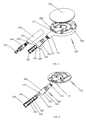
- the handle rotating switch shower head of the preferred embodiment comprises a head portion 100, a water diversion body 200, a spindle 300 and a handle 400.
- the head portion 100 has at least two outlet functions and at least two inlets 110, each of which is corresponding to one outlet function.
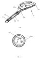
- the head portion 100 comprises shower head main body 120, a cover component 130 fixedly connected to the main body 120 and a rear cover 140, the rear cover covers 140, the main body 120 and forming an accommodating chamber, the cover component 130 is disposed in the accommodating chamber.
- the shower head main body 120 is disposed with a hollow connecting portion 121, two inlets 110 are respectively corresponding to the connecting portion 121.
- the inner wall of the connecting portion 121 is disposed with a protruding block 122.
- the water diversion body 200 is fixedly assembled to the head portion 100, it is disposed with at least two sets of water diversion holes and at least two water diversion cavities 210, each set of the water diversion holes is corresponding to a water diversion cavity 210, the water diversion cavities 210 insert to the head portion 100 and one water diversion cavity 210 is connected to one inlet 110.
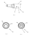
- the water diversion body 200 comprises a sleeve portion 220, the bottom end face of the sleeve portion 220 is disposed with the water diversion holes, the water diversion cavities 210 are fixedly connected to the bottom portion of the sleeve portion 220.
- the periphery of the sleeve portion 220 is disposed with a through groove 221, a groove 212 coupled to the protruding block 122 is disposed between two adjacent water diversion cavities 210, with the protruding block and the groove, it limits the movement of the water diversion cavities in the radial direction; the top portion of the sleeve portion 220 is disposed with a stop block 222, the periphery of the sleeve portion 220 is further disposed with at least three lock holes 223.
- the outer periphery of the first water diversion cavity 210a and the second water diversion cavity 210b is respectively disposed with an annular lock groove 211, the lock grooves 211 are disposed in the main body 120, a chevron shaped lock element 600 is further disposed, the opening end of the chevron shaped lock element 600 is downwardly locked to the two lock grooves 211, the lateral width of the lock element 600 is larger than the width of the connecting portion 121, with the lock element 600, the water diversion cavity 200 can not take off the main body. With the lock element and the lock groove, the water diversion cavities are move limited in the axial direction.
- two water diversion cavities 210 both run through the connecting portion 121 and insert to the main body 120, the water diversion cavities 210 are respectively connected to the inlets 110.
- the end of the water diversion cavities 210 inserts to the inlets 110.
- the spindle 300 is pivoted joint to the water diversion body 200, it is disposed with an inlet passage 310, the spindle 300 rotates to drive the inlet passage 310 to switch to connect to the water diversion holes.
- one end of the spindle 300 inserts to the sleeve portion 200, while the other end extends out of the sleeve portion 220.
- the shower head further comprises a sealing element 500, which is fixedly connected to the end of the spindle 300 inserted to the sleeve portion, the spindle 300 rotates to drive the sealing element 500 to rotate so as to close one set of the water diversion holes or close part of the water diversion holes of the at least two sets of the water diversion holes.
- the sealing element 500 can close the first water diversion hole set or the second water diversion hole set, or in other case, close one pair of the first water diversion holes and one pair of the second water diversion holes at the same time.
- the second water diversion hole set When the first water diversion hole set is closed by the sealing element 500, the second water diversion hole set is connected to the inlet passage, the second water diversion cavity 210b outflows water; When the second water diversion hole set is closed by the sealing element 500, the first water diversion hole set is connected to the inlet passage, the first water diversion cavity 210a outflows water; when one pair of the first water diversion holes and one pair of the second water diversion holes are closed by the sealing element 500, the first and the second water diversion cavities outflow water at the same time.
- the outer periphery of the end of the spindle 300 inserted to the sleeve portion 220 is disposed with an annular stop groove 320, a stop element 330 is further disposed to limit the movement of the spindle 300 in the axial direction, the stop element 330 is assembled to the stop groove 320 and is locked to the through groove 221. with the stop element, the stop groove and the through groove, the spindle is movement limited in the axial direction, the stop structure is simple and low cost.
- the outer periphery of the end of the spindle 300 inserted to the sleeve portion is disposed with an assembly chamber 360, a lock pin 224 and a spring 225 are further disposed, the lock pin 224 is movably assembled to the assembly chamber 360 and it can work with the lock holes 223, the spring 225 abuts against between the lock pin 224 and the assembly chamber 360. with the cooperation of the lock pin, spring and the lock holes, it has gear feeling during switching, so that it has well switch hand feel.
- the outer periphery of the end of the spindle 300 extending out of the sleeve portion is protruding with two stop ribs 340 contacted with and coupled to the stop block 222 so as to limit the rotating angle of the spindle 300.
- the outer periphery of the end of the spindle extending out of the sleeve portion is disposed with an elongated groove 350.
- the handle 400 is rotatable with respect to the water diversion body 200 and is fixed with respect to the spindle 300, the handle 300 is connected to the water diversion body 200 in sleeving way.
- the handle 400 is sleeved on the outer side of the spindle 300 and the sleeve portion 220.
- the inner periphery face of the handle 400 is protruding with an elongated protruding rib 410, the protruding rib 410 is coupled to the elongated groove 350.
- the spindle and the handle rotate synchronously, the structure is simple.
- the shower head is further disposed with a connecting sleeve 700
- the connecting sleeve 700 is disposed with an air suction valve 710
- one end of the connecting sleeve 700 is thread connected to the end of the spindle 300 extending out of the sleeve portion
- the other end of the connecting sleeve 700 extends out of the handle 400 to connect to a water pipe.
- the working principle of the shower head is that:
- the handle 400 drives the spindle 300 to rotate synchronously, the sealing element 500 closes one pair of the first water diversion holes 230 of the first water diversion hole set and one pair of the second water diversion holes 240 of the second water diversion hole set at the same time by the driving of the spindle, at this time, the other pair of the first water diversion holes 230 and the other pair of the second water diversion holes 240 are respectively connected to the first water diversion cavity 210a and the second water diversion cavity 210b, both outlet functions outflow water.
- the handle 400 drives the spindle 300 to rotate synchronously, the sealing element 500 closes the second water diversion hole set by the driving of the spindle, the first water diversion hole set is connected to the inlet passage, the first water diversion cavity 210a outflows water, the outlet function corresponding to the first water diversion cavity 210a outflows water.
- the handle can drive the spindle to rotate with respect to the water diversion body so as to implement function switch, that is to say, the switch device is disposed in the handle, the head portion can be very thin; in addition, the switch device formed by the handle, the spindle and the water diversion body can couple to head portions with different appearance, so that it has well commonality performance.
- the present invention is disposed with at least two outlet holes in the water diversion body to connect to the cover component by big and small holes, rotating the handle to drive the spindle to rotate with respect to the water diversion body so as to implement function switch, that is to say, the switch device is disposed in the handle, the head portion can be very thin; in addition, the switch device formed by the handle, the spindle and the water diversion body can couple to head portions with different appearance, so that it has well commonality performance.
Landscapes
- Bathtubs, Showers, And Their Attachments (AREA)
- Nozzles (AREA)
- Multiple-Way Valves (AREA)
- Domestic Plumbing Installations (AREA)
Applications Claiming Priority (3)
| Application Number | Priority Date | Filing Date | Title |
|---|---|---|---|
| CN2013202967960U CN203316285U (zh) | 2013-05-27 | 2013-05-27 | 一种手柄旋转切换花洒 |
| CN201310202131.3A CN104174515B (zh) | 2013-05-27 | 2013-05-27 | 手柄旋转切换花洒 |
| PCT/CN2014/078407 WO2014190881A1 (fr) | 2013-05-27 | 2014-05-26 | Poignee rotative de commutation de pomme de douche |
Publications (3)
| Publication Number | Publication Date |
|---|---|
| EP2995384A1 true EP2995384A1 (fr) | 2016-03-16 |
| EP2995384A4 EP2995384A4 (fr) | 2017-01-25 |
| EP2995384B1 EP2995384B1 (fr) | 2019-01-09 |
Family
ID=51987995
Family Applications (1)
| Application Number | Title | Priority Date | Filing Date |
|---|---|---|---|
| EP14804747.5A Not-in-force EP2995384B1 (fr) | 2013-05-27 | 2014-05-26 | Poignee rotative de commutation de pomme de douche |
Country Status (3)
| Country | Link |
|---|---|
| US (1) | US9573142B2 (fr) |
| EP (1) | EP2995384B1 (fr) |
| WO (1) | WO2014190881A1 (fr) |
Families Citing this family (3)
| Publication number | Priority date | Publication date | Assignee | Title |
|---|---|---|---|---|
| CN107420587A (zh) * | 2017-06-28 | 2017-12-01 | 恺霖卫浴科技(厦门)有限公司 | 一种流量控制组件及花洒 |
| CA3080909C (fr) | 2019-05-29 | 2025-07-08 | Water Pik, Inc. | Pomme de douche munie d’un support de moteur en ligne |
| USD944923S1 (en) * | 2020-10-20 | 2022-03-01 | Sinyu Technology (Fujian) Co., Ltd. | Shower head |
Family Cites Families (16)
| Publication number | Priority date | Publication date | Assignee | Title |
|---|---|---|---|---|
| DE19509659C1 (de) * | 1995-03-17 | 1996-11-21 | Hansa Metallwerke Ag | Mehrfunktions-Handbrause |
| DE10232463A1 (de) * | 2002-07-17 | 2004-01-29 | Grohe Water Technology Ag & Co. Kg | Handbrause mit integriertem Ventil |
| TWM263159U (en) * | 2004-07-23 | 2005-05-01 | Yuan Mei Corp | Long-tube sprayer structure improvement |
| US6981661B1 (en) * | 2004-07-23 | 2006-01-03 | Shin Tai Spurt Water Of The Garden Tools Co., Ltd. | Spraying gun |
| US7156325B1 (en) * | 2005-01-03 | 2007-01-02 | Shin Tai Spurt Water Of The Garden Tools Co., Ltd. | Spraying gun |
| US7789326B2 (en) * | 2006-12-29 | 2010-09-07 | Water Pik, Inc. | Handheld showerhead with mode control and method of selecting a handheld showerhead mode |
| US7434751B1 (en) * | 2007-01-03 | 2008-10-14 | Shin Tai Spurt Water Of The Garden Tools Co., Ltd. | Water spraying gun having different spraying types |
| CN201140131Y (zh) * | 2007-12-24 | 2008-10-29 | 伟特(厦门)淋浴设备有限公司 | 花洒出水切换装置 |
| US8297538B2 (en) * | 2008-05-23 | 2012-10-30 | Zhou Huasong | Shower switch with adjustable device |
| CN101357354B (zh) * | 2008-09-09 | 2012-05-23 | 厦门松霖科技有限公司 | 兼具龙头功能的花洒结构 |
| US7992806B2 (en) * | 2008-11-14 | 2011-08-09 | Globe Union Industrial Corp. | Showerhead with rotationally adjustable handle |
| CN102069043A (zh) * | 2009-11-25 | 2011-05-25 | 厦门松霖科技有限公司 | 旋转切换花洒及其控制方法 |
| CN201692892U (zh) | 2010-06-17 | 2011-01-05 | 余章军 | 带有滚轮切换的球密封花洒手柄 |
| CN202097046U (zh) | 2011-04-26 | 2012-01-04 | 余章军 | 一种手柄转动切换花洒 |
| CN202752111U (zh) | 2012-08-03 | 2013-02-27 | 厦门建霖工业有限公司 | 花洒功能水切换结构 |
| CN203316285U (zh) | 2013-05-27 | 2013-12-04 | 厦门松霖科技有限公司 | 一种手柄旋转切换花洒 |
-
2014
- 2014-05-26 EP EP14804747.5A patent/EP2995384B1/fr not_active Not-in-force
- 2014-05-26 WO PCT/CN2014/078407 patent/WO2014190881A1/fr not_active Ceased
- 2014-05-26 US US14/786,774 patent/US9573142B2/en not_active Expired - Fee Related
Non-Patent Citations (1)
| Title |
|---|
| See references of WO2014190881A1 * |
Also Published As
| Publication number | Publication date |
|---|---|
| WO2014190881A1 (fr) | 2014-12-04 |
| EP2995384A4 (fr) | 2017-01-25 |
| US9573142B2 (en) | 2017-02-21 |
| US20160074883A1 (en) | 2016-03-17 |
| EP2995384B1 (fr) | 2019-01-09 |
Similar Documents
| Publication | Publication Date | Title |
|---|---|---|
| US11369981B2 (en) | Water outflow control assembly, shower head and shower head assembly method | |
| US10239065B2 (en) | Flow control component and shower | |
| CN210290845U (zh) | 一种多通阀及电动多通阀 | |
| MX2021014886A (es) | Válvula rotativa. | |
| JP5881335B2 (ja) | 流路切換弁 | |
| TWI477362B (zh) | A single tool is used to switch the pneumatic tool that reverses and adjusts the speed | |
| US20220134360A1 (en) | Shower head | |
| US9322417B2 (en) | Motor assembly for pneumatic tool | |
| US9573142B2 (en) | Handle rotating switch shower head | |
| US9175780B2 (en) | Button switch three-way valve | |
| CN110388481A (zh) | 球阀 | |
| CN112013134B (zh) | 一种控制阀 | |
| US20150275669A1 (en) | Air-tight switching device for use in a pneumatic tool | |
| US20120325510A1 (en) | Impact wrench with improved redirection switch | |
| CN104174515B (zh) | 手柄旋转切换花洒 | |
| US9238236B2 (en) | Waterway switch valve set and a shower head using same | |
| CN101907182B (zh) | 一种旋转式切换阀 | |
| EP2848314B1 (fr) | Groupe de vannes commandé par bouton poussoir et pomme de douche utilisant ce groupe de vannes | |
| CN111229487B (zh) | 一种防滴水花洒 | |
| JP6700870B2 (ja) | 流路切換弁 | |
| KR200470170Y1 (ko) | 좌우 클릭형 단 조작수단을 갖는 수도밸브 카트리지 | |
| CN203316285U (zh) | 一种手柄旋转切换花洒 | |
| CN215293714U (zh) | 一种三档流体转换阀 | |
| CN112128426B (zh) | 球阀 | |
| JP2013044410A (ja) | 流路切換弁 |
Legal Events
| Date | Code | Title | Description |
|---|---|---|---|
| PUAI | Public reference made under article 153(3) epc to a published international application that has entered the european phase |
Free format text: ORIGINAL CODE: 0009012 |
|
| 17P | Request for examination filed |
Effective date: 20151210 |
|
| AK | Designated contracting states |
Kind code of ref document: A1 Designated state(s): AL AT BE BG CH CY CZ DE DK EE ES FI FR GB GR HR HU IE IS IT LI LT LU LV MC MK MT NL NO PL PT RO RS SE SI SK SM TR |
|
| AX | Request for extension of the european patent |
Extension state: BA ME |
|
| DAX | Request for extension of the european patent (deleted) | ||
| A4 | Supplementary search report drawn up and despatched |
Effective date: 20170102 |
|
| RIC1 | Information provided on ipc code assigned before grant |
Ipc: B05B 1/16 20060101AFI20161221BHEP Ipc: B05B 1/18 20060101ALI20161221BHEP |
|
| RAP1 | Party data changed (applicant data changed or rights of an application transferred) |
Owner name: XIAMEN SOLEX HIGH-TECH INDUSTRIES CO., LTD. Owner name: ZHOU, HUASONG |
|
| RAP1 | Party data changed (applicant data changed or rights of an application transferred) |
Owner name: XIAMEN SOLEX HIGH-TECH INDUSTRIES CO., LTD. |
|
| RAP1 | Party data changed (applicant data changed or rights of an application transferred) |
Owner name: XIAMEN SOLEX HIGH-TECH INDUSTRIES CO., LTD. |
|
| GRAP | Despatch of communication of intention to grant a patent |
Free format text: ORIGINAL CODE: EPIDOSNIGR1 |
|
| STAA | Information on the status of an ep patent application or granted ep patent |
Free format text: STATUS: GRANT OF PATENT IS INTENDED |
|
| INTG | Intention to grant announced |
Effective date: 20180719 |
|
| GRAS | Grant fee paid |
Free format text: ORIGINAL CODE: EPIDOSNIGR3 |
|
| GRAA | (expected) grant |
Free format text: ORIGINAL CODE: 0009210 |
|
| STAA | Information on the status of an ep patent application or granted ep patent |
Free format text: STATUS: THE PATENT HAS BEEN GRANTED |
|
| AK | Designated contracting states |
Kind code of ref document: B1 Designated state(s): AL AT BE BG CH CY CZ DE DK EE ES FI FR GB GR HR HU IE IS IT LI LT LU LV MC MK MT NL NO PL PT RO RS SE SI SK SM TR |
|
| REG | Reference to a national code |
Ref country code: GB Ref legal event code: FG4D |
|
| REG | Reference to a national code |
Ref country code: CH Ref legal event code: EP Ref country code: AT Ref legal event code: REF Ref document number: 1086646 Country of ref document: AT Kind code of ref document: T Effective date: 20190115 |
|
| REG | Reference to a national code |
Ref country code: IE Ref legal event code: FG4D |
|
| REG | Reference to a national code |
Ref country code: DE Ref legal event code: R096 Ref document number: 602014039672 Country of ref document: DE |
|
| REG | Reference to a national code |
Ref country code: NL Ref legal event code: MP Effective date: 20190109 |
|
| REG | Reference to a national code |
Ref country code: LT Ref legal event code: MG4D |
|
| PG25 | Lapsed in a contracting state [announced via postgrant information from national office to epo] |
Ref country code: NL Free format text: LAPSE BECAUSE OF FAILURE TO SUBMIT A TRANSLATION OF THE DESCRIPTION OR TO PAY THE FEE WITHIN THE PRESCRIBED TIME-LIMIT Effective date: 20190109 |
|
| REG | Reference to a national code |
Ref country code: AT Ref legal event code: MK05 Ref document number: 1086646 Country of ref document: AT Kind code of ref document: T Effective date: 20190109 |
|
| PG25 | Lapsed in a contracting state [announced via postgrant information from national office to epo] |
Ref country code: FI Free format text: LAPSE BECAUSE OF FAILURE TO SUBMIT A TRANSLATION OF THE DESCRIPTION OR TO PAY THE FEE WITHIN THE PRESCRIBED TIME-LIMIT Effective date: 20190109 Ref country code: NO Free format text: LAPSE BECAUSE OF FAILURE TO SUBMIT A TRANSLATION OF THE DESCRIPTION OR TO PAY THE FEE WITHIN THE PRESCRIBED TIME-LIMIT Effective date: 20190409 Ref country code: PL Free format text: LAPSE BECAUSE OF FAILURE TO SUBMIT A TRANSLATION OF THE DESCRIPTION OR TO PAY THE FEE WITHIN THE PRESCRIBED TIME-LIMIT Effective date: 20190109 Ref country code: LT Free format text: LAPSE BECAUSE OF FAILURE TO SUBMIT A TRANSLATION OF THE DESCRIPTION OR TO PAY THE FEE WITHIN THE PRESCRIBED TIME-LIMIT Effective date: 20190109 Ref country code: ES Free format text: LAPSE BECAUSE OF FAILURE TO SUBMIT A TRANSLATION OF THE DESCRIPTION OR TO PAY THE FEE WITHIN THE PRESCRIBED TIME-LIMIT Effective date: 20190109 Ref country code: PT Free format text: LAPSE BECAUSE OF FAILURE TO SUBMIT A TRANSLATION OF THE DESCRIPTION OR TO PAY THE FEE WITHIN THE PRESCRIBED TIME-LIMIT Effective date: 20190509 Ref country code: SE Free format text: LAPSE BECAUSE OF FAILURE TO SUBMIT A TRANSLATION OF THE DESCRIPTION OR TO PAY THE FEE WITHIN THE PRESCRIBED TIME-LIMIT Effective date: 20190109 |
|
| PG25 | Lapsed in a contracting state [announced via postgrant information from national office to epo] |
Ref country code: LV Free format text: LAPSE BECAUSE OF FAILURE TO SUBMIT A TRANSLATION OF THE DESCRIPTION OR TO PAY THE FEE WITHIN THE PRESCRIBED TIME-LIMIT Effective date: 20190109 Ref country code: GR Free format text: LAPSE BECAUSE OF FAILURE TO SUBMIT A TRANSLATION OF THE DESCRIPTION OR TO PAY THE FEE WITHIN THE PRESCRIBED TIME-LIMIT Effective date: 20190410 Ref country code: RS Free format text: LAPSE BECAUSE OF FAILURE TO SUBMIT A TRANSLATION OF THE DESCRIPTION OR TO PAY THE FEE WITHIN THE PRESCRIBED TIME-LIMIT Effective date: 20190109 Ref country code: BG Free format text: LAPSE BECAUSE OF FAILURE TO SUBMIT A TRANSLATION OF THE DESCRIPTION OR TO PAY THE FEE WITHIN THE PRESCRIBED TIME-LIMIT Effective date: 20190409 Ref country code: IS Free format text: LAPSE BECAUSE OF FAILURE TO SUBMIT A TRANSLATION OF THE DESCRIPTION OR TO PAY THE FEE WITHIN THE PRESCRIBED TIME-LIMIT Effective date: 20190509 Ref country code: HR Free format text: LAPSE BECAUSE OF FAILURE TO SUBMIT A TRANSLATION OF THE DESCRIPTION OR TO PAY THE FEE WITHIN THE PRESCRIBED TIME-LIMIT Effective date: 20190109 |
|
| REG | Reference to a national code |
Ref country code: DE Ref legal event code: R097 Ref document number: 602014039672 Country of ref document: DE |
|
| PG25 | Lapsed in a contracting state [announced via postgrant information from national office to epo] |
Ref country code: AT Free format text: LAPSE BECAUSE OF FAILURE TO SUBMIT A TRANSLATION OF THE DESCRIPTION OR TO PAY THE FEE WITHIN THE PRESCRIBED TIME-LIMIT Effective date: 20190109 Ref country code: DK Free format text: LAPSE BECAUSE OF FAILURE TO SUBMIT A TRANSLATION OF THE DESCRIPTION OR TO PAY THE FEE WITHIN THE PRESCRIBED TIME-LIMIT Effective date: 20190109 Ref country code: AL Free format text: LAPSE BECAUSE OF FAILURE TO SUBMIT A TRANSLATION OF THE DESCRIPTION OR TO PAY THE FEE WITHIN THE PRESCRIBED TIME-LIMIT Effective date: 20190109 Ref country code: SK Free format text: LAPSE BECAUSE OF FAILURE TO SUBMIT A TRANSLATION OF THE DESCRIPTION OR TO PAY THE FEE WITHIN THE PRESCRIBED TIME-LIMIT Effective date: 20190109 Ref country code: CZ Free format text: LAPSE BECAUSE OF FAILURE TO SUBMIT A TRANSLATION OF THE DESCRIPTION OR TO PAY THE FEE WITHIN THE PRESCRIBED TIME-LIMIT Effective date: 20190109 Ref country code: IT Free format text: LAPSE BECAUSE OF FAILURE TO SUBMIT A TRANSLATION OF THE DESCRIPTION OR TO PAY THE FEE WITHIN THE PRESCRIBED TIME-LIMIT Effective date: 20190109 Ref country code: RO Free format text: LAPSE BECAUSE OF FAILURE TO SUBMIT A TRANSLATION OF THE DESCRIPTION OR TO PAY THE FEE WITHIN THE PRESCRIBED TIME-LIMIT Effective date: 20190109 Ref country code: EE Free format text: LAPSE BECAUSE OF FAILURE TO SUBMIT A TRANSLATION OF THE DESCRIPTION OR TO PAY THE FEE WITHIN THE PRESCRIBED TIME-LIMIT Effective date: 20190109 |
|
| PLBE | No opposition filed within time limit |
Free format text: ORIGINAL CODE: 0009261 |
|
| STAA | Information on the status of an ep patent application or granted ep patent |
Free format text: STATUS: NO OPPOSITION FILED WITHIN TIME LIMIT |
|
| PG25 | Lapsed in a contracting state [announced via postgrant information from national office to epo] |
Ref country code: SM Free format text: LAPSE BECAUSE OF FAILURE TO SUBMIT A TRANSLATION OF THE DESCRIPTION OR TO PAY THE FEE WITHIN THE PRESCRIBED TIME-LIMIT Effective date: 20190109 |
|
| 26N | No opposition filed |
Effective date: 20191010 |
|
| REG | Reference to a national code |
Ref country code: CH Ref legal event code: PL |
|
| GBPC | Gb: european patent ceased through non-payment of renewal fee |
Effective date: 20190526 |
|
| PG25 | Lapsed in a contracting state [announced via postgrant information from national office to epo] |
Ref country code: CH Free format text: LAPSE BECAUSE OF NON-PAYMENT OF DUE FEES Effective date: 20190531 Ref country code: MC Free format text: LAPSE BECAUSE OF FAILURE TO SUBMIT A TRANSLATION OF THE DESCRIPTION OR TO PAY THE FEE WITHIN THE PRESCRIBED TIME-LIMIT Effective date: 20190109 Ref country code: LI Free format text: LAPSE BECAUSE OF NON-PAYMENT OF DUE FEES Effective date: 20190531 |
|
| REG | Reference to a national code |
Ref country code: BE Ref legal event code: MM Effective date: 20190531 |
|
| PG25 | Lapsed in a contracting state [announced via postgrant information from national office to epo] |
Ref country code: LU Free format text: LAPSE BECAUSE OF NON-PAYMENT OF DUE FEES Effective date: 20190526 Ref country code: SI Free format text: LAPSE BECAUSE OF FAILURE TO SUBMIT A TRANSLATION OF THE DESCRIPTION OR TO PAY THE FEE WITHIN THE PRESCRIBED TIME-LIMIT Effective date: 20190109 |
|
| PG25 | Lapsed in a contracting state [announced via postgrant information from national office to epo] |
Ref country code: TR Free format text: LAPSE BECAUSE OF FAILURE TO SUBMIT A TRANSLATION OF THE DESCRIPTION OR TO PAY THE FEE WITHIN THE PRESCRIBED TIME-LIMIT Effective date: 20190109 |
|
| PG25 | Lapsed in a contracting state [announced via postgrant information from national office to epo] |
Ref country code: IE Free format text: LAPSE BECAUSE OF NON-PAYMENT OF DUE FEES Effective date: 20190526 Ref country code: GB Free format text: LAPSE BECAUSE OF NON-PAYMENT OF DUE FEES Effective date: 20190526 |
|
| PG25 | Lapsed in a contracting state [announced via postgrant information from national office to epo] |
Ref country code: BE Free format text: LAPSE BECAUSE OF NON-PAYMENT OF DUE FEES Effective date: 20190531 |
|
| PG25 | Lapsed in a contracting state [announced via postgrant information from national office to epo] |
Ref country code: CY Free format text: LAPSE BECAUSE OF FAILURE TO SUBMIT A TRANSLATION OF THE DESCRIPTION OR TO PAY THE FEE WITHIN THE PRESCRIBED TIME-LIMIT Effective date: 20190109 |
|
| PG25 | Lapsed in a contracting state [announced via postgrant information from national office to epo] |
Ref country code: HU Free format text: LAPSE BECAUSE OF FAILURE TO SUBMIT A TRANSLATION OF THE DESCRIPTION OR TO PAY THE FEE WITHIN THE PRESCRIBED TIME-LIMIT; INVALID AB INITIO Effective date: 20140526 Ref country code: MT Free format text: LAPSE BECAUSE OF FAILURE TO SUBMIT A TRANSLATION OF THE DESCRIPTION OR TO PAY THE FEE WITHIN THE PRESCRIBED TIME-LIMIT Effective date: 20190109 |
|
| PG25 | Lapsed in a contracting state [announced via postgrant information from national office to epo] |
Ref country code: MK Free format text: LAPSE BECAUSE OF FAILURE TO SUBMIT A TRANSLATION OF THE DESCRIPTION OR TO PAY THE FEE WITHIN THE PRESCRIBED TIME-LIMIT Effective date: 20190109 |
|
| PGFP | Annual fee paid to national office [announced via postgrant information from national office to epo] |
Ref country code: FR Payment date: 20230517 Year of fee payment: 10 Ref country code: DE Payment date: 20230531 Year of fee payment: 10 |
|
| REG | Reference to a national code |
Ref country code: DE Ref legal event code: R119 Ref document number: 602014039672 Country of ref document: DE |
|
| PG25 | Lapsed in a contracting state [announced via postgrant information from national office to epo] |
Ref country code: DE Free format text: LAPSE BECAUSE OF NON-PAYMENT OF DUE FEES Effective date: 20241203 |
|
| PG25 | Lapsed in a contracting state [announced via postgrant information from national office to epo] |
Ref country code: FR Free format text: LAPSE BECAUSE OF NON-PAYMENT OF DUE FEES Effective date: 20240531 |