EP2995391A2 - Procédé d'étalonnage pour une cintreuse et une telle cintreuse - Google Patents
Procédé d'étalonnage pour une cintreuse et une telle cintreuse Download PDFInfo
- Publication number
- EP2995391A2 EP2995391A2 EP15184997.3A EP15184997A EP2995391A2 EP 2995391 A2 EP2995391 A2 EP 2995391A2 EP 15184997 A EP15184997 A EP 15184997A EP 2995391 A2 EP2995391 A2 EP 2995391A2
- Authority
- EP
- European Patent Office
- Prior art keywords
- bending
- measuring device
- angle measuring
- machine
- bending angle
- Prior art date
- Legal status (The legal status is an assumption and is not a legal conclusion. Google has not performed a legal analysis and makes no representation as to the accuracy of the status listed.)
- Granted
Links
Images

Classifications
-
- B—PERFORMING OPERATIONS; TRANSPORTING
- B21—MECHANICAL METAL-WORKING WITHOUT ESSENTIALLY REMOVING MATERIAL; PUNCHING METAL
- B21D—WORKING OR PROCESSING OF SHEET METAL OR METAL TUBES, RODS OR PROFILES WITHOUT ESSENTIALLY REMOVING MATERIAL; PUNCHING METAL
- B21D5/00—Bending sheet metal along straight lines, e.g. to form simple curves
- B21D5/006—Bending sheet metal along straight lines, e.g. to form simple curves combined with measuring of bends
-
- B—PERFORMING OPERATIONS; TRANSPORTING
- B21—MECHANICAL METAL-WORKING WITHOUT ESSENTIALLY REMOVING MATERIAL; PUNCHING METAL
- B21D—WORKING OR PROCESSING OF SHEET METAL OR METAL TUBES, RODS OR PROFILES WITHOUT ESSENTIALLY REMOVING MATERIAL; PUNCHING METAL
- B21D5/00—Bending sheet metal along straight lines, e.g. to form simple curves
- B21D5/02—Bending sheet metal along straight lines, e.g. to form simple curves on press brakes without making use of clamping means
-
- G—PHYSICS
- G01—MEASURING; TESTING
- G01B—MEASURING LENGTH, THICKNESS OR SIMILAR LINEAR DIMENSIONS; MEASURING ANGLES; MEASURING AREAS; MEASURING IRREGULARITIES OF SURFACES OR CONTOURS
- G01B11/00—Measuring arrangements characterised by the use of optical techniques
- G01B11/24—Measuring arrangements characterised by the use of optical techniques for measuring contours or curvatures
- G01B11/25—Measuring arrangements characterised by the use of optical techniques for measuring contours or curvatures by projecting a pattern, e.g. one or more lines, moiré fringes on the object
- G01B11/2513—Measuring arrangements characterised by the use of optical techniques for measuring contours or curvatures by projecting a pattern, e.g. one or more lines, moiré fringes on the object with several lines being projected in more than one direction, e.g. grids, patterns
-
- G—PHYSICS
- G01—MEASURING; TESTING
- G01B—MEASURING LENGTH, THICKNESS OR SIMILAR LINEAR DIMENSIONS; MEASURING ANGLES; MEASURING AREAS; MEASURING IRREGULARITIES OF SURFACES OR CONTOURS
- G01B11/00—Measuring arrangements characterised by the use of optical techniques
- G01B11/26—Measuring arrangements characterised by the use of optical techniques for measuring angles or tapers; for testing the alignment of axes
Definitions
- the invention relates to a calibration method for a bending machine with a bending angle measuring device, in particular a contactless acting bending angle measuring device.
- the currently achieved bending angle can be determined in order to end the bending process when the desired bending angle is reached.
- the disadvantage of this known method lies in the fact that the distances between the measuring instrument and the sheet metal surface are determined in relation to the coordinate system of the measuring instrument. It is assumed that the coordinate system of the measuring instrument and the coordinate system of the bending machine are in fixed relation to each other. In particular, it is assumed that the original coordinate assignment established between the bending machine and the measuring instrument when the bending machine was put into operation has not changed. In order to determine the angle of the bending sheet, the bending angle measuring device in the work area of Bending machine and in particular in the pivoting range of the bending sheet must be arranged. In this area, there is always the danger that the originally defined assignment of the coordinate system of the bending machine and of the coordinate system of the bending angle measuring device changes for the bending angle measuring device even when used as intended.
- the object of the invention is now to improve a method for determining the bending angle during the bending process to the effect that a correct determination of the current bending angle is always ensured.
- the bending deformation is stopped.
- a light pattern is emitted by the illumination device onto a reference feature of the bending machine or the bending tool arrangement, and the image capture device captures the image of the light pattern at the reference feature.
- a reference point of the reference feature is determined from the acquired image, which reference point in the first Coordinate system is set.
- the evaluation module determines a transformation matrix from the coordinates of the reference point in the first coordinate system and a second coordinate system permanently assigned to the bending angle measuring device, which transformation matrix is transmitted to a machine controller of the bending machine and is taken into account by the model in the bending conversion.
- the advantage of this embodiment is that with a device both a monitoring of the bending angle that occurs during the bending and also a calibration of the measuring system can be carried out.
- a referencing is performed after installation of the pre-calibrated angle measuring system in the bending machine.
- a transformation matrix is determined between a reference point in the first coordinate system of the bending machine and the second coordinate system of the bending angle measuring device. This transformation matrix defines the relationship between the first and second coordinate systems and is considered in the mathematical model of the bend. Thus, this correction is included in the determined bending parameters for all subsequent bending transformations.
- the evaluation module can be integrated in the machine control or in the bending angle measuring device, or exist as a separate module. In any case, there is a connection to the machine control in order to be able to transmit the determined transformation matrix to the machine control or the measured values with the determined transformation can also be converted in the evaluation module and then transmitted to the machine control.
- the reference feature is formed by a stop device, which is moved during the calibration of the machine control in the detection range of the bending angle measuring device.
- a stop device in particular a backgauge, according to the bending deformation to be performed.
- the operator then applies the sheet metal part to the stop device and triggers the bending deformation. Since the abutment device is set at the start of the bending machine or at regular intervals in the first coordinate system of the bending machine, each position of the abutment device by the machine control, the position of the reference feature in the first coordinate system is known.
- the reference feature is formed by an upper and / or lower tool of the bending tool assembly, which is moved during the calibration of the machine control in the detection range of the bending angle measuring device.
- the position of the upper and lower tool in the first Coordinate system is defined, for example, by defined dimensions of the tools, in turn, the tool is set in each coordinate position in the first coordinate system.
- the stop device including the tools of the bending tool assembly have very distinctive structural features, especially edges, and these features are determined by the geometric shape of the tool assembly, also the reference point of the reference feature is clearly defined in the first coordinate system.
- Another development consists in the fact that a brightness distribution with a high local contrast is emitted as a light pattern.
- a brightness distribution with a high local contrast is emitted as a light pattern.
- the bending line along which a sheet metal part can be bent is also defined in a bending machine. Due to alignment inaccuracies and / or by misalignment during operation, it may happen that along this extension, the distance between the bending angle measuring device and the bending machine changes. It is therefore provided according to a development that the bending angle measuring device is moved parallel to a longitudinal extent of the tool assembly and along this longitudinal extent a plurality of transformation matrices is determined. Thus, along the bending line a grid of transformation matrices can be determined, which flow into the bending model and allow a correct bend.
- the determination of the transformation matrix is performed periodically before a bending operation.
- the calibration is performed again after a number of bending operations. This is in particular automatable, so that the operator does not have to set any additional action.
- the bending angle measuring device is preferably aligned in the direction of the sheet and is thus possibly not optimally aligned for the detection of the reference feature. Therefore, after a development provided that the bending angle measuring device is pivoted during the calibration process, preferably about an axis parallel to the longitudinal extent of the tool assembly axis. Thus, in both detection positions an optimal positioning of the illumination and the image capture device is ensured.
- This pivoting is preferably carried out by means of a drive means, which is controlled by the machine control.
- a development consists in that a light-section method is carried out by the evaluation module by means of the bending angle measuring device. Such a method is particularly well suited to finding edges. Since in a bending machine due to the structural or operational conditions, in particular in the region of the bending tool arrangement, the bending line or the inserted sheet metal part, a plurality of edges are present, the claimed method is advantageous.
- the light pattern is selected selectively by the lighting apparatus for the bending deformation and for the calibration process. It is thus also possible to adapt the light pattern to the specific surface structure of the sheet or reference feature to be detected.
- the object of the invention is also achieved by a bending machine with a bending angle measuring device, which bending angle measuring device has a lighting and an image detection device. Furthermore, the bending machine has a bending tool arrangement, which carries out the bending deformation on the sheet inserted into the bending tool arrangement in one working step.
- the bending machine is associated with a machine-fixed first coordinate system, further, the bending machine has a reference feature with a reference point, which reference point is coordinate fixed with respect to the first coordinate system.
- the bending angle measuring device is associated with a second coordinate system, wherein after performing the subject calibration, between the reference point and the second coordinate system, a transformation matrix exists.
- a bending machine there are a plurality of mutually moving machine components before or during the execution of the bending deformation, regardless of whether it is a bending press or a folding machine.
- constructive means however, it is ensured that the position of the individual components relative to one another and in particular to the stationary machine frame is clearly known at all times and in particular also during a movement.
- the position of the components of the bending machine in the first coordinate system, which is assigned to the bending machine set.
- the machine controller can perform a bending operation reproducible.
- a backgauge and the upper or lower tool find the intended use of a bending machine use, in particular, these components are essential for the formation of a correct bending deformation. Therefore, the geometric dimensions of these components are very accurate, furthermore specific features of these components are set exactly in the first coordinate system. For example, the working edge of a punch must be known exactly in the first coordinate system, otherwise it would lead to false bends.
- a special calibration tool can be provided, which can be arranged in the bending machine and is also defined by its structural or geometric details, clearly in the first coordinate system.
- the reference feature is formed by one of the group of backgauge, upper or lower tool, calibration tool.
- the reference point is formed by an excellent edge.
- the reference feature is formed by one of the group of backgauge and lower tool, lower tool and sheet metal part, and upper and lower tool.
- reference point is to be understood in particular not only the geometric formation of a point, but generally that characteristic point of a reference feature, which is used to determine the same in the first coordinate system.
- a reference point can also be formed by an edge, for example of the backgauge.
- the reference feature a reflective region is present, in which the reference point is arranged. Since a bending machine or the reference features are predominantly made of metal, these may have critical optical properties due to the nature of the surface. For example, it can lead to a locally strongly fluctuating backscatter, so that the analysis of the detected projected light pattern is difficult and thus inaccurate. With the claimed training it is achieved that an area with clearly defined reflection properties is present and thus the readout accuracy is improved.
- the reflective area can not be finally formed, for example, by a colored deposit, or a mirror surface.
- the light pattern emitted by the illumination device onto the reference feature has at least one sharply delimited light line.
- a laser may project a line, multiple parallel lines, or a grid.
- a very high contrast is achieved in the illuminated portion of the reference feature.
- the reference feature or the reference point is designed as a retroreflector.
- a retroreflector may, for example, be formed by a reflection prism or a triple mirror and has the advantage that each incoming light beam is reflected back in substantially the same direction.
- the reference feature or the reference point can be determined very accurately.
- the lighting device has a device for emitting a selective light pattern.
- the bending deformation and for the calibration of an optimal light pattern can be selected.
- the light pattern can be adapted to the specific surface properties of the surface to be illuminated.
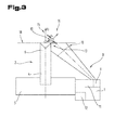
- Fig. 1-3 the situation for a bending press for bending and / or embossing bending is shown, wherein the bending tool assembly 2 has at least one upper tool 3 and one lower tool 4.
- the bending tool assembly 2 is arranged on the machine position 5, which, again for reasons of simplification, in the Fig. 1-3 is shown very schematically. In particular, all the machine components of the bending machine required for carrying out the bending deformation are not shown for reasons of simplification.
- Fig. 1 shows a possible embodiment of a bending machine with a bending angle measuring device 1, wherein the bending machine has a bending tool assembly 2.
- the reference feature 6 is formed in this embodiment by a stop device 7, in particular a backgauge.
- the stop device 7 has been moved by the machine control of the bending machine into the detection area 8 of the bending angle measuring device 1.
- a light pattern is emitted to the sheet metal surface to be detected.
- the illuminated by the light pattern sheet surface is detected by an image capture device 11, further comprising an evaluation module 12 from the detected image determines a current actual bending angle.
- a light pattern 10 is now also directed by the illumination device 9 onto the reference feature 6 moved into the detection area 8 of the bending angle measuring device 1, and the projected image of the light pattern 10 is detected by the image acquisition device 11.
- a reference point 13 of the reference feature 6 is then detected in the acquired image, wherein this reference point 13 is characterized in that it is reliably detectable as a unique feature on the reference feature 6.
- this may for example be an edge of a stop finger 14 of the stop device 7.
- the reference point does not just mean a point in the mathematical sense, but rather that an excellent feature is characterized, and thus, as in the present case, it can also be an edge or a line.
- the bending machine When commissioning the bending machine, the bending machine is assigned a first coordinate system 15. Thus, the reference feature 6 and in particular the reference point 13, clearly defined in the first coordinate system 15. Likewise, the bending angle measuring device 1 is assigned a second coordinate system 16, whereby each detected point in the detection area 8 is uniquely determined in the second coordinate system 16. After the objective method, a transformation matrix 17 is now determined between the first 15 and the second 16 coordinate system.
- Fig. 1 shows a further possible embodiment, in which not only the stop device 7 serves as a reference feature 6, but where also the lower tool 4 of the bending tool assembly 2 is used as a reference feature with a reference point.
- the lower tool 4 of the bending tool assembly 2 is used as a reference feature with a reference point.
- an edge of the bending recess of the lower tool 4 can additionally be used as a reference point and thus increases the calibration accuracy.
- the use of the lower tool 4 as a reference feature further has the advantage that this lower tool 4 is usually also during the execution of the bending deformation in the detection area 8 of the bending angle measuring device 1 and thus a check of the calibration is possible even during the execution of the bending deformation.
- Fig. 2 shows a further possible embodiment in which the upper 3 and the lower tool 4 of the bending tool assembly 2 serve as a reference feature. Since the tools of the bending tool assembly 2 are mostly mechanically very accurately worked and are known exactly in terms of their geometric dimensions, is thus also or the reference points 13 in the first coordinate system 15 of the bending machine accurately known. For example, the upper tool 3 can now be positioned by the bending machine at a defined distance from the lower tool 4, whereupon subsequently in the calibration of the bending angle measuring device 1 of the two reference points 13 in the second coordinate system 16 of the bending angle measuring device 1 are determined. Thus, in turn, a transformation matrix 17 can be determined and this, while performing the bending deformation, be applied to the bending angle determined by the bending angle measuring device 1.
- a person skilled in the Fig. 1-3 illustrated variants could also move to a folding machine.
- the sheet is held in a swing bending machine between the upper and lower hold-down tool and bent by an upper or lower bending beam tool in the desired direction. Since during the execution of the bending deformation of the bending angle measuring device, the sheet metal surface bent by the upper or lower bending beam tool is detected and the current bending angle is determined therefrom, a reference point in the first coordinate system of the pivoting bending machine can also be used with the objective calibration method determined transformation matrix in the second coordinate system of the bending angle measuring device or in relation to this second coordinate system, are determined.
- the illumination device of the bending angle measuring device directs a light pattern onto the sheet metal surface of the sheet metal part to be formed and during the calibration process a light pattern onto the reference feature.
- This can be the same light pattern in both cases, but it is also possible that another, different light pattern is used for the calibration, for example, a light line, which has a strong local contrast and thus preferably for the detection of lines and edges suitable.
Landscapes
- Engineering & Computer Science (AREA)
- Physics & Mathematics (AREA)
- General Physics & Mathematics (AREA)
- Mechanical Engineering (AREA)
- Computer Vision & Pattern Recognition (AREA)
- Bending Of Plates, Rods, And Pipes (AREA)
Applications Claiming Priority (1)
| Application Number | Priority Date | Filing Date | Title |
|---|---|---|---|
| ATA50643/2014A AT516146B1 (de) | 2014-09-15 | 2014-09-15 | Kalibrierverfahren für eine Biegemaschine |
Publications (3)
| Publication Number | Publication Date |
|---|---|
| EP2995391A2 true EP2995391A2 (fr) | 2016-03-16 |
| EP2995391A3 EP2995391A3 (fr) | 2016-03-23 |
| EP2995391B1 EP2995391B1 (fr) | 2018-08-08 |
Family
ID=54140347
Family Applications (1)
| Application Number | Title | Priority Date | Filing Date |
|---|---|---|---|
| EP15184997.3A Active EP2995391B1 (fr) | 2014-09-15 | 2015-09-14 | Procede d'etalonnage pour une cintreuse et une telle cintreuse |
Country Status (2)
| Country | Link |
|---|---|
| EP (1) | EP2995391B1 (fr) |
| AT (1) | AT516146B1 (fr) |
Cited By (1)
| Publication number | Priority date | Publication date | Assignee | Title |
|---|---|---|---|---|
| US12214403B2 (en) * | 2021-03-25 | 2025-02-04 | Bystronic Laser Ag | Method and device for determining a bending angle on a bending machine |
Families Citing this family (3)
| Publication number | Priority date | Publication date | Assignee | Title |
|---|---|---|---|---|
| AT518637B1 (de) * | 2016-08-24 | 2017-12-15 | Keba Ag | Vorrichtung zum Ausrichten eines Winkelmessgeräts |
| AT520085B1 (de) * | 2017-07-17 | 2019-01-15 | Trumpf Maschinen Austria Gmbh & Co Kg | Biegepresse und Verfahren zum Betrieb einer Biegepresse |
| JP7234737B2 (ja) * | 2019-03-28 | 2023-03-08 | 株式会社デンソー | 検出ユニット |
Citations (1)
| Publication number | Priority date | Publication date | Assignee | Title |
|---|---|---|---|---|
| EP1102032B1 (fr) | 1999-11-19 | 2005-10-05 | LVD Company NV | Procédé et dispositif pour la mesure de l'angle de pliage d'une feuille dans une plieuse |
Family Cites Families (11)
| Publication number | Priority date | Publication date | Assignee | Title |
|---|---|---|---|---|
| WO1991013318A1 (fr) * | 1990-02-23 | 1991-09-05 | Amada Company, Limited | Procede et appareil de mesure d'angles de façonnage |
| US5531087A (en) * | 1990-10-05 | 1996-07-02 | Kabushiki Kaisha Komatsu Seisakusho | Metal sheet bending machine |
| JP2641829B2 (ja) * | 1992-11-10 | 1997-08-20 | 株式会社小松製作所 | 曲げ加工機における曲げ角度検出装置 |
| WO1994027756A1 (fr) * | 1993-05-24 | 1994-12-08 | Kabushiki Kaisha Komatsu Seisakusho | Dispositif permettant de detecter un angle de pliage et systeme d'extraction de lignes droites utilisees a cet effet, et appareil pour le reglage de la position de detection d'un angle de pliage |
| NL1010801C1 (nl) * | 1998-10-19 | 2000-04-20 | Cornelis Hendricus Liet | Inrichting voor het buigen van werkstukken, alsmede meetinrichting voor een dergelijke inrichting. |
| WO2002003026A1 (fr) * | 2000-07-04 | 2002-01-10 | Fastcom Technology S.A. | Systeme et procede de mesure d'angle |
| CH695668A5 (de) * | 2002-03-14 | 2006-07-31 | Goeran Rostroem | Mess- und Steuervorrichtung in einer Abkantfpresse. |
| ITPR20040010A1 (it) * | 2004-02-18 | 2004-05-18 | Set 2002 S R L | Procedimento e dispositivo pneumatico per rilevare l'angolo di piega di un foglio di lamiera in una pressa piegatrice. |
| AT509024B1 (de) * | 2009-11-02 | 2012-10-15 | Trumpf Maschinen Austria Gmbh | Verfahren zur bestimmung der ausrichtung eines oberen teils eines stückgutstapels |
| DE202010006391U1 (de) * | 2010-05-04 | 2010-11-04 | Bystronic Laser Ag | Winkelmessvorrichtung für Abkantpressen |
| PL2719475T3 (pl) * | 2012-10-12 | 2019-05-31 | Nivora Ip B V | Układ pomiarowy oraz sposób pomiaru kąta |
-
2014
- 2014-09-15 AT ATA50643/2014A patent/AT516146B1/de not_active IP Right Cessation
-
2015
- 2015-09-14 EP EP15184997.3A patent/EP2995391B1/fr active Active
Patent Citations (1)
| Publication number | Priority date | Publication date | Assignee | Title |
|---|---|---|---|---|
| EP1102032B1 (fr) | 1999-11-19 | 2005-10-05 | LVD Company NV | Procédé et dispositif pour la mesure de l'angle de pliage d'une feuille dans une plieuse |
Cited By (1)
| Publication number | Priority date | Publication date | Assignee | Title |
|---|---|---|---|---|
| US12214403B2 (en) * | 2021-03-25 | 2025-02-04 | Bystronic Laser Ag | Method and device for determining a bending angle on a bending machine |
Also Published As
| Publication number | Publication date |
|---|---|
| AT516146B1 (de) | 2016-03-15 |
| AT516146A4 (de) | 2016-03-15 |
| EP2995391A3 (fr) | 2016-03-23 |
| EP2995391B1 (fr) | 2018-08-08 |
Similar Documents
| Publication | Publication Date | Title |
|---|---|---|
| AT508857B1 (de) | Verfahren zur bestimmung der dicke eines werkstückes mit einer biegemaschine | |
| AT518993B1 (de) | Verfahren zum Betrieb einer Biegemaschine | |
| WO2016094918A1 (fr) | Outil de cintrage ayant un dispositif de mesure de décalage longitudinal | |
| DE3216053A1 (de) | Optoelektronisches messverfahren und vorrichtung zur durchfuehrung des verfahrens | |
| AT515944B1 (de) | Biegewinkel-Messverfahren | |
| EP2995391B1 (fr) | Procede d'etalonnage pour une cintreuse et une telle cintreuse | |
| EP2709779B1 (fr) | Dispositif de mesure d'angles destiné à une presse plieuse | |
| EP3566793B1 (fr) | Détection de matière en excès à couper pour cellules de pliage | |
| EP3655175B1 (fr) | Procédé de fonctionnement d'une installation d'usinage équipée d'un piston mobile | |
| EP3158288B1 (fr) | Dispositif de mesure d'angles de pliage destiné à une presse de pliage | |
| EP3445510B1 (fr) | Barre de pliage pour plieuse pivotante | |
| EP3215284B1 (fr) | Outil de cintrage avec dispositif de mesure de la géométrie de cintrage | |
| AT522419A1 (de) | Messvorrichtung zur Bestimmung des Biegewinkels | |
| EP3253507B1 (fr) | Dispositif de pliage avec instrument de mesure | |
| EP3794308A1 (fr) | Calcul d'une orientation d'au moins un objet et procédé destiné à orienter relativement des galets | |
| EP2983842B1 (fr) | Presse plieuse avec un dispositif de mesure d'angle de pliage | |
| EP2614900B1 (fr) | Dispositif de fabrication avec outils de pliage et outil de positionnement | |
| AT523360A1 (de) | Biegemaschine und Kontrolleinrichtung | |
| EP2147729A1 (fr) | Dispositif de déformation | |
| AT516044B1 (de) | Biegewinkel-Messvorrichtung |
Legal Events
| Date | Code | Title | Description |
|---|---|---|---|
| PUAL | Search report despatched |
Free format text: ORIGINAL CODE: 0009013 |
|
| PUAI | Public reference made under article 153(3) epc to a published international application that has entered the european phase |
Free format text: ORIGINAL CODE: 0009012 |
|
| AK | Designated contracting states |
Kind code of ref document: A2 Designated state(s): AL AT BE BG CH CY CZ DE DK EE ES FI FR GB GR HR HU IE IS IT LI LT LU LV MC MK MT NL NO PL PT RO RS SE SI SK SM TR |
|
| AX | Request for extension of the european patent |
Extension state: BA ME |
|
| AK | Designated contracting states |
Kind code of ref document: A3 Designated state(s): AL AT BE BG CH CY CZ DE DK EE ES FI FR GB GR HR HU IE IS IT LI LT LU LV MC MK MT NL NO PL PT RO RS SE SI SK SM TR |
|
| AX | Request for extension of the european patent |
Extension state: BA ME |
|
| RIC1 | Information provided on ipc code assigned before grant |
Ipc: G01B 11/26 20060101ALI20160212BHEP Ipc: B21D 5/00 20060101AFI20160212BHEP Ipc: B21D 5/02 20060101ALI20160212BHEP |
|
| 17P | Request for examination filed |
Effective date: 20160923 |
|
| RBV | Designated contracting states (corrected) |
Designated state(s): AL AT BE BG CH CY CZ DE DK EE ES FI FR GB GR HR HU IE IS IT LI LT LU LV MC MK MT NL NO PL PT RO RS SE SI SK SM TR |
|
| RIN1 | Information on inventor provided before grant (corrected) |
Inventor name: LUSTIG, STEFAN Inventor name: LEEB, SEBASTIAN |
|
| GRAP | Despatch of communication of intention to grant a patent |
Free format text: ORIGINAL CODE: EPIDOSNIGR1 |
|
| STAA | Information on the status of an ep patent application or granted ep patent |
Free format text: STATUS: GRANT OF PATENT IS INTENDED |
|
| RIC1 | Information provided on ipc code assigned before grant |
Ipc: G01B 11/26 20060101ALI20180124BHEP Ipc: B21D 5/02 20060101ALI20180124BHEP Ipc: B21D 5/00 20060101AFI20180124BHEP |
|
| INTG | Intention to grant announced |
Effective date: 20180222 |
|
| GRAS | Grant fee paid |
Free format text: ORIGINAL CODE: EPIDOSNIGR3 |
|
| GRAJ | Information related to disapproval of communication of intention to grant by the applicant or resumption of examination proceedings by the epo deleted |
Free format text: ORIGINAL CODE: EPIDOSDIGR1 |
|
| GRAL | Information related to payment of fee for publishing/printing deleted |
Free format text: ORIGINAL CODE: EPIDOSDIGR3 |
|
| STAA | Information on the status of an ep patent application or granted ep patent |
Free format text: STATUS: REQUEST FOR EXAMINATION WAS MADE |
|
| INTC | Intention to grant announced (deleted) | ||
| RAP1 | Party data changed (applicant data changed or rights of an application transferred) |
Owner name: TRUMPF MASCHINEN AUSTRIA GMBH & CO. KG. |
|
| GRAR | Information related to intention to grant a patent recorded |
Free format text: ORIGINAL CODE: EPIDOSNIGR71 |
|
| STAA | Information on the status of an ep patent application or granted ep patent |
Free format text: STATUS: GRANT OF PATENT IS INTENDED |
|
| GRAA | (expected) grant |
Free format text: ORIGINAL CODE: 0009210 |
|
| STAA | Information on the status of an ep patent application or granted ep patent |
Free format text: STATUS: THE PATENT HAS BEEN GRANTED |
|
| INTG | Intention to grant announced |
Effective date: 20180628 |
|
| AK | Designated contracting states |
Kind code of ref document: B1 Designated state(s): AL AT BE BG CH CY CZ DE DK EE ES FI FR GB GR HR HU IE IS IT LI LT LU LV MC MK MT NL NO PL PT RO RS SE SI SK SM TR |
|
| REG | Reference to a national code |
Ref country code: GB Ref legal event code: FG4D Free format text: NOT ENGLISH |
|
| REG | Reference to a national code |
Ref country code: CH Ref legal event code: EP Ref country code: AT Ref legal event code: REF Ref document number: 1026407 Country of ref document: AT Kind code of ref document: T Effective date: 20180815 |
|
| REG | Reference to a national code |
Ref country code: IE Ref legal event code: FG4D Free format text: LANGUAGE OF EP DOCUMENT: GERMAN |
|
| REG | Reference to a national code |
Ref country code: DE Ref legal event code: R096 Ref document number: 502015005368 Country of ref document: DE |
|
| REG | Reference to a national code |
Ref country code: FR Ref legal event code: PLFP Year of fee payment: 4 |
|
| REG | Reference to a national code |
Ref country code: CH Ref legal event code: NV Representative=s name: ABP PATENT NETWORK AG, CH |
|
| REG | Reference to a national code |
Ref country code: NL Ref legal event code: MP Effective date: 20180808 |
|
| REG | Reference to a national code |
Ref country code: LT Ref legal event code: MG4D |
|
| PG25 | Lapsed in a contracting state [announced via postgrant information from national office to epo] |
Ref country code: FI Free format text: LAPSE BECAUSE OF FAILURE TO SUBMIT A TRANSLATION OF THE DESCRIPTION OR TO PAY THE FEE WITHIN THE PRESCRIBED TIME-LIMIT Effective date: 20180808 Ref country code: PL Free format text: LAPSE BECAUSE OF FAILURE TO SUBMIT A TRANSLATION OF THE DESCRIPTION OR TO PAY THE FEE WITHIN THE PRESCRIBED TIME-LIMIT Effective date: 20180808 Ref country code: BG Free format text: LAPSE BECAUSE OF FAILURE TO SUBMIT A TRANSLATION OF THE DESCRIPTION OR TO PAY THE FEE WITHIN THE PRESCRIBED TIME-LIMIT Effective date: 20181108 Ref country code: GR Free format text: LAPSE BECAUSE OF FAILURE TO SUBMIT A TRANSLATION OF THE DESCRIPTION OR TO PAY THE FEE WITHIN THE PRESCRIBED TIME-LIMIT Effective date: 20181109 Ref country code: SE Free format text: LAPSE BECAUSE OF FAILURE TO SUBMIT A TRANSLATION OF THE DESCRIPTION OR TO PAY THE FEE WITHIN THE PRESCRIBED TIME-LIMIT Effective date: 20180808 Ref country code: NO Free format text: LAPSE BECAUSE OF FAILURE TO SUBMIT A TRANSLATION OF THE DESCRIPTION OR TO PAY THE FEE WITHIN THE PRESCRIBED TIME-LIMIT Effective date: 20181108 Ref country code: RS Free format text: LAPSE BECAUSE OF FAILURE TO SUBMIT A TRANSLATION OF THE DESCRIPTION OR TO PAY THE FEE WITHIN THE PRESCRIBED TIME-LIMIT Effective date: 20180808 Ref country code: NL Free format text: LAPSE BECAUSE OF FAILURE TO SUBMIT A TRANSLATION OF THE DESCRIPTION OR TO PAY THE FEE WITHIN THE PRESCRIBED TIME-LIMIT Effective date: 20180808 Ref country code: LT Free format text: LAPSE BECAUSE OF FAILURE TO SUBMIT A TRANSLATION OF THE DESCRIPTION OR TO PAY THE FEE WITHIN THE PRESCRIBED TIME-LIMIT Effective date: 20180808 Ref country code: IS Free format text: LAPSE BECAUSE OF FAILURE TO SUBMIT A TRANSLATION OF THE DESCRIPTION OR TO PAY THE FEE WITHIN THE PRESCRIBED TIME-LIMIT Effective date: 20181208 |
|
| PG25 | Lapsed in a contracting state [announced via postgrant information from national office to epo] |
Ref country code: HR Free format text: LAPSE BECAUSE OF FAILURE TO SUBMIT A TRANSLATION OF THE DESCRIPTION OR TO PAY THE FEE WITHIN THE PRESCRIBED TIME-LIMIT Effective date: 20180808 Ref country code: AL Free format text: LAPSE BECAUSE OF FAILURE TO SUBMIT A TRANSLATION OF THE DESCRIPTION OR TO PAY THE FEE WITHIN THE PRESCRIBED TIME-LIMIT Effective date: 20180808 Ref country code: LV Free format text: LAPSE BECAUSE OF FAILURE TO SUBMIT A TRANSLATION OF THE DESCRIPTION OR TO PAY THE FEE WITHIN THE PRESCRIBED TIME-LIMIT Effective date: 20180808 |
|
| PG25 | Lapsed in a contracting state [announced via postgrant information from national office to epo] |
Ref country code: ES Free format text: LAPSE BECAUSE OF FAILURE TO SUBMIT A TRANSLATION OF THE DESCRIPTION OR TO PAY THE FEE WITHIN THE PRESCRIBED TIME-LIMIT Effective date: 20180808 Ref country code: EE Free format text: LAPSE BECAUSE OF FAILURE TO SUBMIT A TRANSLATION OF THE DESCRIPTION OR TO PAY THE FEE WITHIN THE PRESCRIBED TIME-LIMIT Effective date: 20180808 Ref country code: CZ Free format text: LAPSE BECAUSE OF FAILURE TO SUBMIT A TRANSLATION OF THE DESCRIPTION OR TO PAY THE FEE WITHIN THE PRESCRIBED TIME-LIMIT Effective date: 20180808 Ref country code: RO Free format text: LAPSE BECAUSE OF FAILURE TO SUBMIT A TRANSLATION OF THE DESCRIPTION OR TO PAY THE FEE WITHIN THE PRESCRIBED TIME-LIMIT Effective date: 20180808 |
|
| REG | Reference to a national code |
Ref country code: DE Ref legal event code: R097 Ref document number: 502015005368 Country of ref document: DE |
|
| PG25 | Lapsed in a contracting state [announced via postgrant information from national office to epo] |
Ref country code: DK Free format text: LAPSE BECAUSE OF FAILURE TO SUBMIT A TRANSLATION OF THE DESCRIPTION OR TO PAY THE FEE WITHIN THE PRESCRIBED TIME-LIMIT Effective date: 20180808 Ref country code: SK Free format text: LAPSE BECAUSE OF FAILURE TO SUBMIT A TRANSLATION OF THE DESCRIPTION OR TO PAY THE FEE WITHIN THE PRESCRIBED TIME-LIMIT Effective date: 20180808 Ref country code: SM Free format text: LAPSE BECAUSE OF FAILURE TO SUBMIT A TRANSLATION OF THE DESCRIPTION OR TO PAY THE FEE WITHIN THE PRESCRIBED TIME-LIMIT Effective date: 20180808 |
|
| PLBE | No opposition filed within time limit |
Free format text: ORIGINAL CODE: 0009261 |
|
| STAA | Information on the status of an ep patent application or granted ep patent |
Free format text: STATUS: NO OPPOSITION FILED WITHIN TIME LIMIT |
|
| REG | Reference to a national code |
Ref country code: IE Ref legal event code: MM4A |
|
| PG25 | Lapsed in a contracting state [announced via postgrant information from national office to epo] |
Ref country code: MC Free format text: LAPSE BECAUSE OF FAILURE TO SUBMIT A TRANSLATION OF THE DESCRIPTION OR TO PAY THE FEE WITHIN THE PRESCRIBED TIME-LIMIT Effective date: 20180808 Ref country code: LU Free format text: LAPSE BECAUSE OF NON-PAYMENT OF DUE FEES Effective date: 20180914 |
|
| 26N | No opposition filed |
Effective date: 20190509 |
|
| PG25 | Lapsed in a contracting state [announced via postgrant information from national office to epo] |
Ref country code: IE Free format text: LAPSE BECAUSE OF NON-PAYMENT OF DUE FEES Effective date: 20180914 |
|
| PG25 | Lapsed in a contracting state [announced via postgrant information from national office to epo] |
Ref country code: SI Free format text: LAPSE BECAUSE OF FAILURE TO SUBMIT A TRANSLATION OF THE DESCRIPTION OR TO PAY THE FEE WITHIN THE PRESCRIBED TIME-LIMIT Effective date: 20180808 |
|
| PGFP | Annual fee paid to national office [announced via postgrant information from national office to epo] |
Ref country code: BE Payment date: 20190613 Year of fee payment: 5 |
|
| PGFP | Annual fee paid to national office [announced via postgrant information from national office to epo] |
Ref country code: FR Payment date: 20190708 Year of fee payment: 5 |
|
| PGFP | Annual fee paid to national office [announced via postgrant information from national office to epo] |
Ref country code: GB Payment date: 20190724 Year of fee payment: 5 |
|
| PG25 | Lapsed in a contracting state [announced via postgrant information from national office to epo] |
Ref country code: MT Free format text: LAPSE BECAUSE OF FAILURE TO SUBMIT A TRANSLATION OF THE DESCRIPTION OR TO PAY THE FEE WITHIN THE PRESCRIBED TIME-LIMIT Effective date: 20180808 |
|
| PGFP | Annual fee paid to national office [announced via postgrant information from national office to epo] |
Ref country code: CH Payment date: 20190729 Year of fee payment: 5 |
|
| PG25 | Lapsed in a contracting state [announced via postgrant information from national office to epo] |
Ref country code: TR Free format text: LAPSE BECAUSE OF FAILURE TO SUBMIT A TRANSLATION OF THE DESCRIPTION OR TO PAY THE FEE WITHIN THE PRESCRIBED TIME-LIMIT Effective date: 20180808 |
|
| PG25 | Lapsed in a contracting state [announced via postgrant information from national office to epo] |
Ref country code: PT Free format text: LAPSE BECAUSE OF FAILURE TO SUBMIT A TRANSLATION OF THE DESCRIPTION OR TO PAY THE FEE WITHIN THE PRESCRIBED TIME-LIMIT Effective date: 20180808 |
|
| PG25 | Lapsed in a contracting state [announced via postgrant information from national office to epo] |
Ref country code: HU Free format text: LAPSE BECAUSE OF FAILURE TO SUBMIT A TRANSLATION OF THE DESCRIPTION OR TO PAY THE FEE WITHIN THE PRESCRIBED TIME-LIMIT; INVALID AB INITIO Effective date: 20150914 Ref country code: MK Free format text: LAPSE BECAUSE OF NON-PAYMENT OF DUE FEES Effective date: 20180808 Ref country code: CY Free format text: LAPSE BECAUSE OF FAILURE TO SUBMIT A TRANSLATION OF THE DESCRIPTION OR TO PAY THE FEE WITHIN THE PRESCRIBED TIME-LIMIT Effective date: 20180808 |
|
| REG | Reference to a national code |
Ref country code: CH Ref legal event code: PL |
|
| GBPC | Gb: european patent ceased through non-payment of renewal fee |
Effective date: 20200914 |
|
| REG | Reference to a national code |
Ref country code: BE Ref legal event code: MM Effective date: 20200930 |
|
| PG25 | Lapsed in a contracting state [announced via postgrant information from national office to epo] |
Ref country code: FR Free format text: LAPSE BECAUSE OF NON-PAYMENT OF DUE FEES Effective date: 20200930 |
|
| PG25 | Lapsed in a contracting state [announced via postgrant information from national office to epo] |
Ref country code: LI Free format text: LAPSE BECAUSE OF NON-PAYMENT OF DUE FEES Effective date: 20200930 Ref country code: GB Free format text: LAPSE BECAUSE OF NON-PAYMENT OF DUE FEES Effective date: 20200914 Ref country code: CH Free format text: LAPSE BECAUSE OF NON-PAYMENT OF DUE FEES Effective date: 20200930 Ref country code: BE Free format text: LAPSE BECAUSE OF NON-PAYMENT OF DUE FEES Effective date: 20200930 |
|
| REG | Reference to a national code |
Ref country code: AT Ref legal event code: MM01 Ref document number: 1026407 Country of ref document: AT Kind code of ref document: T Effective date: 20200914 |
|
| PG25 | Lapsed in a contracting state [announced via postgrant information from national office to epo] |
Ref country code: AT Free format text: LAPSE BECAUSE OF NON-PAYMENT OF DUE FEES Effective date: 20200914 |
|
| PGFP | Annual fee paid to national office [announced via postgrant information from national office to epo] |
Ref country code: IT Payment date: 20230908 Year of fee payment: 9 |
|
| PG25 | Lapsed in a contracting state [announced via postgrant information from national office to epo] |
Ref country code: IT Free format text: LAPSE BECAUSE OF NON-PAYMENT OF DUE FEES Effective date: 20240914 |
|
| PGFP | Annual fee paid to national office [announced via postgrant information from national office to epo] |
Ref country code: DE Payment date: 20250917 Year of fee payment: 11 |